1
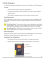
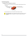
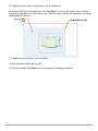
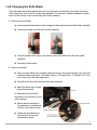
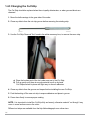
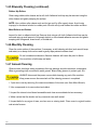
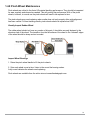
hs
AXXIS
Operations Manual
Manual Version 2.3 November 2014
Congratulations on your new purchase!
Copyright Allen Datagraph Systems Inc. - All rights reserved.
56 Kendall Pond Road
Derry, NH 03038
603-216-6344
www.allendatagraph.com
01
All products made in The United States.
All specifications are subject to change.
02
Thank You for Selecting an Allen Datagraph Product
At Allen Datagraph Systems, Inc. (ADSI), we are committed to serving you, our customer. Our goal is
to provide you with competitive, quality products and services to meet your needs. Customer input is of
great value to Allen Datagraph Systems, Inc.; therefore, we encourage any comments or suggestions.
The instructions contained in this manual are intended to ensure the safe installation, operation,
and maintenance of your machine. Please read this manual carefully before performing any activity
on the equipment. Please note information contained in this manual does not modify or alter, in any
way, the standard terms, and conditions of your Allen Datagraph Systems, Inc. purchase contract.
This manual should be readily accessible to operating and maintenance personnel at all times.
Proper use of this manual, in addition to other Original Equipment Manufacturer’s manuals and your
in-house manuals, will assure safe, reliable and cost-effective performance of ADSI machinery.
If you are in need of service, please contact our Technical Support staff as instructed on the following
pages. In order to expedite your request please include the serial number of your machine. Each Allen
Datagraph Systems, Inc. machine has a label identifying its serial number.
General Information
Allen Datagraph Systems, Inc. (Hereafter known as ADSI) Operating Manuals and Addenda
provide a general understanding of the operation of the contracted system, its major components,
and the functional elements of those components.
The Manuals and Addenda contain Safety, Description, Installation, Operation, and Maintenance
information. We strongly recommend thoroughly reading and understanding the information in this
manual before operating this equipment. If additional information is required, or clarification needed,
feel free to contact ADSI.
The Manuals and Addenda may not be copied or reproduced, in whole or part, without written
consent of Allen Datagraph Systems, Inc
Receiving and Inspecting the Equipment
Inspect the ADSI equipment immediately upon arrival at the installation site as follows:
· Note any visual in-transit damage to the packing crate or the equipment on the carrier’s delivery slip.
· Report any concealed in-transit damage to the delivery carrier and to ADSI as soon as it is discovered. When possible, take pictures for claim purposes.
· Cross-reference amounts received to amounts shipped as indicated on the packing lists forwarded with the machinery. Report shortages and/or defective material immediately to ADSI customer service office.
· ADSI may require defective components to be returned in order to issue credit under warranty. Do not return any items without first contacting ADSI and obtaining a Return 03
Authorization.
Disclaimer of Warranties and Limitation of Liabilities
ADSI Digital Finishing Systems are warranted free of defects in both materials and workmanship.
Should any part of this equipment be defective, it will be repaired or replaced, at the option of the
manufacturer, at no charge for parts or factory labor for a period of one (1) year from the date of installation. All warranty services are performed at the ADSI factory. Replacement parts not installed
at the factory will be billed to the customer at regular prices and credit will be issued when the defective parts are returned. The customer is responsible for freight on warranty parts and repairs.
This warranty is void if:
The equipment has been damaged by negligence, accident or mishandling, or has not been operated
in accordance with the procedures described in the operating instructions;
or:
The equipment has been altered or repaired by other than an approved service station or factory
service center, or adaptations or accessories have been attached to the equipment that shall have
adversely affected the performance, safety, or reliability of the equipment.
NO OTHER WARRANTY, EXPRESSED OR IMPLIED, APPLIES to the equipment. ADSI does not
assume any responsibility for consequential damages occasioned by the equipment, or inconvenience or interruption in operation.
In case of unsatisfactory operation, ADSI or its Dealer should be notified immediately.
Technical Support
Technical support is available during business hours based on Eastern Time Monday through
Friday 7:30 am to 4:30 pm.
For Technical support please access our free e-mail support or visit our web site at http://www.
allendatagraph.com, and then clicking on tech support and the email link.
Service Policy – All service is subject to ADSI service policy. You can read the policy here: Web
Site Copy - http://allendatagraph.com/wp-content/uploads/2014/01/ADSI-ServicePolicy.pdf
There are many online documents available to help you to operate the Axxis HS at our technical
support page at http://www.allendatagraph.com. Hover over Tech Support, then click download
drivers and documents, then click download current library, then Label Production, then Axxis HS.
04
Specifications
System Data:
Contour Cutting
Max Frame Length
Max Input Roll Diameter
Max Output Roll Diameter
Recommended Roll Length
Web Width
Cutting Technology
User Interface
Test Cut Function
Full HPGL vector cutting
compatible with SMARTMark
opto-electrical line sensor
14 inches | 35.5 cm
8 inches | 20 cm
8 inches | 20 cm
500 feet | 153 meters
4 - 8.5 inches | 10 - 21.5 cm
Pivoting carbide tip - 30, 45 &
60 degree
Touch panel display
Yes
Network Connections:
Ethernet
USB
· 100BASE-TX
· 10BASE-T
High Speed 2.0
Power Requirements:
Axxis HS Print Base & Printer:
100-132 VAC / 47-63 Hz 5A or
180-240 VAC / 47-63 Hz 2.5A
Dimensions and Weight:
Height
Width
Depth
Weight
22 inches | 56 cm
31 inches | 79 cm
21 inches | 53 cm
200 Lbs (91 Kg)
05
Items Shipped Unassembled from Machine
An accessory kit is shipped with the equipment in the crate. These items are required for operating
the Axxis HS finisher. The tools included in this kit are specifically sized for the machine and should
be stored nearby for easy access. The kit contains the following items:
Accessory Kit:
06
Component ID
Description
Qty
30040018
40239063
DT-00-11-141
DT-423
PL-00-03-533
DT-413
F-045
F-054
H03-032
H05-353
H05-361
H05-360
H21-021
H21-022
H21-023
H21-024
H21-010
LS-179
H20-007
H20-008
H20-017
PL-00-02-865
PL-00-02-867
CN-016-10
DT-149
Weed Bar O-Rings
AC Power Cord, European Style
Web Centering Gauge
1.5 MM Hex Driver
CD, Software/Documentation
Cut Strip Removal Tool
5A Normal Blow Fuse
2.5 A Slow Blow Fuse
Pinch Wheel Spring (Meduim Tension)
Ethernet Crossover Adapter
Black CAT 5E Ethernet Patch Cable, 14ft
USB Cable, 10ft Grey (A Male to B Male)
3.0 MM Hex Key Wrench (L Short Arm)
2.0 MM Hex Key Wrench (L Short Arm)
1.5 MM Hex Key Wrench (L Short Arm)
4.0 MM Hex Key Wrench (L Short Arm)
3/32 IN Hex Wrench (L Shaped)
7/64 IN Hex Wrench (Long)
45 Degree Knife Blade (Red Cap)
60 Degree Knife Blade (Green Cap)
30 Degree Knife Blade (Blue Cap)
Control Dept Knife Holder
Advanced Control Dept Knife Holder (Gold)
Slitter Blade 10pk
Core Partition Flange
12
1
1
1
1
1
2
2
4
1
1
1
1
1
1
1
1
1
1
1
1
1
1
1
5
Table of Contents
1.0.0 Introduction . . . . . . . . . . . . . . . . . . . . . . . . . . . . . . . . . . . . . . . . . . . . . . . . . . . . . . . . . . . . . . 08
1.0.1 Safety . . . . . . . . . . . . . . . . . . . . . . . . . . . . . . . . . . . . . . . . . . . . . . . . . . . . . . . . . . . . . . . . . . . 08
1.0.2 Site Preparation . . . . . . . . . . . . . . . . . . . . . . . . . . . . . . . . . . . . . . . . . . . . . . . . . . . . . . . . . . 09
1.1.0 Installation of Axxis HS Digital Label Finsiher . . . . . . . . . . . . . . . . . . . . . . . . . . . . . . . . . . . 11
1.1.1 Setup Finisher . . . . . . . . . . . . . . . . . . . . . . . . . . . . . . . . . . . . . . . . . . . . . . . . . . . . . . . . . . . . . 11
1.1.2 Connection to PC . . . . . . . . . . . . . . . . . . . . . . . . . . . . . . . . . . . . . . . . . . . . . . . . . . . . . . . . . . 11
1.1.3 Allen Datagraph Installation Disc . . . . . . . . . . . . . . . . . . . . . . . . . . . . . . . . . . . . . . . . . . . . . . 11
1.2.0 Setting up your label job . . . . . . . . . . . . . . . . . . . . . . . . . . . . . . . . . . . . . . . . . . . . . . . . . . . . 12
1.2.1 Explanation of SmartMark . . . . . . . . . . . . . . . . . . . . . . . . . . . . . . . . . . . . . . . . . . . . . . . . . 12
1.2.2 Registration Mark Placement and File Creation . . . . . . . . . . . . . . . . . . . . . . . . . . . . . . . . . 12
1.2.3 Multiple Registration Marks . . . . . . . . . . . . . . . . . . . . . . . . . . . . . . . . . . . . . . . . . . . . . . . . . . 15
1.2.4 Creating the “Cut” File for the Finisher. . . . . . . . . . . . . . . . . . . . . . . . . . . . . . . . . . . . . . . . . 16
1.2.4.1 Creating Plot File with Adobe Illustraitor . . . . . . . . . . . . . . . . . . . . . . . . . . . . . . . . . . . . . . 16
1.2.4.2 Creating Plot File with CorelDraw . . . . . . . . . . . . . . . . . . . . . . . . . . . . . . . . . . . . . . . . . . . . 16
1.2.5 Allen DircetCut Properties . . . . . . . . . . . . . . . . . . . . . . . . . . . . . . . . . . . . . . . . . . . . . . . . . . . 17
1.2.5.1 Space Between Jobs . . . . . . . . . . . . . . . . . . . . . . . . . . . . . . . . . . . . . . . . . . . . . . . . . . . . 18
1.2.6 Webbing the Axxis HS Digital Label Finisher . . . . . . . . . . . . . . . . . . . . . . . . . . . . . . . . . . . . 19
1.2.6.1 Webbing the Laminate on the Axxis HS Digital Label Finisher . . . . . . . . . . . . . . . . . . . . 19
1.2.6.2 Webbing test Axxis HS Digital Label Finisher . . . . . . . . . . . . . . . . . . . . . . . . . . . . . . . . . . . 20
1.2.6.3 Test Cut on Axxis HS Digital Label Finisher . . . . . . . . . . . . . . . . . . . . . . . . . . . . . . . . . . . 21
1.2.6.4 Sending Cut Files to Axxis HS Digital Label Finisher . . . . . . . . . . . . . . . . . . . . . . . . . . . . 22
1.3.0 Using Accessories . . . . . . . . . . . . . . . . . . . . . . . . . . . . . . . . . . . . . . . . . . . . . . . . . . . . . . . . . 23
1.3.1 Weed Bar . . . . . . . . . . . . . . . . . . . . . . . . . . . . . . . . . . . . . . . . . . . . . . . . . . . . . . . . . . . . . . . . 23
1.4.0 Maintenance & Consumables . . . . . . . . . . . . . . . . . . . . . . . . . . . . . . . . . . . . . . . . . . . . . . . . 24
1.4.1 Fuses . . . . . . . . . . . . . . . . . . . . . . . . . . . . . . . . . . . . . . . . . . . . . . . . . . . . . . . . . . . . . . . . . . . 24
1.4.2 Changing the Knife Blade. . . . . . . . . . . . . . . . . . . . . . . . . . . . . . . . . . . . . . . . . . . . . . . . . . . . 25
1.4.3 Changing the Cut Strip . . . . . . . . . . . . . . . . . . . . . . . . . . . . . . . . . . . . . . . . . . . . . . . . . . . . . . 26
1.4.4 Cleaning the Axxis HS Digital Label Finisher . . . . . . . . . . . . . . . . . . . . . . . . . . . . . . . . . . . . . 27
1.4.5 Biweekly Cleaning . . . . . . . . . . . . . . . . . . . . . . . . . . . . . . . . . . . . . . . . . . . . . . . . . . . . . . . . . 27
1.4.6 Monthly Cleaning . . . . . . . . . . . . . . . . . . . . . . . . . . . . . . . . . . . . . . . . . . . . . . . . . . . . . . . . . . 28
1.4.7 Annual Cleaning . . . . . . . . . . . . . . . . . . . . . . . . . . . . . . . . . . . . . . . . . . . . . . . . . . . . . . . . . 28
1.4.8 Pinch Wheel Maintenance . . . . . . . . . . . . . . . . . . . . . . . . . . . . . . . . . . . . . . . . . . . . . . . . . . 29
07
1.0 Introduction
The Axxis HS Digital Label Finisher is shipped assembled, however it must be properly unpacked,
installed, and set up to run prior to operating. This manual will guide you through each of these
processes.
1.0.1 Safety
For your own safety, read this instruction manual before operating the equipment.
Knowledge of the machine’s components and specific hazards will minimize the possibility of
accidents and injury.
Wear proper clothing. Do not wear loose clothing, neckties, necklaces, or jewelry, which may be
caught in moving parts. Shoulder length hair and longer should be pulled back, and secured at all
times to prevent catching in equipment.
Keep your work area clean and well-lit to prevent tripping or accidentally placing body parts in
danger.
An Emergency Stop (E-Stop) push button located on the front of the machine, on the side of the
control panel. You can use this switch any time to ensure that none of the motors will move. NOTE:
The E-Stop stops all motors. If the E-Stop switch is depressed then no motors on the finisher will
move. To power the system back on, rotate the E-Stop in the direction of the arrows.
08
1.0.2 Site Preparation
The following are guidelines for preparing the customer site for installation of the ADSI equipment.
Location:
1. Provide a sturdy level area for equipment weighing 200+ lbs.
3. Ensure there is an appropriate power source and ethernet connection nearby.
2. Provide adequate clearance around the machine to allow easy access for inspection and maintenance.
Power Requirements:
Use of a HIGH QUALITY surge protector or uninterruptible power supply is REQUIRED by ADSI.
Failure to do so could affect your warranty coverage if a problem arises due to improper power
connection.
Risk of Electric Shock - The power cord is a three-conductor cable that uses a safety (earth) ground connection. The power cord must be plugged into an outlet that has an earth ground contact. NEVER plug the power cord into a two-prong outlet by using a 3=2 cord adapter.
Risk of Electrical Fire - NEVER allow roll or sheet goods to rub on the power cord as the material may damage the cord causing an electrical fire hazard!
Power Configuration:
ADSI products are factory preset for the power requirements of the destination country. The machine
configuration is indicated on the power input module as either 115V or 230V.
Changing the Fuse Configuration:
1. Disconnect the AC power cord from the fuse block on the power input end panel.
2. Open the fuse block cover with a small flat screwdriver and pull out the fuse block.
Changing the Fuse Configuration
1.
Disconnect the AC power cord from the fuse
Fuseblock
Blockon the power input
end panel.
2.
Open the fuse block cover with a small flat screwdriver and pull out
Power Button (Ref)
the fuse block.
Fuse Block
Power Button (Ref)
Fuse Block Cover
3.
Figure 2: Fuse Block Access
Reverse the position of the fuse block so that the desired voltage will
appear in the fuse block cover.
Voltage shown “right -side-
Fuse Block Cover
09
3.
1.0.2 Site Preparation
Figure 2: Fuse Block Access
Reverse the position of the fuse block so that the desired voltage will
appear in the fuse block cover.
Fuse Block Cover
Voltage
shown
“right
-side10 amp Fuse for 115V system
Changing the Fuse Configuration (continued):
up” will show when the
5 amp Fuse for 230V system
fuse block cover is
on opposite side
Figure 2: Fuse Block Access
replaced.
3. Reverse the position
of the fuse
blockofsothethat
desired
voltage
appear
3. Reverse
the position
fusethe
block
so that the
desiredwill
voltage
will
block cover.
appear in the fuse block cover.
in the fuse Useamp
5 amp
fuse for
system.
Voltage shown “right -side10
Fuse
for115v
115V
system
One fuse and one shorting clip.
up” will show when the
5For
amp
Fuse
for
230V
system
Figure 3: Fuse Block
a 230 v remove shorting clip and use
fuse block cover is
on
side
twoopposite
2.5 amp fuses
one on either side
4. Close the fuse block cover and verify that the desired voltage is
replaced.
showing.
Risk of Electrical Fire
Figure
3: Fuse
Do not
change
theBlock
fuse location in the fuse block.
4. Close the fuse block cover and verify that the desired voltage is showing.
Risk of Electrical Fire - Do not change the fuse location in the fuse block. Do not put a 5-amp fuse in place of a 2.5-amp fuse. Do not put a 2.5-amp fuse in place of a
5-amp fuse.
10
1.1.0 Installation of Axxis HS Digital Label Finisher
1.1.1 Setup Finisher
The i-Tech Axxis HS Finisher is a tabletop label finishing device. Once removed from its crate, place
the unit on a table that can support 200+ Lbs (90 kg). PLEASE USE CAUTION WHEN LIFTING:
The system weighs approximately 200 lbs. (91kg). Do Not lift system by the unwind/rewind mandrels.
1.1.2 Connection to PC
Do not connect the Axxis HS finisher to the computer until isntructed to do so by the installation CD.
1.1.3 Allen Datagraph Installation Disc
The finisher utilizes either USB interface or Ethernet connection to the computer.
The Axxis HS comes with an installation CD that will walk you through connecting your equipment to
your computer and installing software.
The Setup CD contains:
1. An installation program that walks you through connecting your Axxis HS finisher to your
computer.
2. The Remote Panel Utility program for managing finisher settings.
3. A current version of firmware. “Firmware” is software that controls the machine functions. The
firmware on this disk is provided for backup purposes and should not be installed on new machines.
4. The DirectCut printer driver. This driver been tested with AllenCAD, CorelDRAW (versions
10-x8), Adobe Illustrator (versions 10-CC), Flexisign, and PowerCAD. It should also work with any
program that sends vectors rather than bitmaps to the driver. The DirectCut printer driver allows
cutting directly from windows graphics programs without requiring additional software purchases.
Note: DirectCut requires ownership of Allen Datagraph Equipment to use. Requires: Windows
8, Windows 8.1, Windows 7, Windows Vista, or Windows XP. Updated versions of the DirectCut
printer driver is available on the tech support documents page at the Allen Datagraph web site at
http://www.allendatagraph.com/tech-support/online-documents.
5. During installation a test cut is performed to verify communication with the finisher. (no blade or
material necessary but system must be in Load state)
6. Users Manual and sample jobs.
7. A complete copy of the technical support section of the ADSI website at the time the machine
was shipped. To access this offline copy of the web site answer no to question as to whether you
want software installed on this computer when runing install CD.
11
1.2.0 Setting up your label job
Files are created to add registration marks and cutting paths to label artwork. Once this is done,
a “cut file” is created using Allen DirectCut to send the information to the Axxis HS Digital Label
Finisher when the media is processed through it.
1.2.1 Explanation of SmartMark
The SmartMarkTM for ADSI i-TECH cutters is an optical registration system that ensures accurate
cutting of pre-printed graphics. The SmartMark™ system can recognize up to three registration marks
per frame allowing adjustments for scale and skew discrepancies that may occur.
The SmartMarkTM sensor recognizes the change in contrast from the background of the media to the
printed mark. The sensor sends a signal when the mark is scanned by the finisher to have the software calculate the position of the scanned mark and matches it with its corresponding origin point of
the cut file.
The registration mark(s) and die-line(s) define the cutting area for each “frame” of the printed label
media. A registration mark and a die-line must be created to use with the label artwork so that the
Axxis HS Finisher can cut the labels accurately. This is done by creating a new file that contains the
artwork and registration mark on one layer and the die (or cut) line on a separate layer.
1.2.2 Registration Mark Placement and File Creation
Follow the steps below to create the new label-cutting file with the registration mark set to “origin”.
1. Open an existing working artwork file (pdf, eps, Ai, CorelDraw)
2. Make the art board height equal to the label media width. This helps to visualize the actual size
of the frame on the material.
3. Name the current layer with your artwork “Artwork”.
4. Click on the rectangle tool; its properties should be set to black fill with no stroke.
5. Click in the upper right area of the art board and create a box that is ¼” square.
6. Create a new layer and label it “Die-line”.
7. Make the “Die-line” layer active.
a) If you have it available from another file, cut (ctrl+X) and paste (ctrl+F) a die
line to the die-line layer.
12
b) If there is no die-line file, create the die-line using the shape or pen tools.
The figure below shows how the elements of the label file looks with the die-line and registration
mark added.
NOTE: Die-lines are created using “no fill” stroke lines. It does not matter what the stroke weight
of the line is.
8. Once the die-line has been put in the file, center the label artwork and the cut lines (die-line)
within the center of the art board.
9. Create a cross-hair to position the square as follows:
a) Display the Ai rulers (View menu, then “show rulers”)
b) Click on the vertical ruler and drag it to the furthest cut line on the right side of the image.
c) Click on the horizontal ruler and drag it to the highest cut line on the top side of the image. Note its location and then move it up another ¼”.
10. Click and drag the rectangle to align its left edge with the vertical guide and its bottom edge
with the horizontal guide.
The figure below shows the placement of the registration mark with the vertical and horizontal
ruler guides.
13
11. Click the pen tool (set its properties to a no fill stroke line)
12. Hold the Shift key down and click on the SmartMark™ at its top left corner, then on its top
right corner, and then on its lower right corner. This will create a line for the registration cut, which
establishes the “cut zone”.
13. Toggle the die-line layer to hide its visibility.
14. Save the work as an “eps” type file.
15. Print the created SmartMarks onto the roll paper containing the artwork.
14
1.2.3 Multiple Registration Marks
Multiple registration marks are generally created when the print itself is skewed or if the labels
require intricate cuts. It may be advantageous to use a skew or scale registration mark when
multiple labels are created and cut in a single frame.
“Skew” and “Scale” marks are created in the same manner as the original registration mark but
located as follows:
1. The Skew registration mark should be located flush to the die-line farthest to the right and ¼”
down from the lowest die-line.
2. The Scale registration mark should be located flush to the die-line farthest to the left, and ¼”
above the uppermost die-line.
NOTE: It is not necessary to add registration marks for each “label” within a frame. Only one set
of marks per frame are required.
15
1.2.4 Creating the “Cut” File for the Finisher
In “Registration Mark Placement and File Creation”, a file was created to add a registration mark
and a defined cutting path to the label graphics file. The next step is to export or “send” this file to
the finisher using the Allen DirectCut program.
1.2.4.1 Creating Plot File with Adobe Illustrator
1. Open your label-cutting file (as created above) using Adobe Illustrator.
2. Open the layer window. If the layer window is not visible, you can make it visible by clicking on
Window -> Layers.
3. Select the die-lines layer on the layer menu.
4. Click on File -> Allen DirectCut to open the DirectCut program for Illustrator.
5. Verify the dropdown box between the “Cut” and “Properties” button is set to the finisher, either via
USB or Ethernet.
6. Verify your Properties are set correctly for your job. (Review of properties in section 1.2.5)
7. Now hit the “Cut” button to send the cutting path to the Axxis HS Digital Label Finisher.
1.2.4.2 Creating Plot File with CorelDraw
1. Open the label-cutting file (as created above) using CorelDraw.
2. Open the object manager. If the object manager is not visible, you can make it visible by clicking
on Window -> Dockers -> Object Manger.
3. Select the die-lines layer on the object manager tab.
If the Allen DirectCut tool
does not appear near the view button, select Tools -> Options ->
WorkSpace. Then check Allen Datagraph.
4. Click on the Allen DirectCut button to open the DirectCut for CorelDraw preview window.
16
5. Verify the dropdown box between the “Cut” and “Properties” button is set to the finisher, either via
USB or Ethernet.
6. Verify your Properties are set correctly for your job. (Review of properties in section 1.2.5)
7. Now hit the “Cut” button to send the cutting path to the Axxis HS Digital Label Finisher.
1.2.5 Allen DirectCut Properties
Find Origin
1. Click on the properties button
2. Select Find Origin.
3. Select the type of origin you want to use.
a) “Origin Only” is for normal use or when using a single SmartMark™.
b) “Origin Skew”, “Origin Skew Scale”, and “Origin Scale” are used for cutting
artwork with more complex shapes per frame.
c) “Edge” is used for cutting blank label
stock. Edge offset is used only when
cutting blank labels on unprinted
material. The SmartMark™ sensor will
detect the edge of the media instead
of a registration mark, then offset into
the media by the amount chosen by
the user in the Direct Cut properties
and cuts the blank labels.
Sort Method
This setting changes how the cutter moves from
the end of one cut to the beginning of the next. It is
recommended to use the sort method “Increasing X”
for optimum output path. Depending on the job, other
options may create more efficient cut paths.
Rotation
In the preview window, select DFS origin. This moves
the Registration Mark (origin) to the upper right on the screen. This matches the view you see when
you look at the printed roll from the front of the Axxis HS. Use the rotate selection in the properties
until the origin registration cut or L cut is in the upper right corner of the preview screen. Select
rotation (none, 90°, 180°, or 270°).
17
1.2.5.1 Space Between Jobs
The space between jobs tells the system how far to advance the cutting head in order to find the next
frame’s Origin SmartMark. It is the distance between the last cut of the previous frame to the leading
edge of the target of the next frame. This is set in the properties menu in section 1.2.5 of the manual,
or in the remote panel
Example: Space Between jobs with Orign SmartMark only.
Example: Space Between jobs with Orign, Skew, Scale SmartMarks.
18
1.2.6 Webbing the Axxis HS Digital Label Finisher
To web the Axxis HS Digital Label Finisher follow the steps below:
1. Power on finisher.
2. The 4 web roller guides (black thin donuts) on accumulator
arms are factory set for 8.5” material. If using a different sized
material, loosen the front donuts only.
3. Load label roll on to mandrel & center to the black rubber
lamination roller (SmartMark towards the gear side).
4. Feed label roll through laminate roller, through nip roller
(make sure black lever is up at 12 o’clock) & back onto itself
to check if square. See image to the right for an example.
5. Once the roll is confirmed square, lock down the nip roller by
rotating the black lever to the 6 o’clock position. This will hold the
material in place.
1.2.6.1 Webbing the Laminate on the Axxis HS Digital Label Finisher
1. Load and center laminate onto upper left mandrel (sticky side up).
2. Pull down laminate over label roll & square with label roll
3. Fold over 1”+ of laminate onto itself as a leader, this way it will not stick to the material when
you pass it through the lamination roller.
4. Feed laminate through (under) laminate roller, verify the laminate is square to printed roll,
rotate black lever counter clockwise to lower laminate roller.
5. Feed 4-5’ of material to web the rest of the system, while doing this you can also smooth out
any wrinkles in the laminate. Do this by:
a) Press F2 button to start feeding material.
b) While material is feeding, open & close laminate roller handle a couple of times to help
square laminate to label roll and allow laminate to find it’s true web path. (adjust laminate roll position on mandrel if necessary)
c) Press F2 button to stop input nip roller from feeding.
6. Feed media under input acumulator.
19
7. Feed media back up and over cutting bed.
8. Feed media under output accumulator & up through output nip. Confirm media is straight & lock
down the output nip black lever.
9. Verify roll is square with all loops so far.
1.2.6.2 Webbing test for Axxis HS Digital Label Finisher
This quick test will help ensure that the system is webbed as straight as possible.
1. Raise pinch wheels on cutting platform.
2. Make sure web roller guides (black thin donuts) are loose. If preset from previous run with
same roll size, try webbing test first then adjust as necessary.
3. Press Load Button on front panel of Axxis HS Digital Label Finisher, the input accumulator will
lower to bottom and the output accumulator will rise to the top. Once accumulators stop moving
press the Load button a second time to disarm the system. Now the red LED next to Load on the
front panel of the cutter is off.
4. With the input (left) acumulator down & output (right) acumulator up – move up and down
by hand to check tracking. Grab each accumulator as shown in A, then move accumulators
to opposite postion shown in C. As you do this watch the paper at B and notice as the output
accumulator goes to bottom if the web moves in either direction.
a) If material runs straight on ruler at B, with little to no operator to gear side movement then the material is webbed straight.
b) If material moved to operator side then move material towards operator side. To adjust
hold end of material before releasing output nip black lock lever, this way the accumulator
will not pull material backwards and drop to bottom. Now adjust material to operator side desired amount to square. Repeat webbing test.
A.
20
B.
C.
c) If material moved to gear side then move material towards gear side. To adjust hold end
of material before releasing output nip black lock lever, this way the accumulator will not
pull material backwards and drop to bottom. Now adjust material to gear side desired amount to square. Repeat webbing test.
5. When straight (within 1/32”), adjust pinch wheels so that each wheel is approximately 0.5” from
edge of material, then lock down the pinch wheels by lowering the pinch handle and tighten the
web roller guides (black thin donuts).
1.2.6.3 Test Cut on Axxis HS Digital Label Finisher
Once the Axxis HS Digital Label Finisher is webbed, a test cut should be performed to ensure the
proper cut depth. The labels should peel out with ease without cutting into the liner.
1. Install knife holder and blade into cutting head. (See section 1.4.2 for instructions)
1. Press load button (“ready-to-cut” status).
2. Press and hold the down arrow button to bring out cutter carriage above the material.
3. Press the “TC” button on the front control panel to perform a test cut.
4. Weed the test cut and check for a clean cut without scoring of the liner.
5. If the cut is not deep enough, increase the force using the force pad and/or expose more blade.
If liner is cut, then reduce force and/or expose less blade. It is better to have the least amount of
blade exposed to cut job and apply more force.
6. Once desired cutting force is achieved line up the red SmartMark LED on the cutting head with
the upper right hand corner (flush with top) of the SmartMark.
21
1.2.6.4 Sending Cut Files to Axxis HS Digital Label Finisher
1. Launch Adobe Illustrator
2. Open label in AI (File > Open)
3. Select die-line in layers (will highlight blue)
Cut or die-line is in layers dialogue box (if layers box not open, go to top menu
bar & select Window > layers (confirm the ‘eye’ is in the left box to show cut line))
4. Go to top menu bar and select: File > Allen direct cut
5. Rotate original image on screen to match actual roll orientation in finisher
(Click properties in Allen direct cut dialogue box; change “Rotation” if necessary)
6. Load cores onto waste matrix and take-up mandrels
7. Web material under silver weed roller (narrow roller that has collapsible side so it can be
removed), separate the top layer of material from the liner. Web it over silver dancer arm then
attach it to the waste take up (matrix) mandrel. Now web the liner over the silver stationary roller
and adhear to lower core.
8. Turn on matrix switch (silver switch on side of control panel on finisher)
9. Turn on take-up switch (tension knob controls speed/tension of take up mandrel)
10. Press “cut” button in allen direct cut window. The finisher will cut one frame. Inspect to see
that the cut is acceptable. If not, adjust force or blade depth. Also, check the accuracy of the
registration cut to the SmartMark.
11. If Space Between Jobs was set correctly the blade will be over the next registration mark. To copy:
press copy > choose number of copies > press select.
22
1.3.0 Using Accessories
1.3.1 Weed Bar
The Weed Bar is used when cutting medium to larger sized shapes. The bar is spring-loaded on
one end and can be installed or removed without using any tools.
To remove: Push the bar toward the gear side of the machine and lift it out from the operator end
to release it.
To install:
1. Take the o-rings from the accessory kit and install them onto the weed bar.
2. Insert the bar (spring end first) into its mounting hole on the gear side of the machine.
3. Push the bar toward the gear side of the machine while aligning it with the mounting hole on
the operator side.
4. Insert end of the bar into hole and release so that it springs into place.
5. Slide o-rings into place so that they will roll over the labels or cut lines.
23
1.4.0 Maintenance & Consumables
Maintenance performed on this machine will require the tools that are shipped in the accessory kit
that is received with the machine. Replacement parts and tools may be ordered using our online
store at www.allendatagraph.com.
1.4.1 Fuses
There are two (2) spare fuses provided with the finisher. If you have 110v AC use one 5-amp fuse. If
you have 220v AC use two 2.5-amp fuses (remove the shorting clip to use two fuses).
Replacing a Fuse
1. Disconnect the AC power cord from the fuse block on the
power input end panel.
2. Open the fuse block cover with a small flat screwdriver
and pull out the fuse block.
3. Remove the spent fuse and replace with a new one.
4. Orient the fuse block so that the desired voltage
appears in the fuse block cover.
5. Close the fuse block cover and verify
that the desired voltage is showing.
24
1.4.2 Changing the Knife Blade
The knife blade should be replaced when the force has been increased by more than 20 percent
of the original cut force or the cut quality has degraded. The first sign of blade degradation usually
occurs in the corners of the cut and may lead to poor weeding.
1. Remove the used blade
a) Loosen the brass thumbscrew on the carriage tool block and remove the knife holder assembly.
b) Unscrew the black tip of the Knife Holder assembly.
c) Carefully (blade will be sharp, use caution) remove the blade from the knife holder
assembly.
d) Discard the blade safely.
2. Insert a new blade
a) Take out a new blade from its plastic case and remove the protective latex cap. Cap color indicates blade angle (Red = 45º blade, Green = 60º blade, Blue = 30º Blade). 30º is the
most commonly used label application
b) Carefully insert the new blade into the holder assembly.
c) adjust the black cap to obtain
desired blade depth.
3. Reinstall the Knife Holder
Assembly in the tool block on the
cutter carriage.
a) Ensure that the shoulder of
the assembly is seated flush
with the top of the tool block.
b) Tighten the thumbscrew on
the tool block to keep the
knife holder in place.
25
1.4.3 Changing the Cut Strip
The Cut Strip should be replaced when the cut quality deteriorates, or when grooves/divots are
observed
1. Move the knife carriage to the gear side of the cutter.
2. Clean any debris from the cut strip groove before removing the existing strip.
3. Use the Cut Strip Removal Tool, found in the white accessory box, to remove the worn strip.
a) Place the hooked end of the tool under one end of the Cut Strip
b) Pull up gently until there is enough material to pull up by hand.
Cut Strips are held in place with light easy to remove adhesive.
4. Clean any debris from the groove and inspect before installing the new Cut Strip.
5. Peel the backing off the new cut strip to expose adhesive and place in groove.
6. Press down firmly to ensure proper seating.
NOTE: It is important to install the Cut Strip fully and evenly, otherwise material “cut through” may
occur in some sections across the cutter.
Different cut strips are available from the http://allendatagraph.com online store.
26
1.4.4 Cleaning the Axxis HS Digital Finisher
The regularity with which the cutter needs to be cleaned is dependent on the usage, as well as the
climate and contaminants in the cutter’s environment. It is recommended that the following cleaning
steps be done at least as often as indicated for each procedure.
ALWAYS disconnect the power source while cleaning any part of the machine.
Keep power source disconnected until the cleaning process is completed.
Items needed for cleaning:
● Small bristle brush (toothbrush), soft cloths, rubber roller cleaner, mild solution of soap and water.
1.4.5 Biweekly Cleaning
Grit Rollers
The grit roller, pinch wheels, and the nips move the media through the finisher. Keeping the grit
rollers clean allows the cutter to hold the media properly. Clean the grit rollers with a stiff bristled
brush (e.g. toothbrush) to remove any media particles built up during cutting. Brass “toothbrushes”
can be used, and are available at either auto parts stores or building supply stores such as Home
Depot.
1. Disconnect power from machine
2. Disengage rubber rollers and pinch wheels from the grit rollers (handles in up position)
3. Do not use a steel wire bristle brush. A steel wire brush will damage the Grit Roller. Brass brushes
are safe to use.
4. Brush the surface of the grit wheel while turning the grit roller by hand so the entire surface of the
grit wheel is cleaned.
Pinch Wheels
Wipe media-related dust from the set of polyurethane pinch wheels using a soft cloth. To clean
adhesive off the pinch wheels, simply use a soft cloth and rubber roller cleaner.
27
1.4.5 Biweekly Cleaning (continued)
Rubber Nip Rollers
Clean using rubber roller cleaner and a soft cloth. Adhesive build-up may be removed using the
roller cleaner and gently scraping the surface.
NOTE: Use a rubber roller cleaner such as the type sold in office supply stores. Avoid using
isopropyl or denatured alcohol on rubber parts. Alcohol will dry and harden the rubber surfaces.
Metal Rollers and Guides
Inspect for dust or adhesive build up. Remove dust using a soft cloth. Adhesive build-up may be
removed using a small amount of Isopropyl alcohol or citrus-based adhesive remover and gentle
scraping with a fingernail, brass brush, or toothbrush.
1.4.6 Monthly Cleaning
Clean the outer surface of the machine. If necessary, a mild cleaning solution (such as mild soap
and water) on a damp cloth can be used to gently wipe painted surfaces clean.
Do not use abrasive cleaners. Abrasive cleaners will cause the paint to blister.
Use a solution of mild soap and water.
1.4.7 Annual Cleaning
Observe static discharge safety procedures that may damage sensitive electronic components.
Wear a grounding strap connected to earth ground. Wear safety glasses to protect eyes. Etc.
ALWAYS disconnect the power source while cleaning any part of the machine.
Keep power source disconnected until the cleaning process is completed.
1. Open rear cover by removing 6 screws around base of the cover (use 3mm Allen Wrench)
2. Use compressed air to remove dust and debris.
3. Inspect the internal circuit board assemblies and clean accumulated dust as necessary.
4. Make certain that the boards and any connectors are well seated.
5. Inspect belts for any signs of wear, such as worn or missing teeth. Close cover to original location
and reinstall screws.
28
1.4.8 Pinch Wheel Maintenance
Pinch wheels are critical to the Axxis HS material handling performance. They should be inspected
for wear regularly and cleaned as needed. This will prolong the performance & life of the pinch
wheels, however, in normal use the pinch wheels will need to be replaced in time.
The pinch wheels may need replacing when media does not track properly after guide alignment
has been verified. For best tracking results, pinch wheels should be replaced as a SET.
Visually Inspect Rubber Wheel
The rubber wheel should not have any cracks or flat spots. It should be securely fastened to the
aluminum hub of the wheel. The transition from the flat surface of the wheel to the “sidewall” edges
of the wheel should be sharp and not rounded.
Inspect Wheel Bearings
1. Raise the pinch wheel handle to lift the pinch wheels.
2. Spin each wheel one at a time. Listen to the sound the bearing makes.
A dry sound indicates the wheels need replacing.
Pinch wheels are available from the online store at www.allendatagraph.com.
29