1
INSTALLATION AND
PROGRAMMING GUIDE
HARDWIRED
CONTROL UNIT
9651 Hardwired Control Unit Installation Guide
This document applies to control panels using software version 4.03.10 or later.
© Cooper Security Ltd. June 2007
Every effort has been made to ensure that the contents of this book are correct. However, neither the authors nor Cooper Security
Limited accept any liability for loss or damage caused or alleged to be caused directly or indirectly by this book. The contents of this book
are subject to change without notice.
Printed and published in the UK.
Contents
1. INTRODUCTION.......................................................................................... 1
About this Manual ........................................................................................................................................1
Features of the Control Unit .........................................................................................................................2
Elements of the IAS .....................................................................................................................................3
9930 and 9940 Keypads ............................................................................................................................4
ScanProx Proximity Tag Reader................................................................................................................4
User Control ..............................................................................................................................................5
2. TECHNICAL DESCRIPTION ....................................................................... 7
Control Unit Specification.............................................................................................................................7
General......................................................................................................................................................7
Power Supply ............................................................................................................................................7
Outputs ......................................................................................................................................................8
Inputs.........................................................................................................................................................8
Fuses.........................................................................................................................................................8
Compatible Equipment.................................................................................................................................9
Control Unit PCB Layout............................................................................................................................10
3. INSTALLATION ......................................................................................... 11
Overview....................................................................................................................................................11
Cabling for Keypads...................................................................................................................................12
Fitting the System ......................................................................................................................................13
Fitting the Control Unit Case....................................................................................................................13
Fitting a 9940 Keypad..............................................................................................................................13
Fitting a 9930 Keypad..............................................................................................................................14
Fitting the ScanProx 934 Module.............................................................................................................15
Wiring the Control Unit...............................................................................................................................16
Cable Entries ...........................................................................................................................................16
Mains Connection ....................................................................................................................................16
Keypads...................................................................................................................................................17
Connecting Sounders ..............................................................................................................................18
Connecting Detector Circuits to the Main PCB ........................................................................................20
Programming Outputs..............................................................................................................................22
Wiring Keyswitches..................................................................................................................................23
Communicator ...........................................................................................................................................25
Fitting a Battery..........................................................................................................................................27
Initial Start Up ............................................................................................................................................28
4. PROGRAMMING ....................................................................................... 29
Introduction ................................................................................................................................................29
Operating Modes .....................................................................................................................................29
Entering Installer Mode............................................................................................................................30
Using Programming and Testing Commands ..........................................................................................30
Leaving Installer Mode.............................................................................................................................31
Restoring Default Access Codes (first stage reset)..................................................................................31
Performing an Engineer Reset.................................................................................................................32
Restoring Default Command Settings......................................................................................................32
Adding and Deleting Tags........................................................................................................................32
Programming Commands ..........................................................................................................................35
Testing Commands....................................................................................................................................68
90: Reading the Event Log ......................................................................................................................68
91 to 96: Testing Outputs.........................................................................................................................71
97: Engineer Walk Test ...........................................................................................................................71
199: Display Zone Circuit Resistance ......................................................................................................72
991: Show Software Version....................................................................................................................72
System Configuration.................................................................................................................................73
PD 6662 / prEN 50131-1: 2004 Compliance ............................................................................................73
Programming Commands Quick Reference .............................................. 74
Index.............................................................................................................. 81
11772232
Page i
Contents
9651
List of Figures
Figure 1. Elements of an Intruder Alarm System..........................................................................................3
Figure 2. 9930 and 9940 Keypads ...............................................................................................................4
Figure 3. Control Unit PCB Layout.............................................................................................................10
Figure 4. Backplate of the 9940 Keypad ....................................................................................................13
Figure 5. Backplate of the 9930 EUR Keypad............................................................................................14
Figure 6. Fitting a 934 Module (over the keypad).......................................................................................15
Figure 7. Fitting a 934 Module (in position) ...............................................................................................15
Figure 8. Securing lug on 934 module .......................................................................................................15
Figure 9. Mains Connection .......................................................................................................................16
Figure 10. Keypad Connections.................................................................................................................17
Figure 11. 9940 Panic Attack Connections ................................................................................................17
Figure 12. Keypad Addressing...................................................................................................................18
Figure 13. Sounder Connections ...............................................................................................................18
Figure 14. CCL Connections (common tamper).........................................................................................20
Figure 15. FSL Connections ......................................................................................................................21
Figure 16. Colour Code for FSL Resistors .................................................................................................21
Figure 17. Wiring Examples for Open Collector Outputs............................................................................22
Figure 18. Connecting a Keyswitch............................................................................................................23
Figure 19. Connecting a 9928 Keyswitch Interface ....................................................................................23
Figure 20. Plug-By Communicator Wiring ..................................................................................................25
Figure 21. Fitting a Plug-by Communicator................................................................................................26
Figure 22. Fitting Control Unit PCB ............................................................................................................26
Figure 23. Fitting a Battery.........................................................................................................................27
Figure 24. Sensitive Area on 9930 Keypad for Tag....................................................................................33
Page ii
11772232
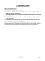
1. INTRODUCTION
About this Manual
This manual is divided into four chapters:
1. Introduction: this describes the parts of an Intruder Alarm System (IAS)
based on the 9651 control unit.
2. Technical Description: this defines the operating parameters of the different
parts of the system.
3. Installation: this explains the tasks involved in installing an IAS using the
9651 control unit.
4. Programming: this explains how to enter and exit programming, and lists
the commands available to the installer.
The control unit is designed to be fully programmable to suit individual user
and site requirements. Installers can program units from the keypad, entering
instructions using the three-digit commands described in Programming.
11772232
Page 1
1. Introduction
9651
Features of the Control Unit
The control unit provides:
° On-board connections for 8 Fully Supervised Loop (FSL) zones or 8
Closed Circuit Loop (CCL) zones with a common tamper.
° Connections for 3 fully programmable panel outputs.
° A 4-wire bus for keypads.
° Internal sounder loudspeaker output with Chime, Alarm, Fire and Entry/Exit
tones (the volume of the Entry/Exit and Chime tones can be adjusted).
° 8 programmable plug-by outputs (for connecting a standalone
communication device).
° Fully programmable operation for zones and levels.
° Installer-programmable Engineer Code.
° Support for up to 50 separate users.
User facilities include:
° 4 different security levels, which can be programmed by the Installer as a
full set and 3 part sets.
° Proximity tag reader for setting and unsetting the system.
° Dual key alarms from the keypads (Panic Alarm, Medical and Fire).
° Remote Panic Alarm input to 9940 keypad.
° User-programmable Duress Code.
Test facilities include:
° 700-entry event log.
° Output test commands.
° Engineer walk test command.
Page 2
11772232
9651
1. Introduction
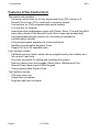
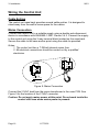
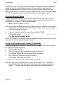
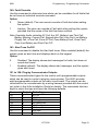
Elements of the IAS
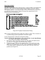
An IAS comprises a control unit in a shielded case, with 1 to 4 separate
keypads and various detectors or other devices, for example keyswitches,
connected to programmable zones.
The control unit has eight zone connectors on its printed circuit board (PCB).
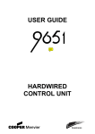
Figure 1 shows how these elements are connected. In this example, the
control unit (1) is directly connected to 6 detectors (3) and 2 door contacts (4).
There are 4 keypads (2) on the bus.
1 - Control unit
2 - Keypads
3 - PIRs
4 - Door contacts
5 - fused mains spur
Figure 1. Elements of an Intruder Alarm System
11772232
Page 3
1. Introduction
9651
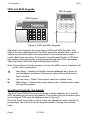
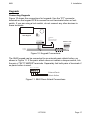
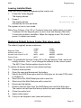
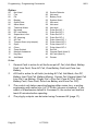
9930 and 9940 Keypads
9940 Keypad
9930 Keypad
A
B
C
1
2
4
5
6
7
8
9
D
3
0
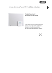
Figure 2. 9930 and 9940 Keypads
The control unit supports the connection of 9930 and 9940 keypads. The
9940 is the later replacement for the 9930, and offers smaller size, a built-in
wide-area proximity reader and connections for an external panic alarm
switch. Both have a two-line 16-character Liquid Crystal Display (LCD) that
can display alarm information, programming settings and other information.
There are three LEDs that have the following functions.
Note: Depending on how the system is set up, the LEDs may not operate until
a user code is presented.
Alert lamp – Flashes to highlight unacknowledged alert, glows for
acknowledged conditions, and goes out when all conditions have
been rectified.
s
Service lamp – Glows if the system needs an installer reset.
a
Mains lamp – Glows when using mains power. Flashes when using
the stand-by battery.
ScanProx Proximity Tag Reader
The ScanProx 934EUR-50 proximity reader module enables you to convert
9930 keypads into proximity tag readers. The module fits onto connector pins
on the keypad PCB, near the display module (Figure 6).
Once the ScanProx module is fitted, users can operate the alarm system by
presenting a tag to the front of the keypad instead of keying in an access
code.
Page 4
11772232
9651
1. Introduction
User Control
The control unit provides 50 independent User access codes and a separate
Duress Code. Users can change these codes at any time but cannot use
them to program the system. During installation, the Installer can select
whether access codes use four or six digits.
Users can set only one level at a time. Level A sets the whole system. Levels
B, C and D set parts of the system. The Installer allocates zones to levels, but
all keypads operate the entire system. There is only one sounder output for
the whole system, and you can use a loud-speaker for setting tones and local
alarms. All users belong to the whole system.
11772232
Page 5
1. Introduction
9651
(This page is intentionally blank.)
Page 6
11772232
2. TECHNICAL DESCRIPTION
Control Unit Specification
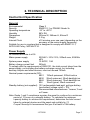
General
Environmental
Security
Operating temperature
Humidity
Dimensions
Weight
Internal Clock
Class 2
EN50131-1 or PD6662 Grade 2x
-10° to +55°C
96% RH
235mm W, 245mm H, 90mm D
3.3 kg
±10 minutes over one year (depending on the
accuracy of the mains supply frequency).
Suitable for use in a system that is designed to comply with EN50131-1,
ACPO-IAS Policy, NSI NACP14.
Power Supply
All currents accurate to ±5%.
Mains power supply
230VAC +10%/-15%, 200mA max, 50/60Hz
±5%
System power supply
13.8VDC, 1.0A
Battery charge current limit
250mA
To comply with the requirements of EN50131, the total current taken from the
power supply, not including the battery recharge current, but including
auxiliary outputs and other devices, must not exceed 750mA.
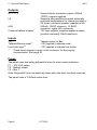
Nominal power requirements (DC):
9651 130mA quiescent, 220mA active
9930 20mA quiescent, 35mA backlight on
9940 30mA quiescent, 70mA backlight on
934
15mA typical, 20mA maximum
Standby battery (not supplied) 12V rechargeable lead-acid, gel-type battery.
Low battery voltage cutoff = 10V.
Recommended manufacturers: Yuassa, Yucel
or Fiamm.
Note: Grade 1 and 2 compliance requires the panel to continue for a minimum
period of 12 hours on a standby battery. To calculate the minimum
capacity battery to achieve this requirement, determine the total current
taken by external devices and the panel and multiply by 12.
Cooper Security Ltd recommend that you fit at least a 7Ah battery.
11772232
Page 7
2. Technical Description
9651
Outputs
OP 1, 2, 3
LS
AUX
Communications outputs
Open-collector transistor outputs, 500mA,
12VDC, negative applied.
Supports two parallel-connected, externally
mounted loudspeakers for internal sounder or
EE tones: minimum speaker impedance 8Ω.
500mA, 12VDC minimum, 13.8VDC
maximum, ripple ±2% maximum.
12V logic outputs, negative applied in alarm
(positive removed), 50mA maximum.
Inputs
TR
Tellback/Remote reset**
Line Fault input**
**
Tamper return for Bell
+12V applied to operate reset.
+12V applied to indicate line failure.
These inputs appear as pins on the connector for the plug-by
communicator. See page 25.
Fuses
The panel uses fast-acting polyswitch fuses for overcurrent protection:
F1 – 12V AUX output
F2 – Battery output
F3 – Bus 1
Note: Polyswitch fuses automatically reset when the load is entirely removed.
The panel uses a T-250mA mains fuse.
Page 8
11772232
9651
2. Technical Description
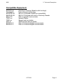
Compatible Equipment
934EUR-50
Proxtagpk5
9930EUR-50
9940EUR-50
660xx-00
TSD1+xx
TSD2-xx
SD3-xx
8400UK-21
8440UK-21
ScanProx Proximity Module (with two tags)
Pack of five proximity tags
9930 LCD Keypad (ScanProx-compatible)
9940 LCD Keypad with built-in Proximity Reader
Wire-in speech communicator
Speech Dialler
Speech and text dialler
GSM speech and text dialler
Wire-in 8-channel digital communicator
Wire-in 4-channel digital communicator
11772232
Page 9
2. Technical Description
9651
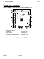
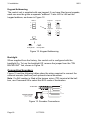
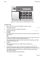
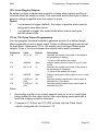
Control Unit PCB Layout
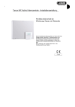
Figure 3 shows the layout of the PCB used in the control unit.
1. Power input: 12vdc battery and 21vac
from transformer (pre-wired)
2. Kick Start pins
3. Zone connectors
4. AUX power
5. Outputs (3 open collector outputs)
6. Tamper return from external sounder
7. Speaker connector
8. Keypad connector
9. NVM Reset pins
10. Plug-by (standalone) communicator connector
11. Processor in socket
12. Lid tamper switch
Figure 3. Control Unit PCB Layout
Page 10
11772232
3. INSTALLATION
Caution: Always remove mains power before opening the case lid. Do
not work inside the control unit with mains power present.
Overview
A typical installation comprises the following main steps:
1. Survey the site and decide on positions for wired detectors, control unit,
keypads, external and internal sounders. As part of the survey ask the
users what facilities they need.
2. Ensure that there is a suitable mains supply present at the site of the
control unit.
3. If you are going to use a communicator, arrange for a PTT (Public
Telephone and Telegraph) connection point near to the control unit.
4. Install the wired detectors and run cables to the site of the control unit.
Connect each detector to its cable.
5. Run cables from the sites of the keypads, external and internal sounders
to the site of the control unit.
6. Install keypads and connect them to their cabling. Ensure that each one
has the correct address setting. If necessary, install 934 ScanProx
modules on the keypads.
7. Install internal and external sounders and connect them to their cabling.
8. Install the control unit and connect it to the mains supply cabling. Do not
apply power at this point.
9. At the control unit, complete all connections to detectors, keypads and
sounders.
10. Apply power and program the control unit.
11. Test that the intruder alarm system operates as required.
12. If required, install a communicator, connect it to the PTT network and
check that it operates correctly.
13. Hand the system over to the users and instruct them in its use.
11772232
Page 11
3. Installation
9651
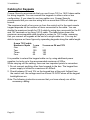
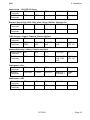
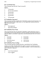
Cabling for Keypads
Cooper Security recommends that you use 8-core 7/0.2 or 16/0.2 alarm cable
for wiring keypads. You can connect the keypads in either a star or bus
configuration. If you intend to use long cable runs, Cooper Security
recommends that you use star wiring with no more than 200m of cable per
branch.
The maximum length of any one run from the control unit to the most remote
keypad depends on the number of items connected to the cable. You can
double the maximum length for 7/0.2 cable by using two cores each for the 0V
and 12V terminals or by using 16/0.2 cable. The table below shows the
maximum recommended cable lengths in metres for 7/0.2 cable, assuming
that you connect all keypads at the end of a single cable run. You may be
able to improve on these figures by spreading keypads along the cable length.
8-core 7/0.2 cable
Number of kpds
One
Two
Three
Four
1 core
200
100
65
50
2 cores on 0V and 12V
–
200
130
100
It is possible to extend the keypad cable run by using additional power
supplies, but only up to the recommended maximum of 200m.
When carrying out the cabling, there are two important points to remember:
1. Do not connect anything other than keypads to the bus. The keypad bus
power supply is limited to a maximum of 400mA.
2. Check between 0V and 12V on the keypad bus at the point furthest from
the control unit: the voltage must be at least 12.0VDC when all the keypad
backlights are on.
Note: The following instructions assume that you have already run all the
necessary cabling.
Page 12
11772232
9651
3. Installation
Fitting the System
Fitting the Control Unit Case
1.
2.
3.
4.
Remove the control unit case from its packaging.
Remove the front screws and slide off the case lid.
The upper part of the case back has a central keyway. Mark and drill a
hole for the keyway. Temporarily fix the case back to the wall. Mark the
position of two more fixing holes, remove the case back and drill the
holes.
Refit the case back to the wall using screws no less than 30mm x No 8,
with dome or pan heads.
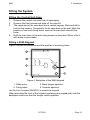
Fitting a 9940 Keypad
Figure 4 shows the backplate and the position of mounting holes.
4
3
Figure 4. Backplate of the 9940 Keypad
1. Cable entry.
3. Back tamper aperture.
2. Fixing holes.
4. Sounder aperture.
Use No 8 or 6 screws (M4/M3.5) to mount the keypad.
When mounting the front of the keypad (containing the keypad pcb) onto the
backplate make sure that the tamper switch operates.
11772232
Page 13
3. Installation
9651
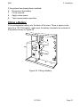
Fitting a 9930 Keypad
The backplate of the 9930 keypad (see Figure 5) contains an adjustable cam
that you can use to make sure the tamper switch will operate correctly when
the keypad is mounted on an uneven surface.
Cooper Security recommends that you mount the keypad using No 8 or 6
screws (M4/M3.5) as follows:
1. Remove the front cover by first releasing the screw located on the
bottom edge of the keypad.
2. Select which cable entry you are going to use and break out the
appropriate plastic sections.
3. Hold the backplate in place against the wall and mark the position of the
centre hole in the adjustable cam (item 2 in Figure 5).
4. Drill and plug the hole, and screw the backplate to the wall through the
adjustable cam. Do not tighten the screw completely home.
5. Make sure the backplate is level. Mark, drill and plug at least two more
fixing holes (item 1 in Figure 5). Screw the backplate to the wall through
the holes.
6. Cut the plastic webs connecting the cam to the backplate.
Note: If you do not cut the webs, the tamper switch will not operate in the
event of the complete keypad being forced off the wall.
7.
8.
Attach the front cover of the keypad (containing the keypad PCB) onto
the backplate and make sure that the tamper switch operates.
If the tamper switch does not operate, rotate the cam until the switch
operates correctly with the front of the keypad mounted on the backplate.
1
1
2
1
1
1. Fixing hole
2. Adjustable cam
Figure 5. Backplate of the 9930 EUR Keypad
Page 14
11772232
9651
3. Installation
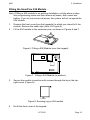
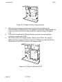
Fitting the ScanProx 934 Module
Note: If fitting a 934 module to an existing installation, put the alarm system
into programming mode and then remove all power, both mains and
battery. If you do not remove all power, the system will not recognise the
934 module.
1.
2.
Remove the front cover from the keypad(s) to which you intend to fit the
module. Remove the cable clips (item 4 in Figure 5).
Fit the 934 module to the connector pins, as shown in Figures 6 and 7.
Figure 6. Fitting a 934 Module (over the keypad)
Figure 7. Fitting a 934 Module (in position)
3.
Secure the module in position with a screw through the lug in the topright corner (Figure 8).
Figure 8. Securing lug on 934 module
4.
Re-fit the front cover of the keypad.
11772232
Page 15
3. Installation
9651
Wiring the Control Unit
Cable Entries
The control unit case back provides several cable entries. It is designed to
stand away from the wall to leave space for the cables.
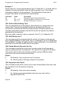
Mains Connection
Connect the control unit to a suitable supply using a double pole disconnect
device in accordance with EN60950-1:2001 Clause 3.4.3. Connect the supply
to the control unit using the 3-way terminal block located on the case back.
Secure the cable to the case anchor point using the cable tie provided.
Notes:
1. The control unit has a T-250mA internal mains fuse.
2. All electrical connections should be carried out by a qualified
electrician.
To Control Panel
Transformer
L
N
230V ~50Hz 200mA
T 250mA 250V
Figure 9. Mains Connection
Connect the 21VAC lead from the mains transformer to the main PCB. See
Figure 3 for the location of the 21VAC connector.
Caution: Do not apply mains power at this point. Do not work inside the
control unit case when mains power is present.
Page 16
11772232
9651
3. Installation
Keypads
Connecting Keypads
Figure 10 shows the connections for keypads. Use the "ET" connector
terminals on the keypad PCB to connect an exit terminate button or lock
switch. If you are using a lock switch, do not connect any other devices to
these terminals.
9930 Keypad
0V12V CLK DATA ET
Lock Switch
Or
Exit terminate button
(NO, push to make)
Control Unit
0V12V CLK DATA
4-core
To other
keypads
Figure 10. Keypad Connections
The 9940 keypad can be connected to an external panic attack button, as
shown in Figure 11. If the panic attack does not contain a tamper switch, link
the pair of "EXT TAMPER" terminals. Separately link both pairs of terminals if
no panic button is used.
PANIC I/P EXT TAMPER
External Panic
Attack Button
Figure 11. 9940 Panic Attack Connections
11772232
Page 17
3. Installation
9651
Keypad Addressing
The control unit is supplied with one keypad. If you have fitted more keypads,
each one must be given a separate "address". Links LK2 to LK4 set the
keypad address, as shown in Figure 12.
Keypad 1
Address
Keypad 2
2
2
2
3
3
3
4
4
4
Keypad 3
Keypad 4
2
2
3
3
4
4
ON
BACKLIGHT
ON
BACKLIGHT
Backlight ON
ON
BACKLIGHT
Backlight OFF
Figure 12. Keypad Addressing
Backlight
When supplied from the factory, the control unit is configured with the
backlight On. To turn the backlight Off, remove the jumper from the "ON
BACKLIGHT" link, shown in Figure 12.
Connecting Sounders
Figure 13 and the following tables show the wiring required to connect the
external sounder (bell box) and optional internal sounders.
Note: If a 2k2 resistor is fitted at the tamper return (TR) terminal at the bell
box, use Command 59 to select this EOL mode of termination.
To Bell Box
OP1
6-core
OP2
TR
+
LS
12V AUX
Internal Sounder
16 Ohm Loudspeaker
(2 Max. in parallel)
0V
Figure 13. Sounder Connections
Page 18
11772232
9651
3. Installation
Lyntech Ltd - 120 LED/120 lexon
Control Panel OP1
OP2
Terminals
Bell-Box
TRG
STRB
Terminals
TR
12V AUX
0V
HOLD +
Elmdene Rapier 300, 4000, 5000, 6000; Prima 100-600; Starlight 020
Control Panel OP1
OP2
TR
12V AUX
0V
Terminals
Bell-Box
-R
-ST
RTN
+H
-H
Terminals
CQR Security - Sigma, Cequera, Plus and Ultima
Control Panel OP1
OP2
TR
Terminals
Bell-Box
SIREN
STROBE
A/T RET
Terminals
TRIG
TRG
SIG
Ventcroft Security - Vision, Classic and Spirit
Control Panel OP1
OP2
TR
Terminals
Bell-Box
TRIG STB RTN
Terminals
Flashguard - Xtra
Control Panel OP1
Terminals
Bell-Box
TRIGGER
Terminals
Intellisense - AG3
Control Panel OP1
Terminals
Bell-Box
STerminals
12V AUX
0V
HOLD OFF
+VE
HOLD
OFF -VE
12V AUX
0V
HOLD OFF
+VE, STB
+VE
HOLD
OFF -VE
OP2
TR
12V AUX
0V
STROB-
SUPPLY -
SUPPLY +
STROBE +
TAMP
OUT
OP2
TR
12V AUX
0V
ST-
TR
V+
V-
11772232
Page 19
3. Installation
9651
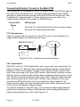
Connecting Detector Circuits to the Main PCB
The connectors for the detector circuits, or zones, are on the left-hand edge of
the main PCB in the control unit. The table below summarises the number
and type of zones that can connect to the main PCB of the control unit. Use
Command 21 to specify which of these wiring types you are using. You
cannot specify different wiring types for different zones.
Control Unit
Zones
8
8
Wiring Type
four-wire CCL (closed circuit loop) with common tamper
two-wire FSL (fully supervised loop)
CCL Connections
Figure 14 shows how to connect four-wire CCL zones. Note that there is a
single Global tamper loop that serves all zones.
Tamper loop
Global Anti-tamper
Zone 1
Zone 2
Alarm contacts
Zone 1
1
2
Zone 3
Zone 4
Zone 5
Zone 6
Alarm contacts
Zone 7
Zone 8
Zone 2
Figure 14. CCL Connections (common tamper)
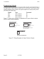
FSL Connections
Each FSL zone is a "Fully Supervised Loop" using a two-wire closed loop. As
shown in Figure 15, the loop uses resistors of different values to differentiate
between "Circuit" and "Tamper" signals: a 2K2 resistor fitted in series at the
end of the wired loop (EOL) and a 4K7 resistor fitted across the alarm contact.
With the loop in a normal state and the alarm contacts closed (shorting out the
4K7 resistor), the total resistance of the loop is 2K2. When the alarm contacts
open (removing the short from the 4K7 resistor), the resistance of the loop
increases to 6K9 and so the control unit detects an alarm condition. If a
tamper device opens, the loop resistance becomes infinite (open circuit) and
so the control unit detects a tamper signal.
To connect a detector to an FSL loop, you must wire suitable high-tolerance
resistors to the detector. Always check resistor colour coding and tolerance
before wiring resistors into circuit (see Figure 16).
Page 20
11772232
9651
3. Installation
The wiring resistance of the cable to the detector (including joints) should not
exceed 100 ohms. The recommended maximum cable length within a zone is
200–300m.
Figure 15. FSL Connections
4k7
Yellow
Violet
Red
Gold
2k2
Red
Red
Red
Gold
Figure 16. Colour Code for FSL Resistors
11772232
Page 21
3. Installation
9651
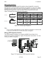
Programming Outputs
Control unit panel outputs can be programmed using the commands shown in
the table below. Open collector outputs are of a "pull down" type that provides
negative-applied control signals; the system adjusts the output polarity when
you select the output type.
Output
OP1
OP2
OP3
Type
open collector
open collector
open collector
Command
81
82
83
Figure 17 shows some examples of applications for open collector outputs
(OP3 is used in these examples).
Shock Sensor Reset
VIPER
0V
Bell Follow Buzzer/Relay
OP3
OP3
BUZZER/RELAY
+ve
+ve 12V Aux
+ve 12V Aux
Use Command 83 4
Use Command 83 0
Relay energises/buzzer sounds
when bell activates.
PIR Set Latch/Walk Test
PIR
OP3
For:
Set Latch use Command 83 3
Walk Test use Command 83 5
Figure 17. Wiring Examples for Open Collector Outputs
Page 22
11772232
9651
3. Installation
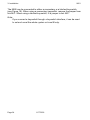
Wiring Keyswitches
To allow a user to set and unset the system using a keyswitch, connect a
fixed position or spring loaded (momentary) key switch to a zone input. When
programming the control unit select zone type (KM) for momentary or (KF) for
fixed position keyswitches. See Command 185 for keyswitch auto-reset.
Figure 18 shows the connections for a keyswitch.
Fixed Keyswitch (KF)
Keyswitch
CC
FSL
System
CC Wiring
CCT(n)
OFF
Closed
2k2
Unset
ON
Open
6k9
Set
Momentary
Keyswitch
(KM)
4k7
Keyswitch
CC
FSL
System
Operate
Close-Open- 2k2-6k9-2k2
Unset
FSL Wiring 2k2
Close
CCT(n)
Operate
Close-Open- 2k2-6k9-2k2
Set
Close
Figure 18. Connecting a Keyswitch
Note:
If you connect a keyswitch as a zone, without an interface, it can be used
to set and unset the level to which the zone is assigned.
Wiring a 9928 Keyswitch Interface
The 9928 keyswitch interface is no longer available for purchase, but is
supported in existing installations. Figure 19 shows the connections. You can
fit only one 9928 in a system.
To keypad bus
on control unit.
Latched
9928
0V
Full
12V
COM
Off
CLK
KS2
Part
DATA
KS1
ET
RDY
Momentary
Full
PA
SET
Part
TAMP
M/C
Momentary
M/C
Continuous
M/C
Figure 19. Connecting a 9928 Keyswitch Interface
11772232
Page 23
3. Installation
9651
The 9928 can be connected to either a momentary or a latched keyswitch
(see Figure 19). When using a momentary keyswitch, remove the jumper from
link M/C. When using a latched keyswitch, fit a jumper to link M/C.
Note:
If you connect a keyswitch through a keyswitch interface, it can be used
to set and unset the whole system or Level B only.
Page 24
11772232
9651
3. Installation
Communicator
The 9651 can be fitted with a communicator or speech dialler, for example the
Scantronic 660, 8400, and 8440 digital communicators or the SD1, SD2 or
SD3 Speech diallers. To connect an SD1, SD2 or SD3 follow the instructions
provided with those products. Figure 20 shows the connections for the
communications wiring harness.
Figure 20. Plug-By Communicator Wiring
Note: Comms O/P4 will be active when the system is unset. This is normal, as
a system being unset is equivalent to an alarm signal.
To fit a communicator, follow the instructions below.
Caution: Follow the instructions in the order shown, or you may damage
the control unit and/or communicator.
1. Disconnect mains and battery power from the control unit and remove
the case lid, if the system has already been installed.
2. Detach the main PCB from the support pillars in the control unit case,
and lift the PCB carefully to the left. Fit the communicator between the
PCB support pillars, making sure that the main PCB can fit back into
position (see Figure 21).
11772232
Page 25
3. Installation
9651
Figure 21. Fitting a Plug-by Communicator
3.
4.
5.
Make any necessary connections from the communicator to the
communication wiring harness. The default is a positive voltage when the
output is inactive but this can be inverted if required using Command
159.
Plug the Communication Wiring Harness onto the communications
connector on the main PCB.
Re-fit the PCB to the support pillars. Secure the PCB to the support
pillars with the screws provided (Figure 22). Make sure that the bottom
left corner of the PCB is seated on its support pillar.
Figure 22. Fitting Control Unit PCB
Page 26
11772232
9651
3. Installation
If the system has already been installed:
6. Re-connect the battery.
7. Fit the case lid.
8. Apply mains power.
9. Test communicator operation.
Fitting a Battery
Fit a rechargeable battery into the back of the case. There is space in the
case for a 12V 7Ah battery; make sure the battery terminals are oriented in
the position shown in Figure 23.
7AH
Figure 23. Fitting a Battery
11772232
Page 27
3. Installation
9651
Initial Start Up
Before applying power to the control unit, ensure that:
• All keypads have been addressed and connected.
• All external and internal sounders are connected.
• All wired zone circuits are connected.
Then:
1. Connect the battery to the control unit PCB.
2. Briefly short the Kick Start pins together (see Figure 3).
The internal sounder may sound. Ignore any display at this stage.
3. Key in the factory default User access code: 1234.
The internal sounder stops. Ignore any display or lamps.
4. Fit the case lid before applying mains power (this covers the live wiring
and closes the tamper switch).
5. Apply mains power.
6. Key in 0 followed by the factory default Engineer Code: 7890.
Note: You do not have to remove the case lid.
The display shows:
Installer Mode
You are now in installer (programming) mode.
The Programming Guide explains how to program the system.
Page 28
11772232
4. PROGRAMMING
Introduction
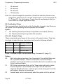
This chapter is divided into four sections:
1. Introduction provides an overview of how to program a 9651 control unit.
2. Programming Commands lists and describes the commands available to
program aspects of a 9651 control unit's operation.
3. Testing Commands lists and describes the commands available to test a
newly installed alarm system based on a 9651 control unit.
4. System Configurations describes how to set up a 9651 control unit so
that it complies with industry standards.
The 9651 control unit is fully programmable to accommodate individual user
and site requirements. Installers program units from the keypad. Enter
instructions using the two and three-digit commands described in
"Programming Commands". Before you start, familiarise yourself with the
control unit's functions and the programmable options described in this
manual.
For guidance on using 9651 control units, refer to the 9651 User Guide.
Operating Modes
The alarm system has three basic modes of operation that provide access to
commands appropriate to different types of users:
1. User mode allows setting, unsetting and resetting of the system, along
with some basic commands. There may be many user codes of this type.
2. Master user mode provides access to all user commands, including those
available in user mode. The master user can configure other users. There
is only one user code of this type.
3. Installer mode provides access to the installer menu, which contains the
programming and testing commands described in this Guide. There is only
one user code of this type.
To enter either of the user modes, enter a user code (which may be four or six
digits) or present a proximity tag. To select a user command, enter the
command number.
To enter installer mode, enter zero followed by the installer code (which may
be four or six digits). To select an installer command, enter the command
number.
11772232
Page 29
Programming
9651
In addition to the three standard operating modes, there is a special Duress
mode which provides the same access as user mode but also secretly
communicates the duress status. There is only one user code of this type.
See Command 49 for details on how to enable Duress Code, and Commands
151-158 for details on how control the plug-by communicator outputs.
Entering Installer Mode
Chapter 3 describes how to enter installer mode for the first time in a new
installation. You can use this mode at any time, provided that the system is
unset and not in alarm. To enter installer mode:
1. Make sure the system is unset.
Note: If you have selected defaults for Finland, Norway, Sweden or Denmark
(Command 0), or a user has selected user command 3, you must enter a
valid user code at this point.
2.
Press 0, then key in the Engineer Code (default 7890).
The display shows:
Installer Mode
You are now in installer mode.
While the system is in installer mode, all keypads except the one that you are
using will be locked and will display "Busy".
Using Programming and Testing Commands
When delivered from the factory, the control unit already has default settings.
To change the default settings:
1. Enter installer mode.
2. Key in the appropriate command number and press y.
The display shows the current value of the command.
3.
Key in digits to select the value you require.
The display shows the new value.
4.
Press y to store the new value of the command.
Note: If at any time you change your mind, repeat steps 1 to 3. The 9651
Quick Reference Programming Guide shows the commands and their
values. "Y" to the right of a value shows that it is the factory default.
Page 30
11772232
9651
Programming
Leaving Installer Mode
When you have finished programming the control unit:
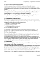
1. Press 99y at the keypad
The display shows:
2.
Press y.
The display shows:
followed by the time and date.
99:Exit Eng ?
99:Checking Sys
The system is now in user mode.
Note: If any 24-hour, Fire, PA or Technical zones are active when you enter
Command 99, the keypad gives an error tone and displays the faults.
Correct the problems identified. When the display shows "No Faults",
press y to enter user mode.
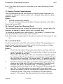
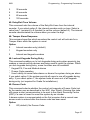
Restoring Default Access Codes (first stage reset)
The default (original) access codes are:
Engineer Code
Access Code User 1
Access Code Users 2 to 50
Duress Code
4-digit
7890
1234
X002 ... X050
X051
6-digit
567890
123456
X00002 ... X00050
X00051
Note: To activate the Access Codes (02 to 50) and Duress Code, which are
initially inactive, User 1 must change the defaults to the correct codes.
The 9651 User Guide explains how to do this.
To restore all access codes to their default settings:
1. Remove mains power.
2. Open the case and disconnect the battery.
3. Identify the NVM Reset pins and Kick Start pins on the main PCB (refer
to Chapter 3).
4. Short circuit the NVM Reset pins with a wire link.
5. Short circuit the Kick Start pins with a wire link.
6. Reconnect the battery.
7. Remove the wire links from the NVM Reset pins and Kick Start pins.
The control unit will load the factory default access codes listed above.
8. Close the control unit.
9. Apply mains power.
10. Carry out an engineer reset (see next section).
11772232
Page 31
Programming
9651
Performing an Engineer Reset
To perform an engineer reset:
1. Check that the display is showing the alarm condition.
2. Enter installer mode.
3. Enter 99 yy.
The display returns to the time and date.
Restoring Default Command Settings
To restore all command options to their default (original) settings:
1. Enter installer mode.
2. Press 98y at the keypad.
The display shows:
Load Default
3.
Press 1y at the keypad.
The keypad gives a double "beep" confirmation tone and the control unit
loads the default settings, erasing all previous selections.
Adding and Deleting Tags
You can use any industry-standard ISO tag or card with the 934 module. To
purchase tags from Cooper Security, quote part number Proxtagpk5.
A tag acts as an alternative to a user access code. You can assign a user a
tag, an access code, or both. You cannot assign a tag to the Master User
(User 01) or the Installer (User 00). This means you can assign up to 49 tags
on a system, one each for Users 2 to 50.
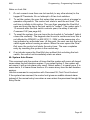
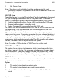
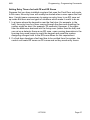
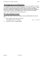
When presenting a proximity tag to a 9930 keypad, whether for programming
or for normal use, make sure that the tag is touching the front of the keypad to
the left of the display as shown in Figure 24. The 9940 keypad has a proximity
coil that makes the whole case sensitive to tags.
Page 32
11772232
9651
Programming
Figure 24. Sensitive Area on 9930 Keypad for Tag
To Add a Tag
1.
2.
Key in User 01 access code while the system is unset.
The display shows:
Press 4 to select the change codes option.
The display shows:
Select?
Old Code=
3.
EITHER
Enter the access code of the user for whom you want to program a tag
and press y.
OR
Press X repeatedly until the display shows the user number of the user
for whom you wish to program a tag and press y.
The display shows the user number and any text description you have
programmed for that user.
4.
Press y.
The display shows the user number and an underscore,
for example:
User 06 =
5.
_
_ _ _
Present the proximity tag to the front of the keypad (see Figure 24).
The system learns the identity of the tag and links it to that user number.
The keypad gives a double "beep" to confirm that the tag has been
learned successfully.
The keypad displays the date and time.
11772232
Page 33
Programming
6.
9651
Repeat steps 1 to 5 for other tags, as necessary.
To Delete a Tag
Note: If you delete a tag, you also delete that user's access code.
1.
2.
3.
Key in User 01 access code while the system is unset.
The display shows:
Press 4 to select the change codes option.
The display shows:
Select?
Old Code=
Enter the User 01 access code again and press y.
The display shows "User 01" and any text description for that user.
4.
The display shows the user number and any text you have programmed
for that user.
5.
6.
Press y.
Key in "0000" and press y.
The system deletes the tag and the user's access code. The keypad
gives a double "beep".
Page 34
11772232
_
Programming - Programming Commands
9651
Programming Commands
0: Country PTT Defaults
Use this command to select the country and PTT (Public Telegraph and
Telephone) defaults; it also loads default access codes and programming
options. Use Command 126 to select language without making other
changes.
Note: If you select options X4, X5, X6 or X7 (Finland, Norway, Sweden or
Denmark), the control unit changes the method of entering installer mode
(see "Entering Installer Mode" on page 29).
Option
0
1
2
3
4
5
UK (default)
Italy
Spain
Portugal
Netherlands
France
Option
6
7
8
9
X1
X2
Belgium
Germany
Switzerland
Austria
Ireland
OEM 1
Option
X3
X4
X5
X6
X7
OEM 2
Finland
Norway
Denmark
Sweden
01 to 08: Zone Programming
There are eight zones available on the 9651 control unit. Key in "01" to "08"
and press y. The zone programming commands take at least three further
digits: the first two specify the zone's type, while the others specify the zone's
attributes.
When you key in the zone number and press y, the display shows the zone
number and any text associated with it. At this point, you can edit the zone
text. When the text is as required, press y to display the zone type and
attributes. At this point, you can edit them. When they are as required, press
y once more to store the changes.
Zone Names
When you key in the zone number and press y, the display shows the current
zone name with a flashing cursor under the first letter. Zone names can
contain up to 12 characters, including spaces and punctuation marks.
Enter letters from the keypad one at a time by repeatedly pressing a number
key until the display shows the letter you want. If you make a mistake, press C
or D to move the cursor to the letter you want to change and key in the new
letter. To delete a name completely, press D to move the cursor onto the first
character of the name and then press D again to clear the old name.
When you have finished entering the name, press y.
Page 35
11772232
Programming - Programming Commands
9651
The following table shows the letters generated by each key on the keypad.
1
2
3
4
5
6
ABCÆÅÄ
DEF
GHI
JKL
MNOØÖ
7
8
9
0
C
D
PQRS
TUV
WXYZ
Space ' ( ) : . - ! &
Move right
Move left
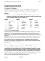
Zone Types
The following table shows the values available for zone type.
Value
00
01
02
03
04
05
06
07
Page 36
Type
Not Used
(NU)
Description
Identifies zones that are not used. The system ignores zones of
this type. It is not necessary to link the circuit or anti-tamper
connections.
Panic Alarm
Operating a device programmed as "Panic Alarm" will start
(PA)
either a silent alarm transmission to the Alarm Receiving Centre
(ARC) or an audible alarm, depending on how you have
programmed PA Response (see Command 30). PAs operate,
whether the system is set or unset.
Fire (FR)
Smoke or heat detectors connected to FR type zones cause the
speakers to give a distinctive fire signal (internal sounders
pulsing "Dee Dah Dee Dah..."). Fire alarms always operate,
whether the system is set or unset, and always trigger
communications if fitted.
Normal Alarm A zone programmed as "Normal Alarm" will start an alarm if
(NA)
activated while the system is set.
24-hour (24)
This zone causes an internal alarm if violated when the system
is unset, and a full alarm if the system is set. If the Installer
programs 24-hour zones with "Omit Allow", the user can omit
24-hour zones in Day mode. The control unit reinstates all 24hour zones if anyone sets the system.
Final Exit (FE) Zones of this type must be the first to be activated on entry. You
can use them to set the system using the Final Door Set exit
mode. Use Command 39 to set the exit mode for the zone (page
44). Use zone attribute X7 to select an entry timer for the zone
(page 39) and Commands 201–4 (page 65) to set up the entry
timers.
Entry Route
Use this zone type for detectors sited between the Final Exit
(ER)
door/detector and a keypad. If an "Entry Route" zone is violated
when the system is set, an alarm will occur. If the Entry/Exit
timer is running when an Entry Route zone is violated, no alarm
occurs until the Entry/Exit timer expires. Use zone attribute X7 to
select an entry timer for the zone (page 39) and Commands
201–4 (page 65) to set up the entry timers.
Shock
You can apply this zone type to zones 1 to 4. The system will
Analyser (SA) not accept this type for zones 5 to 8. Use zone attribute X7 to
set the sensitivity for the zone (page 39).
11772232
9651
Programming - Programming Commands
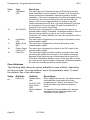
Value
08
Type
Technical
Alarm (TC)
09
Keybox (KB)
10
Smoke
Detector (SD)
11/12
Keyswitch
13
Anti-Mask
Zone (AM)
Description
Use this zone type when you want to monitor equipment, for
example a freezer, without raising a full alarm. If a Technical
Alarm zone is activated while the system is set, the system
makes no audible alarm. However, when a user unsets the
system, the keypad indicates a fault. If a Technical Alarm zone
is activated while the system is unset, the system starts a pulsed
tone from the keypad. If programmed, the control unit also starts
communication. When a user enters a valid code, the keypad
stops the tone and displays the zone.
This zone type is for use in Scandinavia only. When a zone of
this type is required, the Installer connects the alarm wires of the
zone to a special external key box and the tamper wires to the
box enclosure switch. When someone opens the box, the
control unit logs the event and communicates it to the Alarm
Receiving Centre (ARC). The control unit also provides a Key
Box output type, which you can program with Command 151 to
trigger one of the plug-by communicator output pins.
In Scandinavia only, use this type for zones connected to 12V
smoke detectors. This type is active whether the system is set or
unset, and the control unit will transmit a specific alarm to the
Alarm Receiving Centre (ARC) if triggered. The control unit also
provides a Smoke Detector output type, which you can program
with Command 151 to trigger one of the plug-by communicator
outputs. If a zone of this type causes an alarm, the user will
need to enter an access code to disarm and reset the system.
There are two Keyswitch zone types: Momentary and Fixed.
Use these for zones that connect to an access control keypad,
electronic key or other hardwired device used to set or unset the
system:
11
Momentary Keyswitch (KM)
12
Fixed (or latched) Keyswitch (KF)
The keyswitch or similar device can be used to set and unset
the level to which the zone is assigned. It cannot be used to
reset the system.
In a single system, do not assign a Keyswitch zone to levels B,
C or D if you have assigned one to Level A (full system).
Use this zone type for the anti-mask outputs of detectors with
this facility. Connect the detector's alarm and contact wiring to
one zone (for example, Zone 07) and its anti-mask outputs to
the zone above (for example, Zone 08). Assign the Anti-Mask
type to the higher zone; that is, the one connected to the antimask outputs (Zone 08 in the example).
If an Anti-Mask zone is violated, the control unit starts a Tamper
Alarm and shows the message "AM Tamper" on the keypad
display. It logs the event to the zone connected to the detector's
alarm and contact wiring (Zone 07 in the example). Command
136 defines whether an Anti-Mask zone can be reset by a user
or only by the installer.
11772232
Page 37
Programming - Programming Commands
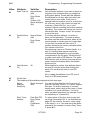
Value
14
Type
Forbikobler
(FB)
15
AC Fail (AC)
16
Low Battery
(LB)
Battery Fault
(BF)
Power Output
Failure (PF)
Fault (FL)
17
18
19
9651
Description
This zone type is a Scandinavian type of Entry/Exit zone (the
word "forbikobler" means "bypass" in Danish). Use this type for
zones connected to standalone external keypads or access
controllers. If the zone is triggered by the external keypad during
the exit time, the control unit stops the exit time and sets the
system. If the zone is triggered while the system is set, the
control unit starts the entry time. Use zone attribute X7 to select
an entry timer for the zone (page 39) and Commands 201–4
(page 65) to set up the entry timers.
This zone type is triggered by a failure in the AC input to an
external power supply. Command 134 defines whether a zone of
this type can be reset by a user or only by the installer.
Command 137 defines whether the user can override the fault to
set the system.
This zone type is triggered by a low voltage in the battery in the
external power supply.
This zone type is triggered by a fault in the battery in the
external power supply.
This zone type is triggered by a failure in the DC output to the
external power supply.
This zone type triggers a fault condition, causing an alert and
preventing the system from being set. The tamper connection
operates in the same way as a normal alarm zone (type "NA").
Command 139 defines whether a zone of this type can be reset
by a user or only by the installer. Command 140 defines whether
the user can override the fault to set the system.
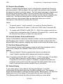
Zone Attributes
The following table shows the values available for zone attribute, depending
on the zone type. To set an attribute, key in the appropriate value. To unset
the attribute, key in the value again.
Value
Attribute
Valid for
Description
X1
Chime (C)
Normal Alarm
(NA)
Final Exit (FE)
Entry Route
(ER)
Shock Analyser
(SA)
When enabled by the user, the system makes
a doorbell-like sound when any zones
programmed as "Chime" are opened. This
facility operates only while the system is
unset.
To make the Chime available from keypad
sounders but not internal sounders, use
Command 22 with option 0.
Page 38
11772232
9651
Programming - Programming Commands
Value
Attribute
Valid for
Description
X2
Soak Test (S)
Normal Alarm
(NA)
Entry Route
(ER)
24-hour (24)
Shock Analyser
(SA)
X3
Double Knock
(D)
Normal Alarm
(NA)
Entry Route
(ER)
X4
Omit Allowed
(O)
All
Use this zone attribute if you want to place on
long-term test a detector that you suspect is
giving false alarms. Zones with this attribute
are disabled for 14 days after you return the
control unit to user mode. If the zone is
opened while the system is set (or at any time
for a 24-hour zone), the control unit logs the
event as a "Soak Fail Znn" (nn = zone
number) without sounding any bells or starting
signalling. The control unit returns the zone to
normal use after 14 days, even if the system
is set at the time.
For zones with this attribute, no action is
taken on first activation. To cause an alarm,
the zone must be activated twice within a fiveminute period or remain open for longer than
10 seconds. An alarm will also occur if
another double-knock zone is activated within
five minutes of the first.
Programming a zone as "Double Knock" is a
way of reducing false alarms caused by
environmental changes but is not normally
recommended. Do not apply "Double Knock"
to radio zones with a PIR detector. The radio
PIR detector uses a lockout timer and will not
send a second activation within the Double
Knock period.
When applied to a zone, this attribute allows
the user to omit the zone when setting the
alarm. Do not allow the user to omit PA
zones.
Do not apply this attribute to an FE zone if
there is no ER zone present.
X5
X7
Do Not Use.
The meaning of this attribute depends on the zone type:
Shock
Shock Analyser You can set this attribute only for a zone of
Analyser
(SA)
type SA, and only zones 1, 2, 3 and 4 support
Sensitivity
this type. To set the sensitivity of a shock
sensor zone, enter a digit in the range 1 (least
sensitive) to 6 (most sensitive). You must
enter the whole sequence; for example, to set
the sensitivity to 3, press X73
Entry Timer
Final Exit (FE)
To select which of the four entry timers (set
Number
up using Commands 201–4, as described on
Entry Route
page 65) are used for the zone, enter a digit
(ER)
in the range 1 to 4. You must enter the whole
Forbikobler
sequence; for example, to select Entry Timer
(FB)
3, press X73
11772232
Page 39
Programming - Programming Commands
9651
Value
Attribute
Valid for
Description
A
Armed in
Level A
Armed in
Level B
Armed in
Level C
Armed in
Level D
All
Always applied. The zone is armed when the
user selects Level A.
When applied, the zone is armed when the
user selects Level B.
When applied, the zone is armed when the
user selects Level C.
When applied, the zone is armed when the
user selects Level D.
B
C
D
All
All
All
20: Change Engineer Code
Note: 9651 control units support six-digit access codes as well as the standard
four-digit codes. Command 56 sets the code length.
To change the Engineer Code:
1. Make sure you are in installer mode.
2. Press 20y
The display shows:
3.
4.
5.
Key in a new Engineer Code.
The display shows:
20:Code
20:Code
xxxx
Press y
Press y
21: Zone Configuration
This command enables you to select the wiring type of the zone connectors
on the control unit PCB. The default is option 0 for all models.
0
Up to 8 closed circuit loop zones (CC + Com A/T).
1
Up to 8 fully-supervised loop zones (FSL 2K2/4K7).
22: Loudspeaker Chime
In a single system, a user may find that the Chime tone from the keypads is
not loud enough. If so, use this command to make the internal sounder give
the Chime tone as well. If you select option 0, the internal sounder emits no
tone. Select a value from 1 (quietest) to 9 (loudest) to set the Chime volume
(the default is 5). The internal sounder demonstrates the volume when you
enter the digit.
Page 40
11772232
9651
Programming - Programming Commands
23: Remote Reset Enable
Option 1 enables Remote Reset, which is designed to operate with the plugby communicator. After an alarm, the user keys in an access code to silence
the alarm but cannot reset the system. The first alarm message to display and
the Service lamp remain visible. The user contacts the Alarm Receiving
Centre (ARC), which verifies the user's identity and then sends a signal to the
control unit. The Service lamp goes out and the user can then reset the
system with any valid access code, provided that there are no faults.
Use option 0 (the default) to disable this function.
Notes:
1.
To ensure option 1 works correctly, you must set System Reset to
Engineer (Command 33 option 1) and set a CSID code (Command 50).
2.
To comply with PD 6662 / prEN 50131-1: 2004, the system must be set
to hide status information after 30 seconds (Command 28), in which case
the Service lamp will go out after the same period.
25: Internal Sounder Delay and Duration
Option 0 (the default) makes the internal sounder use the external Bell Delay
and Duration times. Option 1 makes the internal sounder continue after the
external Bell Delay expires, stopping only when a user enters an access code.
27: Exit Fault External Sounder
This command controls what happens when an exit timer completes and a
zone is still violated (for example, when a door is not shut).
Option
0
Internal (default). System operates the internal sounders only.
1
Local. System operates both internal and external sounders.
Note: Compliance with PD 6662 / prEN 50131-1: 2004 (see page 73) prohibits
an alarm after a failure to set the system, which would require
Command 27 to be set to option 0. However, if external sounders are
preferred, 9x5x control units also provide "Set Fail" outputs that can be
used to indicate that an alarm resulted from a set failure.
28: Status Display
If you select option 0 (the default), the keypad displays "Level Set"
continuously for the whole time that the alarm system is set. The keypad
lamps are illuminated if a relevant condition exists. Select option 1 to clear the
display and turn off the lamps 30 seconds after the user's last action.
The following table shows the effect of these settings in more detail.
11772232
Page 41
Programming - Programming Commands
Panel Set
No alerts
Alerts
Panel Unset
No alerts
Alerts
Text
0
1
continuous timed
Level set
Level set
30s, then
T&D
Level set
Level set
30s, then
T&D
0
1
continuous timed
T&D
T&D
T&D
T&D
T&D Time and date
*
9651
Alert lamp
0
1
continuous timed
Off
Off
Service/Mains lamps
0
1
continuous timed
On
On* 30s
On
On 30s
On
On* 30s
0
continuous
Off
On
1
timed
Off
On
0
continuous
On
On
1
timed
On* 30s
On* 30s
If a relevant condition exists
Note: Compliance with PD 6662 / prEN 50131-1: 2004 (see page 73) at
Grades 1, 2 and 3 requires that Command 28 is set to option 1.
29: Entry Alarm Delay Time
This command determines what the system does if a user strays from an
Entry Route zone during entry.
If you select option 0 (the default), the system gives an immediate alarm when
the user strays from an Entry Route zone during entry.
If you select option 1, the system gives an internal alarm when the user strays
from an Entry Route zone during entry but waits for 30 seconds before raising
a full alarm. The user can reset the system by entering an access code within
that time.
Note: Compliance with PD 6662 / prEN 50131-1: 2004 (see page 73) requires
that Command 29 is set to option 1.
30: PA Response
When a Panic Alarm (PA) occurs, the system sends a PA message to the
Alarm Receiving Centre (ARC), if a communicator is fitted, and the keypad
shows the PA zone when a user disarms the system. With this option, you
can choose whether the system also operates the sounders.
Option
0
Sounders operate (default).
1
Sounders remain quiet.
Page 42
11772232
9651
Programming - Programming Commands
31: Zone Tamper User/Engineer Reset
Use this command to ensure that the system complies with national
requirements for resetting zone tamper indications while the system is unset.
If you select option 0 (the default), the user can reset the system after a zone
tamper.
If you select option 1, the user can silence the alarm after a zone tamper but
an engineer must reset the system by entering the Engineer Code, or by
using a remote or anti-code reset (Commands 23 and 50).
Note: See Commands 37 and 38 for reporting and resetting system tampers
(for example, attempts to open control unit or keypad cases).
33: System User/Engineer Reset
To require an engineer reset, select option 1. To permit a user reset, select
option 0 (the default). Certain types of events always need an engineer reset,
irrespective of the option that you choose here:
° Auxiliary 12V supply fuse blown
° Keypad missing or failed
° A low battery at the control unit.
34: PA User/Engineer Reset
To require an engineer to reset the system after a PA, select option 1. To
permit a user to reset the system after a PA, select option 0 (the default).
35: First Circuit Lockout
If you select option 0 (Lockout), the first zone to activate during the set cycle
is ignored until the system is unset. This is the default.
If you select option 1 (Rearm), the whole system (including the first zone to
activate) rearms at the end of the programmed bell run time, provided that the
zone is closed. While the zone is open, the system locks it out. If the zone
closes after the system rearms, the system reinstates it.
36: Alarm Abort
Users occasionally trigger false alarms by accident. Select option 1 to permit
them to abort under these circumstances.
If a user accidentally triggers an alarm while the system is set, the control unit
transmits an intruder alarm and starts the Bell Delay and Alarm Abort timers.
To abort the alarm, the user must enter a valid access code during the abort
period. If the user enters a valid code within this time, the system transmits a
restore of the intruder alarm and simultaneously transmits an abort.
Select option 0 (the default) to prevent users from aborting alarms in this way.
11772232
Page 43
Programming - Programming Commands
9651
Note: The Alarm Abort period is controlled by the Alarm Receiving Centre
(ARC).
37: Daytime Tamper Communication
This command defines how the control unit reports tamper indications (for
example, an attempt to open a control unit or keypad case) while the alarm
system is unset.
Option
0
Internal sounder only (default).
1
Internal sounder and communication of tamper indication to the Alarm
Receiving Centre (ARC).
38: System Tamper User/Engineer Reset
This command defines how to reset the control unit after a tamper alarm (for
example, an attempt to open a control unit or keypad case).
To require an engineer reset, select option 1 (the default). To permit a user
reset provided that no fault exists, select option 0.
Note: This facility is independent of the options selected in Commands 31 and
33.
39: Level A Exit Mode
Use this command to select the exit mode for Full Set. The keypads give a
double "beep" confirmation tone at the end of all setting modes, including
Silent Set. The default is option 0, Timed.
Option
0
Timed. Use this option if the system sets after an exit time selected
using Command 44. If an Exit Terminate button is fitted, the user may
use it to shorten the exit time.
1
Terminated. Use this option if the user completes setting the system
by pushing an Exit Terminate button connected to a keypad. The exit
time is infinite in this option. The system sets 7–12 seconds after the
completed action; the delay is set with Command 182 (see page 64).
2
Final Door Set. Use this option to complete setting of the system by
closing a door fitted with a Final Exit zone detector. The exit time is
infinite in this option. The system sets 7–12 seconds after the
completed action; the delay is set with Command 182 (see page 64).
3
Lock Set. To use this option, you must install a lock switch and
connect its contacts to the ET terminals of a keypad (refer to the 9x5x
Installation Guide). This facility is available on keypad software
version 1.4.2 onwards. See the notes below for more information.
Page 44
11772232
9651
Programming - Programming Commands
Notes on Lock Set:
1.
Do not connect more than one lock switch (or any other device) to the
keypad ET terminals. Do not attempt to fit two lock switches.
2.
To set the system, the user first enters their access code at a keypad or
operates a keyswitch. The control unit starts to emit the exit tone. The
exit time is infinite in this option. The user then operates the Final Exit
zone and turns the key in the lock switch to "locked". The system sets 7–
12 seconds after the lock switch contacts open; the delay is set with
Command 182 (see page 64).
3.
To unset the system, the user turns the lock switch to "unlocked" (which
closes the contacts). The keypads start to emit a continuous tone; this is
not affected by PD6662 / pr EN 50131-1: 2004, as the possession of a
key indicates an authorised user. At this point, the user can lock the lock
switch again without causing an alarm. When the user opens the Final
Exit zone, the control unit starts the entry timer. The user completes
entry by unsetting the system in the normal way.
4.
If an intruder opens the Final Exit door without first unlocking the lock
switch, the control unit immediately starts an alarm.
40: System Auto Rearm
This command sets the number of times that the system will rearm all closed
zones when the bell duration expires. If you select option 0, the system will
not rearm (it will go into alarm only once). Select option 1 to rearm once, 2 to
rearm twice, 3 to rearm three times or 4 to rearm every time the bell duration
expires.
Use this command in conjunction with Command 35, First Circuit Lockout.
If the system has rearmed, the control unit gives an audible internal alarm
instead of the normal entry tone when a user enters the premises through the
Entry Route.
11772232
Page 45
Programming - Programming Commands
9651
41: Bell Delay
When an alarm occurs (for example, an intruder violates a zone), the system
waits for the Bell Delay before operating the external sounder for the Bell
Duration. This command sets the Bell Delay.
Note: Compliance with PD 6662 / prEN 50131-1: 2004 (see page 73) requires
that the Bell Delay does not exceed 10 minutes and that it is not used for
entry alarms.
Option
0
No delay (default)
1
1.5 minutes
2
3 minutes
3
5 minutes
4
10 minutes
5
15 minutes
6
20 minutes
42: Bell Duration
When an alarm occurs (for example, an intruder violates a zone), the system
waits for the Bell Delay before operating the external sounder for the Bell
Duration. This command sets the Bell Duration.
Note: Compliance with PD 6662 / prEN 50131-1: 2004 (see page 73) requires
that the Bell Duration does not exceed 15 minutes.
Option
1
1.5 minutes
2
3 minutes
3
5 minutes
4
10 minutes
5
15 minutes (default)
6
20 minutes
44: Level A Exit Time
This command lets you set the Exit Time for Full Set.
Option
1
10 seconds
2
20 seconds (default)
Page 46
11772232
9651
Programming - Programming Commands
3
30 seconds
4
45 seconds
5
60 seconds
6
120 seconds
45: Entry/Exit Tone Volume
This command sets the volume of the Entry/Exit tone from the internal
sounder. If you select option 0, the internal sounder emits no tone. Select a
value from 1 (quietest) to 9 (loudest) to set the volume (default 5). The internal
sounder demonstrates the volume when you enter the digit.
46: Tamper Alarm Response
This command specifies which sounders the control unit will activate for a
Tamper Alarm while the system is unset.
Option
0
Internal sounders only (default)
1
Keypad sounders only
2
Internal and keypad sounders
48: Lockout Keypads During Entry
This command enables you to lock keypads during entry when proximity tag
readers or remote setting devices are being used to unset the system. When
you lock keypads during entry, some functions are still available:
° Keypad PA, Fire and Medical alarms
° Duress Code operation
° User's ability to cancel false alarms or disarm the system during an alarm.
If you select option 0, the system permits all users to use all keypads during
entry. If you select option 1, the system locks all users out of all keypads
during entry (not required for Grade 2x installations).
49: Duress Code
This command selects whether the control unit supports a Duress Code (set
by the master user as described in the 9651 User Guide). Entering this code
will cause a silent communication to be sent to the Alarm Receiving Centre
(ARC) if a user is forced to unset the system by an intruder.
A duress restore is communicated on the first occasion that a normal user
access code is entered after the duress code has been used.
Option
0
Off (default). No Duress Code.
11772232
Page 47
Programming - Programming Commands
1
9651
On. Duress Code.
Note: If the duress code is disabled and then enabled again, the code
previously assigned to it by the user will be lost. A new duress code must
be assigned.
50: CSID Code
To enable the user to use the "Remote Reset" facility (enabled with Command
23), you must program the control unit as "Engineer Reset" (Command 33
option 1) and install a four-digit Central Station Identification (CSID) code:
1. Contact the Alarm Receiving Centre (ARC) and obtain the CSID code.
2. Ensure that the system is in installer mode.
3. Select Command 50 and enter the four-digit CSID code.
The control unit now contains the same CSID code as the ARC and can use
this to generate a four-digit reset code that will be recognised by the ARC
7300 Remote Reset decode programmer.
After an alarm, the user keys in their access code to silence the alarm but
cannot reset the system. The system generates the reset code and displays it
on the keypad. The user calls the ARC and reports the reset code. The ARC
verifies the user's identity and then enters the reset code into the 7300
programmer, which generates an anti-code. The ARC gives the anti-code to
the user, who keys it into the keypad to reset the system.
Note: To delete a CSID code, key in "0000" over the existing code.
51: Set Time and Date
The system has an internal clock/calendar, which it uses to record the time
and date of events in the log. This command sets the current time and date in
the clock/calendar. The system displays the date first: enter the day, month
and year in turn, each as two digits. The system then displays the time: enter
the hours and minutes in turn, each as two digits (using the 24-hour clock).
52: Omit Alarm
This command specifies whether, when a user omits a zone, the control unit
omits the tamper contacts as well as the alarm contacts.
Option
0
The control unit omits alarm contacts only.
1
The control unit omits both alarm and tamper contacts.
Note: To permit the user to omit a zone, you must set attribute X4 for the
zone.
Page 48
11772232
9651
Programming - Programming Commands
53: Abort User/Engineer Reset
This command specifies how the system is reset after an aborted alarm.
Option
0
Use the reset option selected for the system with Command 33
(default).
1
Permit the user to reset after an abort.
56: Number of Digits in Access Codes
The control unit can use either four-digit or six-digit access codes. Select
option 0 for four-digit access codes and option 1 for six-digit access codes.
Changing code length causes the system to revert to factory defaults for all
access codes; four-digit defaults are 1234 (user) and 7890 (engineer), sixdigit defaults are 123456 (user) and 567890 (engineer).
Note: Compliance with PD 6662 / prEN 50131-1: 2004 Grade 2 (see page 73)
require option 1; this applies even if you are using proximity tags
because the installer and master user will still use access codes. Grade
1 permits either option.
58: Day Tamper User/Engineer Reset
To require an engineer to reset a tamper indication while the system is unset,
select option 1. To permit a user to reset a tamper indication in this situation,
select option 0 (the default). Irrespective of this setting, the user can continue
to set and unset the system while a tamper indication is being displayed.
Notes:
1.
Command 58 was originally used to achieve BVVO compliance.
2.
Use Command 38 to allow a user reset after a system tamper alarm.
59: External Sounder Tamper
This command specifies which one of two tamper arrangements is used to
connect the control unit to the external sounders. Select the appropriate
option for the sounder fitted to the system.
Option
0
Tamper return uses negative voltage (default).
1
Tamper return is terminated with a 2k2 resistance.
11772232
Page 49
Programming - Programming Commands
9651
60: Level B Final Exit Operation
In a single system, this command specifies how the system treats Final Exit
zones during part set B. If you select option 0 (the default), Final Exit zones
included in Level B continue to act as Final Exit zones during part set B. If you
select option 1, these zones act as Normal Alarm zones during part set B.
61: Level B Entry Route Operation
In a single system, this command specifies how the system treats Entry Route
zones during part set B. If you select option 0 (the default), Entry Route zones
included in Level B continue to act as Entry Routes during part set B. If you
select option 1, these zones act as Final Exit zones during part set B.
62: Level B Exit Mode
This command sets the exit mode for Level B. The keypads give a double
"beep" confirmation tone at the end of all setting modes, including Silent Set.
The default is option 0, Timed.
Option
0
Timed. The keypad sounders and any internal sounders give a low
tone during exit of Level B. Use Command 65 to select the exit time.
1
Instant Set (no exit tone). Use this option to make the system set
without delay or exit tone.
2
Silent Set. Use this option to make the system set without an exit
tone. Use Command 65 to program the exit time.
3
Makes the Level B exit mode the same as Level A.
63: Level B Alarm Response
This command sets the alarm response for Level B.
Option
0
Keypad sounders only.
1
Internal sounders and keypad sounders (default).
2
Local alarm (internal and external sounder only).
3
Full alarm (communication and internal/external sounders).
Page 50
11772232
9651
Programming - Programming Commands
65: Level B Exit Time
This command sets the Exit Time for Level B.
Option
1
10 seconds
2
20 seconds (default)
3
30 seconds
4
45 seconds
5
60 seconds
6
120 seconds
67: Forbikobler Approved
This command specifies whether the Forbikobler system should operate in an
approved manner (user codes only) or a non-approved manner (proximity
tags and user codes).
Option
0
Non-approved
1
Approved (default)
68: Forbikobler Door Timer
This command sets the time that the Forbikobler system allows for entry to
the building (not the time needed to unset the system). During this period, an
optional output is activated to operate an electromechanical lock on the door.
Option
0
1
2
3
4
2 seconds
3 seconds
4 seconds
5 seconds (default)
10 seconds
5
6
7
8
9
20 seconds
30 seconds
60 seconds
120 seconds
255 seconds
69: Forbikobler Door Locking
This command specifies whether the door controlled by the Forbikobler
system is normally unlocked while the system is reset or opened only for a
controlled time. Even if the door is normally unlocked, it can be locked with a
user command if required.
Option
0
Lock Timed (default)
1
Lock Toggled
11772232
Page 51
Programming - Programming Commands
9651
70: Level C Final Exit Operation
This command specifies how the system treats Final Exit zones during part
set C. If you select option 0 (the default), any Final Exit zones in Level C
continue to act as Final Exit zones during part set C. If you select option 1,
these zones act as Normal Alarm zones during part set C.
71: Level C Entry Route Operation
This command specifies how the system treats Entry Route zones during part
set C. If you select option 0 (the default), any Entry Route zones in Level C
continue to act as Entry Routes during part set C. If you select option 1, these
zones act as Final Exit zones during part set C.
72: Level C Exit Mode
This command sets the Exit Mode for Level C. The keypads give a double
"beep" confirmation tone at the end of all setting modes, including Silent Set.
The default is option 0, Timed.
Option
0
Timed. The keypad sounders and any internal sounders give a low
tone during exit of Level C. Use Command 75 to select the exit time.
1
Instant Set (no exit tone). Use this option to make the system set
without delay or exit tone.
2
Silent Set. Use this option to make the system set without an exit
tone. Use Command 75 to program the exit time.
3
Makes the Level C exit mode the same as Level A.
73: Level C Alarm Response
This command sets the Alarm Response for Level C.
Option
0
Keypad sounders only.
1
Internal sounders and keypad sounders (default).
2
Local alarm (internal and external sounder only).
3
Full alarm (communication and internal/external sounders).
Page 52
11772232
9651
Programming - Programming Commands
75: Level C Exit Time
This command sets the Exit Time for Level C.
Option
1
10 seconds
2
20 seconds (default)
3
30 seconds
4
45 seconds
5
60 seconds
6
120 seconds
76: Level D Exit Mode
This command sets the Exit Mode for Level D. The keypads give a double
"beep" confirmation tone at the end of all setting modes, including Silent Set.
The default is option 0, Timed.
Option
0
Timed. The keypad sounders and any internal sounders give a low
tone during exit of Level D. Use Command 79 to select the exit time.
1
Instant Set (no exit tone). Use this option to make the system set
without delay or exit tone.
2
Silent Set. Use this option to make the system set without an exit
tone. Use Command 79 to program the exit time.
3
Makes the Level D exit mode the same as Level A.
77: Level D Alarm Response
This command sets the Alarm Response for Level D.
Option
0
Keypad sounders only.
1
Internal sounders and keypad sounders (default).
2
Local alarm (internal and external sounder only).
3
Full alarm (communication and internal/external sounders).
79: Level D Exit Time
This command sets the Exit Time for Level D.
Option
1
10 seconds
2
20 seconds (default)
11772232
Page 53
Programming - Programming Commands
3
30 seconds
4
45 seconds
5
60 seconds
6
120 seconds
9651
Note: You cannot change the operation of Final Exit and Entry Route zones
assigned to Level D as you can with Levels B and C (see Commands 60,
61, 70 and 71). For this reason, Cooper Security recommends that you
use Level D for simple applications only.
80: Forbikobler Chime
This command links the bell push on the Forbikobler keypad to the Chime on
the system, so that pressing the bell operates the sounders.
Option
0
1
Off. Pressing the bell push does not operate the sounders (default).
On. Pressing the bell push operates the sounders.
81 to 83: Output n Type
These commands select types for the control unit's panel outputs. They take
two digits to select the type (see below) and have the following defaults:
Command Output
Default outputs
81
1
00 Bell
82
2
08 Strobe
83
3
03 Set Latch
Notes: The panel outputs can be tested using Command 91 (page 71).
Option
00
Bell: active during an alarm. Use Command 41 to set Bell Delay and
42 to set Bell Duration. If Alarm Confirmation (Command 89) is
enabled, use Command 162 to set whether the bell is sounded on the
first or confirmed alarm.
01
EE Follow: active when Entry or Exit Time starts and inactive when
the time expires or is terminated. The output can be used for a
separate Entry/Exit buzzer. It will not give a tone during part set if the
exit mode is silent set or instant set.
02
Armed Lamp: active continuously while the system is full or part set.
Page 54
11772232
9651
Programming - Programming Commands
03
Set Latch: active when the system is set and inactive when the
system is unset or an alarm condition occurs. It is active for one
second when a reset is performed or the control unit leaves installer
mode. It is also active during Walk Tests.
04
Shock Reset: used to reset shock sensors (for example, the "Viper").
The output is triggered by the control unit at the start of the Exit Time
and remains active for five seconds.
05
Walk Test: active during both engineer and user Walk Tests and
during the time between silencing and resetting the system. It is used
on movement detectors that are able to switch off the Walk Test lamp
in any state other than a Walk Test.
06
Ready Lamp: active when the system is unset and if there are no
faults. It is inactive when the system is full or part set, during any
alarm or if a circuit fault prevents setting. It is also active when the
control unit is in installer mode.
07
24-hour Alarm: activated when a zone designated as 24-hour is
violated and deactivated when the system is disarmed.
08
Strobe: activated during an alarm and deactivated when the system is
disarmed.
09
Smoke Reset: designed to be connected to low-voltage smoke
detector reset terminals. It is active for 3 seconds when the system is
reset after an alarm.
10
Siren Test: activated when the user performs a sounder test.
11
Strobe Set A: active for 10 seconds after the system is set. It can be
used to operate the Strobe output to give a visual indication that the
system has completed setting.
12
Pulse Set 1: active for the time set by Command 170 when someone
sets the system (same as type 26).
13
Pulse Unset 1: active for the time set by Command 172 when
someone unsets the system and during a Fire alarm or PA (same as
type 30).
14
Not used.
15
Set Complete: active for 10 seconds after someone sets the system.
16
Unset Complete: active for 10 seconds after someone unsets the
system or disarms it after an alarm.
26
Pulse Set 1: active for time set by Command 170.
27
Pulse Set 2: active for time set by Command 170.
28
Pulse Set 3: active for time set by Command 170.
11772232
Page 55
Programming - Programming Commands
29
Pulse Set 4: active for time set by Command 170.
30
Pulse Unset 1: active for time set by Command 172.
31
Pulse Unset 2: active for time set by Command 172.
32
Pulse Unset 3: active for time set by Command 172.
33
Pulse Unset 4: active for time set by Command 172.
34
Fire: active during a Fire alarm.
9651
35
PA: active during a PA.
36
Set Fail: active for 60 seconds from when a set command fails.
37
General Fault: active for all faults except AC Fail, Anti-Mask, Battery
Fault, Line Fault, Zone AC Fail, Zone Battery Fault and Zone Low
Battery.
38
All Fault: active for all faults (including AC Fail, Anti-Mask, Aux DC,
Battery Load Test Fail, Battery Missing, Comms Fail, Keypad Ident
Fail, Line Fail, Low Battery, Plugby Fail, uCom Fail, Zone AC Fail,
Zone Battery Fault, Zone Fault, Zone Low Battery and Zone Pwr O/P).
85: Burglar Communication Rearm
This command determines what happens to the "burg" communications output
(or channel) at the end of the bell run time.
Option
0
Latched (default). The output stays active until an engineer or user
resets the system.
1
Rearm. The system turns off the "burg" channel when the bell run time
has expired. Once the channel is inactive, the system is ready to
report any new alarm.
Notes:
1.
Ensure that Command 40 System Auto Rearm is set to 1, 2, 3 or 4 in
order to enable Command 85.
2.
If Alarm Abort is enabled (Command 36, option 1), the "burg" channel
restores if the user unsets the system.
Page 56
11772232
9651
Programming - Programming Commands
87: Keypad Dual Key Alarms
This command enables users to raise an alarm by pressing two keys on the
keypad at the same time. Three types of alarms are available, each of which
can be enabled or disabled independently. The default is disabled (option 0).
Alarm type
PA
Medical
Fire
Key combination
1 and 3
4 and 6
7 and 9
Disable
0
0
0
Enable
1
1
1
Press A and B to scroll up and down through the types (PA, FI and MD).
Note: Selecting option 1 also enables any PAs connected to 9928 keyswitch
interfaces or to 9940 keypads.
88: Anti Masking
Do not use.
90: Event Log
For information on this command, see page 68.
91 to 96: Testing Outputs
For information on these commands, see page 71.
97: Engineer Walk Test
For information on this command, see page 71.
98: Load Full Defaults
This command loads the original default values for all commands (for more
information, see page 32).
99: Leave Installer Mode
This command returns to user mode (for more information, see page 31).
106: Line Fault Response
This command sets how the control unit responds when it detects a fault on
an attached plug by communicator. The response depends on whether the
system is set or unset.
Option
0
Not used.
1
Audible (default).
11772232
Page 57
Programming - Programming Commands
9651
If the system is unset, the control unit logs the event and the keypads
emit a short audible tone every minute. Entering a valid access code
silences the sounders and the keypad displays indicate a telephone
line fault. The system can be set again with the line fault present.
If the system is set, the control unit logs the event but the keypads do
not emit a tone or display a message. If the line is out of order when
an alarm occurs, the control unit cancels any programmed Bell Delay.
Note: Compliance with the NSI recommendation requires option 1.
2
Silent.
If the system is unset, the control unit logs the event and the keypad
displays indicate a telephone line fault (without giving any audible
warning). The system may be set again with the line fault present.
If the system is set, the control unit logs the event but the keypads do
not display a message. If the line is out of order when an alarm
occurs, the control unit cancels any programmed Bell Delay.
126: Select Language
The control unit can display messages on the keypads in several languages.
Select option for the language you wish to use:
0
1
2
3
4
5
English (default)
Italian
Espanol (Spanish)
Port (Portuguese)
Nederl (Dutch)
Francai (French)
6
7
8
9
X1
Deutsch (German)
Norsk (Norwegian)
Svenska (Swedish)
Dansk (Danish)
Suomi (Finnish)
Note: This overrides the default language loaded when the Country is selected
with Command 0.
134: AC Fail User/Installer Reset
Use this command to determine how AC Fail alerts are reset.
Option
0
No Reset Required (default). An alert is generated when the mains
power supply fails and reset automatically when the supply is
restored.
1
User Reset. An alert is generated when the mains power supply fails
and can be reset by the user or installer when the supply is restored.
Page 58
11772232
9651
2
Programming - Programming Commands
Installer Reset. An alert is generated when the mains power supply
fails and can be cleared only by the installer when the supply is
restored.
Note: Compliance with PD 6662 / prEN 50131-1: 2004 (see page 73) requires
that Command 134 is set to 1 or 2 (Cooper Security recommends 1).
135: Line Fault User/Installer Reset
Use this command to determine how Line Fault alerts are reset.
Option
0
No Reset Required (default). An alert is generated when a line fault
occurs and reset automatically when the fault is cleared.
1
User Reset. An alert is generated when a line fault occurs and can be
reset by the user or installer when the fault is cleared.
2
Installer Reset. An alert is generated when a line fault occurs and can
be cleared only by the installer when the fault is cleared.
Note: Compliance with PD 6662 / prEN 50131-1: 2004 (see page 73) requires
that Command 135 is set to 1 or 2 (Cooper Security recommends 1).
136: Anti-Mask User/Installer Reset
Use this command to determine how Anti-Mask alerts are reset.
Option
0
User Reset (default). Anti-Mask alerts can be reset by the user or
installer.
1
Installer Reset. Anti-Mask alerts can be cleared only by the installer.
137: AC Fail Override
Use this command to determine how AC Fail alerts can be overridden.
Option
0
Never. The user cannot override AC Fail alerts when setting the
system and must first reset them. Command 134 determines how the
alert can be reset.
1
Inactive. The user can override AC Fail alerts when setting the
system, provided that the power supply has been restored.
2
Any (default). The user can override AC Fail alerts when setting the
system.
11772232
Page 59
Programming - Programming Commands
9651
Note: Insurance policies that are conditional on compliance with PD 6662 /
prEN 50131-1: 2004 (see page 73) may require that Command 137 is
set to 1 or 2 to restrict the user's ability to override alerts.
138: Line Fault Override
Use this command to determine how Line Fault alerts can be overridden.
Option
0
Never. The user cannot override Line Fault alerts when setting the
system and must first reset them. Command 135 determines how the
alerts can be reset.
1
Single. Not used in 9651.
2
Any (default). The user can override any number of Line Fault alerts
when setting the system.
Note: Insurance policies that are conditional on compliance with PD 6662 /
prEN 50131-1: 2004 (see page 73) may require that Command 138 is
set to 1 or 2 to restrict the user's ability to override alerts.
139: Fault User/Installer Reset
Use this command to determine how alerts can be reset for all faults that do
not have an individual reset command.
Option
0
User Reset (default). Fault alerts can be reset by the user or installer.
1
Installer Reset. Fault alerts can be cleared only by the installer.
Notes:
1.
Resets faults including AC Fail, Aux DC, Battery Load Test Fail, Battery
Missing, Comms Fail, Keypad Ident Fail, Line Fail, Low Battery, Plugby
Fail, uCom Fail, Zone AC Fail, Zone Battery Fault, Zone Fault, Zone Low
Battery and Zone Pwr O/P.
2.
Insurance policies that are conditional on compliance with PD 6662 /
prEN 50131-1: 2004 (see page 73) may require that Command 139 is
set to 1 to restrict the user's ability to override alerts.
Page 60
11772232
9651
Programming - Programming Commands
140: Fault Override
Use this command to determine how alerts can be overridden for all faults that
do not have an individual override command.
Option
0
Never (default). The user cannot override a Fault alert when setting
the system.
1
Inactive. The user can override a Fault alert when setting the system,
provided that the cause of the fault has been rectified.
Note: Overrides faults including AC Fail, Aux DC, Battery Load Test Fail,
Battery Missing, Comms Fail, Keypad Ident Fail, Line Fail, Low Battery,
Plugby Fail, uCom Fail, Zone AC Fail, Zone Battery Fault, Zone Fault,
Zone Low Battery and Zone Pwr O/P.
141: Alert Tone On/Off
Use this command to disable the Alert fault tones. When enabled (default) the
system gives an alert tone and displays alerts on the keypad.
Option
0
Disabled. The display shows alert messages for faults, but does not
sound alert tones.
1
Enabled (default). The display shows alert messages, and the system
gives alert tones.
151 to 158: Plug-by Communicator Outputs
These commands select types for the control unit's programmable outputs,
which can be used to control a plug-by communicator. The 9651 provides
eight programmable outputs on the main circuit board. The outputs can be
connected to the communicator by a wiring harness provided with the control
unit (refer to the 9x5x Installation Guide for details). The commands take two
digits to select the type and have the following defaults:
Command Output
Default type
151
152
153
154
155
156
157
158
01 Fire
02 PA
03 Burglar
04 Open/Close
15 Zone Omitted
05 Alarm Abort
Not used
06 Technical Alarm
1
2
3
4
5
6
7
8
11772232
Page 61
Programming - Programming Commands
9651
Option
00
01
02
03
04
05
06
07
08
09
10
11
12
13
14
15
16
17
18
Not Used
Fire
PA
Burglar
Open/Close
Alarm Abort
Technical Alarm
Not used
RF Low Battery
Supervision Loss
RF Jamming
AC Fail
Tamper Alarm (day tamper)
Open
Close
Zone Omitted
Medical Assistance
Key Box
Anti-Mask
19
20
21
22
27
28
29
30
31
32
33
34
35
36
37
38
39
40
41
Smoke Detector
Not used
Battery Fault
System Alarm
Not used
Not used
Not used
Pulse Set OP 1
Pulse Set OP 2
Pulse Set OP 3
Pulse Set OP 4
Pulse Unset OP 1
Pulse Unset OP 2
Pulse Unset OP 3
Pulse Unset OP 4
Set Fail
General Fault (Note 2)
All Fault (Note 3)
Duress
Notes:
1.
General Fault is active for all faults except AC Fail, Anti-Mask, Battery
Fault, Line Fault, Zone AC Fail, Zone Battery Fault and Zone Low
Battery.
2.
All Fault is active for all faults (including AC Fail, Anti-Mask, Aux DC,
Battery Load Test Fail, Battery Missing, Comms Fail, Keypad Ident Fail,
Line Fail, Low Battery, Plugby Fail, uCom Fail, Zone AC Fail, Zone
Battery Fault, Zone Fault, Zone Low Battery and Zone Pwr O/P).
3.
The control unit delays reporting/logging either mains loss, or exiting
engineering with mains loss, by 15-18 min (chosen at random). If you
select a Scandinavian default in Command 0, the control unit waits at
least 60 minutes before reporting.
4.
The plug-by outputs can be tested using Command 92 (page 71).
Page 62
11772232
9651
Programming - Programming Commands
159: Invert Plug-by Outputs
By default, plug-by outputs have a positive voltage when inactive and this is
removed when the output is active. This command inverts that logic so that a
positive voltage is applied when the output is active.
Option
0
+ve removed to trigger (default): the output is positive when inactive
and goes to zero when active.
1
+ve applied to trigger: the output floats when inactive and goes
positive when active.
170 to 175: Pulse Output Programming
You can program the panel outputs to generate a pulse of a defined length
when triggered by a set or unset event. Pulses of different lengths can be set
for each level. Commands 170 to 175 enable you to configure these pulse
outputs. Press y to move between the outputs within each command.
Command
170
Value
00* to 12
Default
01
171
A/B/C/D
abcd
172
00* to 12
01
173
A/B/C/D
abcd
174
0 (Off) or 1
(On)
0 (Off) or 1
(On)
On
175
On
Description
Specifies the length in seconds of the pulse to
be generated on setting.
* A value of 00 latches the output.
Assigns each pulse set output to one or more
levels.
Specifies the length in seconds of the pulse to
be generated on unsetting.
* A value of 00 latches the output.
Assigns each pulse unset output to one or more
levels.
Specifies whether each pulse unset output is
activated for a Fire alarm.
Specifies whether each pulse unset output is
activated for a PA.
Notes:
1.
Generating a pulse on an output depends both on a set or unset pulse
being defined for the output and on the output being associated with a
level that is being armed or disarmed.
2.
Commands 174 (Fire) and 175 (PA) activate only the Pulse Unset
outputs configured with Command 172.
11772232
Page 63
Programming - Programming Commands
9651
Example 1
Panel output 3 is to be programmed as type 12 (Pulse Set 1). It will be used to
operate a locking mechanism when the whole system is set. The locking
mechanism requires a 6-second pulse. The table below shows how to
program the system to generate the required pulse.
Command
83
170
171
Value
12
Set 1 = 06
Set 1 = a
Description
Sets panel output 3 to type Pulse Set 1.
Sets the duration of Pulse Set 1 to 6 seconds.
Allocates Pulse Set 1 to Level A .
182: Set Final Exit Settling Time
This command defines a time delay to allow detectors to settle before the
system sets. This may be needed if detectors are being set off by air
movements caused by the final door being closed. During this period, the
sounders stop and the system sets but the control unit ignores any alarms
generated by the detectors.
Enter two digits to specify a time in seconds, from 07 to 12 (default is 07).
183: Set Display Line 2
This command sets the message that the control unit shows on the second
line of keypad displays in user mode. Key in a message of up to 16 characters
("Zone Names" on page 35 explains how to enter characters). The default text
identifies the control unit model used in the system.
184: Pulsed External Sounder for Fire
This command instructs the control unit to send a pulse to bell-type panel
outputs (configured with Commands 81–83, option 00) to signal a Fire alarm.
This can be used to drive the external sounders, giving a different alarm
sound from the normal continuous bell tone.
Option
0
Off (default). Use normal two-tone Fire alarm.
1
On. Send a pulse to bell-type outputs in the system.
185: Keyswitch Auto Reset
This command instructs the control unit to reset automatically if the user uses
the keyswitch to set the system on leaving.
Option
0
Off (default). User must reset manually.
1
On. System resets automatically when the user sets it with a
keyswitch (KM or KF).
Page 64
11772232
9651
Programming - Programming Commands
Note: Compliance with PD 6662 / prEN 50131-1: 2004 (see page 73) requires
that Command 185 is set to option 0.
199: Display Zone Circuit Resistance
For information on this command, see page 72.
200: Forbikobler Entry Timer
This command sets the interval between a user entering the premises through
a Forbikobler entrance and an alarm going off, using one of the independent
entry timers configured with Commands 201 to 204. Any of the entry timers
can be assigned to any Forbikobler entrance. Entering the entry code into the
Forbikobler unit starts the selected entry timer.
Option
1
Entry Timer 1 (default)
2
Entry Timer 2
3
Entry Timer 3
4
Entry Timer 4
201 to 204: Entry Timers 1 to 4
Entry timers set the interval between a user entering the premises and an
alarm going off. There are four independent entry timers so that you can set
different intervals for different entrances, reflecting the time required to
complete each entry route.
Note: These replace the level-specific timers available on earlier control units
(formerly set with Commands 43, 64, 74 and 78). They provide a more
flexible approach to timed entry routes, enabling any timer to be selected
for any entrance.
Each entry timer can be assigned to any zone of types FE (Final Exit), ER
(Entry Route) and FB (Forbikobler), using the zone programming commands
01 to 08 (see page 35). Set zone attribute X7 to a value between one and four
to select the required entry timer. Opening the zone starts the selected entry
timer.
Note: Compliance with PD 6662 / prEN 50131-1: 2004 (see page 73) requires
that the Entry Timer does not exceed 45 seconds.
11772232
Page 65
Programming - Programming Commands
9651
Option
1
10 seconds
2
20 seconds (default)
3
30 seconds
4
45 seconds
5
60 seconds
6
120 seconds
Note: By default, Entry Timer 1 is assigned to all relevant zones.
Setting Different Entry Timers for Different Entrances
Suppose that you have installed a system on a site that can be entered
through a front door or through an integral garage with an internal door:
° When a user opens the front door, it may take only 20 seconds to step
inside and enter an access code at a keypad in the lobby.
° By contrast, when the user drives in through the garage door and opens
the external door (starting the entry timer), it may then take 120 seconds to
park the car, get out, lock the car, unlock the internal door, go inside and
enter an access code at the keypad.
Irrespective of levels, you can set one entry timer to 20 seconds and assign it
to the front door, and set another entry timer to 120 seconds and assign it to
the garage door.
To set up such a system:
1. Set Entry Timer 1 to 20 seconds: Command 201, option 2 (default).
2. Set Entry Timer 2 to 120 seconds: Command 202, option 6.
3. Set up an FE zone for the front door and use X7 to select Entry Timer 1: for
example, zone 10 with type set to 05 (FE) and attribute X7 set to 1 (Entry
Timer 1).
4. Set up an FE zone for the garage door and use X7 to select Entry Timer 2:
for example, zone 11 with type set to 05 (FE) and attribute X7 set to 2
(Entry Timer 2).
The same principle applies equally well in any other situation where there are
multiple entrances with entry routes of different lengths. Managing entry
timers in this way enables you to assign the most appropriate of four intervals
to each entrance, without being restricted by the way in which you have set up
your levels.
Page 66
11772232
9651
Programming - Programming Commands
Setting Entry Timers for both FE and ER Zones
Suppose that you have installed a system that uses the Final Door exit mode.
In this case, the entry timer will usually be started when a user opens the final
door. It might seem unnecessary to assign an entry timer to an ER zone set
up inside but there are two types of situations which make it useful to do so.
1. In a house where the keypad is near the final door (for example, in the
hall), the entry time for a user coming through the door and unsetting the
system might be short (for example, 20 seconds). However, if the stairs
from the bedrooms descend into the living room (rather than the hall) and
you set up a detector there as an ER zone, users coming downstairs in the
morning may need longer to reach the keypad and unset the system.
Assigning a longer timer to the ER zone allows for this requirement.
2. If a final door develops a fault and has to be omitted from the system, the
control unit treats ER zones as FE zones and so they need entry timers.
11772232
Page 67
Programming - Testing Commands
9651
Testing Commands
90: Reading the Event Log
The control unit keeps a log of recent events. The log can contain up to 700
events. Each event is described by a short text message. To review the event
log, make sure the system is in installer mode and then:
1. Key in 90y.
The display shows the most recent event in the log.
2. Key in 1 to show earlier events or 3 to show later events.
3. Key in 4 to show the first event or 6 to show the last event.
4. Press X to leave the log.
The table on the following pages shows the messages that can be recorded in
the event log. Column 1 lists messages shown on the keypad displays.
To avoid multiple entries being made for the same fault condition, no more
than three events of the same type will be recorded for the same zone in the
same set period.
Note: The log is protected and cannot be erased by the Installer or a user.
In the log, users and devices are represented by numbers:
U00
Installer
U54
N/A
U01
User 01
U55
Keyswitch
U02 to 50
Users 02 to 50
U56
Remote reset
U51
Duress code
U57
N/A
U52
Control unit
U58
N/A
U53
Idle
U59
Forbikobler
Event Log Messages
Keypad Display
AC Fail
AC Restore
Alarm Abort
AntiMask Al Z==
AntiMask Rs Z==
AntiMask Tp Z==
AUX DC Fail
AUX DC Fail Rstr
Bad Checksum
Page 68
Meaning
Mains power supply failed
Mains power supply restored
User aborted alarm
Anti-mask alarm on zone ==
Anti-mask alarm on zone == reset
Tamper on anti-mask zone ==
Auxiliary power failed
Auxiliary power restored
Control unit memory corrupted
11772232
9651
Keypad Display
Batt Flt Rstr
Batt Load Fail
Batt Missing
Bell Tamper
Bell Tamper Rst
Burg Z== Alarm
Burg Z== Rstr
Codes Defaulted
Comms Fail
Config Changed
Defaults Loaded
EEPROM Fail
F== Missing
F== Restore
F== Tamper
Fire Reset
Fire Z== Alarm
Fire Z== Rstr
Forbi I/F Tamper
Forbi Lp Tamper
Fr K== Alarm
Frb I/F Tamp Rst
Frb Lp Tamp Rst
Global T.Restore
Global Tamper
K== Excess Keys
K== Missing
K== Restore
K== Tamper
Key Box Cls Z==
Key Box Opn Z==
Key Sw Set #
KeySw Unset #
Lid Tamp Restore
Lid Tamper
Low Batt Rstr
Low Batt Rstr Z==
Md K== Alarm
Override #
PA K== Alarm
Programming - Testing Commands
Meaning
Battery reconnected
Battery failed load test
Battery disconnected
Sounder tampered with
Sounder tamper reset
Intruder alarm on zone ==
Intruder alarm on zone == reset
Access codes returned to default
values
Communications failure
System configuration (site-specific
data) has changed
Default values loaded for all
commands
Control unit memory damaged
Forbikobler keypad disconnected
Forbikobler keypad reconnected
Forbikobler keypad tampered with
Fire alarm reset
Fire alarm on zone ==
Fire alarm on zone == restore
Forbikobler interface tampered with
Forbikobler loop tampered with
Fire alarm started at keypad ==
Forbikobler interface tamper reset
Forbikobler loop tamper reset
Global zone tamper alarm reset
Global zone tamper alarm
Incorrect access code entered more
than four times at keypad ==
Keypad == disconnected
Keypad == reconnected
Keypad == tampered with
Keybox on zone == closed
Keybox on zone == open
System set by keyswitch on level #
System unset by keyswitch on level#
Control unit lid tamper reset
Control unit lid tampered with
Low battery detected on control unit
Low battery reset on control unit
Medical alarm started at keypad ==
Fault overridden in level #
Panic alarm started at keypad ==
11772232
Page 69
Programming - Testing Commands
Keypad Display
PA Z== Alarm
PA Z== Rstr
Set Fail Z==
Smk Det Alm Z==
Smk Det Res Z==
Soak Fail Z==
System Rearmed
System Startup
System Tamp Rst
System Tamper
Tamper F== Rstr
Tamper K== Rstr
Tamper Z==
Tamper Z==
Tamper Z== Rstr
Tech Z== Alarm
Tech Z== Rstr
U== # Set
U== # UnSet
U== Change U==
U== Delete U==
U== Duress
U== Off-Site
U== On-Site
U== System Reset
U== Time/Date
U== Z== Omit
U== Z== Unomit
UserCode req off
UserCode req on
XT ACFl Rst Z==
XT ACFl Z==
XT BatFl Rst Z==
XT BatFl Z==
XT Fault Z== Rst
XT Fault Zone ==
XT PwrFl Rst Z==
XT PwrFl Z==
Page 70
9651
Meaning
Panic alarm started in zone ==
Panic alarm reset in zone ==
System failed to set because of fault
in zone ==
Smoke detector alarm in zone ==
Smoke detector alarm reset zone ==
Soak test failed in zone ==
System rearmed after an alarm
Power applied to system
System tamper reset
System tamper
Forbikobler keypad == tamper reset
Keypad == tamper reset
Zone == tampered with
Tamper in zone == during the day
Zone == tamper reset
Technical alarm in zone ==
Technical alarm in zone == reset
User == set level #
User == unset level #
User == changed access code for
user ==
User == deleted access code for user
==
Duress code entered by user ==
Installer exited from programming
mode
Installer entered from programming
mode
User – reset system
Time and date user reset the system
User omitted zone ==
User unomitted zone ==
No user code before installer code
User code before installer code
Mains power supply restored in zone
==
Mains power supply failed in zone ==
Battery reconnected in zone ==
Battery fault in zone ==
Zone of type ‘Fault’ reset
Zone of type ‘Fault’ active
Power output fault reset in zone ==
Power output fault in zone ==
11772232
9651
Programming - Testing Commands
Keypad Display
Z== Lock Out
Z== Lock Out Rst
Meaning
The system locked out the zone when
attempting to rearm at the end of the
bell run time.
The system restored a locked out
zone zone.
Note: The log is protected and cannot be erased by the Installer or a user.
91 to 96: Testing Outputs
You may test parts of the system by entering commands at the keypad. To
carry out a test make sure the system is in installer mode and then key in one
of the following commands:
91y Test normal outputs:
Press keys 1 to 3 to toggle outputs 1 to 3 on and off.
92y Test plug-by outputs:
Press keys 1 to 8 to toggle outputs 1 to 8 on and off.
93y Not used.
94y Test the internal sounder output.
95y Test the keypad sounder.
96y Not used.
Press y to end each test. All outputs revert to their former settings.
97: Engineer Walk Test
This function enables the engineer to test all devices on the system.
1. Enter installer mode.
2. Press 97y
The display shows:
97: Walk Test
3.
Open and close each alarm and tamper contact in turn.
The system gives a Chime tone each time you open and close a detector
contact. The display shows: "A: Zone" and the zone number of every
detector you have tested, in sequence and for one second each. If you
also test the tampers on each zone, the display shows the letter "T"
against each zone number.
4.
Press X to stop the Walk Test.
Note: The engineer Walk Test enables you to test all zones, including PA
zones, zone tampers, and control unit and bell tampers. The user Walk
Test does not enable you to test tampers or PA, Fire, 24-hour and
Technical zones.
11772232
Page 71
Programming - Testing Commands
9651
199: Display Zone Circuit Resistance
This command lets you view the resistance of zones connected to the control
unit. Either key in the zone number (single digit 1 to 8 only) or press C to step
up and A to step down through the zones. The bottom line of the display
shows the word “Panel” followed by the zone type, and then the resistance of
the zone in kilo Ohms. If the display shows “O/C” then the zone is open
circuit. “0k0” means that the zone is short-circuit.
991: Show Software Version
Use this command to show the software version installed within the control
unit.
1. Enter installer mode and key in 991 Y.
The display shows, for example:
2.
Press X to return to Installer Mode.
Page 72
11772232
9651 v4.03.0150
9651
Programming - System Configurations
System Configuration
PD 6662 / prEN 50131-1: 2004 Compliance
EN 50131-1: 2004, Alarm systems – Intrusions and Hold-up Systems – Part 1:
System Requirements, requires that an alarm system does not display any
detailed information until a user enters a valid access code or presents a valid
proximity tag. The system should display an alert to inform users that there is
information to view. There are four grades of system:
Grade 2X
Grade 2
Grade 3
Grade 4
The 9651 control unit can be configured to comply with this grade.
9651 control units are not designed to comply with this grade.
9651 control units are not designed to comply with this grade.
9651 control units are not designed to comply with this grade.
Note: 9651 control units do not reflect variations set out in EN 50131-1:1997.
Programming for Compliance
Use the following setting to ensure compliance with PD 6662 / prEN 50131-1:
2004.
N/A = Not applicable
Command
21
27
28
29
37
41
42
56
63
73
77
134
135
137
138
139
140
Grade 1/2
any
0
2
1
any
≤ 10 min
≤ 15 min
G1 – any
G2 – 1
2
2
2
1/2
1/2
Page
40
41
41
42
44
46
46
49
50
52
53
58
59
59
60
60
61
Notes
Applies when using proximity tags because the
installer and master user still use access codes
Option 1 is recommended
Option 1 is recommended
Insurers may require a restriction
Insurers may require a restriction
Insurers may require a restriction
Insurers may require a restriction
11772232
Page 73
9651
Programming Commands Quick Reference
Command
0
Country PTT Defaults (page 35)
n=
Country:
0 = UK
1 = Italy (I)
2 = Spain (EE)
3 = Portugal (P)
4 = Netherlands (NL)
5 = France (FR)
6 = Belgium (B)
7 = Germany (D)
8 = Switzerland (CH)
9 = Austria (A)
X1 = Ireland (IRL)
Key in:
0yny
Command
b=
X2 = S (14-day Soak Test)
Y
X3 = D (Double Knock)
X4 = O (Omit Allowed)
X7 = 1–6 or 1–4
For zone type 07, shock analyser
sensitivity: 1 (low) to 6 (high)
For zone types 05, 06 and 14,
entry timer number: 1 to 4 (see
Commands 201–4 on page 65)
A = a (armed in Level A)
B = b (armed in Level B)
C = c (armed in Level C)
D = d (armed in Level D)
X2 = OEM 1
X3 = OEM 2
Default zone types:
Z01=FE abcd 1
Z02=ER abcd 1
Z03-Z07=NA abcd
Z08=PA abcd
X4 = Finland (FI)
X5 = Norway (N)
X6 = Denmark (DK)
X7 = Sweden (S)
Note: Executing this command loads all
defaults for the selected country.
01–X40 Zone Programming (page 35)
nn =
a=
Key in:
Zone attributes, any of:
X1 = C (Chime)
Example: To set Zone 07 as a Normal
Alarm, active in Level B and with Omit
Allowed. Key in:
nnyyab
Zone number:
01 to 08
Zone type, one of:
00 = NU (Not Used)
01 = PA (Panic Alarm)
02 = FR (Fire)
03 = NA (Normal Alarm)
04 = 24 (24-hour)
20
07yy
03
B
Zone Number
Normal Alarm
Active in Level B
X4
Omit Allowed
y to store the value of the Command
Change Engineer Code (page 40)
05 = FE (Final Exit) see X7 below
nnnn = New Engineer Code (Code)
21
Zone Configuration (page 40)
06 = ER (Entry Route) see X7 below
n=
07 = SA (Shock Analyser) see X7 below
08 = TC (Technical Alarm)
09 = KB (Keybox)
10 = SD (Smoke Detector)
11 = KM (Keyswitch Momentary)
12 = KF (Keyswitch Fixed)
13 = AM (Anti-Mask)
14 = FB (Forbikobler) see X7 below
15 = AC (AC Fail)
16 = LB (Low Battery)
17 = BF (Battery Fault)
18 = PF (Power Output Fault)
19 = FL (Fault)
22
n=
23
n=
25
n=
0 Off
1 On
Note: Set Command 33 to Option 1 and
set a CSID code with Command 50.
Internal Sounder Delay and Duration
(page 41)
0 LS Timed (follows external sounder)
1 LS Cont (continuous)
Exit Fault External Sounder (page 41)
n=
0 Internal
1 Local
Status Display (page 41)
n=
11772232
Loudspeaker Chime volume
0 Off ( keypad only)
1 (minimum) to 9 (maximum)
Remote Reset Enable (page 41)
27
28
Page 74
0 Closed circuit tamper (CC+ComA/T)
1 Fully supervised loop (FSL 2K2/4K7)
Loudspeaker Chime (page 40)
29
0 Status Continuous (always visible)
1 Status Timed (visible for 30s after an
event)
Entry Alarm Delay Time (page 42)
n=
0 Delay Off
20ynnnny
ggggy
7890
21yny
Y
22yny
5
23yny
Y
25yny
Y
27yny
Y
28yny
Y
29yny
Y
9651
Programming Commands Quick Reference
Command
30
n=
31
n=
33
n=
34
n=
35
n=
36
n=
37
n=
38
n=
1 Delay On
PA Response (page 42)
0 PA response audible
1 PA response silent
Zone Tamper User/Engineer Reset
(page 43)
0 User reset after zone tamper
1 Engineer reset after zone tamper
System User/Engineer Reset
(page 43)
0 User can reset the system
1 Engineer must reset the system
PA User/Engineer Reset (page 43)
0 User reset after PA
1 Engineer reset after PA
First Circuit Lockout (page 43)
0 Lockout first circuit to activate
1 Rearm first circuit to activate
Alarm Abort (page 43)
0 User cannot abort a false alarm
1 User can abort a false alarm
Daytime Tamper Communication
(page 44)
0 Internal sounder only
1 Communicate tamper to ARC
System Tamper User/Engineer Reset
(page 44)
0 User reset after Tamper Alarm
1 Engineer reset after Tamper Alarm
39
Level A Exit Mode (page 44)
n=
0 Timed (full tone on setting)
1 Terminated (terminated by button)
2 Final Door (last door has a detector)
3 Lock Set (terminated by lock switch)
System Auto Rearm (page 45)
40
n=
41
n=
42
n=
0 Rearm Never
1 Rearm=1 (once)
2 Rearm=2 (twice)
3 Rearm=3 (three times)
4 Rearm=Always
Bell Delay (page 46)
0 No delay
1 1.5 minutes
2 3 minutes
3 5 minutes
4 10 minutes
5 15 minutes
6 20 minutes
Bell Duration (page 46)
1
2
3
4
5
6
1.5 minutes
3 minutes
5 minutes
10 minutes
15 minutes
20 minutes
Key in:
30yny
Y
Command
Key in:
44
Level A Exit Time (page 46)
44yny
n=
1 10 seconds
2 20 seconds
3 30 seconds
4 45 seconds
5 60 seconds
6 120 seconds
Entry/Exit Tone Volume (page 47)
45yny
0 No Entry/Exit tone from sounder
n EE tone volume (1=low, 9=max)
Tamper Alarm Response (page 47)
46yny
31yny
Y
45
33yny
Y
34yny
Y
35yny
Y
n=
46
n=
0 Internal sounders only
1 Keypad sounders only
2 Internal and keypad sounders
48
Lockout Keypads During Entry
(page 47)
0 Off
1 On
Duress Code (page 47)
0 Disabled
1 Enabled
CSID Code (page 48)
n=
36yny
Y
49
n=
37yny
50
Y
nnnn = Central Station ID for remote reset
51
Set Time and Date (page 48)
38yny
Y
39yny
Y
40yny
Y
dd
mm
yy
hh
mm
Day of the month (01–31)
Month of the year (01–12)
Year (00–99)
Hour of the day (01–23)
Minute of the hour (01–59)
52
Omit Alarm (page 48)
n=
0 Alarm contacts only
1 Alarm and tamper contacts
53
Abort User/Engineer Reset (page 49)
n=
0 Use option selected in Command
33
1 User reset after an aborted alarm
Number of Digits in Access Codes
(page 49)
0 Four-digit codes
1 Six-digit codes
Day Tamper User/Engineer Reset
(page 49)
0 User Reset
1 Installer Reset
External Sounder Tamper (page 49)
56
41yny
Y
n=
58
n=
59
n=
42yny
60
n=
Y
61
n=
11772232
0 Negative voltage tamper return
1 End of line 2k2 resistor
Level B Final Exit Operation
(page 50)
0 B=FE = FE (Final Exit)
1 B=FE = NA (Normal Alarm)
Level B Entry Route Operation
(page 50)
0 B=ER = ER (Entry Route)
1 B=ER = FE (Start entry timer)
Y
5
Y
48yny
Y
Y
50ynnnny
none
51yddy
mmyyyy
hhymmy
52yny
Y
53yny
Y
56yny
Y
58yny
Y
59yny
Y
60yny
Y
61yny
Y
Page 75
Programming Commands Quick Reference
9651
Command
Key in:
Command
Key in:
62
Level B Exit Mode (page 50)
76
Level D Exit Mode (page 53)
n=
0 Timed low tone on setting
1 Instant (no exit tone)
2 Silent (double "beep" after exit time)
3 Sets exit mode the same as Level A
Level B Alarm Response (page 50)
62yny
Y
n=
76yny
Y
63yny
77
0 Timed low tone on setting
1 Instant (no exit tone)
2 Silent (double "beep" after exit time)
3 Sets exit mode the same as Level A
Level D Alarm Response (page 53)
63
n=
65
n=
67
0 Keypad sounders only
1 Internal and keypad sounders
2 Local (all sounders, no comms)
3 Full (all sounders and comms)
Level B Exit Time (page 51)
1 10 seconds
2 20 seconds
3 30 seconds
4 45 seconds
5 60 seconds
6 120 seconds
Forbikobler Approved (page 51)
n=
0 Frb=Non-Appr (not approved)
1 Frb=Approved (approved)
68
Forbikobler Door Timer (page 51)
n=
0 2 seconds
1 3 seconds
2 4 seconds
3 5 seconds
4 10 seconds
5 20 seconds
6 30 seconds
7 60 seconds
8 120 seconds
9 255 seconds
Forbikobler Door Locking (page 51)
69
n=
Y
65yny
n=
Y
67yny
Y
68yny
Y
69yny
Y
70
Level C Final Exit Operation
(page 52)
0 C=FE = FE (Final Exit)
1 C=FE = NA (Normal Alarm)
70yny
Level C Entry Route Operation
(page 52)
0 C=ER = ER (Entry Route)
1 C=ER = FE (Start entry timer)
Level C Exit Mode (page 52)
71yny
n=
72
n=
73
n=
75
n=
0 Timed low tone on setting
1 Instant (no exit tone)
2 Silent (double "beep" after exit time)
3 Sets exit mode the same as Level A
Level C Alarm Response (page 52)
0 Keypad sounders only
1 Internal and keypad sounders
2 Local (all sounders, no comms)
3 Full (all sounders and comms)
Level C Exit Time (page 53)
1
2
3
4
5
6
10 seconds
20 seconds
30 seconds
45 seconds
60 seconds
120 seconds
Page 76
81
nn =
0 Lock Timed
1 Lock Toggled
71
80
n=
n=
n=
79
Y
Y
72yny
Y
73yny
Y
75yny
Y
11772232
0 Keypad sounders only
1 Internal and keypad sounders
2 Local (all sounders, no comms)
3 Full (all sounders and comms)
Level D Exit Time (page 53)
1 10 seconds
2 20 seconds
3 30 seconds
4 45 seconds
5 60 seconds
6 120 seconds
Forbikobler Chime (page 54)
0 Bell push does not operate
sounders
1 Bell push operates sounders
Output 1 Type (page 54)
Where n is one of:
00 Bell
01 EE Follow
02 Armed Lamp
03 Set Latch
04 Shock Sensor Reset
05 Walk Test
06 Ready Lamp
07 24-hour Alarm
08 Strobe
09 Smoke Sensor Reset
10 French Siren Test
11 Strobe Set
12 Pulse Set 1
13 Pulse Unset 1
14 Not used
15 Set Complete
16 Unset Complete
26 Pulse Set 1
27 Pulse Set 2
28 Pulse Set 3
29 Pulse Set 4
30 Pulse Unset 1
31 Pulse Unset 2
32 Pulse Unset 3
33 Pulse Unset 4
34 Fire
35 PA
36 Set Fail
37 General Fault
38 All Fault
77yny
Y
79yny
Y
80yny
Y
81ynny
Y
9651
Programming Commands Quick Reference
Command
82
Output 2 Type (page 54)
nn =
See Command 81 for a list of options.
Default is 08 Strobe
83
Output 3 Type (page 54)
nn =
See Command 81 for a list of options.
Default is 03 Set Latch
85
Burg Communication Rearm
(page 56)
0 Latched
1 Rearm
n=
87
Keypad Dual Key Alarms (page 57)
n=
0 Off
1 On (PA enabled)
0 Off
1 On (Fire enabled)
0 Off
1 On (Medical enabled)
Note: Setting PA to option 1 also
enables a PA from keyswitches.
88
90
n=
Key in:
82ynny
106
Line Fault Response (page 57)
n=
0 (Not used)
1 Audible
2 Silent
Select Language (page 58)
126
85yny
nn =
Y
87ynynyny
Y
Y
Y
134
AC Fail User/Installer Reset (page 58)
n=
0 No Reset Required
1 User Reset
2 Installer Reset
Line Fault User/Installer Reset
(page 59)
0 No Reset Required
1 User Reset
2 Installer Reset
Anti-Mask User/Installer Reset
(page 59)
0 User Reset
1 Installer Reset
AC Fail Override (page 59)
90yny
Shows the most recent event in the log
1 View earlier events
3 View later events
4 First event
6 Last event
135
n=
136
y Toggles time/date display
Test Normal Outputs 1 to 3 (page 71)
91y
Keys 1 to 3 operate output s 1 to 3,
press X or y to end test
92
Test Plug-by Outputs 1 to 8 (page 71)
n=
137
92y
n=
0 Never
1 Inactive
2 Any
94y
138
Line Fault Override (page 59)
n=
0 Never
1 If Only 1 Fault
2 Any
139
Fault User/Installer Reset (page 60)
n=
0 User Reset
1 Installer Reset
140
Fault Override (page 60)
n=
0 Never
1 Inactive
Alert Tone On/Off (page 61)
Keys 1 to 8 operate outputs 1 to 8,
press X or y to end test
94
Test Internal Sounder (page 71)
95
Internal sounders operate, press X or y
to end test
Test Keypad Sounder (page 71)
97
Keypad sounders operate, press X or y
to end test
Engineer Walk Test (page 71)
95y
97y
Zn indication and Chime operate when
circuit open
X End Walk Test
98
Load Full Defaults (page 57)
99
Leave Installer Mode (page 57)
0 = English
1 = Italian
2 = Espanol
3 = Port
4 = Nederl
5 = Francai
6 = Deutsch
7 = Norsk
8 = Svenska
9 = Dansk
106yny
Y
126ynny
Y
X1 = Suomi
X Cancel viewing
91
Key in:
C101-158 are for programming communications.
83ynny
Do not use.
Event Log (page 68)
Command
98y1yny
99yy
11772232
141
n=
0 Off
1 On
134yny
Y
135yny
Y
136yny
Y
137yny
Y
138yny
Y
139yny
Y
140yny
Y
141yny
Y
Page 77
Programming Commands Quick Reference
Command
151
nn =
152
n=
153
n=
154
n=
155
n=
156
n=
157
n=
158
n=
Key in:
Plug-by Communications Output 1
(page 61)
00 Not Used
01 Fire
02 PA
03 Burglar
04 Open/Closed
05 Alarm Abort
06 Technical Alarm
07 Not used
11 AC Fail
12 Tamper Alarm
13 Open
14 Close
15 Zone Omitted
16 Medical
17 Keybox
18 Anti-Mask
19 Smoke Detector
20 Not used.
21 Battery Fault
30 Pulse Set 1
31 Pulse Set 2
32 Pulse Set 3
33 Pulse Set 4
34 Pulse Unset 1
35 Pulse Unset 2
36 Pulse Unset 3
37 Pulse Unset 4
38 Set Fail
39 General Fault
40 All Fault
Plug-by Communications Output 2
(page 61)
See Command 151 for a list of options.
Default is 02 PA
151ynny
Plug-by Communications Output 3
(page 61)
See Command 151 for a list of options.
Default is 03 Burglar
153ynny
Plug-by Communications Output 4
(page 61)
See Command 151 for a list of options.
Default is 04 Open/Close
154ynny
Plug-by Communications Output 5
(page 61)
See Command 151 for a list of options.
Default is 15 Zone Omitted
155ynny
Plug-by Communications Output 6
(page 61)
See Command 151 for a list of options.
Default is 05 Alarm Abort
156ynny
Plug-by Communications Output 7
(page 61)
See Command 151 for a list of options.
Default is 00 No Used
157ynny
Plug-by Communications Output 8
(page 61)
See Command 151 for a list of options.
Default is 06 Technical
158ynny
Page 78
Y
152ynny
9651
Command
Invert Plug-by Outputs (page 62)
n=
170
0 Off (do not invert logic)
1 On (invert logic)
Pulse Set 1 to 4 Duration (page 63)
nn =
171
00 to 12 seconds
Pulse Set Allocation (page 63)
n=
A
B
C
D
172
Pulse Unset 1 to 4 Duration (page 63)
nn =
00 to 12 seconds
173
Pulse Unset Allocation (page 63)
n=
A
B
C
D
174
Fire Pulse Unset (page 63)
n=
0 Off
1 On
175
PA Pulse Unset 1 to 4 (page 63)
n=
0 Off
1 On
182
Set Final Exit Settling Time (page 64)
07 7 seconds
08 8 seconds
09 9 seconds
10 10 seconds
11 11 seconds
12 12 seconds
Set Display Line 2 (page 64)
n=
Y
183
Y
Y
Y
Y
Y
Y
11772232
Key in:
159
Level A
Level B
Level C
Level D
Level A
Level B
Level C
Level D
n...n = Maximum 16 digits
(press C/D to move right/left)
Note: This is displayed in user mode.
Its display in installer mode is toggled
by Command 90.
184
Pulsed External Sounder for Fire
(page 64)
0 Off
n=
1 On
185
Keyswitch Auto Reset (page 64)
n=
0 Off
1 On
199
Display Zone Circuit Resistance
(page 72)
Use the A and C keys to step through
circuits 1–8, or key in “1” to “8”.
=
200
Forbikobler Entry Timer (page 65)
n=
1
2
3
4
Entry Timer 1
Entry Timer 2
Entry Timer 3
Entry Timer 4
159ynny
Y
170y
nnynny
nnynny
01 seconds
171yny
nynyny
abcd
172y
nnynny
nnynny
01 seconds
173yny
nynyny
abcd
174yny
nynyny
Y
175yny
nynyny
Y
182yny
Y
183yn..ny
<model_no>
184yny
Y
185yny
Y
199y
200yny
nynyny
Y
9651
Programming Commands Quick Reference
Command
201
Entry Timer 1 (page 65)
n=
1 10 seconds
2 20 seconds
3 30 seconds
4 45 seconds
5 60 seconds
6 120 seconds
Entry Timer 2 (page 65)
202
n=
1
2
3
4
5
6
10 seconds
20 seconds
30 seconds
45 seconds
60 seconds
120 seconds
Key in:
201yny
Command
203
Entry Timer 3 (page 65)
n=
1 10 seconds
2 20 seconds
3 30 seconds
4 45 seconds
5 60 seconds
6 120 seconds
Entry Timer 4 (page 65)
Y
202yny
204
n=
Y
11772232
1
2
3
4
5
6
10 seconds
20 seconds
30 seconds
45 seconds
60 seconds
120 seconds
Key in:
203yny
Y
204yny
Y
Page 79
9651
(This page is intentionally blank.)
Page 80
11772232
9651
Index
24-hour Alarm ...............................................................55
Abort
Alarm .......................................................................43
reset after an Abort Alarm.......................................49
AC Fail Override ...........................................................59
AC Fail Reset................................................................58
Access code................................................. 5, 28, 31, 35
length.......................................................................49
restoring ..................................................................31
Alarm
Abort........................................................................43
dual key alarm.........................................................57
entry alarm delay time.............................................42
Alarm response
Level B ....................................................................50
Level C ....................................................................52
Level D ....................................................................53
Tamper Alarm response .........................................47
Alert tone.......................................................................61
All Fault output..............................................................56
Anti-Mask
Mode .......................................................................57
Reset .......................................................................59
Armed Lamp .................................................................54
Auto rearm ....................................................................45
Auxiliary output ...............................................................8
Battery
fitting ........................................................................27
specification...............................................................7
Bell ................................................................................54
delay........................................................................46
Duration...................................................................46
tamper return.............................................................8
Bell-box connections.....................................................18
Burg communication rearm ..........................................56
Central Station Identification (CSID) Code...................48
Chime
Forbikobler ..............................................................54
loudspeaker.............................................................40
Clock
accuracy ....................................................................7
setting......................................................................48
Closed Circuit Loop (CCL)
zone connection ......................................................20
Code
access .............................................. 5, 28, 31, 35, 49
CSID........................................................................48
Duress ...................................................... 2, 5, 31, 47
engineer ............................................................31, 40
Engineer ..................................................................31
Guard ......................................................................40
Communication output....................................................8
burg rearm...............................................................56
Communicator...............................................................25
plug-by outputs........................................................61
Control unit
cable entries to case ...............................................16
fitting the case .........................................................13
PCB layout ..............................................................10
power requirements ..................................................7
CSID............................. see Central Station Identification
Date, setting..................................................................48
Daytime tamper reporting .............................................44
Defaults
Page 81
11772232
load values for all commands .................................57
restoring...................................................................32
setting country defaults ...........................................35
Delay
bell ...........................................................................46
Dimensions of control unit case......................................7
Display, setting text for second line ..............................64
Door
Forbikobler locking ..................................................51
Forbikobler timer .....................................................51
Dual key alarm ..............................................................57
Duration
bell ...........................................................................46
Duress Code .................................................. 2, 5, 31, 47
EN 50131 compliance.............. 41, 42, 46, 59, 60, 65, 73
Engineer
code .................................................................. 31, 40
performing engineer reset .......................................32
walk testing..............................................................71
Entry alarm delay time ..................................................42
Entry Route response
Level B.....................................................................50
Level C ....................................................................52
Entry timer
1 to 4........................................................................65
Forbikobler........................................................ 51, 65
Entry/Exit
EE Follow output type .............................................54
tone..........................................................................47
Environmental standard..................................................7
Exit fault external sounders ..........................................41
Exit mode
Level A.....................................................................44
Level B.....................................................................50
Level C ....................................................................52
Level D ....................................................................53
Exit Terminate button
connecting ...............................................................17
Exit time
Level A.....................................................................46
Level B.....................................................................51
Level C ....................................................................53
Level D ....................................................................53
External sounder
delay ........................................................................46
on exit fault ..............................................................41
pulsed output during Fire alarm ..............................64
tamper return...........................................................49
Fault Override ...............................................................61
Fault Reset....................................................................60
Final Exit
Level B response.....................................................50
Level C response ....................................................52
settling time .............................................................64
Fire alarm
programming outputs ..............................................56
First circuit lockout ........................................................43
Forbikobler
approved operation .................................................51
bell push operation ..................................................54
definition ..................................................................38
door locking .............................................................51
door timer ................................................................51
entry timer................................................................65
Index
9651
Fully Supervised Loop (FSL) ....................................... 40
connections............................................................. 20
Fuses........................................................................ 8, 16
General Fault output .................................................... 56
Guard Code.................................................................. 40
Hide status display ....................................................... 41
Humidity.......................................................................... 7
Input
line fault .................................................................... 8
remote reset.............................................................. 8
tamper....................................................................... 8
Internal sounder
delay ....................................................................... 41
duration ................................................................... 41
Invert Plug-by Outputs ................................................. 63
Keypad ........................................................................... 9
addressing .............................................................. 18
backlight.................................................................. 18
backplate .......................................................... 13, 14
connecting .............................................................. 17
dual key alarm ........................................................ 57
fitting ....................................................................... 14
lockout..................................................................... 47
power requirements.................................................. 7
setting text for second line of display ..................... 64
tamper..................................................................... 14
tamper switch.................................................... 13, 14
Keyswitch
automatic reset ....................................................... 64
fixed .................................................................. 24, 37
interface connections.............................................. 23
momentary........................................................ 24, 37
Kick start pins ............................................................... 28
Language selection ...................................................... 58
Learning
proximity tags.......................................................... 33
Level A
exit mode ................................................................ 44
exit time .................................................................. 46
Level B
alarm response ....................................................... 50
Entry Route response............................................. 50
exit mode ................................................................ 50
exit time .................................................................. 51
Final Exit operation................................................. 50
Level C
alarm response ....................................................... 52
Entry Route response............................................. 52
exit mode ................................................................ 52
exit time .................................................................. 53
Final Exit response ................................................. 52
Level D
alarm response ....................................................... 53
exit mode ................................................................ 53
exit time .................................................................. 53
Line
line fault input............................................................ 8
response to faults on line ....................................... 57
Line Fault Override....................................................... 60
Line Fault Reset ........................................................... 59
Load
default values for all commands............................. 57
Lock switch
connecting .............................................................. 17
Lockout
first circuit................................................................ 43
keypads .................................................................. 47
Log
Page 82
11772232
viewing event log during testing ............................. 68
Loudspeaker
Chime...................................................................... 40
output ........................................................................ 8
Mains connection ......................................................... 16
Modes of operation....................................................... 29
Omit
alarm contacts ........................................................ 48
omit zone attribute ............................................ 36, 39
tamper contacts ...................................................... 48
Operating modes.......................................................... 29
Output
auxiliary..................................................................... 8
communication.......................................................... 8
invert plug-by outputs ............................................. 63
loudspeaker .............................................................. 8
panel ......................................................................... 8
plug-by communicator ............................................ 61
programming panel outputs.............................. 22, 54
testing ..................................................................... 71
Override
AC Fail .................................................................... 59
Fault ........................................................................ 61
Line Fault ................................................................ 60
PA
programming outputs.............................................. 56
reset ........................................................................ 43
Panel output ................................................................... 8
Part numbers of compatible equipment ......................... 9
PD6662 compliance .......................41, 42, 46, 59, 60, 65
Power
connection............................................................... 16
requirements ............................................................. 7
Programming
entering installer mode ........................................... 30
leaving installer mode ............................................. 31
leaving programming mode .................................... 57
using programming commands .............................. 30
Proximity tag reader ....................................................... 4
locking out keypads ................................................ 47
non-approved Forbikobler operation ...................... 51
part number............................................................... 9
tag part number ........................................................ 9
using proximity tags ................................................ 32
Pulse
programming output pulses .................................... 63
pulsed output to external sounder during Fire alarm
........................................................................... 64
Set 1........................................................................ 55
Set 2........................................................................ 55
Set 3........................................................................ 55
Set 4........................................................................ 56
Unset 1.............................................................. 55, 56
Unset 2.................................................................... 56
Unset 3.................................................................... 56
Unset 4.................................................................... 56
Ready Lamp ................................................................. 55
RedCare .............................................. see Remote reset
Remote
reset ........................................................................ 41
setting device .......................................................... 47
Reset
AC Fail .................................................................... 58
after abort................................................................ 49
Anti-Mask ................................................................ 59
automatic resetting of keyswitch zones.................. 64
Fault ........................................................................ 60
Line Fault ................................................................ 59
9651
Index
PA alarm..................................................................43
performing engineer reset.......................................32
remote .....................................................................41
shock .......................................................................55
system reset ............................................................43
Restore
access codes ..........................................................31
defaults....................................................................32
ScanProx 934 ........................... see Proximity tag reader
Set Complete ................................................................55
Set Fail output...............................................................56
Set Latch.......................................................................55
Settling time for Final Exit.............................................64
Shock reset ...................................................................55
Show status display ......................................................41
Silent or audible PA ......................................................42
Siren Test......................................................................55
Size of control unit case .................................................7
Smoke reset..................................................................55
Sounder connections ....................................................18
Start up .........................................................................28
Status display................................................................41
Strobe
Strobe output type...................................................55
Strobe Set A output type.........................................55
System
automatic rearm ......................................................45
reset.........................................................................43
tamper reset ............................................................44
Tamper
11772232
alarm response........................................................47
day tamper reset .....................................................49
external sounder connection...................................49
reporting tampers while unset.................................44
return for Bell.............................................................8
system tamper reset................................................44
tamper indication .....................................................49
zone tamper reset ...................................................43
Tellback................................................see Remote reset
Temperature....................................................................7
Test
outputs.....................................................................71
walk testing..............................................................71
Time
accuracy ....................................................................7
setting ......................................................................48
Unset Complete ............................................................55
Walk Test ............................................................... 55, 71
Weight .............................................................................7
Zone
CCL .........................................................................20
FSL ..........................................................................20
naming zones ..........................................................35
programming ...........................................................35
setting wiring type....................................................40
setting zone attributes .............................................38
setting zone type .....................................................36
tamper reset ............................................................43
wiring .......................................................................20
Page 83
Cooper Security Ltd.
Security House
Vantage Point Business Village
Mitcheldean
Gloucestershire
GL17 0SZ
www.scantronic.co.uk
Product Support (UK) Tel: +44 (0)870 7575400
Available between: 08:15 and 17:00 Monday to Friday.
Product Support Fax: +44 (0)1594 545401
Part Number 11772232 Issue 2
Declarations of conformance to standards can be obtained from our Web site, www.coopersecurity.co.uk
Page 84
11772232