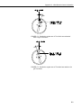
1
INSTRUCTION MANUAL
Met One 034B Wind Set
Revision: 9/14
C o p y r i g h t © 1 9 8 0 - 2 0 1 4
C a m p b e l l S c i e n t i f i c , I n c .
Limited Warranty
“Products manufactured by CSI are warranted by CSI to be free from defects in
materials and workmanship under normal use and service for twelve months
from the date of shipment unless otherwise specified in the corresponding
product manual. (Product manuals are available for review online at
www.campbellsci.com.) Products not manufactured by CSI, but that are resold
by CSI, are warranted only to the limits extended by the original manufacturer.
Batteries, fine-wire thermocouples, desiccant, and other consumables have no
warranty. CSI’s obligation under this warranty is limited to repairing or
replacing (at CSI’s option) defective Products, which shall be the sole and
exclusive remedy under this warranty. The Customer assumes all costs of
removing, reinstalling, and shipping defective Products to CSI. CSI will return
such Products by surface carrier prepaid within the continental United States of
America. To all other locations, CSI will return such Products best way CIP
(port of entry) per Incoterms ® 2010. This warranty shall not apply to any
Products which have been subjected to modification, misuse, neglect, improper
service, accidents of nature, or shipping damage. This warranty is in lieu of all
other warranties, expressed or implied. The warranty for installation services
performed by CSI such as programming to customer specifications, electrical
connections to Products manufactured by CSI, and Product specific training, is
part of CSI's product warranty. CSI EXPRESSLY DISCLAIMS AND
EXCLUDES ANY IMPLIED WARRANTIES OF MERCHANTABILITY
OR FITNESS FOR A PARTICULAR PURPOSE. CSI hereby disclaims,
to the fullest extent allowed by applicable law, any and all warranties and
conditions with respect to the Products, whether express, implied or
statutory, other than those expressly provided herein.”
Assistance
Products may not be returned without prior authorization. The following
contact information is for US and international customers residing in countries
served by Campbell Scientific, Inc. directly. Affiliate companies handle
repairs for customers within their territories. Please visit
www.campbellsci.com to determine which Campbell Scientific company serves
your country.
To obtain a Returned Materials Authorization (RMA), contact CAMPBELL
SCIENTIFIC, INC., phone (435) 227-9000. After an application engineer
determines the nature of the problem, an RMA number will be issued. Please
write this number clearly on the outside of the shipping container. Campbell
Scientific’s shipping address is:
CAMPBELL SCIENTIFIC, INC.
RMA#_____
815 West 1800 North
Logan, Utah 84321-1784
For all returns, the customer must fill out a “Statement of Product Cleanliness
and Decontamination” form and comply with the requirements specified in it.
The form is available from our web site at www.campbellsci.com/repair. A
completed form must be either emailed to [email protected] or faxed to
(435) 227-9106. Campbell Scientific is unable to process any returns until we
receive this form. If the form is not received within three days of product
receipt or is incomplete, the product will be returned to the customer at the
customer’s expense. Campbell Scientific reserves the right to refuse service on
products that were exposed to contaminants that may cause health or safety
concerns for our employees.
Precautions
DANGER — MANY HAZARDS ARE ASSOCIATED WITH INSTALLING, USING, MAINTAINING, AND WORKING ON OR AROUND
TRIPODS, TOWERS, AND ANY ATTACHMENTS TO TRIPODS AND TOWERS SUCH AS SENSORS, CROSSARMS, ENCLOSURES,
ANTENNAS, ETC. FAILURE TO PROPERLY AND COMPLETELY ASSEMBLE, INSTALL, OPERATE, USE, AND MAINTAIN TRIPODS,
TOWERS, AND ATTACHMENTS, AND FAILURE TO HEED WARNINGS, INCREASES THE RISK OF DEATH, ACCIDENT, SERIOUS
INJURY, PROPERTY DAMAGE, AND PRODUCT FAILURE. TAKE ALL REASONABLE PRECAUTIONS TO AVOID THESE HAZARDS.
CHECK WITH YOUR ORGANIZATION'S SAFETY COORDINATOR (OR POLICY) FOR PROCEDURES AND REQUIRED PROTECTIVE
EQUIPMENT PRIOR TO PERFORMING ANY WORK.
Use tripods, towers, and attachments to tripods and towers only for purposes for which they are designed. Do not exceed design
limits. Be familiar and comply with all instructions provided in product manuals. Manuals are available at www.campbellsci.com or
by telephoning (435) 227-9000 (USA). You are responsible for conformance with governing codes and regulations, including safety
regulations, and the integrity and location of structures or land to which towers, tripods, and any attachments are attached. Installation
sites should be evaluated and approved by a qualified engineer. If questions or concerns arise regarding installation, use, or
maintenance of tripods, towers, attachments, or electrical connections, consult with a licensed and qualified engineer or electrician.
General
• Prior to performing site or installation work, obtain required approvals and permits. Comply
with all governing structure-height regulations, such as those of the FAA in the USA.
• Use only qualified personnel for installation, use, and maintenance of tripods and towers, and
any attachments to tripods and towers. The use of licensed and qualified contractors is highly
recommended.
• Read all applicable instructions carefully and understand procedures thoroughly before
beginning work.
• Wear a hardhat and eye protection, and take other appropriate safety precautions while
working on or around tripods and towers.
• Do not climb tripods or towers at any time, and prohibit climbing by other persons. Take
reasonable precautions to secure tripod and tower sites from trespassers.
• Use only manufacturer recommended parts, materials, and tools.
Utility and Electrical
• You can be killed or sustain serious bodily injury if the tripod, tower, or attachments you are
installing, constructing, using, or maintaining, or a tool, stake, or anchor, come in contact with
overhead or underground utility lines.
• Maintain a distance of at least one-and-one-half times structure height, 20 feet, or the distance
required by applicable law, whichever is greater, between overhead utility lines and the
structure (tripod, tower, attachments, or tools).
• Prior to performing site or installation work, inform all utility companies and have all
underground utilities marked.
• Comply with all electrical codes. Electrical equipment and related grounding devices should
be installed by a licensed and qualified electrician.
Elevated Work and Weather
• Exercise extreme caution when performing elevated work.
• Use appropriate equipment and safety practices.
• During installation and maintenance, keep tower and tripod sites clear of un-trained or nonessential personnel. Take precautions to prevent elevated tools and objects from dropping.
• Do not perform any work in inclement weather, including wind, rain, snow, lightning, etc.
Maintenance
• Periodically (at least yearly) check for wear and damage, including corrosion, stress cracks,
frayed cables, loose cable clamps, cable tightness, etc. and take necessary corrective actions.
• Periodically (at least yearly) check electrical ground connections.
WHILE EVERY ATTEMPT IS MADE TO EMBODY THE HIGHEST DEGREE OF SAFETY IN ALL CAMPBELL SCIENTIFIC PRODUCTS,
THE CUSTOMER ASSUMES ALL RISK FROM ANY INJURY RESULTING FROM IMPROPER INSTALLATION, USE, OR
MAINTENANCE OF TRIPODS, TOWERS, OR ATTACHMENTS TO TRIPODS AND TOWERS SUCH AS SENSORS, CROSSARMS,
ENCLOSURES, ANTENNAS, ETC.
Table of Contents
PDF viewers: These page numbers refer to the printed version of this document. Use the
PDF reader bookmarks tab for links to specific sections.
1. Introduction ................................................................. 1
2. Cautionary Statements ............................................... 1
3. Initial Inspection ......................................................... 1
3.1
Ships With List .................................................................................... 2
4. Quickstart .................................................................... 2
4.1
4.2
Step 1—Mount the Sensor ................................................................... 2
Step 2—Use Short Cut to Program Datalogger and Generate
Wiring Diagram ................................................................................ 4
5. Overview ...................................................................... 7
6. Specifications ............................................................. 7
6.1
6.2
6.3
Wind Speed .......................................................................................... 8
Wind Direction..................................................................................... 8
General Specifications ......................................................................... 8
7. Installation ................................................................... 8
7.1
7.2
7.3
7.4
Siting .................................................................................................... 8
Mounting Options ................................................................................ 9
Wiring .................................................................................................. 9
Programming...................................................................................... 10
7.4.1 Wind Speed ................................................................................. 10
7.4.2 Wind Direction ........................................................................... 11
7.4.3 Wind Vector Processing Instruction ........................................... 11
7.4.4 Long Lead Lengths ..................................................................... 12
8. Sensor Maintenance ................................................. 12
9. Troubleshooting........................................................ 12
9.1
9.2
Wind Direction................................................................................... 12
Wind Speed ........................................................................................ 13
10. References ................................................................ 13
Appendices
A. Importing Short Cut Code ...................................... A-1
A.1
Importing Short Cut Code into a Program Editor ........................... A-1
i
Table of Contents
B. Example Program.................................................... B-1
C. Wind Direction Sensor Orientation ....................... C-1
C.1
Determining True North and Sensor Orientation ............................ C-1
D. Wind Direction Measurement Theory.................... D-1
Figures
4-1.
D-1.
034B mounted on a crossarm using a 17953 NU-RAIL crossover
fitting................................................................................................ 3
CM200 Series Crossarm with CM220 Right Angle Mounting
Bracket ............................................................................................. 4
CM216 mount ..................................................................................... 9
Magnetic declination for the contiguous United States (2004) ....... C-2
Declination angles east of True North are subtracted from 0 to
get True North .............................................................................. C-3
Declination angles west of True North are added to 0 to get
True North ................................................................................... C-3
034B potentiometer in a half bridge circuit ..................................... D-1
5-1.
7-1.
7-2.
7-3.
B-1.
Recommended Cable Lengths ............................................................. 7
Connections to Campbell Scientific Dataloggers ................................ 9
Wind Speed Multiplier* .................................................................... 11
Parameters for Wind Direction.......................................................... 11
Wiring for Example Program .......................................................... B-1
4-2.
7-1.
C-1.
C-2.
C-3.
Tables
ii
Met One 034B Wind Set
1.
Introduction
The 034B Wind Set combines a 3-cup anemometer and vane into a single
integrated package to measure wind speed and direction. It is cabled for use
with our dataloggers, and can provide measurements for a variety of
applications.
NOTE
2.
3.
This manual provides information only for CRBasic dataloggers.
It is also compatible with most of our retired Edlog dataloggers.
For Edlog datalogger support, see an older manual at
www.campbellsci.com/old-manuals or contact a Campbell
Scientific application engineer for assistance.
Cautionary Statements
•
READ AND UNDERSTAND the Precautions section at the front of this
manual.
•
The 034B is a precision instrument. Please handle it with care.
•
If the 034B is to be installed at heights over 6 feet, be familiar with tower
safety and follow safe tower climbing procedures.
•
Danger—Use extreme care when working near overhead electrical wires.
Check for overhead wires before mounting the 034B or before raising a
tower.
•
The set screw holes must be covered with labels to prevent corrosion and
assure the warranty.
•
The black outer jacket of the cable is Santoprene® rubber. This
compound was chosen for its resistance to temperature extremes, moisture,
and UV degradation. However, this jacket will support combustion in air.
It is rated as slow burning when tested according to U.L. 94 H.B. and will
pass FMVSS302. Local fire codes may preclude its use inside buildings.
Initial Inspection
Upon receipt of the 034B, inspect the packaging and contents for damage. File
damage claims with the shipping company. Immediately check package
contents against the shipping documentation (see Section 3.1, Ships With List).
Contact Campbell Scientific about any discrepancies.
The model number and cable length are printed on a label at the connection end
of the cable. Check this information against the shipping documents to ensure
the expected product and cable length are received.
1
Met One 034B Wind Set
3.1
Ships With List
The 034B Wind Set ships with:
(1) 1/16-inch Allen wrench
(1) Bushing from Met One
(1) Calibration Sheet
(3) Direction hub stickers
(1) ResourceDVD
(1) Wind Vane
(1) Sensor cable of user-specified length
4.
Quickstart
4.1
Step 1—Mount the Sensor
Tools required:
•
•
•
•
•
•
•
1/2-inch open-end wrench (for CM220)
5/64-inch and 1/16-inch Allen wrenches
compass and declination angle for the site (see Appendix C)
small screw driver provided with datalogger
UV resistant cable ties
small pair of diagonal-cutting pliers
6-inch to 10-inch torpedo level
This quick start installs the 034B using:
•
•
17953, 1 x 1 inch NU-RAIL Crossover Fitting (FIGURE 4-1), or
CM220, Right-Angle Mounting Kit (FIGURE 4-2)
Please review Section 7, Installation, for siting and other guidelines.
CAUTION
2
1.
Fully insert vane arm into hub (see FIGURE 4-1).
2.
Align vane with center axis of sensor (see FIGURE 4-1).
3.
Using the Allen wrench, tighten set screws at the top of the hub (see
FIGURE 4-1).
4.
Cover the set screw hole with one of the small round stickers included
with the 034B. One of these labels is already installed on the hub covering
the set screw that attaches the hub to the sensor. Extra labels are included
with the 034B to recover the holes if the sensor has to be disassembled for
maintenance.
The set screw holes must be covered with the labels to
prevent corrosion and assure the warranty.
5.
Mount a CM200-series crossarm to the tripod or tower.
6.
Orient the crossarm North-South, with the CM220 mount or 17953 NURAIL on the North end. Appendix C contains detailed information on
Met One 034B Wind Set
determining True North using a compass and the magnetic declination for
the site.
7.
Remove the alignment screw at the base of the 034B (FIGURE 4-1).
8.
Insert the 034B into the aluminum bushing provided with the sensor (see
FIGURE 4-1).
9.
Align the hole in the bushing with that in the 034B base and replace the
screw (see FIGURE 4-1).
10. Insert the 034B/bushing into the NU-RAIL fitting (FIGURE 4-1) or the
CM220’s U-bolt (FIGURE 4-2).
11. Align the sensor so that the counter weight points to true South and tighten
the set screws on the NU-RAIL or U-bolts on the CM220. Final sensor
orientation is done after the datalogger has been programmed to measure
wind direction as described in Appendix C.
12. Remove the shoulder screw to allow the vane to rotate (see FIGURE 4-1).
13. Attach the sensor cable to the six pin male connector on the 034B. Make
sure the connector is properly keyed. Finger tighten the knurled ring.
14. Route the sensor cable along the underside of the crossarm to the tripod or
tower, and to the instrument enclosure.
15. Secure the cable to the crossarm and tripod or tower using cable ties.
FIGURE 4-1. 034B mounted on a crossarm using a 17953 NU-RAIL
crossover fitting
3
Met One 034B Wind Set
CM220
CM200 Series Crossarm
FIGURE 4-2. CM200 Series Crossarm with CM220 Right Angle
Mounting Bracket
4.2
Step 2—Use Short Cut to Program Datalogger and
Generate Wiring Diagram
Short Cut is an easy way to program the datalogger to measure the 034B and
assign terminals. The following procedure shows using Short Cut to program
the 034B.
4
1.
Install Short Cut by clicking on the install file icon. Get the install file
from either www.campbellsci.com, the ResourceDVD, or find it in
installations of LoggerNet, PC200W, PC400, or RTDAQ software.
2.
The Short Cut installation should place a Short Cut icon on the
desktop of your computer. To open Short Cut, click on this icon.
Met One 034B Wind Set
3.
When Short Cut opens, select New Program.
4.
Select Datalogger Model and Scan Interval (default of 5 seconds is
OK for most applications). Click Next.
5
Met One 034B Wind Set
5.
Under the Available Sensors and Devices list, select the Sensors |
Meteorological | Wind Speed & Direction folder. Select
034A/034B Wind Speed & Direction Sensor. Click
to move the
selection to the Selected device window. The wind speed defaults to
meters/second. This can be changed by clicking the Wind Speed box
and selecting one of the other options.
6
6.
After selecting the sensor, click at the left of the screen on Wiring
Diagram to see how the sensor is to be wired to the datalogger. The
wiring diagram can be printed out now or after more sensors are
added.
7.
Select any other sensors you have, then finish the remaining Short Cut
steps to complete the program. The remaining steps are outlined in
Short Cut Help, which is accessed by clicking on Help | Contents |
Programming Steps.
Met One 034B Wind Set
5.
8.
If LoggerNet, PC400, RTDAQ, or PC200W is running on your PC,
and the PC to datalogger connection is active, you can click Finish in
Short Cut and you will be prompted to send the program just created
to the datalogger.
9.
If the sensor is connected to the datalogger, as shown in the wiring
diagram in step 6, check the output of the sensor in the datalogger
support software data display to make sure it is making reasonable
measurements.
Overview
The 034B, Wind Set is used to measure horizontal wind speed and direction.
Wind speed is measured with a three cup anemometer. Rotation of the cup
wheel opens and closes a reed switch at a rate proportional to wind speed.
Vane position is transmitted by a 10 kΩ potentiometer. With a precision
excitation voltage applied, the output voltage is proportional to wind direction.
The accompanying Met One manual contains additional information on the
operating principals, installation, and maintenance of the sensor. The Met One
manual is also available at their website (www.metone.com).
Cable length for the 034B is specified when the sensor is ordered. TABLE 5-1
gives the recommended cable length for mounting the sensor at the top of the
tripod/tower with a CM202 crossarm.
TABLE 5-1. Recommended Cable Lengths
CM106
CM110
CM115
CM120
UT10
UT20
UT30
11 ft
14 ft
19 ft
24 ft
14 ft
24 ft
37 ft
The 034B’s cable can terminate in:
•
•
•
6.
Pigtails that connect directly to a Campbell Scientific datalogger
(option –PT).
Connector that attaches to a prewired enclosure (option –PW). Refer
to www.campbellsci.com/prewired-enclosures for more information.
Connector that attaches to a CWS900, Wireless Sensor Interface
(option –CWS). The CWS900 allows the 034B to be used in a
wireless sensor network. Refer to www.campbellsci.com/cws900 for
more information.
Specifications
Features:
• Designed for continuous, long term, unattended operation in adverse
conditions
• Constructed of light-weight aluminum
• Compatible with Campbell Scientific CRBasic dataloggers: CR6,
CR200(X) series, CR800 series, CR1000, CR3000, CR5000, and
CR9000X
7
Met One 034B Wind Set
6.1
6.2
6.3
7.
Wind Speed
Operating Range:
0 to 75 m s–1 (0 to 167 mph)
Threshold:
0.4 m s–1 (0.9 mph)
Accuracy:
±0.12 m s–1 (±0.25 mph) for wind speed
< 10.1 m s–1 (22.7 mph)
±1.1% of reading for wind speeds
> 10.1 m s–1 (22.7 mph)
Output Signal:
contact closure (reed switch)
Resolution:
(1.789 mph) / (scan rate in seconds)
or (0.7998 m s–1) / (scan rate in seconds)
Anemometer Height:
24.4 cm (9.6 in)
Anemometer Radius:
10.7 cm (4.2 in)
Wind Direction
Length:
11.4 cm (4.5 in)
Measurement Range:
0 to 360°
Threshold:
0.4 m s–1 (0.9 mph)
Accuracy:
±4°
Resolution:
0.5°
Potentiometer Resistance:
0 to 10 kΩ open at crossover
General Specifications
Operating Temperature Range:
–30 to +70 °C
Weight:
907 g (2.0 lb)
Installation
If you are programming your datalogger with Short Cut, skip Section 7.3,
Wiring, and Section 7.4, Programming. Short Cut does this work for you. See
Section 4, Quickstart, for a Short Cut tutorial.
7.1
Siting
Locate wind sensors away from obstructions such as trees and buildings. As a
general rule, there should be a horizontal distance of at least ten times the
height of the obstruction between the wind set and the obstruction. If it is
necessary to mount the sensors on the roof of a building, the height of the
sensors, above the roof, should be at least 1.5 times the height of the building.
See Section 10, References, for a list of references that discuss siting wind
speed and direction sensors.
8
Met One 034B Wind Set
7.2
Mounting Options
The 034B can be attached to a CM200-series crossarm via a 17953 NU-RAIL
fitting or a CM220, Right Angle Mounting Bracket. Procedure for using these
mounts is provided in the Quickstart (Section 4.1, Step 1—Mount the Sensor).
Alternatively, the 034B can be attached to the top of a CM106B, CM110,
CM115, or CM120 tripod via the CM216, Sensor Mounting Kit. The CM216
extends 10 cm (4 in) above the mast of the tripod.
FIGURE 7-1. CM216 mount
7.3
Wiring
Connections to Campbell Scientific CRBasic dataloggers are given in TABLE
7-1. To wire an Edlog datalogger, see an older manual at
www.campbellsci.com/old-manuals, or contact a Campbell Scientific
application engineer for assistance.
TABLE 7-1. Connections to Campbell Scientific Dataloggers
Color
Wire Label
CR6
CR9000X
CR800
CR5000
CR3000
CR1000
Red
WS Signal
Pulse
P_SW
Black
WS Signal Ref
Green
WD Signal
SE Analog
SE Analog
Blue
WD Volt Excite
Excitation (VX or EX)
Excitation (VX or EX)
White
WD Signal Ref
Clear
Shield
CR200(X)
9
Met One 034B Wind Set
The dataloggers can also measure wind speed on a control port. With this
option the black wire is connected to the 5 V terminal.
NOTE
7.4
A 034B-L Wind Set purchased directly from Met One Instruments
has a different configuration on the 6-pin connector. In addition,
they do not have the 10 kΩ resistance on the excitation line. The
wiring diagram and the multiplier and offset, for wind direction,
are different than the examples in this document.
Programming
Short Cut is the best source for up-to-date datalogger programming code.
Programming code is needed,
•
•
when creating a program for a new datalogger installation
when adding sensors to an existing datalogger program
If your data acquisition requirements are simple and you are connecting the
sensor to a pulse port, you can probably create and maintain a datalogger
program exclusively with Short Cut. If your data acquisition needs are more
complex, the files that Short Cut creates are a great source for programming
code to start a new program or add to an existing custom program.
NOTE
Short Cut cannot edit programs after they are imported and edited
in CRBasic Editor.
A Short Cut tutorial is available in Section 4.2, Step 2—Use Short Cut to
Program Datalogger and Generate Wiring Diagram. If you wish to import
Short Cut code into CRBasic Editor to create or add to a customized program,
follow the procedure in Appendix A.1, Importing Short Cut Code into a
Program Editor. Programming basics for CRBasic dataloggers are provided in
the following sections. Complete program examples for select CRBasic
dataloggers can be found in Appendix B, Example Program. Programming
basics and programming examples for Edlog dataloggers are provided at
www.campbellsci.com/old-manuals.
7.4.1 Wind Speed
Wind speed is measured with the Pulse Count instruction, using the Switch
Closure configuration and set to output frequency in Hertz (see Appendix B,
Example Program, for examples).
10
Met One 034B Wind Set
The expression for wind speed (U) is:
U = MX + B
where
M = multiplier
X = number of pulses per second (Hertz)
B = offset
TABLE 7-2 lists the multipliers (M) and offsets (Off) to obtain meters/second
or miles/hour when the Pulse Count instruction is configured to output the
result in Hz.
TABLE 7-2. Wind Speed Multiplier*
Model
Meters/Second
Miles/Hour
034B
M = 0.7989
Off = 0.28
M = 1.787
Off = 0.63
*When configured to output counts, the multiplier above is divided
by the execution interval in seconds.
7.4.2 Wind Direction
The CR200(X) dataloggers use the ExDelSE() instruction to measure wind
direction. All other CRBasic dataloggers use the BRHalf() instruction (see
Appendix B, Example Program, for example).
Excitation voltages, range codes, and multipliers for our dataloggers are listed
in TABLE 7-3. The multiplier value converts the sensor’s millivolt output to
degrees. Appendix D has additional information on the measurement
instructions.
TABLE 7-3. Parameters for Wind Direction
CR800
CR1000
CR5000
CR3000
Measurement
Range, Integration
2500 mV, 60 Hz,
reverse excitation
5000 mV, 60 Hz,
reverse excitation
N/A
Excitation Voltage
2500 mV
5000 mV
2500 mV
Multiplier
720
720
0.288
Offset
0
0
0
CR200(X)
7.4.3 Wind Vector Processing Instruction
The Wind Vector output instruction is used to process and store mean wind
speed, unit vector mean wind direction, and standard deviation of the wind
direction (optional) from the measured wind speed and direction values.
11
Met One 034B Wind Set
7.4.4 Long Lead Lengths
When sensor lead length exceeds 100 feet, the settling time allowed for the
measurement of the vane should be increased to 20 milliseconds.
For dataloggers programmed with CRBasic, increase the Settling Time
parameter of the CRBasic instruction to 20 milliseconds (20,000
microseconds).
8.
Sensor Maintenance
Monthly
•
Do a visual/audio inspection of the anemometer at low wind speeds.
Verify that the cup assembly and wind vane rotate freely. Inspect the
sensor for physical damage. Verify cups and vane are tight.
6 Months
•
Replace anemometer bearings if operating under harsh conditions.
Annually
•
Replace anemometer bearings. Refer to the Assistance page at the
beginning of this document for the procedure of returning the sensor to
Campbell Scientific for bearing replacement.
2 Years
•
9.
Replace the wind vane potentiometer and bearings. Refer to the
Assistance page at the beginning of this document for the procedure of
returning the sensor to Campbell Scientific for wind vane and bearing
replacement.
Troubleshooting
9.1
Wind Direction
Symptom: NAN, –9999, or no change in direction
12
1.
Check that the sensor is wired to the excitation and single-ended channel
specified by the measurement instruction.
2.
Verify that the excitation voltage and range code are correct for the
datalogger type.
3.
Disconnect the sensor from the datalogger and use an ohm meter to check
the potentiometer. Resistance should vary from 11 to 21 kohms between
the blue and green wires depending on vane position. Resistance should
vary from 1 to 11 kohms between the white and green wires depending on
vane position.
Met One 034B Wind Set
Symptom: Incorrect wind direction
9.2
1.
Verify that the excitation voltage, range code, multiplier and offset
parameters are correct for the datalogger type.
2.
Check orientation of sensor as described in Section 7, Installation.
Wind Speed
Symptom: No wind speed
1.
Check that the sensor is wired to the pulse channel specified by the pulse
count instruction.
2.
Disconnect the sensor from the datalogger and use an ohm meter to check
the reed switch. The resistance between the red and black wires should
vary from infinite (switch open) to less than 1 ohm (switch closed) as the
cupwheel is slowly turned.
3.
Verify that the configuration code (switch closure, Hertz), and multiplier
and offset parameters for the pulse count instruction are correct for the
datalogger type.
10. References
The following references give detailed information on siting wind speed and
wind direction sensors.
EPA, 1989: Quality Assurance Handbook for Air Pollution Measurements
System, Office of Research and Development, Research Triangle Park, NC,
27711.
EPA, 1987: On-Site Meteorological Program Guidance for Regulatory
Modeling Applications, EPA-450/4-87-013, Office of Air Quality Planning and
Standards, Research Triangle Park, NC 27711.
The State Climatologist, 1985: Publication of the American Association of
State Climatologists: Height and Exposure Standards, for Sensors on
Automated Weather Stations, vol. 9, No. 4.
WMO, 1983: Guide to Meteorological Instruments and Methods of
Observation, World Meteorological Organization, No. 8, 5th edition, Geneva,
Switzerland.
13
Met One 034B Wind Set
14
Appendix A. Importing Short Cut Code
This tutorial shows:
•
•
How to import a Short Cut program into a program editor for
additional refinement
How to import a wiring diagram from Short Cut into the comments of
a custom program
A.1 Importing Short Cut Code into a Program Editor
Short Cut creates files that can be imported into CRBasic Editor program
editor. These files normally reside in the C:\campbellsci\SCWin folder and
have the following extensions:
•
•
•
•
•
•
•
.DEF (wiring and memory usage information)
.CR6 (CR6 datalogger code)
.CR2 (CR200(X) datalogger code)
.CR1 (CR1000 datalogger code)
.CR8 (CR800 datalogger code)
.CR3 (CR3000 datalogger code)
.CR9 (CR9000(X) datalogger code)
Use the following procedure to import Short Cut code into CRBasic Editor
(CR200(X), CR1000, CR800, CR3000, CR5000 CR9000(X) dataloggers).
NOTE
1.
Create the Short Cut program following the procedure in Section 4,
Quickstart. Finish the program and exit Short Cut. Make note of the file
name used when saving the Short Cut program.
2.
Open CRBasic Editor.
3.
Click File | Open. Assuming the default paths were used when Short Cut
was installed, navigate to C:\CampbellSci\SCWin folder. The file of
interest has a “.CR6,” “.CR2”, “.CR1”, “.CR8”, “.CR3”, “.CR9”, or
“.CR5” extension, for CR6, CR200(X), CR1000, CR800, CR3000,
CR9000(X), or CR5000 dataloggers, respectively. Select the file and click
Open.
4.
Immediately save the file in a folder different from \Campbellsci\SCWin,
or save the file with a different file name.
Once the file is edited with CRBasic Editor, Short Cut can no
longer be used to edit the datalogger program. Change the name
of the program file or move it, or Short Cut may overwrite it next
time it is used.
5.
The program can now be edited, saved, and sent to the datalogger.
6.
Import wiring information to the program by opening the associated .DEF
file. Copy and paste the section beginning with heading “-Wiring for
CRXXX–” into the CRBasic program, usually at the head of the file.
A-1
Appendix A. Importing Short Cut Code
After pasting, edit the information such that a ' character (single quotation
mark) begins each line. This character instructs the datalogger compiler to
ignore the line when compiling the datalogger code.
A-2
Appendix B. Example Program
The following CR1000 program measures the 034B every 5 seconds, and store
mean wind speed, unit vector mean direction, and standard deviation of the
direction every 60 minutes. Wiring for the examples is given in TABLE B-1.
TABLE B-1. Wiring for Example Program
Color
Description
CR1000
Red
Wind Spd. Signal
P1
Black
Wind Spd. Reference
Green
Wind Dir. Signal
SE 1
Blue
Wind Dir. Excitation
EX 1
White
Wind Dir. Reference
Clear
Wind Dir. Shield
'CR1000
'Declare Variables and Units
Public Batt_Volt
Public WS_ms
Public WindDir
Units Batt_Volt=Volts
Units WS_ms=meters/second
Units WindDir=degrees
'Define Data Tables
DataTable(Table1,True,-1)
DataInterval(0,60,Min,10)
WindVector (1,WS_ms,WindDir,FP2,False,0,0,0)
FieldNames("WS_ms_Avg,WindDir_Avg,WindDir_StDev")
EndTable
'Main Program
BeginProg
Scan(5,Sec,1,0)
'Default Datalogger Battery Voltage measurement Batt_Volt:
Battery(Batt_Volt)
'034A/034B Wind Speed & Direction Sensor measurements WS_ms and WindDir:
PulseCount(WS_ms,1,1,2,1,0.7989,0.28)
If WS_ms=0.2811 Then WS_ms=0
BrHalf(WindDir,1,mV2500,1,1,1,2500,True,0,_60Hz,720.0,0)
If WindDir>=360 OR WindDir < 0 Then WindDir=0
'Call Data Tables and Store Data
CallTable(Table1)
NextScan
EndProg
'Use 5000 mV
'excitation for
'the CR3000 and
'CR5000 dataloggers
B-1
Appendix B. Example Program
B-2
Appendix C. Wind Direction Sensor
Orientation
C.1 Determining True North and Sensor Orientation
Orientation of the wind direction sensor is done after the datalogger has been
programmed, and the location of True North has been determined. True North
is usually found by reading a magnetic compass and applying the correction for
magnetic declination; where magnetic declination is the number of degrees
between True North and Magnetic North. The preferred method to obtain the
magnetic declination for a specific site is to use a computer service offered by
NOAA at www.ngdc.noaa.gov/geomag. Magnetic declination can also be
obtained from a map or local airport. A general map showing magnetic
declination for the contiguous United States is shown in FIGURE C-1.
Declination angles east of True North are considered negative, and are
subtracted from 360 degrees to get True North as shown FIGURE C-2 (0° and
360° are the same point on a compass). For example, the declination for
Logan, Utah is 14° East. True North is 360° – 14°, or 346° as read on a
compass. Declination angles west of True North are considered positive, and
are added to 0 degrees to get True North as shown in FIGURE C-3.
Orientation is most easily done with two people, one to aim and adjust the
sensor, while the other observes the wind direction displayed by the datalogger.
1.
Establish a reference point on the horizon for True North.
2.
Sighting down the instrument center line, aim the nose cone, or
counterweight at True North. Display the input location or variable for
wind direction using a hand-held keyboard display, PC, or laptop.
3.
Loosen the U-bolt on the CM220 or the set screws on the NU-RAIL that
secure the base of the sensor to the crossarm. While holding the vane
position, slowly rotate the sensor base until the datalogger indicates 0
degrees. Tighten the set screws.
C-1
Appendix C. Wind Direction Sensor Orientation
FIGURE C-1. Magnetic declination for the contiguous United States
(2004)
C-2
Appendix C. Wind Direction Sensor Orientation
FIGURE C-2. Declination angles east of True North are subtracted
from 0 to get True North
FIGURE C-3. Declination angles west of True North are added to 0 to
get True North
C-3
Appendix C. Wind Direction Sensor Orientation
C-4
Appendix D. Wind Direction
Measurement Theory
It is not necessary to understand the concepts in this section for the general
operation of the 034B, Wind Set with a Campbell Scientific datalogger.
A 034B purchased from Campbell Scientific has a 9.53 kΩ fixed resistor and a
variable resistor on the excitation line. The variable resistor is adjusted by the
manufacturer so its resistance plus the 9.53 kΩ resistor equals the resistance of
the potentiometer (Rf = Rs + Rt).
FIGURE D-1. 034B potentiometer in a half bridge circuit
The vanes are calibrated due south and then the potentiometer is adjusted until
each half of the potentiometer has equal resistance.
D-1
Appendix D. Wind Direction Measurement Theory
D-2
Campbell Scientific Companies
Campbell Scientific, Inc. (CSI)
815 West 1800 North
Logan, Utah 84321
UNITED STATES
www.campbellsci.com • [email protected]
Campbell Scientific Centro Caribe S.A. (CSCC)
300 N Cementerio, Edificio Breller
Santo Domingo, Heredia 40305
COSTA RICA
www.campbellsci.cc • [email protected]
Campbell Scientific Africa Pty. Ltd. (CSAf)
PO Box 2450
Somerset West 7129
SOUTH AFRICA
www.csafrica.co.za • [email protected]
Campbell Scientific Ltd. (CSL)
Campbell Park
80 Hathern Road
Shepshed, Loughborough LE12 9GX
UNITED KINGDOM
www.campbellsci.co.uk • [email protected]
Campbell Scientific Australia Pty. Ltd. (CSA)
PO Box 8108
Garbutt Post Shop QLD 4814
AUSTRALIA
www.campbellsci.com.au • [email protected]
Campbell Scientific Ltd. (CSL France)
3 Avenue de la Division Leclerc
92160 ANTONY
FRANCE
www.campbellsci.fr • [email protected]
Campbell Scientific (Beijing) Co., Ltd.
8B16, Floor 8 Tower B, Hanwei Plaza
7 Guanghua Road
Chaoyang, Beijing 100004
P.R. CHINA
www.campbellsci.com • [email protected]
Campbell Scientific Ltd. (CSL Germany)
Fahrenheitstraße 13
28359 Bremen
GERMANY
www.campbellsci.de • [email protected]
Campbell Scientific do Brasil Ltda. (CSB)
Rua Apinagés, nbr. 2018 ─ Perdizes
CEP: 01258-00 ─ São Paulo ─ SP
BRASIL
www.campbellsci.com.br • [email protected]
Campbell Scientific Spain, S. L. (CSL Spain)
Avda. Pompeu Fabra 7-9, local 1
08024 Barcelona
SPAIN
www.campbellsci.es • [email protected]
Campbell Scientific Canada Corp. (CSC)
14532 – 131 Avenue NW
Edmonton AB T5L 4X4
CANADA
www.campbellsci.ca • [email protected]
Please visit www.campbellsci.com to obtain contact information for your local US or international representative.