1
CEILING CASSETTE
SPLIT TYPE AIR CONDITIONERS
(B-Series)
INSTALLATION MANUAL
IM-CKB-0501
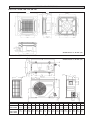
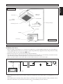
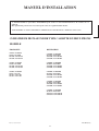
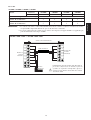
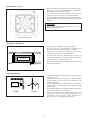
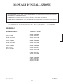
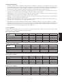
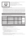
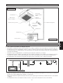
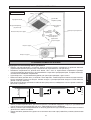
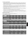
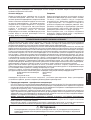
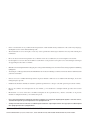
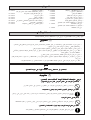
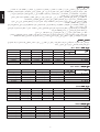
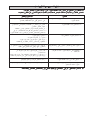
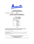
OUTLINE AND DIMENSIONS
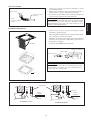
Indoor Unit : CK15B / 20B / 25B / 30B / BR
727,0 (28,6)
362,0 (14,3)
340,0 (13,4)
600,0 (23,6)
582,0 (22,9)
573,0 (22,6)
240,0 (9,4)
650,0 (25,6)
192,0 (7,6)
489,0 (19,3)
727,0 (28,6)
22,0 (0,9)
80,0 (3,1)
130,0 (5,1)
489,0 (19,3)
68,0
(2,7)
532,0 (20,9)
146,0
(5,7)
120,0 (4,7)
49,0
(1,9)
293,0 (11,5)
409,0 (16,1)
605,0 (23,8)
All dimensions are in mm / (in)
All dimensions are in mm / (in)
A
39 (1,5)
M
5 (0,2)
15 (0,6)
C
N
R
15 (0,6)
39 (1,5)
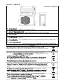
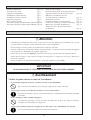
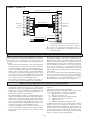
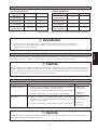
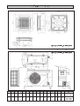
Outdoor Unit : (SL - B Series)
Q
P
5 (0,2)
P
840 (33,1)
C
160 (6,3) H
Dimension
A
B
C
D
E
F
G
H
J
K
20 (0,8)
20 (0,8)
20 (0,8)
(2,6)
65 J
K
E
F
B
141
(5,6)
2,5 (0,1)
G
D
L
L
M
N
P
Q
R
10B / 10BR
15B / 15BR
740
494 270 266
(29,1) (19,4) (10,6) (10,5)
233 474
47
(9,2) (18,7) (1,9)
55
(2,2)
65
(2,6)
166
(6,5)
92
348 318
(3,6) (13,7) (12,5)
20B / 20BR
25B / 25BR
30B / 30BR
840
646 330 297
309 626
41
(33,1) (25,4) (13,0) (11,7) (12,2) (24,6) (1,6)
85
(3,3)
75
(3,0)
177
(7,0)
106 408 378
124 592 78,5
(4,2) (16,1) (14,9) (4,9) (23,3) (3,1)
i
129 482 68,5
(5,1) (19,0) (2,7)
141,5
(5,6)
746,5 (29,4)
20,0
(0,8) 448,0 (17,6)
141,5
(5,6)
20,0
(0,8)
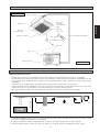
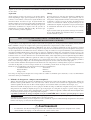
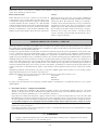
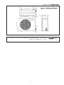
Outdoor Unit : SL30C & CR
850,0 (33,5)
1030,0 (40,6)
All dimensions are in mm / (in)
40,0
(1,6)
400,0 (15,7)
40,0
(1,6)
320,0 (12,6)
25,0 (1,0)
50,0
(2,0)
85,0 (3,3)
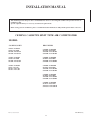
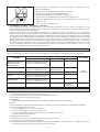
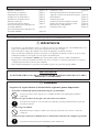
! Caution from being in contact with these places.
Les bords coupants et les surfaces du refroidisseur tuulaire présentent un risque
! Avertissement de blessure. Mieux vaut éviter le contact avec ces endroits.
Scharfe Kanten und Wärmetauscherflächen stellen eine Gefahrenquelle dar. Jeglicher
! Vorsicht Kontakt mit diesen Stellen ist zu vermeiden.
Per preservarsi da eventuali ferite, evitare di toccare gli spigoli afilati e la superficie dei
! Cautela serpentini.
! Cuidado Los Bordes afilados y la superficie del serpentín pueden producir lesiones. Evite tocarlos.
края и поверхности змеевиков являются потенциальными
! Осторожно Острые
местами нанесения травм. Остерегайтесь контакта с этими местами.
Sharp edges and coil surfaces are potential locations which may cause injury hazards. Avoid
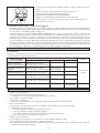
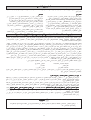
NOTICE
This product is subjected to Waste of Electrical and Electronic Equipment Regulations (WEEE
Regulations). The waste product shall be separately collected by specific collection and treatment centre.
Please refer to local authorithy for these centres. This is only applicable to European Union countries.
Ce produit est soumis à la réglementation concernant les déchets des équipements électriques et
électroniques (ré
r
é
ê
é séparé
r ment par un centre de collecte
é
é
ître ces centres. Ceci
éenne.
Gerää
ä
ätes
getrennt vom Hausmüll bei Ihrer örtlichen Mülldeponie bzw. Ihrem örtlichen
äändiges Abfall-Amt. Dieser
Hinweis gilt nur fü
f r Länder
ä
der Europäischen Union.
Questo prodotto è soggetto alle disposizioni RAEE (Rifiuti di apparecchiature elettriche ed elettroniche).
à
à locali. Questa disposizione è valida solamente i paesi
dell’U.E.
ñ
éctrico y Electrónico en materia de
í
ífico
á
de colecció
solamente aplicable a los países de la Unión Europea.
отходов
.
правила
правилами по утилизации
(WEEE Regulations).
и
,
. Эти
Европейского
.
ii
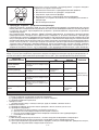
English
INSTALLATION MANUAL
This manual provides the procedures of installation to ensure a safe and good standard of operation for the air
conditioner unit.
Special adjustment may be necessary to suit local requirements.
Before using your air conditioner, please read this instruction manual carefully and keep it for future reference.
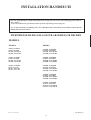
CEILING CASSETTE SPLIT TYPE AIR CONDITIONER
MODEL
COOLING ONLY
HEAT PUMP
CK25B / YCK025B
SL25B / YLC025B
4SL25B / Y4LC025B
5SL25B / Y5LC025B
CK15BR / YCK015BR
SL15BR / YLC015BR
4SL15BR / Y4LC015BR
5SL15BR / Y5LC015BR
CK30B / YCK030B
SL30B / YLC030B
4SL30B / Y4LC030B
5SL30B / Y5LC030B
CK20BR / YCK020BR
SL20BR / YLC020BR
4SL20BR / Y4LC020BR
5SL20BR / Y5LC020BR
CK30B / YCK030B
SL30C / YLC30C
4SL30C / Y4LC30C
5SL30C / Y5LC30C
CK25BR / YCK025BR
SL25BR / YLC025BR
4SL25BR / Y4LC025BR
5SL25BR / Y5LC025BR
CK30BR / YCK030BR
SL30BR / YLC030BR
4SL30BR / Y4LC030BR
5SL30BR / Y5LC030BR
CK30BR / YCK030BR
SL30CR / YLC030CR
4SL30CR / Y4LC030CR
5SL30CR / Y5LC030CR
IM-CKB-0501 (2)
Part No.: A08019013026
1-1
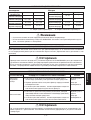
CONTENTS
- Outline And Dimensions
- Safety Precautions
- Installation Diagram
- Installation of Indoor Unit
- Installation of Outdoor Unit
- Refrigerant Piping Work
- Electrical Wiring Connection
- Special Precautions When Dealing With R410A Unit
- Special Precautions When Dealing With R407C Unit
- Vacuuming and Charging
- Special Precautions When Charging Unit With
Copeland Scroll Compressors
- Indicator Lights
- Overall Checking
- Standard Operation Conditions
- Auto Random Re-start Function
- Service and Maintenance
- Troubleshooting
page i – ii
page 2
page 3
page 3
page 6
page 6
page 8
page 10
page 10
page 11
page 11
page 12
page 12
page 13
page 13
page 13
page 14
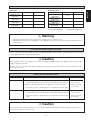
SAFETY PRECAUTIONS
Before installing the air conditioner unit, please read the following safety precautions carefully.
! Warning
•
Installation and maintenance should be performed by qualified persons who are familiar with local code and
regulation, and experienced with this type of appliance.
•
All field wiring must be installed in accordance with the national wiring regulation.
•
Ensure that the rated voltage of the unit corresponds to that of the name plate before commencing wiring work
according to the wiring diagram.
•
The unit must be GROUNDED to prevent possible hazard due to insulation failure.
•
All electrical wiring must not touch the refrigerant piping or any moving parts of the fan motors.
•
Confirm that the unit has been switched OFF before installing or servicing the unit.
IMPORTANT
DO NOT INSTALL OR USE THE AIR CONDITIONER UNIT IN A LAUNDRY ROOM.
! Caution
Please take note of the following important points when installing.
• Do not install the unit where leakage of flammable gas may occur.
If gas leaks and accumulates around the unit, it may cause fire ignition.
• Ensure that the drainage piping is connected properly.
If the drainage piping is not connected properly, it may cause water leakage which will dampen the
furniture.
• Do not overcharge the unit.
This unit is factory pre-charged. Overcharge will cause over-current or damage to the compressor.
• Ensure that the units panel is closed after service or installation.
Unsecured panels will cause the unit to operate noisily.
1-2
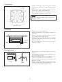
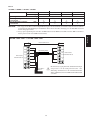
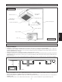
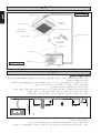
INSTALLATION DIAGRAM
English
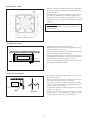
Indoor Unit
Drain Hose
IR Receiver
LED Light
Front Panel
Air Intake Grille
Air Filter
(behind the grille)
Refrigerant Piping
Air Discharge Louver
Wireless
Remote Control
or
Wired Remote Control
Air Intake
Air Intake
Air Discharge
Outdoor Unit
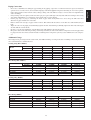
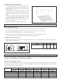
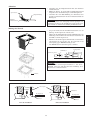
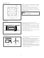
INSTALLATION OF INDOOR UNIT
Preliminary Site Survey
Min. 0.5 m
Min. 0.5 m
Min. 0.5 m
Max. 0.3 m
Min. 1.0 m
•
Beam
•
•
Electrical supply and installation is to conform to local authority's (e.g. National Electrical Board) codes and regulations.
Voltage supply fluctuation must not exceed +10% of rated voltage. Electricity supply lines must be independent of welding
transformers which can cause high supply fluctuation.
Ensure that the location is convenient for wiring, piping and drainage.
The indoor unit must be installed in such that is free from any obstacles in path of cool air discharge and warm air return,
and must allow spreading of air throughout the room (near the center of the room).
Must be provide clearance for the indoor unit from the wall and obstacles as shown in the figure.
Max. 3.0 m
•
•
Obstacle
Floor
•
•
•
The installation place must be strong enough to support a load 4 times the indoor unit weight to avoid amplifying noise and
vibration.
The installation place (handing ceiling surface) must be assuring levelness and the height in the ceiling is 350 mm or more.
The indoor unit must be away from heat and steam sources (avoid installing it near an entrance).
1-3
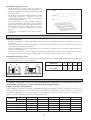
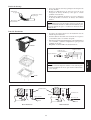
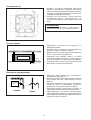
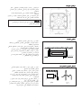
Unit Installation
•
•
•
Measure and mark the position for the hanging rod. Drill
the hole for the angle nut on the ceiling and fix the hanging
rod.
The dimensions of the installation template are the same
as those of the ceiling opening dimensions.
Before ceiling laminating work is completed, be sure to
fit the installation template to the indoor unit.
NOTE
Be sure to discuss the ceiling drilling work with the
installers concerned.
Ceiling board opening
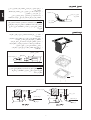
Unit Hanging
•
•
•
•
Indoor Unit
Ceiling
Board
•
Confirm the pitch of the hanging rod.
Hold the unit and hang it on the hanging rod with the nut
and washer.
Adjust the unit height to 35.0 mm between the indoor unit
bottom surface and the ceiling surface.
Confirm with a level gauge that the unit is installed
horizontally and tighten the nut and bolt to prevent unit
falling and vibration.
Open the ceiling board along the outer edge of the paper
installation template.
35.0 mm
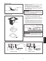
Drain Piping Work
•
•
•
Indoor Unit
•
Pipe Clamp
Good
Bad
•
1-4
Drain pipe must be in downward gradient for smooth
drainage.
Avoid installing the drain pipe in up and down slope to
prevent reversed water flow.
During the drain pipe connection, be careful not to exert
extra force on the drain connector at indoor unit.
The outside diameter of the drain connection at the flexible
drain hose is 20 mm.
Be sure to execute heat insulation (polyethylene foam with
thickness more than 8.0 mm) on the drain piping to avoid
the condensed water dripping inside the room.
•
•
Feed Water
•
Main Drain Pipe
Connect the main drain pipe to the flexible drain hose.
Feed water from flexible drain hose to check the piping
for leakage.
When the test is completed, connect the flexible drain hose
to the drain connector on the indoor unit.
NOTE
This indoor unit uses a drain pump for condensed water
drainage. Install the unit horizontally to prevent water
leakage or condensation around the air outlet.
Flexible
Drain Hose
Panel Installation
•
•
•
OPEN
•
Be sure to remove the installation template before installing
the front panel.
Open the air intake grille by pull back the catchers and
remove it together with filter from panel.
Install the front frame panel onto the indoor unit by 4
screws and tighten it completely to prevent cool air
leakage.
Connect the LED wire to the indoor unit.
Control Box
LED Wire
From Front Panel
NOTE
Install the front frame panel firmly to prevent cool air
leakage which will cause condensation and water dripping.
Screw
Indoor unit
cool
air
cool
air
air leak
air leak
ceiling board
ceiling board
Panel
Panel
Bad Installation
Good Installation
1-5
English
Drain Test
Air intake grille installation
•
•
•
•
•
•
Before installing the air intake grille, be sure to fix the
ionizer filter to the air filter.
Install the air intake grille together with the air filter to the
front panel.
The grille can be fit in any direction, when selecting
direction, the ceiling design and grille operability should
be considered.
If the unit comes with ionizer filter (optional item), make
sure to fix the ionizer filter to the air filter before installing
the air intake grille.
Fix the ionizer filter to the air filter with the black side on
top and white side at bottom.
Carefully clip on the ionizer filter frame.
Frame
Ionizer
Filter
INSTALLATION OF OUTDOOR UNIT
Preliminary site survey
•
•
•
•
•
A place protected from rain, direct sunlight and well-ventilated wherever practicable.
A place capable of bearing the weight of the outdoor unit and isolating noise and vibration.
A place where there are no obstruction of air flow into or out the unit.
Do not put any object which may become obstacle for the air flow into or out the outdoor unit.
The location must not be susceptible to high concentration dust, oil, salt or sulfide gas.
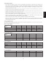
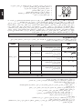
Outdoor unit installation
•
Install the outdoor unit firmly and horizontally. Maintain a space clearance from the obstruction as shown in below for
servicing and air ventilation.
A
B
C
D
SL Series
A
B
C
D
Min. Distance, mm (in)
300
1000
300
500
(11.8) (39.4) (11.8) (19.7)
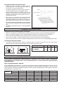
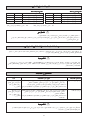
REFRIGERANT PIPING WORK
Refrigerant piping is important in particular. Refrigeration cycle of the split air conditioner is realized
by the perfect piping work.
Piping length and elevation
If the piping is too long, both the capacity and reliability of unit will drop. As the number of bends increase, resistance to
flow of refrigerant system increases, thus lowering cooling capacity and as a result the compressor may become defective.
Always choose the shortest path and follow the recommendation as tabulated below.
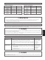
Model
Indoor
Outdoor
Max. length, m (ft)
Max. elevation, m (ft)
Max. no. of bends
Liquid pipe size
Gas pipe size
CK15B/BR
CK20B/BR
CK25B/BR
CK30B/BR
CK30B/BR
SL15B/BR
12 (39)
5 (16)
10
1/4”
1/2”
SL20B/BR
15 (49)
8 (26)
10
1/4”
5/8”
SL25B/BR
15 (49)
8 (26)
10
3/8”
5/8”
SL30B
35 (114)
8 (26)
10
3/8”
5/8”
SL30C/CR
35 (114)
15 (49)
10
3/8”
5/8”
1-6
•
•
•
•
•
•
•
Do not use contaminated or damaged copper tubing. If any piping, evaporator or condenser had been exposed or had been
opened for 15 seconds or more, then vacuum and purge with field supplied refrigerant. Generally, do not remove plastic,
rubber plugs and brass nuts from the valves, fittings, tubing and coils until it is ready to connect suction or liquid line into
valves or fittings.
If any brazing work is required, ensure that nitrogen gas is passed through coil and joints while the brazing work is being
done. This will eliminate soot formation on the inside wall of copper tubings.
Cut the pipe stages by stages, advancing the blade of pipe cutter slowly. Extra force and a deep cut will cause more
distortion of pipe and therefore extra burr.
Remove burrs from cut edges of pipes with a remover. This will avoid unevenness on the flare face which will cause gas
leak.
Align the center of the piping and sufficiently tighten the flare nut with fingers. Finally, tighten the flare nut with torque
wrench until the wrench clicks.
Be sure to execute heat insulation. (polyurethane form with thickness more than 15 mm)
Except the outdoor unit which is pre-charge with refrigerant R22, the indoor unit and the refrigerant connection pipes must
be purged because the air that contain moisture remaining in the refrigerant cycle may cause malfunction to the compressor.
Additional Charge
The refrigerant is pre-charged in the outdoor unit, but additional charge of refrigerant after vacuuming is necessary. Follow
the recommendation as tabulated below.
Cooling Only (R22 / R407C)
Model
Indoor
Outdoor
L <= 5 m
L=7m
L = 10 m
L = 15 m
L = 20 m
CK15B
SL15B
0.250 kg
0.300 kg
0.325 kg
0.400 kg
–
CK20B
SL20B
0.250 kg
0.280 kg
0.325 kg
0.400 kg
–
CK25B
SL25B
0.100 kg
0.176 kg
0.290 kg
0.480 kg
–
CK30B
SL30B
0.100 kg
0.200 kg
0.350 kg
0.600 kg
0.850 kg
CK30B
SL30C
0.400 kg
0.600 kg
0.650 kg
0.900 kg
1.150 kg
Heat Pump (R22 / R407C)
Model
L <= 5 m
L=7m
L = 10 m
L = 15 m
L = 20 m
Indoor
Outdoor
CK15B
SL15BR
–
0.050 kg
0.075 kg
0.150 kg
–
CK20BR
SL20BR
–
0.050 kg
0.075 kg
0.150 kg
–
CK25BR
SL25BR
–
0.100 kg
0.500 kg
0.750 kg
–
CK30BR
SL30CR
–
0.100 kg
0.250 kg
0.500 kg
0.750 kg
Cooling Only (R410A)
Model
L <= 5 m
L=7m
L = 10 m
L = 15 m
L = 20 m
CK15B
0.225 kg
0.270 kg
0.293 kg
0.360 kg
–
CK20B
0.225 kg
0.252 kg
0.293 kg
0.360 kg
–
CK25B
0.090 kg
0.159 kg
0.261 kg
0.432 kg
–
CK30B
0.090 kg
0.180 kg
0.315 kg
0.541 kg
0.766 kg
CK30B
0.360 kg
0.541 kg
0.586 kg
0.811 kg
1.036 kg
Heat Pump (R410A)
Model
L <= 5 m
L=7m
L = 10 m
L = 15 m
L = 20 m
CK15BR
–
0.045 kg
0.068 kg
0.135 kg
–
CK20BR
–
0.045 kg
0.068 kg
0.135 kg
–
1-7
CK25BR
–
0.090 kg
0.450 kg
0.676 kg
–
CK30BR
–
0.090 kg
0.225 kg
0.450 kg
0.676 kg
English
Piping Connection
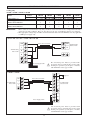
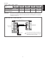
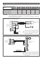
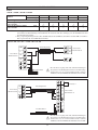
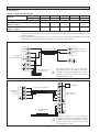
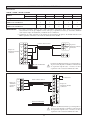
ELECTRICAL WIRING CONNECTION
Cooling Only
CK15B / CK20B / CK25B & CK30B
Indoor
Outdoor
Model
Voltage Range **
Power Supply Cable Size *
Number Of Conductors
Interconnection Cable Size *
Number Of Conductors
IMPORTANT:
mm2
mm2
CK15B
CK20B
CK25B
CK30B
CK30B
SL15B
SL20B
SL25B
SL30B
SL30C
220 – 240V /1Ph /50Hz + ! or 208 – 230V /1Ph /60Hz + !
1.5
2.5
2.5
4.0
4.0
3
3
3
3
3
1.5
2.5
2.5
2.5
2.5
3
3
3
3
4
* These values are for information only. They should be checked and selected to comply with local and/or
national codes and regulations. They are also subject to the type of installation and size of conductors.
** The appropriate voltage range should be checked with label data on the unit. ETL listed is only applicable
to 60Hz power supply only.
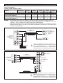
CK15B / 20B / 25B / 30B <> SL15B / 20B / 25B / 30B
COMP
Interconnection Cable
COMP Terminal Strip
Outdoor Unit
L
Terminal Strip
Indoor Unit
N
N
N
Power Supply Cable
!
The electrical power must be provided with
protection devices (circuit breaker or fuse) with
double pole separation system (phase + neutral)
with minimum contact gap of 3mm.
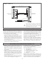
CK30B <> SL30C
S
Capacitor
COMP
R
Interconnection Cable
COMP
Terminal Strip
Indoor Unit
L
L
N
Terminal Strip
Outdoor Unit
N
L
N
Power Supply Cable
!
1-8
The electrical power must be provided with
protection devices (circuit breaker or fuse) with
double pole separation system (phase + neutral)
with minimum contact gap of 3mm.
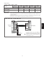
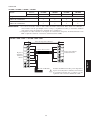
Heat Pump
Model
Indoor
Outdoor
Voltage Range **
Power Supply Cable Size *
Number Of Conductors
Interconnection Cable Size *
Number Of Conductors
IMPORTANT:
mm2
mm2
CK15BR
CK20BR
CK25BR
CK30BR
SL15BR
SL20BR
SL25BR
SL30CR
220 – 240V /1Ph /50Hz + ! or 208 – 230V /1Ph /60Hz + !
1.5
2.5
2.5
4.0
3
3
3
3
1.5
2.5
2.5
2.5
5
5
5
6
* These values are for information only. They should be checked and selected to comply with local and/or
national codes and regulations. They are also subject to the type of installation and size of conductors.
** The appropriate voltage range should be checked with label data on the unit. ETL listed is only applicable
to 60Hz power supply only.
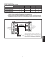
CK15BR / 20BR / 25BR <> SL15BR / 20BR / 25BR
Outdoor Coil Sensor
4WV
OF
4WV
OF
Interconnection Cable
COMP
Terminal Strip
Indoor Unit
COMP
Terminal Strip
Outdoor Unit
L
N1
N
N2
Power Supply
Cable
1-9
!
The electrical power must be provided with
protection devices (circuit breaker or fuse) with
double pole separation system (phase + neutral)
with minimum contact gap of 3mm.
English
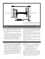
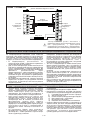
CK15BR / CK20BR / CK25BR / CK30BR
CK30BR <> SL30BR / CR
Outdoor Coil Sensor
A
A
4WV
4WV
OF
OF
Terminal Strip
Indoor Unit
Interconnection Cable
COMP
COMP
L
L
Terminal Strip
Outdoor Unit
N
N
L
Power Supply Cable
N
!
The electrical power must be provided with
protection devices (circuit breaker or fuse) with
double pole separation system (phase + neutral)
with minimum contact gap of 3mm.
SPECIAL PRECAUTIONS WHEN DEALING WITH R410A UNIT
R410A is a new HFC refrigerant which does not damage the
ozone layer. The working pressure of this new refrigerant is
1.6 times higher than conventional refrigerant (R22), thus
proper installation / servicing is essential.
• Never use refrigerant other than R410A in an air conditioner which designed to operate with R410A.
• POE oil is used as lubricant for R410A compressor, which
is different from the mineral oil used for R22 compressor.
During installation or servicing, extra precaution must be
taken not to expose the R410A system too long to moist
air. Residual POE oil in the piping and components can
absorb moisture from the air.
• To prevent mischarging, the diameter of the service port
on the flare valve is different from that of R22.
•
•
•
•
Use tools and materials exclusively for refrigerant R410A.
Tools exclusively for R410A are manifold valve, charging
hose, pressure gauge, gas leak detector, flare tools, torque
wrench, vacuum pump and refrigerant cylinder.
As an R410A air conditioner incurs higher pressure than
R22 units, it is essential to choose the copper pipes correctly. Never use copper pipes thinner than 0.8mm even
though they are available in the market.
If the refrigerant gas leakage occurs during installation /
servicing, be sure to ventilate fully. If the refrigerant gas
comes into contact with fire, a poisonous gas may occur.
When installing or removing an air conditioner, do not
allow air or moisture to remain in the refrigerant cycle.
SPECIAL PRECAUTIONS WHEN DEALING WITH R407C UNIT
•
•
•
R407C is a zeotropic refrigerant mixture which has zero
ozone depletion potential and thus conformed to the
Montreal Protocol regulation. It requires Polyol ester oil
(POE) oil for its compressor's lubricant. Its refrigerant
capacity and performance are about the same as the
refrigerant R22.
POE oil is used as lubricant for R407C compressor, which
is different from the mineral oil used for R22 compressor.
During installation or servicing, extra precaution must be
taken not to expose the R407C system too long to moist
air. Residual POE oil in the piping and components can
absorb moisture from the air.
Refrigerant R407C is more easily affected by dust of
moisture compared with R22, make sure to temporarily
cover the ends of the tubing prior to installation.
•
•
•
•
1-10
No additional charge of compressor oil is permitted.
No other refrigerant other than R407C.
Tools specifically for R407C only (must not be used for
R22 or other refrigerant)
i)
Manifold gauge and charging hose
ii) Gas leak detector
iii) Refrigerant cylinder/charging cylinder
iv) Vacuum pump c/w adapter
v) Flare tools
vi) Refrigerant recovery machine
Filter-dryer must be installed along the liquid line for all
R407C air conditioners. This is to minimise the contamination
of moisture and dirt in the refrigerant system. Filter-dryer
must be of molecular sieve type. For a heat-pump system,
install a two-way flow filter dryer along the liquid line.
VACUUMING AND CHARGING
Vacuuming
Charging
Before vacuuming, perform leak check for refrigeration
circuit. After the system piping are properly connected,
connect the flexible hoses to the correct charging nipples as
shown in the diagram. Ensure that flexible hose from charging
nipples are connected to the vacuum pump via standard
servicing valves and pressure gauges (gauge manifold).
Vacuum the air conditioner system to at least 500 microns
Hg. Do not start the unit when the system is engaged in
vacuuming.
Before charging, the vacuum must be held at 500 microns Hg
for at least 15 minutes, then break vacuum by charging R-22
refrigerant. Operate the unit for 15 minutes and ensure the
refrigerant charges is of correct by monitoring running current,
gas and liquid line pressures. Suction and discharge pipe
pressure should be in the region of 75 psig and 275 psig
generally.
After ensuring the system is correctly charged, remove flexible
hose from charging nipples and replace caps.
SPECIAL PRECAUTIONS WHEN CHARGING UNIT WITH
COPELAND SCROLL COMPRESSORS
These precautions are intended for use with Copeland Scroll compressors only with R22, R407C, R134A, R404A, R507 and
R410A refrigerants but are not applied to Copeland reciprocating compressors or competitive Scroll compressors.
Scroll compressors have a very high volumetric efficiency and quickly pump a deep vacuum if there is insufficient refrigerant
in the system or if refrigerant is added too slowly. Operation with low suction pressure will quickly lead to very high discharge
temperatures. While this process is happening, the scrolls are not being well lubricated – scrolls depend on the oil mist in the
refrigerant for lubrication. A lack of lubrication leads to high friction between the scroll flanks and tips and generates additional
heat. The combination of heat of compression and heat from increased friction is concentrated in a small localized discharge
area where temperatures can quickly rise to more than 300˚C. These extreme temperatures damage the Scroll spirals and the
orbiting Scroll bearing. This damage can occur in less than one minute especially on larger compressors. Failure may occur in
the first few hours or the damage done during field charging may show up some time later.
Other typical field charging problems include undercharging, overcharging, moisture or air in the system etc. In time each one
of these problems can cause compressor failure.
Minimal equipment is required for field charging. The minimum equipment required to do a satisfactory job is:Set of service gauges
Vacuum gauge
Hoses
Scales
Vacuum pump
Thermometer
The proper refrigerant charge should follow the volume as recommended by manufacturer and recommendation should be
followed by the installer.
1. Charging procedures – Single phase compressors
Evacuate the system to 500 microns Hg. (67Pa). To reduce evacuation time, use short, large diameter hoses and connect to
unrestricted service ports on the system. Quality of vacuum cannot be determined by time – a reliable vacuum gauge must
be used. (etc. electronic vacuum gauge)
Turn the refrigerant cylinder upside down, purge the charging hose and charge liquid through the liquid line charging port
until refrigerant no longer flows or until the correct charge has been weighed in. If additional charge is required start the
system and slowly bleed liquid into the suction side until the system is full.
Copeland recommends charging liquid in a CONTROLLED manner into the suction side until the system is full.
This recommendation does not hold true for reciprocating compressors where liquid charging into the suction side could
cause severe damage.
Carefully monitor the suction and discharge pressures – ensure that the suction pressure does not fall below 25 psig (1.7
bar) at any time during the charging process.
! Caution
•
Manifold Gauge will show cylinder pressure rather than suction pressure if the cylinder valve and Manifold
valve “A” are both open.
1-11
English
Vacuuming is necessary to eliminate all moisture and air from the system. The series II Outdoor Unit is provided with flare
valve fittings.
A
There are many ways of charging liquid in a “controlled manner” into the suction
side:1. Use valve A on the manifold gauge set
2. Use the valve on the refrigerant cylinder
3. Charge through a Shredder valve
4. Use a hose with a Shredder valve depressor
5. Charge into the suction side at some distance from the compressor
6. All of the above
2. Charging procedures – Three phase compressors
The fundamental procedure is the same as for single phase models but the compressor can run in the wrong direction on
starting. If this happens reverse any two phases and start again. Short term reverse rotation will not damage the compressor.
All Specter compressors (Model: ZR90 to ZR19M) have internal discharge temperature protectors which are very effective
in preventing dangerously high discharge temperatures during charging. The protection module will trip and lock the
compressor out for 30 minutes. It is not normally necessary to wait 30 minutes for the module to reset. When the compressor
has cooled down the module can be reset by breaking the power supply to the control circuit. Very often the serviceman
does not understand why the module tripped and uses a jumper wire to bypass it. He continues to charge the system and
removes the jumper when charging is complete. The compressor may or may not run with the protector back in the circuit
but it is certain that the compressor has been damaged and premature failure is inevitable.
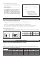
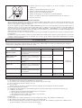
INDICATOR LIGHTS
Remote Control
When there is infrared remote control operating signal, the signal receiver on indoor unit will made a <beep> for signal
acceptance confirmation.
LED
FAULTY INDICATION
SLEEP
POWER
Room/outdoor coil sensor
missing
Blinks 4 times with 1 second interval
follow by 3 seconds interval
Indoor coil sensor missing
Blinks 4 times with 1 second interval
follow by 3 seconds interval
Compressor overload
Blinks with 1 second interval
Gas leak
Blinks 3 times with 1 second interval
follow by 3 seconds interval
Pump fault
Blinks 2 times with 1 second interval
follow by 3 seconds interval
HEAT
ACTION
Blinks with 1
second interval
Call your dealer
Blinks with 1
second interval
Outdoor defrost
–
OVERALL CHECKING
•
•
•
•
Ensure that:
1) The unit has been mounted solidly and rigid in position.
2) Piping and connections are leak proof after charging.
3) Proper wiring has been installed.
Drainage check:
– Pour some water into the main drain pipe from the flexible drain hose.
Test run:
1) Conduct a test run after water drainage test and gas leakage test.
2) Check the following items:
a. Is the electric plug firmly inserted into the socket ?
b. Is there any abnormal sound from the unit ?
c. Is there any abnormal vibration on the unit itself or piping ?
d. Is the drainage of water smooth ?
Confirm that:
1) Condenser fan is running, with warm air blowing off the condensing unit.
2) Evaporator blower is running and discharge cool air.
3) The remote control incorporate a 3 minute delay in the circuit. Thus, it requires about 3 minutes before the outdoor
condensing unit can start up.
1-12
STANDARD OPERATION CONDITIONS
Temperature
Minimum indoor
temperature
Maximum indoor
temperature
Minimum outdoor
temperature
Maximum outdoor
temperature
Ts °C / °F
Th °C / °F
19.4 / 66.9
13.9 / 57.0
26.7 / 80.1
19.4 / 66.9
19.4 / 66.9
13.9 / 57.0
46 / 114.8
24 / 75.2
Temperature
Minimum indoor
temperature
Maximum indoor
temperature
Minimum outdoor
temperature
Maximum outdoor
temperature
Ts °C / °F
Th °C / °F
10 / 50
–
26.7 / 80.1
–
-8 / 17.6
-9 / 15.8
24 / 75.2
18 / 64.4
Ts: Dry bulb temperature.
Th: Wet bulb temperature.
! Warning
•
•
Disconnect from the main power supply before servicing the air conditioner unit.
DO NOT pull out the power cord when the power is ON. This may cause serious electrical shocks which may result
in fire hazards.
AUTO RANDOM RE-START FUNCTION
If there is a power cut when the unit is operating, it will automatically resume the same operating mode when the power is
restored. (Applicable only to units with this feature)
! Caution
Before turning off the power supply, set the remote controller's ON/OFF switch to the “OFF” position to prevent the
nuisance tripping of the unit.
If this is not done, the unit's fans will start turning automatically when power resumes, posing a hazard to service
personnel or the user.
SERVICE AND MAINTENANCE
Service Parts
Indoor air filter
Maintenance Procedures
1. Remove any dust adhered on the filter by using a vacuum cleaner or
wash in lukewarm water (below 40 oC) with neutral cleaning detergent.
At least once
every 2 weeks.
2. Rinse well and dry the filter before placing it back onto the unit.
More frequently
if necessary.
3. Do not use gasoline, volatile substances or chemical to clean the filter.
Indoor unit
Period
1. Clean any dirt or dust on the grille or panel by wiping it using soft cloth
soaked in lukewarm water (below 40 oC) with neutral detergent solution.
At least once
every 2 weeks.
2. Do not use gasoline, volatile substances or chemical to clean the indoor
unit.
More frequently
if necessary.
! Caution
Do not operate any heating apparatus too close to the air conditioner unit. This may cause the plastic panel to melt or
deform as a result of the excessive heat.
1-13
English
Heat Pump Unit
Cooling unit
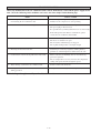
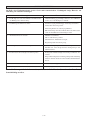
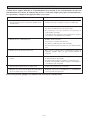
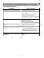
TROUBLESHOOTING
When any malfunction of the air conditioner unit is noted, immediately switch off the power supply to the
unit. Check the following fault conditions and causes for some simple troubleshooting tips.
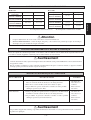
Fault
Causes / Action
1. The compressor does not start operate after 3 minutes
from starting the air conditioner unit.
- Protection against frequent starting. Wait for 3 to 4
minutes for the compressor to start operating.
2. The air conditioner unit does not operate.
-
Power failure, or the fuse need to be replaced.
The power plug is disconnected.
It is possible that your delay timer has been set incorrectly.
If the fault persist after all these verifications, please
contact the air conditioner unit installer.
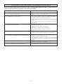
3. The air flow is too low.
-
The air filter is dirty.
The doors or windows are open.
The air suction and discharge are clogged.
The regulated temperature is not high enough.
4. Discharge air flow has bad odor.
- Odors may be caused by cigarettes, smoke particles,
perfume etc. which might have adhered onto the coil.
5. Condensation on the front air grille of the indoor unit.
- This is caused by air humidity after an extended long
period of operation.
- The set temperature is too low, increase the temperature
setting and operate the unit at high fan speed.
6. Water flowing out from the air conditioner unit.
- Switch off unit and call dealer.
7. Hissing air flow sound from the air conditioner unit
during operation.
- Refrigerant fluid flowing into the evaporator coil.
If the fault persists, please call your local dealer / serviceman.
1-14
Ce manuel fournit les procédures d’installation pour assurer le bon fonctionnement et la sécurite de cet
appareil.
Des ajustements peuvent être nécéssaires pour suivre les réglementations locales.
Avant d’installer et de faire fonctionner le climatiseur, lisez attentivement ce manuel et conservez le.
CLIMATISEUR DE PLAFOND DE TYPE CASSETTE EN DEUX PIECES
MODÈLE
FROID SEUL
REVERSIBLE
CK25B / YCK025B
SL25B / YLC025B
4SL25B / Y4LC025B
5SL25B / Y5LC025B
CK15BR / YCK015BR
SL15BR / YLC015BR
4SL15BR / Y4LC015BR
5SL15BR / Y5LC015BR
CK30B / YCK030B
SL30B / YLC030B
4SL30B / Y4LC030B
5SL30B / Y5LC030B
CK20BR / YCK020BR
SL20BR / YLC020BR
4SL20BR / Y4LC020BR
5SL20BR / Y5LC020BR
CK30B / YCK030B
SL30C / YLC30C
4SL30C / Y4LC30C
5SL30C / Y5LC30C
CK25BR / YCK025BR
SL25BR / YLC025BR
4SL25BR / Y4LC025BR
5SL25BR / Y5LC025BR
CK30BR / YCK030BR
SL30BR / YLC030BR
4SL30BR / Y4LC030BR
5SL30BR / Y5LC030BR
CK30BR / YCK030BR
SL30CR / YLC030CR
4SL30CR / Y4LC030CR
5SL30CR / Y5LC030CR
IM-CKB-0501 (2)
Part No.: A08019013026
2-1
Français
MANUEL D’INSTALLATION
SOMMAIRE
- Schéma et dimensions
- Précautions de sécurité
- Diagramme d’installation
- Installation de l’unité intérieure
- Installation de l’unité extérieure
- Tuyauterie réfrigérante
- Raccordement électrique
- Précautions spéciales en traitant l’unité de R410A
- Précautions spéciales en traitant l’unité de R407C
- Tirage au vide et charge
- Précautions Spéciales Lors du Chargement d’un
Appareil à Comresseurs Scroll de Copeland
- Indication et visualisation des états
de fonctionnement de climatiseur
- Vérifications générales
- Conditions normales de fonctionnement
- Fonction de redemarrage au hasard automatique
- Maintenance periodique du climatiseur
- Analyse des causes de dysfonctionnement
de climatiseur
page i – ii
page 2
page 3
page 3
page 6
page 6
page 8
page 10
page 10
page 11
page 11
page 12
page 12
page 13
page 13
page 13
page 14
PRÉCAUTIONS DE SÉCURITÉ
Avant de faire fonctionner l’appreil, veuillez bien lire précautions de sécurite suivantes.
! Attention
•
L’installation et la maintenance doivent être exécutées par une personne qualifiée qui est familiarisée avec les lois
et réglementations en vigueur, et aussi expérimentée dans ce type d’équipements.
•
Tous les câblages doivent répondre aux réglementations électriques nationales.
•
Avant de commencer le raccordement suivant le schéma électrique, s’assurer que la tension nominale de l’appareil
corresponde bien à celle indiquée sur la plaque signalétique.
•
L’unité doit être raccordée à la TERRE puor prévenir tous les risques possibles dûes à un défaut d’isolation.
•
Aucun câble électrique ne doit toucher la tuyauterie du réfrigérant, le compresseur ou les pièces mobiles des
moteurs de ventilation.
•
Avant l’installation ou l’entretien du climatiseur, s’assurer que l’appareil est éteint (OFF).
IMPORTANT
NE PAS INSTALLER OU UTILISER LE CLIMATISEUR DANS UNE BUANDERIE.
! Avertissement
Vérifier les points suivant au cours de l’installation.
•
Ne pas installer l’appareil où il peut se produire des fuites de gaz inflammable.
En cas de fuite et accumulation de gaz autour de l’appareil, ily a risque d’incendie.
•
S’assurer que le tuyau d’évacuation du condensat est correctement branché.
Si le tuyau d’évacuation n’est pas correctement branché, les éventuelles fuites d’eau risquent de mouiller
le mobilier.
•
Ne pas surcharger l’unité (en fluide frigorigéne).
Cet appareil est préchargé en usine. Une charge trop importante risque de provoquer une surcharge
électrique ou d’endommager le compresseur.
•
S’assurer que le panneau supérieur de l’appareil est remis en place après l’installation ou l’entretien.
Avec un panneau mal fixé l’appareil va fonctionner bruyamment.
2-2
DIAGRAMME D’INSTALLATION
Unité Intérieure
Tuyau d’evacuation
Français
Récepteur à
infrarouge
Voyant lumineux
DEL
Grille avant
Grilles de
reprise d’air
Filtre à air
(derrière la grille)
Tuyauteries Frigorifiques
Conduit de ventilation
Télécommande
ou
Télécommande sans fil
Reprise Air
Reprise Air
Refoulement d’air
Unité Extérieure
INSTALLATION DE L’UNITÉ INTÉRIEURE
Etude Preliminaire Du Site
Min. 0,5 m
Min. 0,5 m
Min. 0,5 m
Max. 0,3 m
Min. 1,0 m
•
Poutre
•
•
L’alimentation électrique et l’installation doivent être conformes à la réglementation locale (p.ex. agréé EDF).
Les fluctuations de tension du réseau doivent rester dans la limite de ±10% de la tension nominale. Le climatiseur ne doit
pas partager les lignes d’alimentation électrique avec des transformateurs de soudage, qui risquent de causer d’importantes
fluctuations.
Assurez-vous que l’emplacement est pratique pour les branchements, la tuyauterie et l’évacuation.
L’unité intérieure doit être installée de façon à ce qu’aucun obstacle ne bloque le refoulement d’air froid et l’entrée d’air
chaud et de façon à ce que l’air puisse se répandre dans la pièce (près du centre de la pièce).
Un espace doit être ménagé entre l’unité intérieure et le mur et les obstacles comme le montre la figure.
Max. 3,0 m
•
•
Obstacle
Sol
•
•
•
L’endroit d’installation doit être assez fort pour supporter une charge quatre fois supérieure au poids de l’unité intérieure
pour éviter l’amplification du bruit et des vibrations.
L’endroit d’installation (surface du plafond) doit être plane et la hauteur du plafond d’au moins 350 mm.
L’unité intérieure doit être à l’écart de sources de chaleur ou de vapeur (évitez de l’installer près d’une entrée).
2-3
Installation de l’unité
•
•
•
Mesurez et marquez l’emplacement de la tige suspendue.
Percez un trou pour l’écrou d’angle dans le plafond et fixez
la tige suspendue).
Les dimensions du gabarit d’installation sont les mêmes
que celles des dimensions de l’ouverture du plafond.
Lorsque le travail de stratification du plafond n’est pas
terminé, veillez à fixer le gabarit d’installation sur l’unité
intérieure.
REMARQUE
Assurez-vous de discuter le perçage du plafond avec
les installateurs.
Ouverture de coffrage du plafond
Accrochage de l’unité
•
•
•
•
Unité Intérieure
Coffrage
de plafond
•
35,0 mm
Confirmer le pas de la barre de suspension.
Mainrenez l’unité et accrochez-la à la tringle d’accrochage
à l’aide des écrous et des joints.
Laissez un espace de 35 mm entre la surface inférieure de
l’unité intérieure et la surface du plafond.
A l’aide d’un indicateur de niveau, assurez-vous que l’unité
est installée horizontalement et serrez l’écrou et le boulon
pour empêcher que l’unité ne tombe et ne vibre.
Ouvrez le coffrage du plafond le long du bord extérieur
du gabarit d’installation en papier.
Tuyauterie d’évacuation
•
•
Unité
Intérieure
•
Collier pour tuyaux
•
Bon
Mauvais
•
2-4
Le tuyau d’évacuation doit être incliné vers le bas pour
une évacuation facile.
Evitez de positionner le tuyau vers le haut puis vers le bas
afin d’éviter que le flux d’eau ne soit inversé.
Lorsque vous connectez les tuyaux d’évacuation, assurezvous de ne pas exercer de pression supplémentaire sur le
connecteur de l’unité intérieure.
Le diamètre extérieur du connecteur de drainage au tuyau
flexible est de 20 mm.
Assurez-vous d’isoler le tuyau d’évacuation contre la
chaleur (mousse en polyéthylène de plus de 8 mm
d’épaisseur) afin d’éviter que l’eau condensée ne.
Test d’évacuation
•
Envoyez l’eau
Tuyau d’évacuation
principal
•
Connectez le tuyau d’évacuation principal au tuyau
d’évacuation flexible.
Envoyez de l’eau dans le tuyau d’évacuation flexible et
vérifiez qu’il n’y a pas de fuite dans la tuyauterie.
Lorsque le test est terminé, connectez le tuyau flexible au
connecteur d’évacuation sur l’unité intérieure.
REMARQUE
Cette unité intérieure utilise une pompe d'evacuation pour
l'evacuation de l'eau condensee. Installez l'unite
horizontalement pour eviter que l'eau ne fuie ou ne se
condense autour du deflecteur
Tuyau
d’évacuation
flexible
Installation du panneau
•
•
•
•
OUVERT
Assurez-vous d’ôter le gabarit d’installation avant
d’installer le panneau avant.
Ouvrez la grille d’aspiration d’air en tirant le dispositif de
prise de griffes et ôtez-la avec le filtre.
Installez le panneau du cadre avant sur l’unité intérieure à
l’aide de 4 vis et serrez-les complètement pour éviter que
l’air froid ne s’échappe.
Joindre le cable LED á l’unité intérieure.
Armoire de commande
Fil de la DEL
Du panneau avant
REMARQUE
Installez le panneau du cadre avant fermement pour éviter
que l’air froid ne s’échappe, que de la condensation ne se
forme et que de l’eau ne goutte.
Vis
Unite Interieure
Air
froid
Air
froid
Fuite d’air
Fuite d’air
Coffrage
de plafond
Coffrage
de plafond
Avant
Avant
Installation correcte
Installation mauvais
2-5
Français
•
Installation de la grille d’aspiration
•
•
•
•
•
•
Avant d’installer la grille d’arrivée d’air, assurez-vous
que le filtre à air soit bien fixé à la grille d’arrivée d’air.
Installez la grille d’aspiration avec le filtre à air sur le
panneau avant.
La grille peut être installée dans n’importe quelle
direction, lorsque vous choisissez la direction, prenez
en compte le dessin du plafond et l’accessibilité de la
grille.
Dans le cas où l’unité est vendue avec le filtre ioniseur
(en option), veillez à bien fixer le filtre ioniseur au filtre
à air avant d’installer la grille d’arrivée d’air.
Fixez le filtre ionisant au filtre à air, côté noir au-dessus,
côté blanc au-dessous.
Attachez soigneusement le cadre du filtre ionisant.
Filtre
Ionisant
Cadre
INSTALLATION DEL L’UNITÉ EXTÉRIEURE
Etude Preliminaire Du Site
•
Un endroit protégé de la pluie, des rayons directs du soleil et bien aéré lorsque c’est possible.
•
Un endroit pouvant supporter le poids de l’unité extérieure et d’isoler le bruit et les vibrations.
•
Un endroit sans obstruction du flux d’air entrant et sortant de l’unité.
•
Ne placez aucun objet pouvant faire obstacle au flux d’air entrant et sortant de l’unité extérieure.
•
L’endroit doit être abrité de la poussière, de l’huile, du sel ou de gaz sulfureux.
Installation de l’unité extérieure
•
Installez l’unité extérieure fermement et horizontalement. Ménagez un espace intermédiaire comme illustré ci-dessous
pour l’entretien et le flux d’air.
A
B
C
D
Série SL
A
B
C
D
Distance min, mm (pouce)
300
1000
300
500
(11,8) (39,4) (11,8) (19,7)
TUYAUTERIE RÉFRIGÉRANTE
La tuyauterie frigorifique est particulièrement importante. Le cycle de réfrigération du climatiseur d’air en
deux pièces est possible grâce à une tuyauterie parfaite.
Longueur et élévation des tuyaux
Pour un bon fonctionnement des unités, il est impératif de respecter la longueur maximum des tuyauteries (L) indiquée dans
le tableau ci-dessours, de respecter le nombre de coudes maximum autorisé, et de ne pas dépasser la différence de niveau (H)
entre l’unité intérieure et l’unité extérieure.
Intérieure
Extérieure
Longueur max, m (pieds)
Elevation max, m (pieds)
Nombre de coude max
Ø racc. tube liquide
Ø racc. tube aspiration
Modéle
CK15B/BR
SL15B/BR
12 (39)
5 (16)
10
1/4”
1/2”
CK20B/BR
SL20B/BR
15 (49)
8 (26)
10
1/4”
5/8”
2-6
CK25B/BR
SL25B/BR
15 (49)
8 (26)
10
3/8”
5/8”
CK30B/BR
SL30B
35 (114)
8 (26)
10
3/8”
5/8”
CK30B/BR
SL30C/CR
35 (114)
15 (49)
10
3/8”
5/8”
•
•
•
•
•
•
•
Ne pas utiliser de tuyauteries en cuivre encrassé ou endommagé. Si les tuyauteries, l’évaporateur ou le condenseur sont
restés exposés ou ouverts pendant plus de 15 secondes, il faut effectuer un tirage au vide et les recharger en réfrigérant
fourni localement. D’une manière générale, ne pas retirer les bouchons en plastique ou caoutchouc et les écrous en laiton
des vannes, raccords, tubes et serpentins jusqu’à ce que les tuyauteries d’apiration ou de liquide soient prêtes à être
connectées aux vannes et raccords.
S’il est nécessaire de braser, s’assurer que de l’azote passe dans les serpentins et raccords pendant le brasage, pour éviter
les dépôts de suie sur les faces intérieures des tubes de cuivre.
Couper les tuyaux progressivement, en faisant avancer la lame du coupe-tube lentement. Une coupe profonde et forcée va
déformer le tube davantage et ainsi causer plus de bavures.
Otez la bavure de découpage des bouts coupés des tuyaux à l’aide d’un ébarbeur. Ceci empêchera que la face de la partie
évasée ne soit irrégulière, ce qui serait à l’origine de fuites de gaz.
Alignez le centre de la tuyauterie et serrez suffisamment l’écrou flare avec les doigts. Enfin, serrez l’écrou flare à l’aide
d’une clé dynamométrique à déclenchement jusqu’à ce qu’elle cliquette.
Assurez-vous d’isoler contre la chaleur. (mousse polyuréthanne de plus de 15 mm d’épaisseur)
Hormis pour l’unité extérieure pré-chargée de réfrigérant R22, l’unité intérieure et les tuyaux réfrigérants de connexion
doivent être purgés car l’air contient de l’humidité restant dans le cycle frigorifique qui peut causer un mauvais
fonctionnement du compresseur.
Charge Supplémentaire
Le réfrigérant est pré-chargé dans l’unité extérieure mais du réfrigérant supplémentaire est nécessaire après avoir aspiré.
Suivez les recommandations données ci-dessous.
Froid Seul (R22 / R407C)
Modéle
Intérieure
Extérieure
L <= 5 m
L=7m
L = 10 m
L = 15 m
L = 20 m
CK15B
SL15B
0,250 kg
0,300 kg
0,325 kg
0,400 kg
–
CK20B
SL20B
0,250 kg
0,280 kg
0,325 kg
0,400 kg
–
CK25B
SL25B
0,100 kg
0,176 kg
0,290 kg
0,480 kg
–
CK30B
SL30B
0,100 kg
0,200 kg
0,350 kg
0,600 kg
0,850 kg
CK30B
SL30C
0,400 kg
0,600 kg
0,650 kg
0,900 kg
1,150 kg
Reversible (R22 / R407C)
Modéle
L <= 5 m
L=7m
L = 10 m
L = 15 m
L = 20 m
Intérieure
Extérieure
CK15B
SL15BR
–
0,050 kg
0,075 kg
0,150 kg
–
CK20BR
SL20BR
–
0,050 kg
0,075 kg
0,150 kg
–
CK25BR
SL25BR
–
0,100 kg
0,500 kg
0,750 kg
–
CK30BR
SL30CR
–
0,100 kg
0,250 kg
0,500 kg
0,750 kg
Froid Seul (R410A)
Modéle
L <= 5 m
L=7m
L = 10 m
L = 15 m
L = 20 m
CK15B
0,225 kg
0,270 kg
0,293 kg
0,360 kg
–
CK20B
0,225 kg
0,252 kg
0,293 kg
0,360 kg
–
CK25B
0,090 kg
0,159 kg
0,261 kg
0,432 kg
–
CK30B
0,090 kg
0,180 kg
0,315 kg
0,541 kg
0,766 kg
CK30B
0,360 kg
0,541 kg
0,586 kg
0,811 kg
1,036 kg
Reversible (R410A)
Modéle
L <= 5 m
L=7m
L = 10 m
L = 15 m
L = 20 m
CK15BR
–
0,045 kg
0,068 kg
0,135 kg
–
CK20BR
–
0,045 kg
0,068 kg
0,135 kg
–
2-7
CK25BR
–
0,090 kg
0,450 kg
0,676 kg
–
CK30BR
–
0,090 kg
0,225 kg
0,450 kg
0,676 kg
Français
Connexion des tuyaux
RACCORDEMENT ÉLECTRIQUE
Froid Seul
CK15B / CK20B / CK25B & CK30B
Intérieure
Extérieure
Alimentation-Plage De Tension**
Section Du Câble D’alim*
mm2
Nombre De Conducteurs
Section Du Câble De Liasion*
mm2
Nombre De Conducteurs
Modéle
IMPORTANT:
CK15B
CK20B
CK25B
CK30B
CK30B
SL15B
SL20B
SL25B
SL30B
SL30C
220 – 240V /1Ph /50Hz + ! ou 208 – 230V /1Ph /60Hz + !
1,5
2,5
2,5
4,0
4,0
3
3
3
3
3
1,5
2,5
2,5
2,5
2,5
3
3
3
3
4
* Les valeurs sont données à titre indicatif. Elles doievent être vérifiées et ajustées en fonction des normes
en vigueur. Elles dépendent du mode de pose et du choix des conducteurs.
** Le voltage adéquat doit être vérifié avec les données de l’étiquette sur l’appareil. ETL n’est applicable que
pour une alimentation électrique de 60Hz.
CK15B / 20B / 25B / 30B <> SL15B / 20B / 25B / 30B
COMP
Câble de Liaison
COMP Bornier De L’Unité
Extérieure
L
Bornier de
L’Unité
Intérieure
N
N
N
Cordon Electrique
!
L'alimentation doit être munie d'un dispositif de
protection (disjoncteur ou fusible) ayant un
système de séparation omnipolaire (phase +
neutre) avec une distance d'ouverture des
contacts d'au moins 3mm.
CK30B <> SL30C
S
Condensateur
COMP
Bornier de
L’Unité
Intérieure
R
Câble de Liaison
COMP
L
L
N
Bornier De L’Unité
Extérieure
N
L
N
Cordon Electrique
!
2-8
L'alimentation doit être munie d'un dispositif de
protection (disjoncteur ou fusible) ayant un
système de séparation omnipolaire (phase +
neutre) avec une distance d'ouverture des contacts
d'au moins 3mm.
Reversible
Modéle
Intérieure
Extérieure
Alimentation-Plage De Tension**
Section Du Câble D’alim*
mm2
Nombre De Conducteurs
Section Du Câble De Liasion*
mm2
Nombre De Conducteurs
IMPORTANT:
CK15BR
CK20BR
CK25BR
CK30BR
SL15BR
SL20BR
SL25BR
SL30CR
220 – 240V /1Ph /50Hz + ! ou 208 – 230V /1Ph /60Hz + !
1,5
2,5
2,5
4
3
3
3
3
1,5
2,5
2,5
2,5
5
5
5
6
* Les valeurs sont données à titre indicatif. Elles doievent être vérifiées et ajustées en fonction des normes
en vigueur. Elles dépendent du mode de pose et du choix des conducteurs.
** Le voltage adéquat doit être vérifié avec les données de l’étiquette sur l’appareil. ETL n’est applicable que
pour une alimentation électrique de 60Hz.
CK15BR / 20BR / 25BR <> SL15BR / 20BR / 25BR
Sonde de L’ Unité Extérieure
4WV
OF
4WV
OF
Câble de Liaison
COMP
Bornier de
L’Unité
Intérieure
COMP
L
N1
Bornier De
L’Unité
Extérieure
N
N2
Cordon
Electrique
!
2-9
L'alimentation doit être munie d'un dispositif de
protection (disjoncteur ou fusible) ayant un
système de séparation omnipolaire (phase +
neutre) avec une distance d'ouverture des contacts
d'au moins 3mm.
Français
CK15BR / CK20BR / CK25BR / CK30BR
CK30BR <> SL30BR / CR
Sonde de L’ Unité Extérieure
A
A
4WV
4WV
OF
OF
Bornier de
L’Unité
Intérieure
Câble de Liaison
COMP
COMP
L
L
Bornier De
L’Unité
Extérieure
N
N
L
Cordon Electrique
N
!
L'alimentation doit être munie d'un dispositif de
protection (disjoncteur ou fusible) ayant un
système de séparation omnipolaire (phase +
neutre) avec une distance d'ouverture des contacts
d'au moins 3mm.
PRÉCAUTIONS SPÉCIALES EN TRAITANT L'UNITÉ DE R410A
R410A est un nouveau réfrigérant de HFC qui n'endommage
pas la couche d'ozone. La pression d'utilisation de ce nouveau
réfrigérant est 1.le réfrigérant 6 fois plus haut que
conventionnel (R22), ainsi installation/servicing approprié est
essentiel.
• Jamais réfrigérant de l'utilisation autre que R410A dans
un climatiseur qui est conçu pour fonctionner avec R410A.
• De l'huile de POE est employée comme lubrifiant pour le
copressor de R410A, qui est différent de l'huile minérale
utilisée pour le compresseur R22. Pendant l'installation
ou l'entretien, la précaution supplémentaire doit être prise
pour ne pas exposer le système de R410A trop long à l'air
moite. L'huile résiduelle de POE dans la tuyauterie et le
cn de composants absorbent l'humidité de l'air.
• Pour empêcher mischarging, le diamètre du port de service sur la valve de fusée est différent de celui de R22.
•
•
•
•
Employez les outils et les matériaux exclusivement pour
le réfrigérant R410A. Les outils exclusivement pour
R410A sont valve diverse, tuyau de remplissage, indicateur
de pression, détecteur de fuite de gaz, outils de fusée, clé
dynamométrique, pompe de vide et cylindre de réfrigérant.
Car un climatiseur de R410A encourt une pression plus
élevée que les unités R22, il est essentiel de choisir les
pipes de cuivre correctement. Jamais diluant de cuivre de
pipes d'utilisateur que 0,8mm quoiqu'ils soient disponibles
sur le marché.
Si le gaz de réfrigérant fuit pendant l'installation /servicing, soyez sûr d'aérer entièrement. Si le gaz réfrigérant
entre en contact avec le feu, un gaz toxique peut se produire.
En installant ou en enlevant un climatiseur, ne laissez pas
l'air ou l'humidité rester dans le cycle réfrigérant.
PRÉCAUTIONS SPÉCIALES EN TRAITANT L’UNITÉ DE R407C
•
•
•
R407C est un mélange réfrigérant zeotropic qui a le
potentiel nul d'épuisement de l’ozone et conforme ainsi
au règlement de protocole de Montréal. Il exige l’huile de
l’huile d’ester de polyol (POE) pour le lubrifiant de son
compresseur. Sa capacité et exécution réfrigérantes sont
plus ou moins comme le réfrigérant R22.
De l’huile de POE est employée comme lubrifiant pour le
compresseur de R407C, qui est différent de l’huile minérale
utilisée pour le compresseur R22. Pendant l’installation
ou l’entretien, la précaution supplémentaire doit être prise
pour ne pas exposer le système de R407C trop long à l’air
moite. L’huile résiduelle de POE dans la tuyauterie et les
composants peuvent absorber l’humidité de l’air.
Le réfrigérant R407C plus facilement est affecté par la
poussière de l’humidité comparée à R22, veillent à couvrir
temporairement les extrémités de la tuyauterie avant
l’installation.
•
•
•
•
2-10
Aucune charge additionnelle d’huile de compresseur n’est
autorisée.
Aucun autre réfrigérant autre que R407C.
Outils spécifiquement pour R407C seulement (ne doit pas
être employé pour R22 ou tout autre réfrigérant)
i)
Mesure diverse et tuyau de remplissage
ii) Détecteur de fuite de gaz
iii) Cylindre réfrigérant de cylinder/charging
iv) Adapteur de la pompe de vide c/w
v) Outils de fusée
vi) Machine réfrigérante de rétablissement
Le Filtre-dessiccateur doit être installé suivant la ligne
liquide pour tous les climatiseurs de R407C. Ce doit
réduire au minimum la contamination de l’humidité et de
la saleté dans le système réfrigérant.le Filtre-dessiccateur
doit être de type de passoir moléculaire. Pour un système
de heat-pump, installez un dessiccateur bi-directionnel de
filtre d’écoulement suivant la ligne liquide.
TIRAGE AU VIDE ET CHARGE
Aspiration
Charge
Avant d’aspirer, assurez-vous qu’il n’y a pas de fuite dans le
circuit frigorifique. Après que la tuyauterie du système est
connectée correctement, connectez les tuyaux flexibles aux
manchons filetés. Assurez-vous que le tuyau flexible des
manchons filetés soient connectés à la pompe d’aspiration au
moyen de valves de service standard et aux jauges de pression
(manomètre d’admission). Aspirez l’air du système de
climatisation à au moins 500 microns Hg. Ne mettez pas
l’unité en marche pendant l’aspiration.
Avant de charger, le vide doit être maintenu à 500 microns
Hg pendant au moins 15 minutes, puis vérifiez le vide en
chargeant le réfrigérant R-22. Faites tourner l’unité pendant
15 minutes et assurez-vous que la charge du réfrigérant est
correcte en contrôlant le courant, la pression du gaz et des
canalisations de liquide. L’aspiration et la pression du tuyau
de refoulement devraient être de l’ordre de 75 psi et 275 psi
en général.
Après vous être assuré que le système est chargé correctement,
ôtez le tuyau flexible des manchons filetés et remettez le
bouchon femelle en place.
PRÉCAUTIONS SPÉCIALES LORS DU CHARGEMENT D’UN APPAREIL
À COMPRESSEURS SCROLL DE COPELAND
Ces précautions visent uniquement les compresseurs Scroll de Copeland avec des frigorigènes R22, R407C, R134A, R404A,
R507 et R410A et non pas les compresseurs à piston Copeland ou les compresseurs à volute concurrents.
Les compresseurs Scroll ont une efficacité volumétrique très élevée et pompent rapidement un vide profond si l’appareil
manque de frigorigène ou si l’adduction de frigorigène est trop lente. Le fonctionnement à pression d'aspiration basse génère
vite des températures de refoulement très élevées. Pendant ce temps, les volutes ne sont pas bien lubrifiées, car leur lubrification
dépend du brouillard d'huile dans le frigorigène. Un graissage insuffisant entraîne une grande friction entre les faces et les
extrémités des volutes, ce qui produit encore plus de chaleur. La chaleur de compression combinée à la chaleur découlant de
la friction accrue se concentre dans une zone de refoulement réduite, où les températures peuvent rapidement dépasser 300°C.
Ces températures extrêmes abîment les spirales de volute et le support de volute en rotation. Cet endommagement peut se
produire en moins d’une minute, surtout dans les gros compresseurs. Il peut y avoir une panne dans les quelques premières
heures ou les dommages infligés au cours du chargement local peuvent se faire sentir un certain temps après.
Les autres défauts habituels du chargement local incluent le sous-chargement, le surchargement, la présence d’humidité ou
d’air dans le dispositif, etc. Avec le temps, chacune de ces anomalies peuvent mettre le compresseur en panne.
Il faut très peu d’équipement pour effectuer un chargement local satisfaisant :Jeu de manomètres de moteur
Vacuomètre
Tuyaux flexibles
Balances
Pompe à vide
Thermomètre
Une charge de frigorigène adéquate doit correspondre au volume recommandé par le fabricant, et cette recommendation
devrait être suivie par l’installateur.
1. Méthode de chargement - compresseurs monophasés
Vider le dispositif jusqu’à l’obtention de 500 microns de mercure Hg. (67 Pa). Pour réduire le délai de purge, utiliser des
flexibles courts à grand diamètre et les raccorder à des orifices de service sans restriction de l’appareil. On ne peut pas
évaluer la qualité du vide selon le délai - il faut employer un vacuomètre fiable (vacuomètre électronique, etc.).
Tourner la bouteille de frigorigène à l’envers, purger le flexible de charge et alimenter en liquide au moyen de l’orifice de
chargement de la conduite de liquide jusqu’à ce que le frigorigène ne coule plus ou jusqu’à ce qu’une charge de poids
adéquate soit atteinte. Si une charge supplémentaire est requise, démarrer l’appareil et infiltrer lentement du liquide dans
le côté basse pression jusqu’à ce que le dispositif soit plein.
Copeland recommande de charger le liquide de façon CONTRÔLÉE dans le côté basse pression jusqu’à ce que le
dispositif soit plein. Cette recommandation ne s’applique pas aux compresseurs à piston, qui risquent d’être gravement
endommagés par le chargement de liquide dans le côté basse pression.
Surveiller attentivement les pressions d'aspiration et de refoulement - la pression manométrique d'aspiration ne doit jamais
tomber sous 25 psig (1,7 bar) au cours du chargement.
! Avertissement
•
Le manomètre du collecteur indique la pression de la bouteille au lieu de la pression d'aspiration si le robinet
de la bouteille et la soupape “A” du collecteur sont ouverts tous les deux.
2-11
Français
Aspirer est nécessaire pour éliminer toute humidité et air du système. La série II Unité Intérieure est fournie avec des raccords
de valve flare.
A
Il y a bien des façons de charger le liquide de manière “contrôlée” dans le côté basse
pression:1. Utiliser la soupape A sur le groupe manomètre du collecteur.
2. Recourir au robinet sur la bouteille de frigorigène.
3. Charger par l’intermédiaire d’une valve Shredder.
4. Employer un flexible muni d’un dépresseur de valve Shredder.
5. Charger dans le côté basse pression à une certaine distance du compresseur.
6. Tous les moyens ci-dessus.
2. Méthode de chargement - compresseurs triphasés
La méthode de base est la même que pour les modèles monophasés, mais le compresseur peut tourner dans la mauvaise
direction au démarrage. Si cela se produit, inverser deux phases (n’importe lesquelles) et redémarrer. Une rotation inversée
de courte durée n’endommagera pas le compresseur.
Tous les compresseurs Specter (Modéle: ZR90 á ZR19M) disposent de protections internes contre la température de
refoulement, qui préviennent très efficacement les températures de refoulement dangereusement élevées en cours de
chargement. Le module de protection se déclenchera et verrouillera les compresseurs pendant 30 minutes. Il n’est
normalement pas nécessaire d’attendre 30 minutes pour réinitialiser le module. Une fois le compresseur refroidi, le module
peut être réinitialisé en coupant l’alimentation du circuit de commande. Très souvent, le mécanicien d'entretien ne comprend
pas pourquoi le module s’est déclenché et se sert d’un cavalier pour le contourner. Il continue de charger l’appareil et retire
le cavalier à la fin du chargement. Le compresseur fonctionnera peut-être avec la protection réintégrée dans le circuit, mais
il est certain que le compresseur a été endommagé et qu’une panne prématurée est inévitable.
INDICATION ET VISUALISATION DES ÉTATS DE FONCTIONNEMENT DE CLIMATISEUR
Télécommande
Lorsqu’il y a un signal d’opération de télécommande à infrarouge, le récepteur du signal de l’unité intérieure émet un <bip>
en confirmation de l’acceptation du signal.
LED
INDICATION DE
FONCTIONNEMENT
PUISSANCE
Capteur à resort pour
intérieur/extérieur manquant
Clignote 4 fois avec une seconde
d’intervalle, suivi de 3 secondes d’intervalle
Détecteur à bobine interne
manquant
Clignote 4 fois avec une seconde
Clignote avec une
d’intervalle, suivi de 3 secondes d’intervalle seconde d’intervalle
Surcharge du compresseur
Clignote avec une seconde d’intervalle
Perte de gaz
Clignote 3 fois avec une seconde
d’intervalle, suivi de 3 secondes d’intervalle
Défectuosité de la pompe
Clignote 2 fois avec une seconde
d’intervalle, suivi de 3 secondes d’intervalle
SOMMEIL
CHALEUR
Contacter votre
revendeur
Clignote avec une
seconde d’intervalle
Dégel extérieur
ACTION
–
VÉRIFICATIONS GÉNÉRALES
•
•
•
•
Contrôle des points suivants:
1) L’appareil est solidement installé et ne bouge pas.
2) Les tuyauteries et raccords sont étanches après la mise en charge.
3) Le câblage est fait correctement.
Vérification de l’évacuation:
– Versez de l’eau dans le tuyau d’évacuation principal à partir du tuyau d’évacuation flexible.
Test de fonctionnement:
1) Faire un test de fonctionnement après avoir vérifié l’écoulement de l’eau et l’étanchéité au gaz.
2) Vérification des points suivants:
a. La fiche électrique est-elle bien branchée dans la prise?
b. Y a-t-il des bruits anormaux venant de l’appareil?
c. Y a-t-il des vibrations anormales au niveau de l’appareil ou de la tuyauterie?
d. L’évacuation de l’eau se fait-elle sans problème?
Contrôle des points suivants:
1) Le ventilateur du condenseur est en marche avec de l’air chaud soufflant de l’unité.
2) Le ventilateur de l’évaporateur tourne et dégage de l’air froid.
3) La télécommande incorpore un délai de 3 minutes dans le circuit. Ainsi, il faut environ 3 minutes avant que l’unité de
condensation extérieure ne démarre.
2-12
CONDITIONS NORMALES DE FONCTIONNEMENT
Reversible
Température
Ts °C / °F
Température
intérieure minimum
Température
intérieure maximum
Température
extérieure minimum
Température
extérieure maximum
Température
Th °C / °F
19,4 / 66,9
13,9 / 57,0
26,7 / 80,1
19,4 / 66,9
19,4 / 66,9
13,9 / 57,0
46 / 114,8
24 / 75,2
Température
intérieure minimum
Température
intérieure maximum
Température
extérieure minimum
Température
extérieure maximum
Ts: Température au thermomètre sec.
Ts °C / °F
Th °C / °F
10 / 50
–
26,7 / 80,1
–
-8 / 17,6
-9 / 15,8
24 / 75,2
18 / 64,4
Th: Température au thermomètre mouillé.
! Attention
•
•
Couper l’alimentation du secteur avant d’effectuer l’entretien du climatiseur.
NE PAS DÉBRANCHER le cordon électrique lorsqu’il y a du courant. Ceci pourrait provoquer des décharges
électriques avec pour résultat des risques d’incendie.
FONCTION DE REDEMARRAGE AU HASARD AUTOMATIQUE
En cas de coupure de courant lorsque l’unité est en marche, celle-ci redémarre selon le même mode d’opération une fois que
le courant est rétabli. (Applicable seulement pour les unités munies de cette fonction)
! Avertissement
Avant de débrancher l’unité, réglez l’interrupteur de la télécommande sur la position OFF afin d’éviter le déclenchement
inopportun de l’unité.
En cas d’oubli, le ventilateur se remet en marche automatiquement dès que le courant est rétable, ce qui peut constituer
un risque pour le personnel d’entretien ou pour les usagers.
MAINTENANCE PERIODIQUE DU CLIMATISEUR
Pieces a Entretenir
Procédure D’entretien
Périodicité
Filtre à air intérieur
1. Enlever la poussière du filtre à l’aide d’un aspirateur ou en lavant le
filtre à l’eau tiède (moins de 40°C) avec un détergent neutre.
2. Bien rincer et sécher le filtre avant de le remettre en place.
3. Ne pas utiliser de gasoil, de substances volatiles ou autres produits
chimiques pour nettoyer le filtre.
Au moins une
fois toutes les 2
semaines.
Plus souvent si
nécessaire.
Unité intérieure
1. Nettoyer la grille et le panneau en les essuyant avec un chiffon doux
mouillé à l’eau tiède (moins de 40°C) et un détergent neutre.
Au moins une
fois toutes les 2
semaines.
Plus souvent si
nécessaire.
2. Ne pas utiliser de gasoil, de substances volatiles ou autres produits
chimiques pour nettoyer l’unité intérieure.
! Avertissement
Ne pas utiliser d'appareil de chauffage à proximité du climatiseur. La chaleur excessive pourrait faire fondre ou déformer
le panneau en plastique.
2-13
Français
Froid Seul
ANALYSE DES CAUSES DE DYSFONCTIONNEMENT DE CLIMATISEUR
En cas de dysfonctionnement du climatiseur, couper aussitôt l’alimentation électrique. Vérifier ensuite les
points suivants pour détecter la nature et les causes de la panne.
Defauts
Causes / Action
1. Le compresseur ne démarre pas 3 minutes après la
mise en marche du climatiseur.
- Protection contre les démarrages fréquents. Laisser 3 à 4
minutes au compresseur pour démarrer.
2. Le climatiseur ne fonctionne pas.
- Le circuit est peut être coupé ou un fusible est à changer.
- La prise de courant est peut être débranchée.
- La programmation de mise en marche/arrêt est peut-être mal
réglée.
- Si la panne persiste après ces vérifications, contacter
l’installateur.
3. Le flux d’air est trop faible.
-
4. L’air dégagé a une mauvaise odeur.
- Les odeurs peuvent provenir de fumées de cigarettes,
parfums ou autres particules adhérants au refroidisseur.
5. Condensation sur la grille frontale de l’unité intérieure.
- La condensation est due à l’humidité de l’air après une
période de fonctionnement prolongée.
- La température affichée est trop basse; augmenter la
température et faire tourner l’appareil à vitesse de ventilation
élevée.
6. Ecoulement d’eau du climatiseur.
- Vérifier l’évacuation des condensats.
7. Bruit de chuintement venant du climatiseur.
- Le fluide réfrigérant coule dans le serpentin de l’évaporateur.
Le filtre à air est sale.
Les portes ou les fenêtres sont ouvertes.
Les entrées et sorties d’air sont bouchées.
La température réglée n’est pas assez élevée.
Si les pannes persistent, appeler votre revendeur ou le service après-vente.
2-14
INSTALLATION HANDBUCH
Das vorliegende Handbuch enthält die Installationsanweisungen für einen sicheren und ordnungsgemäßen Betrieb
dieser Anlage.
Je nach den örtlichen Gegebenheiten können spezielle Anpassungen notwendig sein.
Vor der Inbetriebnahme des Klimagerätes dieses Handbuch bitte aufmerksam zur Kenntnis nehmen und für
künftigen Bedarf aufbewahren.
Deutsch
ZWEITEILIGE KLIMAANLAGE FÜR ABGEHÄNGTE DECKEN
MODELL
KÜHLEN
HEIZEN
CK25B / YCK025B
SL25B / YLC025B
4SL25B / Y4LC025B
5SL25B / Y5LC025B
CK15BR / YCK015BR
SL15BR / YLC015BR
4SL15BR / Y4LC015BR
5SL15BR / Y5LC015BR
CK30B / YCK030B
SL30B / YLC030B
4SL30B / Y4LC030B
5SL30B / Y5LC030B
CK20BR / YCK020BR
SL20BR / YLC020BR
4SL20BR / Y4LC020BR
5SL20BR / Y5LC020BR
CK30B / YCK030B
SL30C / YLC30C
4SL30C / Y4LC30C
5SL30C / Y5LC30C
CK25BR / YCK025BR
SL25BR / YLC025BR
4SL25BR / Y4LC025BR
5SL25BR / Y5LC025BR
CK30BR / YCK030BR
SL30BR / YLC030BR
4SL30BR / Y4LC030BR
5SL30BR / Y5LC030BR
CK30BR / YCK030BR
SL30CR / YLC030CR
4SL30CR / Y4LC030CR
5SL30CR / Y5LC030CR
IM-CKB-0501 (2)
Part No.: A08019013026
3-1
INHALT
- Auslegung und Admessung
- Vorsichtmaßnahmen
- Instalationsdiagramm
- Installation des Innengerätes
- Installation des Außengerätes
- Kühlrohrleitungen
- Kabelanschluß
- Spezielle Vorkehrungen Beim
Beschäftigen R410A Maßeinheit
- Spezielle Vorkehrungen Beim
Beschäftigen R407C Maßeinheit
seite i – ii
seite 2
seite 3
seite 3
seite 6
seite 6
seite 8
- Vakuumherstellung und Laden
- Besondere Vorsichtsmassnahmen bei der
Nachfüllung von Copelan-scroll-verdichtern
- Betriebsleuchtanzeige
- Komplettprüfung
- Standard-Betriebsbedingung
- Automatische nicht-zeitgebundene
Wiedereinschaltungsfunktion
- Instandhaltung u. Wartung
- Störungsbehebung
seite 10
seite 11
seite 11
seite 12
seite 12
seite 13
seite 13
seite 13
seite 14
seite 10
VORSICHTMAßNAHMEN
Vor der Installation sind nachfolgende Sicherheitsmaßnahmen aufmerksam zur Kenntnis zu nehmen.
! Achtung
•
•
•
•
•
•
Die Installation und Wartung muß durch qualifizietes Personal erfolgen, Welches mit den örtlichen Bestimmungen
und diesem Ausrüstungstyp vertraut ist.
Die gesamte E-Verkabelung hat in Übereinstimmung mit den landesspezifischen Anschlußvorschriften zu erfolgen.
Vor dem Kabelanschluß gemäß Schaltbild ist sicherzustellen, daß die Betriebsspannung mit der auf dem Datenschild
des Gerätes angegebenen Spannung übereinstimmt.
Das Gerät ist zum Schutz gegen fehlerhafte Isolierungen und entsprechende Risiken zu ERDEN.
Die Kabel dürfen weder mit der Kühlmittelleitung, noch mit dem Kompressor oder den beweglichen Teilen der
Gebläsemotoren in Berührung kommen.
Vor der Installation oder Wartung der Anlage ist sicherzustellen, daß das Gerät ausgeschaltet ist
WICHTIG
DAS KLIMAGERÄT SOLLTE NICHT IN EINEM WÄSCHERAUM INSTALLIERT ODER BENUTZT WERDEN.
! Vorsicht
Vor der installation sind folgende wichtige punkte zu prüfen.
• Gerät nicht installieren, falls ein Leck entzündbaren gases festgestellt wird.
Es besteht Feuergefahr, wenn Gas aus der Anlage entweicht und sich in der Umgebung ansammelt.
• Die Kondensat-Abflußleitung muß sachgemäß angeschlossen sein.
Ist die Abflußleitung nicht richtig angeschlossen, besteht Gefahr, daß durch auslaufendes Wasser das
Mobiliar feucht wird.
• Gerät nicht überlasten.
Das Gerät ist werkseitig vorgefüllt. Im Falle einer Überfüllung besteht die Gefahr einer Überbelastung
oder sonstigen Beschädigung des Kompressors.
• Nach Installation oder Wartung ist sicherzustellen, daß die Geräteabdeckung wieder montiert ist.
Eine mangelhafte Befestigung der Abdeckung führt zu Geräuschentwicklung während des Betriebs.
3-2
INSTALATIONSDIAGRAMM
Innen-Gerät
Ablaufschlauch
Infrarot-Empfänger
Leuchtdiode (LED)
Frontpaneel
Lufteinlassgitter
Luftfilter
(hinter Jalousie)
Kältemittelleitung
Abluftaufsatz
Fernbedienung
Deutsch
und
Infrarot-Fernbedienung
Lufteinlass
Lufteinlass
Luftauslaß
Außen-gerät
INSTALLATION DES INNENGERÄTES
Vorbereitende Massnahmen
•
•
•
•
•
•
•
•
Stromversorgung und Installation hat in Übereinstimmung mit den landesspezifischen Vorschriften zu erfolgen.
Netzspannungsschwankungen dürfen nicht um mehr als ±10% von der Nennspannung abweichen. Die Stromleitungen
dürfen nicht zusammen mit Schweißtransformatoren auf einem Stromkreis liegen, da diese hohe Spannungsschwankungen
verursachen können.
Achten Sie darauf, daß der Installationsort für die Verkabelung, die Rohrleitungsführung und die Ablaufleitungen geeignet
ist.
Das Raumgerät muß so installiert werden, daß der Kühlluftauslaß und der Warmlufteinlaß nicht blockiert werden können
und die Kühlluft gleichmäßig über den Raum verteilt werden kann (nahe Raummitte).
Das Raumgerät muß entsprechend der Abbildung ausreichend weit entfernt von Wänden und anderen Hindernissen installiert
werden.
Der Installationsorts muß zwecks Vermeidung von Geräusch- und Vibrationsverstärkung das Vierfache der Last des
Raumgeräts tragen können.
Der Installationsort (abgehängte Decke) muß waagerecht sein und einen Hohlraum von mindestens 350 mm aufweisen.
Das Raumgerät muß abseits von Wärme- und Dampfquellen installiert werden (möglichst nicht in der Nähe von).
3-3
Installation des Geräts
•
•
•
Messen und markieren Sie die Position der Abhängstange.
Bohren Sie das Loch für die Winkelmutter in die Decke
und befestigen Sie die Abhängstange.
Die Abmessungen der Installationsschablone sind
identisch mit den Abmessungen der Deckenöffnung.
Wenn die Deckenverkleidung noch nicht fertiggestellt ist,
muß die Installationsschablone am Raumgerät angebracht
werden.
HINWEIS
Besprechen Sie die Deckenbohrungen mit den
zuständigen Installateuren.
Öffnung im Deckenpaneel
Abgehängtes Raumgerät
•
•
•
•
Innen-Gerät
Deckenpaneel
•
Die Neìgung der Aufhängestange ist zu prüfen.
Das Gerät anheben und mit Hilfe von Mutter und
Unterlegscheibe an der Aufhängestange anbringen.
Justieren Sie die Höhe des Raumgeräts auf 35 mm
zwischen Geräteunterseite und Abhängdecke.
Überprüfen Sie mit einer Wasserwaage, ob das gerät
waagerecht installiert ist, und ziehen Sie die Bolzenmutter
zur Vorbeugung von Vibrationen fest an.
Öffnen Sie das Deckenpaneel entlang der Außenkante der
Installationsschablone.
35,0 mm
Ablaßrohrleitungen
•
•
Innen-Gerät
•
Rohrschelle
•
Richtig
Falsch
•
3-4
Ablaßrohrleitung muß für störungsfreien Ablauf lotrecht
installiert werden.
Vermeiden Sie zur Vorbeugung gegen Wasserrückfluß
jegliche Gefälle oder Steigungen beim Installieren der
Ablaufrohrleitung.
Achten Sie darauf, daß der Ablaufanschluß am Raumgerät
beim Anschließen der Ablaufrohrleitung nicht übermäßig
belastet wird.
Der Ablaufanschluß hat des flexiblen Ablaufschlauchs hat
einen Außendurchmesser von 20 mm.
Sorgen Sie dafür, daß die Ablaufrohrleitungen (mit
mindestens 8,0 mm Polyäthylen-Schaumstoff) gegen
Außenwärme isoliert werden, um das Abtropfen von
Kondenswasser in den Raum zu unterbinden.
Ablauftest
•
•
Speisewasser
•
Hauptrohrleitung
Flexibler
Ablaufschlauch
Verbinden Sie das Hauptablaufrohr mit dem flexiblen
Ablaufschlauch.
Füllen Sie Wasser in den flexiblen Ablaufschlauch und
überprüfen Sie die Rohrleitungen auf Undichtigkeiten.
Verbinden Sie nach Durchführung des Ablauftests den
flexiblen Ablaufschlauch mit dem Ablaufanschluß am
Raumgerät.
HINWEIS
Dieses raumgerät hat eine ablasspumpe für das abpumpen von
kondenswasser. Waagerechte installation des geräts beugt gegen
wasseraustritt ode kondenswasserbildung am luftauslass vor.
•
•
•
OFFEN
•
Sorgen Sie dafür, daß die Installationsschablone vor der
Montage des Frontpaneels entfernt wird.
Öffnen Sie die Lufteinlaßjalousie durch Zurückziehen der
Halterungen und nehmen Sie die Jalousie zusammen mit
dem Filter vom Frontpaneel ab.
Montieren Sie den Frontpaneelrahmen mit vier Schrauben
am Raumgerät und ziehen Sie die Schrauben zur
Vorbeugung gegen Kühlluftaustritt gut fest.
Das LED-Kabel mit dem Innengerät verbinden.
Steuergehäuse
LED-Kabel
Vom Front paneel
HINWEIS
Montieren Sie den Frontpaneelrahmen so, daß keine
Kühlluft austreten und Kondenswasserbildung und
Tropfwasser verursachen kann.
Schraube
Innen-gerät
Kühlluft
Kühlluft
Luftaustritt
Luftaustritt
Deckenpaneel
Deckenpaneel
Paneel
Paneel
Inkorrekte Installation
Korrekte Installation
3-5
Deutsch
Montage des Paneels
Installation der Lufteinlaßjalousie
•
•
•
•
•
•
Vor dem Anbringen des Lufteinlassgitters muss der
Luftfilter richtig am Lufteinlassgitter einrasten.
Montieren Sie die Lufteinlaßjalousie zusammen mit dem
Luftfilter am Frontpaneel.
Die Jalousie kann in jeder beliebigen Richtung montiert
werden. Beachten Sie bei der Wahl der Richtung die
Deckenausführung und die Jalousiebetätigung.
Besitzt das Gerät einen ionisierenden Filter
(Extrazubehör), dann muss dieser Filter vor dem
Anbringen des Lufteinlassgitters an diesem Gitter
einrasten.
Montieren Sie den Ionisationsfilter so am Luftfilter, daß
die schwarze Seiten nach oben und die weiße Seite nach
unten weist.
Setzen Sie den Rahmen des Ionisationsfilter sorgfältig
auf.
Rahmen
Ionisations
Filter
INSTALLATION DES AUßENGERÄTES
Vorbereitende Massnahmen
•
•
•
•
•
Wählen Sie für die Installation einen vor Regen und direkter Sonneneinstrahlung geschützten und gut belüfteten Ort.
Wählen Sie einen Ort, der das Gewicht des Außengeräts tragen kann und gegen Lärmentwicklung und Vibrationen isoliert
ist.
Wählen Sie einen Ort, an dem der Luftdurchsatz durch das Gerät nicht behindert wird.
Achten Sie darauf, daß der Lufteinlaß und der Luftauslaß nicht durch irgendwelche Gegenstände blockiert werden können.
Der Installationsort muß vor hohen Konzentrationen von Staub, Öldämpfen, Salz- und Schwefelgasen geschützt sein.
Installation des Außengeräts
•
Installieren Sie das Außengerät sicher und waagerecht. Sorgen Sie zur Gewährleistung der Luftzirkulation und des
Wartungszugangs entsprechend der Abbildung für ausreichenden Abstand zu eventuell vorhandenen Objekten.
A
B
C
D
SL Modellreihe
A
B
C
D
Mind. Abst, mm (zoll)
300
1000
300
500
(11,8) (39,4) (11,8) (19,7)
KÜHLROHRLEITUNGEN
Die Kühlluftleitungen erfordern besondere Aufmerksamkeit. Der Kühlzyklus der zweiteiligen Klimaanlage
ist nur bei perfekter Rohrleitungsinstallation gewährleistet.
Länge und Installationshöhe der Rohrleitungen
Bei zu langer Rohrleitung führt dies zu mangelnder Kapazität und Zuverlässigkeit des Gerätes. Mit zunehmender Bögenanzahl
steigt der Kältemittelstrom im System an, führt dadurch zu einer verminderten Kühlkapazität und verursacht u.U. eine Strörung
des Kompressors. Immer den kürzesten Leitungsweg unter Beachtung nachstehender Empfehlungen wählen.
Innen-Gerät
CK15B/BR
CK20B/BR
CK25B/BR
CK30B/BR
CK30B/BR
Aussenanlage
Maximale Länge, m (fuß)
Maximale Höhe, m (fuß)
Maximale Bogenanzahi
Flüssigkeitsleitungs-Durchm
Gasleitungs-Durchm
SL15B/BR
12 (39)
5 (16)
10
1/4”
1/2”
SL20B/BR
15 (49)
8 (26)
10
1/4”
5/8”
SL25B/BR
15 (49)
8 (26)
10
3/8”
5/8”
SL30B
35 (114)
8 (26)
10
3/8”
5/8”
SL30C/CR
35 (114)
15 (49)
10
3/8”
5/8”
Modell
3-6
•
•
•
•
•
•
•
Keine verschmutzten oder beschädigten Kupferrohre verwenden. Falls die Rohrleitungen, der Verdunster oder der
Kondensator freigelegt bzw. mehr als 15 Sekunden geöffnet wurden, ist die Anlage zu entleeren und mit vor Ort bezogenem
Kältemittel neu aufzufüllen. Allgemein sollten keine Plastikabdeckungen, Gummistopfen oder Messinggewinde von den
Ventilen, Armaturen, Rohren und Wärmetauschern abgenommen werden, bis die Ansaug-bzw. Flüssigkeitsleitung
anschlußbereit ist.
Falls Lötarbeiten vorzunehmen sind, sicherstellen, daß Während des Lötens Stickstoff durch die Wärmetauscher und
Kupplungen gerührt wird. Dadurch werden Rußablagerungen auf den Kupferrohr-Innenwandungen vermieden.
Rohrleitungen nach und nach zurechtschneiden und dabei das Schneidegerät langsam in das Rohr eingreifen lassen. Höherer
Kraftaufwand und ein schneller Schnittvorschub verursachen eine stärkere Verformung des Rohres und zusätzliche
Gratstellen.
Entgraten Sie die Rohrleitungsenden mit einer Feile, um gegen Gasaustritt durch unebene Verbindungsflächen vorzubeugen.
Zentrieren Sie die Rohrleitungen und ziehen Sie die Überwurfmutter zunächst handfest und anschließend mit einem
Drehmomentschlüssel bis zum Auslösen des Drehomentschlüssels (Klicken) an.
Sorgen Sie dafür, daß die Rohrleitungen (mit Polyurethan-Schaumstoff von mindestens 15 mm Stärke) gegen Wärme
isoliert werden.
Das Raumgerät und die Kühlrohrleitungen, jedoch nicht das mit Kühlmittel R22 vorbefüllte Außengerät, müssen gründlich
abgesaugt werden, da eventuell im Kühlzyklus verbleibende Feuchtigkeit Störungen am Kompressor versuchen kann.
Zusätzliche Befüllung
Das Außengerät ist mit Kühlmittel vorbefüllt, doch nach dem Absaugen ist unter Umständen ein Auffüllen des Systems
erforderlich. Befolgen Sie dazu die nachstehenden Hinweise.
Kühlen (R22 / R407C)
Innen-Gerät
Aussenanlage
Modell
L <= 5 m
L=7m
L = 10 m
L = 15 m
L = 20 m
CK15B
SL15B
0,250 kg
0,300 kg
0,325 kg
0,400 kg
–
CK20B
SL20B
0,250 kg
0,280 kg
0,325 kg
0,400 kg
–
CK25B
SL25B
0,100 kg
0,176 kg
0,290 kg
0,480 kg
–
CK30B
SL30B
0,100 kg
0,200 kg
0,350 kg
0,600 kg
0,850 kg
CK30B
SL30C
0,400 kg
0,600 kg
0,650 kg
0,900 kg
1,150 kg
Heizen (R22 / R407C)
Modell
L <= 5 m
L=7m
L = 10 m
L = 15 m
L = 20 m
Innen-Gerät
Aussenanlage
CK15B
SL15BR
–
0,050 kg
0,075 kg
0,150 kg
–
CK20BR
SL20BR
–
0,050 kg
0,075 kg
0,150 kg
–
CK25BR
SL25BR
–
0,100 kg
0,500 kg
0,750 kg
–
CK30BR
SL30CR
–
0,100 kg
0,250 kg
0,500 kg
0,750 kg
Kühlen (R410A)
Modell
L <= 5 m
L=7m
L = 10 m
L = 15 m
L = 20 m
CK15B
0,225 kg
0,270 kg
0,293 kg
0,360 kg
–
CK20B
0,225 kg
0,252 kg
0,293 kg
0,360 kg
–
CK25B
0,090 kg
0,159 kg
0,261 kg
0,432 kg
–
CK30B
0,090 kg
0,180 kg
0,315 kg
0,541 kg
0,766 kg
CK30B
0,360 kg
0,541 kg
0,586 kg
0,811 kg
1,036 kg
Heizen (R410A)
Modell
L <= 5 m
L=7m
L = 10 m
L = 15 m
L = 20 m
CK15BR
–
0,045 kg
0,068 kg
0,135 kg
–
CK20BR
–
0,045 kg
0,068 kg
0,135 kg
–
3-7
CK25BR
–
0,090 kg
0,450 kg
0,676 kg
–
CK30BR
–
0,090 kg
0,225 kg
0,450 kg
0,676 kg
Deutsch
Rohrleitungsanschluß
KABELANSCHLUß
Kühlen
CK15B / CK20B / CK25B & CK30B
Innen-Gerät
Aussenanlage
Modell
Spannungsbereich**
Zuleitungskabelquerschnitt*
Adernanzahl
Zwischenkabelquerschnitt*
Adernanzahl
WICHTIG:
mm2
mm2
CK15B
CK20B
CK25B
CK30B
CK30B
SL15B
SL20B
SL25B
SL30B
SL30C
220 – 240V /1Ph /50Hz + ! und 208 – 230V /1Ph /60Hz + !
1,5
2,5
2,5
4,0
4,0
3
3
3
3
3
1,5
2,5
2,5
2,5
2,5
3
3
3
3
4
* Die angegebenen Werte stellen lediglich Richtangaben dar und sind mit den örtlichen und/oder innerstaatlichen
Vorschriften und Bestimmungen abzustimmen. Im weiteren sind diese abhängig von der Installationsart und
dem Leitungsquerschnitt.
** Der geeignete Spannungsbereich sollte den Etikettdaten auf der Einheit entnommen werden. ETL verzeichnete
Daten gelten nur für einen 60Hz Netzanschluss.
CK15B / 20B / 25B / 30B <> SL15B / 20B / 25B / 30B
COMP
COMP
Verbindungskabel
L
Innen GerätKlemmenblock
N
Außen GerätKlemmenblock
N
N
Anschluss-Kabel
!
Die Stromversorgung muß mit Schutzeinrichtungen
ausgestattet sein (Leitungsunterbrecher oder Sicherung).
Vorzusehen ist ein 2-Pol-Schutzschalter (Phase
+Nulleiter) mit einem Mindestkontaktabstand von 3mm.
CK30B <> SL30C
S
Kondensator
COMP
R
Verbindungskabel
COMP
Innen GerätKlemmenblock
L
L
N
Außen GerätKlemmenblock
N
L
N
Anschluss-Kabel
!
3-8
Die Stromversorgung muß mit Schutzeinrichtungen
ausgestattet sein (Leitungsunterbrecher oder Sicherung).
Vorzusehen ist ein 2-Pol-Schutzschalter (Phase
+Nulleiter) mit einem Mindestkontaktabstand von 3mm.
Heizen
CK15BR / CK20BR / CK25BR / CK30BR
Modell
Innen-Gerät
Aussenanlage
Spannungsbereich**
Zuleitungskabelquerschnitt*
Adernanzahl
Zwischenkabelquerschnitt*
Adernanzahl
mm2
* Die angegebenen Werte stellen lediglich Richtangaben dar und sind mit den örtlichen und/oder innerstaatlichen
Vorschriften und Bestimmungen abzustimmen. Im weiteren sind diese abhängig von der Installationsart und
dem Leitungsquerschnitt.
** Der geeignete Spannungsbereich sollte den Etikettdaten auf der Einheit entnommen werden. ETL verzeichnete
Daten gelten nur für einen 60Hz Netzanschluss.
Deutsch
WICHTIG:
mm2
CK15BR
CK20BR
CK25BR
CK30BR
SL15BR
SL20BR
SL25BR
CK30CR
220 – 240V /1Ph /50Hz + ! und 208 – 230V /1Ph /60Hz + !
1,5
2,5
2,5
4
3
3
3
3
1,5
2,5
2,5
2,5
5
5
5
6
CK15BR / 20BR / 25BR <> SL15BR / 20BR / 25BR
Außenraum-Sensor
4WV
OF
4WV
Verbindungskabel
COMP
Innen GerätKlemmenblock
OF
COMP
Außen GerätKlemmenblock
L
N1
N
N2
AnschlussKabel
!
3-9
Die Stromversorgung muß mit Schutzeinrichtungen
ausgestattet sein (Leitungsunterbrecher oder
Sicherung). Vorzusehen ist ein 2-Pol-Schutzschalter
(Phase +Nulleiter) mit einem Mindestkontaktabstand
von 3mm.
CK30BR <> SL30BR / CR
Außenraum-Sensor
A
A
4WV
4WV
OF
OF
Innen GerätKlemmenblock
Verbindungskabel
COMP
COMP
L
L
Außen GerätKlemmenblock
N
N
L
Anschluss-Kabel
N
Die Stromversorgung muß mit Schutzeinrichtungen
ausgestattet sein (Leitungsunterbrecher oder Sicherung).
Vorzusehen ist ein 2-Pol-Schutzschalter (Phase +Nulleiter) mit
einem Mindestkontaktabstand von 3mm.
!
SPEZIELLE VORKEHRUNGEN BEIM BESCHÄFTIGEN R410A MAßEINHEIT
R410A ist ein neues HFC Kühlmittel, das nicht die OzonSchicht beschädigt. Der Funktion Druck dieses neuen
Kühlmittels ist 1.ist 6mal stark als herkömmliches Kühlmittel
(R22), so korrektes installation/servicing wesentlich.
•
•
•
Nie Kühlmittel des Gebrauches anders als R410A in einer
Klimaanlage, die entworfen ist, um mit R410A zu
funktionieren.
POE Öl wird als Schmiermittel für R410A copressor
benutzt, das zu dem Mineralöl unterschiedlich ist, das für
Kompressor R22 benutzt wird. Während der Installation
oder der Wartung muß weitere Vorsichtsmaßnahme
genommen werden, um das R410A System auszusetzen,
das nicht feuchter Luft zu lang ist. Rest-POE Öl in der
Rohrleitung und Bestandteile cn saugen Feuchtigkeit von
der Luft auf.
Dem Aufflackernventil zu dem von R22 unterschiedlich.
•
•
•
•
Benutzen Sie Werkzeuge und Materialien ausschließlich
für Kühlmittel R410A. Werkzeuge ausschließlich für
R410A sind vielfältiges Ventil, aufladenschlauch,
Druckanzeiger,GasleckstellDetektor,
Aufflackernwerkzeuge,Drehkraftschlüssel, Vakuumpumpe
und Kühlmittelzylinder.
Da eine R410A Klimaanlage auf höheren Druck als
Maßeinheiten R22 sich nimmt, ist es wesentlich, die
kupfernen Rohre richtig zu wählen. Nie kupferner
Rohrverdünner des Benutzers als 0.8mm obwohl sie im
Markt vorhanden sind.
Wenn das Kühlmittelgas während der Installation /servicing ausläuft, seien Sie sicher, völlig zu lüften. Wenn das
abkühlende Gas in Kontakt mit Feuer kommt, kann ein
giftiges Gas auftreten.
Wenn Sie eine Klimaanlage, lassen Sie Luft oder
Feuchtigkeit nicht im abkühlenden Zyklus bleiben
anbringen oder entfernen.
SPEZIELLE VORKEHRUNGEN BEIM BESCHÄFTIGEN R407C MAßEINHEIT
•
•
•
R407C ist eine zeotropic abkühlende Mischung, die
nullozon-Entleerungpotential hat und folglich an die
Montreal Protokollregelung anpaßt. Es erfordert Öl des
Polyolester-Öls (POE) für Schmiermittel seines
Kompressors. Seine abkühlende Kapazität und Leistung
sind ungefähr das Gleiche wie das Kühlmittel R22.
POE Öl wird als Schmiermittel für R407C Kompressor
benutzt, der zu dem Mineralöl unterschiedlich ist, das für
Kompressor R22 benutzt wird. Während der Installation
oder der Wartung muß weitere Vorsichtsmaßnahme
genommen werden, um das R407C System auszusetzen,
das nicht feuchter Luft zu lang ist. Rest-POE Öl in der
Rohrleitung und Bestandteile können Feuchtigkeit von der
Luft aufsaugen.
Kühlmittel R407C wird leicht durch den Staub der
Feuchtigkeit verglichen mit R22, sicherstellen, die Enden
des Schläuche vor Installation vorübergehend zu umfassen
beeinflußt.
•
•
•
•
3-10
Keine zusätzliche Aufladung des Kompressoröls wird die
Erlaubnis gehabt.
Kein anderes Kühlmittel anders als R407C.
Werkzeuge spezifisch für nur R407C (darf nicht für R22
oder anderes Kühlmittel verwendet werden)
i)
Vielfältige Lehre und aufladenschlauch
ii) Gasleckstelle Detektor
iii) Abkühlender cylinder/charging Zylinder
iv) Adapter der Vakuumpumpe c/w
v) Aufflackernwerkzeuge
vi) Abkühlende Wiederaufnahme Maschine
Filter-Trockner muß entlang die flüssige Linie für alle
R407C Klimaanlagen angebracht werden. Dieses soll die
Verschmutzung der Feuchtigkeit und des Schmutzes im
abkühlenden System herabsetzen. Filter-Trockner muß von
der Molekularsiebart sein. Für ein Wärmepumpe System
bringen Sie einen Zweiwegflußfiltertrockner entlang der
flüssigen Linie an.
VAKUUMHERSTELLUNG UND LADEN
Das Absaugen ist erforderlich, um alle eventuell im System vorhandene Feuchtigkeit und Luft zu entfernen. Das Außengerät
der Baureihe II ist mit Ablaßventilen bestückt.
Absaugen
Befüllen
Überprüfen Sie den Kühlkreislauf vor dem Absaugen auf
Dichtigkeit. Schließen Sie die flexible Schlauchleitung nach
sachgemäßem Anschluß der Rohrleitungen an die
entsprechenden Befüllungsnippel an. Schließen Sie von den
Befüllungsnippeln kommende flexible Schlauchleitung über
Standardwartungsventile
und
Manometer
(Manometerkrümmer) an die Vakuumpumpe an. Erzeugen Sie
in der Klimaanlagen einen Unterdruck von mindesten 500
µm (Mikrometer) Quecksilbersäule. Betreiben Sie das Gerät
nicht mit Unterdruck.
Der Unterdruck von 500 µm muß vor dem Befüllen des Geräts
mindestens 15 Minuten lang aufrecht erhalten werden. Prüfen
Sie den Unterdruck anschließend durch Befüllen mit
Kühlmittel R22. Betreiben Sie das Gerät 15 Minuten lang und
überprüfen Sie anhand des Drucks in den Gas- und
Flüssigkeitsleitungen, ob das Kühlmittel korrekt eingefüllt ist.
Der Druck in Ansaug- und Ablaßleitung sollte normalerweise
zwischen 75 psig (5,27 kg/cm2) und 275 psig (19,3 kg/cm2)
liegen.
BESONDERE VORSICHTSMASSNAHMEN BEI DER NACHFÜLLUNG VON
COPELAND-SCROLL-VERDICHTERN
Diese Vorsichtsmaßnahmen sind nur bei der Nachfüllung von Copeland-Scroll-Verdichtern mit den Kühlmitteln R22, R407C,
R134A, R404A, R507 und R410A anzuwenden. Sie finden keine Anwendung bei Hubkolbenverdichtern von Copeland oder
Scroll-Verdichtern anderer Hersteller.
Scroll-Verdichter haben einen sehr hohen volumetrischen Wirkungsgrad und erzeugen schnell eine Evakuierung, wenn sich
im System nicht genügend Kühlmittel befindet oder wenn das Kühlmittel zu langsam zugefügt wird. Betrieb mit einem
niedrigen Saugdruck wird schnell zu sehr hohen Druckrohrtemperaturen führen. Während dies erfolgt, werden die Spiralgehäuse
nicht ausreichend geschmiert – die Spiralgehäuse sind auf die Schmierwirkung des Ölnebels im Kühlmittel angewisen.
Mangelnde Ölung führt zu einer starken Reibung zwischen den Spiralgehäuseflanken und -düsen und erzeugt zusätzliche
Wärme. Die Kombination aus Verdichtungsswärme und Reibungswärme konzentriert sich in einer kleinen lokalisierten
Ablasszone, wo die Temperatur schnell 300°C überschreiten kann. Durch diese extremen Temperaturen werden die Spiralen
und die sie umgebenden Lager beschädigt. Dieser Schaden kann, besonders bei großen Verdichtern, innerhalb von weniger als
einer Minute auftreten. Der Betrieb kann schon innerhalb weniger Stunden danach ausfallen oder der während der Ladung
erfolgte Schaden tritt einige Zeit später auf.
Andere typische Probleme, die bei der Nachfüllung auftreten können, sind eine Unterfüllung, eine Überfüllung, Feuchtigkeit
oder Luft im System, etc. Jedes dieser Probleme kann ein Ausfallen des Verdichters verursachen.
Zur Nachfüllung vor Ort ist eine Mindestausrüstung erforderlich. Die Mindestausrüstung zur Ausführung dieser Tätigkeit
besteht aus:Einem Satz Betriebsmanometer
Ein Vakuummeter
Schläuchen
Eine Waage
Eine Vakuumpumpe
Ein Thermometer
Bei der Nachfüllung von Kühlmittel sollten die Empfehlungen des Herstellers bezüglich des nachzufüllenden Volumens
beachtet werden.
1. Nachfüllungsverfahren – Einphasige Verdichter
Evakuieren Sie das System auf 500 Mikrometer Hg (67Pa). Benutzen Sie kurze Schläuche mit einem großen Durchmesser
und verbinden Sie diese mit unbeschränkten Auslassanschlüssen am System, um die Evakuationszeit zu reduzieren. Die
Qualität des Vakuums kann nicht der Zeit nach bestimmt werden – es muss ein zuverlässiges Vakuummeter (z.B. ein
elektronisches Vakuummeter) benutzt werden.
Stellen Sie den Kühlmitteltank auf den Kopf, setzen Sie den Nachfüllungsschlauch an und füllen Sie über den
Nachfüllungsanschluss der Flüssigkeitsleitung Kühlmittel ein, bis keines mehr hineinläuft oder bis die richtige
Nachfüllungsmenge abgewogen wurde. Sollte eine weitere Nachfüllung notwendig sein, setzen Sie das System in Betrieb
und gießen Sie langsam Flüssigkeit in die Saugseite, bis das System voll ist.
Copeland empfehlt eine KONTROLLIERTE Nachfüllung von Flüssigkeit in die Saugseite, bis das System voll ist.
Diese Empfehlung findet keine Anwendung bei Hubkolbenverdichtern, bei denen eine Nachfüllung von Flüssigkeit in die
Saugseite schwere Schäden verursachen kann.
Überwachen Sie aufmerksam den Saug- und den Verdichtungsdruck. Stellen Sie sicher, dass der Saugdruck zu keinem
Zeitpunkt während des Nachfüllungsverfahrens unter 25 psig (1,7 bar) fällt.
! Vorsicht
•
Das Mehrfachmessgerät wird eher den Druck im Tank als den Saugdruck anzeigen, wenn sowohl der Tankventil
wie der Ventil “A” am Messgerät offen ist.
3-11
Deutsch
Entfernen Sie nach korrektem Befüllen des Geräts die flexible
Schlauchleitung von den Befüllungsnippeln und setzen Sie
die Abdeckkappen auf.
As gibt viele Wege, um Flüssigkeit auf „eine kontrollierte Art und Weise“ in die
Saugseite nachzufüllen:1. Benutzen Sie den Ventil A am Mehrfachmessgerätsatz
2. Benutzen Sie den Ventil auf dem Kühlmitteltank
3. Füllen Sie Kühlmittel über einen Schraderventil nach
4. Benutzen Sie einen Schlauch mit einem Schraderventildepressor
5. Füllen Sie Kühlmittel in die Saugseite unter Einhaltung eines Abstands zum
Verdichter ein
6. Alles, was oben aufgeführt wird
A
2. Nachfüllungsverfahren – Dreiphasige Verdichter
Das grundlegende Verfahren ist das gleiche wie bei einphasigen Modellen, aber hier kann der Verdichter bei der
Inbetriebnahme in die falsche Richtung starten. Sollte dies vorkommen, wechseln Sie zwei beliebige Phasen aus und
setzten Sie den Verdichter erneut in Betrieb.
Alle Specter-Verdichter (Modell: ZR90 zu ZR19M) von verfügen über interne Schutzmodule gegen überhöhte
Druckrohrtemperaturen, die sehr effektiv solche Temperaturen beim Nachfüllungsvorgang vorbeugen. Das Schutzmodul
schaltet sich in diesem Fall ein und setzt die Verdichter für 30 Minuten außer Betrieb. Es ist normalerweise nicht erforderlich,
die 30 Minuten bis zur Rückstellung des Moduls abzuwarten. Wenn sich der Verdichter abgekühlt hat, kann das Modul
zurückgestellt werden, indem die Stromversorgung des Sicherungsstromkreises unterbrochen wird. Sehr oft versteht der
Wartungsmonteur nicht, warum sich das Modul eingeschaltet hat und benutzt ein Überbrückungskabel, um es zu umgehen.
Er füllt das System weiterhin auf und entfernt das Überbrückungskabel, wenn die Nachfüllung abgeschlossen ist. Auch
wenn der Verdichter funktioniert, wenn das Schutzmodul erneut in den Stromkreis gesetzt wird, ist es sicher, dass der
Verdichter beschädigt wurde und vorzeitiger ausfallen wird.
BETRIEBSLEUCHTANZEIGE
Fernbedienung
Wenn ein Infrarotsignal vorliegt, bestätigt der Infrarot-Empfänger am Raumgerät den Empfang mit einem Signalton.
LED
BETRIEBS
SCHLAF
NETZ
Raumsensor/sensor des
Aussengeräts sind
nicht vorhanden
Leuchtet im Sekundentakt 4mal auf,
gefolgt von 3 Sekunden-Intervall
Innerer Spiralsensor fehlt
Leuchtet im Sekundentakt 4mal auf,
gefolgt von 3 Sekunden-Intervall
Kondenswasserüberlauf
Leuchtet im Sekundentakt auf
Gasleck
Leuchtet im Sekundentakt 3mal auf,
gefolgt von 3 Sekunden-Intervall
Pumpenstörung
Leuchtet im Sekundentakt 2mal auf,
gefolgt von 3 Sekunden-Intervall
HITZE
Leuchtet im
Sekundentakt auf
Außengerät-Entfrostung
MAßNAHME
Händler
benachrichtigen
Leuchtet im
Sekundentakt auf
–
KOMPLETTPRÜFUNG
•
•
•
•
Folgende Punkte sind zu beachten:
1) Das Gerät muß standfest und unbeweglich montiert sein.
2) Nach dem Befüllen müssen alle Leitungen und Anschl-üssedicht sein.
3) Die Verkabelung ist sachgemäß ausgeführt.
Ablaufprüfung:
– befüllen Sie die Hauptablaßrohrleitung über die flexible Schlauchleitung mit etwas Wasser.
Testlauf:
1) Nach dem Wasserablauftest und dem Überprüfen der Anlage auf undichte Stellen ist ein Testlauf durchzuführen.
2) Dabei ist auf Folgendes zu achten:
a. Sitzt der Elektrostecker fest in der Steckdose?
b. Treten ungewöhnliche Geräusche am Gerät auf?
c. Treten ungewöhnliche Vibrationen am Gerät oder an der Rohrleitung auf?
d. Läuft das Wasser unbehindert ab?
Auch Folgendes ist zu prüfen:
1) Kondensatorgebläse arbeitet, Warmluft kommt aus Kondensatoreinheit.
2) Das Verdunstergebläse läuft und gibt Kaltluft ab.
3) Die Fernbedienung arbeitet mit einer Schaltkreisverzögerung von 3 Minuten. Dies bedeutet, daß ca. 3 Minuten vergehen,
bevor die Kondensatoreinheit des Außengeräts zu arbeiten beginnt.
3-12
STANDARD-BETRIEBSBEDINGUNG
Wärme
Temperature
MindestInnentemperatur
MaximaleInnentemperatur
MindestAußentemperatur
MaximaleAußentemperatur
Ts °C / °F
Th °C / °F
19,4 / 66,9
13,9 / 57,0
26,7 / 80,1
19,4 / 66,9
19,4 / 66,9
13,9 / 57,0
46 / 114,8
24 / 75,2
Temperature
MindestInnentemperatur
MaximaleInnentemperatur
MindestAußentemperatur
MaximaleAußentemperatur
Ts: Trockenkugel-Temperatur.
Ts °C / °F
Th °C / °F
10 / 50
–
26,7 / 80,1
–
-8 / 17,6
-9 / 15,8
24 / 75,2
18 / 64,4
Th: Feuchtkugeltemperatur.
! Achtung
•
•
Vor Wartung des Klimagerätes das Stromkabel vom Netz trennen.
Das Stromkabel nicht herausziehen, wenn das Gerät noch eingeschaltet ist. Ein elektrischer Schlag oder ein
Wohnungsbrand können die Folge sein.
AUTOMATISCHE NICHT-ZEITGEBUNDENE WIEDEREINSCHALTUNGSFUNKTION
Sollte es zu einem Stromausfall kommen, wenn das Gerät in Betrieb ist, dann läuft das Gerät nach Wiederherstellung der
Stromversorgung automatisch in der gleichen Betriebsart weiter. (Gilt nur für hier aufgelistete Geräte)
! Vorsicht
Vor Abschalten der Stromzufuhr muss der EIN/AUS-Schalter der Fernbedienung auf “AUS” gestellt werden, um eine
versehentliche Fehleinstellung zu vermeiden.
Andernafalls schaltet sich bei Wiederherstellung der Stromzufuhr das Kühlgebläse automatisch wieder ein und kann
somit für den Benutzer oder Wartungspersonal ein unerwartetes Risiko darstellen.
INSTANDHALTUNG U. WARTUNG
Wartungsteile
Wartungsverfahren
Intervall
Luftfilter Innengerät
1. Luftfilter mit Staubsauger absaugen oder in lauwarmem Wasser (unter
40°C) mit neutraler Seife auswaschen.
Mindestens alle
2 Wochen.
Ggf. häufiger.
2. Sorgfältig ausspülen und vor dem Wiedereinsetzen trocknen.
3. Weder Benzin, noch Verdünner oder sonstige Chemikalien zum Reinigen
verwenden.
Innen-Gerät
1. Taub oder Schmutz an Gitter und Abdeckung mit einem weichen Tuch
abwischen. Das Tuch vorher in lauwarmem Wasser (unter 40°C) mit
neutraler Seife anfeuchten.
Mindestens alle
2 Wochen.
Ggf. häufiger.
2. Weder Benzin, noch Verdünner oder sonstige Chemikalien zum Reinigen
verwenden.
! Vorsicht
Keine Heizgeräte in der Nähe der Klimaanlage einschalten, sonst kann die Kunststoffabdeckung durch zu grosse Wärme
schmelzen oder beschädigt werden.
3-13
Deutsch
Kühleinheit
STÖRUNGSBEHEBUNG
Im Falle einer Funktionsstörung ist das Gerät sofort auszuschalten. Nachfolgend einige Hinweise zur
Behebung von einfachen Störungen.
Störung
Ursache / Maßnahme
1. Der Kompressor setzt sich 3 Minuten nach Einschalten
des Klimagerätes nicht in Gang.
- Chutzeinrichtung gegen häufiges Anlassen. 3 bis 4 Minuten
warten, bevor der Kompressor anläuft.
2. Das Klimagerät funktioniert nicht.
- Stromversorgung fehlerhaft/ggf. Sicherung austaushen.
- Netzstecker nicht eingesteckt.
- Timer möglicherweise falsch programmiert.
- Falls die Störung nach diesen Kontrollen weiterhin besteht
sollte der Installateur benachrichtigt werden.
3. Der Luftstrom ist zu schwach
- Luftfilter verschmutzt.
- Türen order Fenster geöffnet.
- Lufteinlaß bzw. Luftauslaß verstopft.
- Regeltemperatur nicht hoch genug.
4. Die ausgeblasene Luft riecht unangenehm.
- Geruchsbildung möglicherweise durch Zigarettenrauch,
Parfüm usw. und entsprechenden Ablagerungen am
Wärmetauscher.
5. Kondensation am Vordergitter des Innengerätes
- Bedingt durch Luftfeuchtigkeit nach längerem Betrieb des
Gerätes.
- Eingestellte Temperatur zu niedrig; Temperatureinstellung
erhöhen und das Gerät bei hoher Gebläsedrehzahl laufen
lassen.
6. Wasser fließt aus dem Klimagerät.
- Kondensatableitung prüfen.
7. Zischendes Geräusch während des Betriebs.
- Kälteflüssigkeit tritt in den Verdunster ein.
Kann die Störung nicht behoben werden, sollte der örtliche Kundendienst bzw. der Installateur
benachrichtigt werden.
3-14
MANUALE D’INSTALLAZIONE
Il presente manuale descrive come procedere all’installazione del condizionatore per assicurarne il corretto
funzionamento in condizioni di sicurezza.
Degli adattamenti possono rivelarsi necessari per rispondere a particolari esigenze locali.
Prima di utilizzare il condizionatore, leggere attentamente le presenti istruzioni. Conservarle per ogni evenienza
futura.
CONDIZIONATORE SEPARATO DA SOFFITTO A CASSETTE
RAFFREDDAMENTO
POMPA DI CALORE
CK25B / YCK025B
SL25B / YLC025B
4SL25B / Y4LC025B
5SL25B / Y5LC025B
CK15BR / YCK015BR
SL15BR / YLC015BR
4SL15BR / Y4LC015BR
5SL15BR / Y5LC015BR
CK30B / YCK030B
SL30B / YLC030B
4SL30B / Y4LC030B
5SL30B / Y5LC030B
CK20BR / YCK020BR
SL20BR / YLC020BR
4SL20BR / Y4LC020BR
5SL20BR / Y5LC020BR
CK30B / YCK030B
SL30C / YLC30C
4SL30C / Y4LC30C
5SL30C / Y5LC30C
CK25BR / YCK025BR
SL25BR / YLC025BR
4SL25BR / Y4LC025BR
5SL25BR / Y5LC025BR
Italiano
MODELLO
CK30BR / YCK030BR
SL30BR / YLC030BR
4SL30BR / Y4LC030BR
5SL30BR / Y5LC030BR
CK30BR / YCK030BR
SL30CR / YLC030CR
4SL30CR / Y4LC030CR
5SL30CR / Y5LC030CR
IM-CKB-0501 (2)
Part No.: A08019013026
4-1
SOMMARIO
- Disegni e dimensioni
- Norme di sicurezza
- Diagramma per l’installazione
- Installazione dell’unità interna
- Installazione dell’unità esterna
- Tubazioni per refrigeranti
- Allacciamenti elettrici
- Precauzioni Speciali Quando Si Occupano
Dell'Unità di R410A
- Precauzioni Speciali Quando Si Occupano
Dell'Unità di R407C
- Spurgo e ricarica
pag. 11
- Precauzioni Speciali per la Carica dell'apparecchio
con Compressori a Spirale Orbitante (Scroll)
Copeland
pag. 11
- Spie di controllo
pag. 12
- Controllo generali
pag. 12
- Condizioni di funzionamento standard
pag. 13
- Funzione di ri-accensione casuale automatica
pag. 13
- Pulizia e manutenzione
pag. 13
- Guasti e riparazioni
pag. 14
pag. i – ii
pag. 2
pag. 3
pag. 3
pag. 6
pag. 6
pag. 8
pag. 10
pag. 10
NORME DI SICUREZZA
Leggere attentamente le norme di sicurezza che seguono, prima di procedere all’installazione.
! Avvertenza
•
L’installazione e la manutenzione devono essere eseguite da personale qualificato, competente in questo genere di
apparecchi e al corrente delle leggi e regolamenti in vigore.
•
Tutti gli allacciamenti elettrici devono essere eseguiti conformemente alla regolamentazione elettrica in vigore.
•
Prima di procedere agli allacciamenti secondo lo schema elettrico presentato più avanti, accertarsi che il voltaggio
dell’apparecchio corrisponda a quello della rete.
•
Dotare il condizionatore di una presa di TERRA al fine di prevenire i rischi originati da eventuali deficienze del
sistema di isolamento.
•
Evitare chi i fili elettrici tocchino condotti del refrigerante, il compressore o un qualsiasi organo rotante dei motori
della ventola.
•
Prima di installare il condizionatore o di procedere ad interventi di manutenzione, accertarsi che sia spento (OFF).
IMPORTANTE
IL CONDIZIONATORE NON DEVE MAI ESSERE INSTALLATO O USATO IN UNA LAVANDERIA.
! Cautela
Durante l’installazione verificare accuratamente i punti seguenti.
• Non procedere all’installazione in luoghi dove possano verificarsi fughe di gas.
Pericolo d’incendio in caso di fughe o di concentrazioni di gas intorno al condizionatore.
• Verificare che i condotti di drenaggio siano stati correttamente installati.
Un’installazione incorretta può causare delle perdite d’acqua e danneggiare il mobilio.
• Non sovraccaricare il condizionatore.
L’apparecchio è precaricato in fabbrica. Qualsiasi sovraccarico provoca una sovracorrente e può
danneggiare il compressore.
• Dopo l’installazione o gli interventi di manutenzione accertarsi di rimettere a posto il pannello di
chiusura.
Una difettosa chiusura del pannello è causa di rumori durante il funzionamento.
4-2
DIAGRAMMA PER L’INSTALLAZIONE
Blocco Interna
Tubo di Drenaggio
Ricevitore IR
Spia LED
Pannello anteriore
Griglia Dell’entrata
Filtri Dell’aria
(dietro alla griglia)
Condotti del refrigerante
Feritoria di Ventilazione
Telecomando
o
Telecomando senza fili
Ingresso dell’aria
Italiano
Ingresso dell’aria
Scarico aria
Blocco Esterna
INSTALLAZIONE DELL’UNITÀ INTERNA
Verifiche Preliminari
Min. 0,5 m
Min. 0,5 m
Min. 0,5 m
Mas. 0,3 m
Trave
Mas. 3,0 m
Min. 1,0 m
• L’impianto e gli allacciamenti elettrici devono rispondere alle norme e i regolamenti vigenti (ENEL).
• Le fluttazioni del voltaggio di alimentazione non devono scostarsi dal voltaggio nominale di più del 10%. Sulle linee
elettriche di alimentazione non devono essere inseriti eventuali trasformatori da saldatura che per natura tendono a provocare
delle alte fluttuazioni nel voltaggio.
• Verificare che la posizione sia idonea ad ospitare collegamenti, tubi e scarico.
• L’unità per interni deve essere installata in modo tale che il percorso verso l’uscita dell’aria fredda ed per il ritorno dell’aria
calda risulti privo di ostacoli. Deve, inoltre, poter consentire la diffusione dell’aria in tutto il locale (in prossimità del centro
del locale stesso).
• L’unità per interni deve trovarsi ad adeguata distanza sia dalla parete che da eventuali ostacoli, come indicato in figura.
Osracolo
Pavimento
• Il luogo di installazione deve essere sufficientemente forte per sostenere un carico pari a quattro volte il peso dell’unità per
interni al fine di evitare l’amplificazione di eventuali rumori e vibrazioni.
• Il luogo di installazione (superficie soffitto) deve offrire una planarità ottimale e l’altezza del soffitto deve corrispondere a
350 mm o più.
• L’unità per interni deve essere lontana da fonti di calore e vapore (evitare installaziono in prossimità di ingressi).
4-3
Installazione unità
• Misurare e riportare la posizione della traversa. Praticare
un foro con il trapano per il dado angolare sul soffitto e
fissare la traversa.
• Le dimensioni della mascherina dell’installazione sono le
medesime di quelle relative all’apertura del soffitto.
• Quando l’opera di soffittatura è ancora incompleta,
ricordarsi di montare la mascherina di installazione
sull’unità per interni.
NOTA
È consigliabile concordare l’intervento di trapanatura
del soffitto con gli installatori.
Apertura soletta soffitto
Unità sospesa
Blocco Interna
Soletta
soffitto
• Confermare il passo de lla barra di sospensione.
• Sollevate l’unita‘ ed assicurarla alla barra di sospensione
con un dado e rondella.
• Regolare l’altezza dell’unità su 35 mm fra la superficie
inferiore dell’unità per interni e la superficie del soffitto.
• Con un calibro verificare che l’unità sia installata
orizzontalmente e serrare il bullone per evitare cadute e
vibrazioni dell’unità stessa.
• Aprire la soletta del soffitto lungo il bordo esterna della
mascherina di installazione in carta.
35,0 mm
Tubazioni scarico
•
•
•
Blocco
Interna
•
Morsetto tubatura
Buono
Cattivo
•
4-4
Il tubo di scarico deve trovarsi in pendenza per consentire
uno scarico omogeneo.
Evitare che il tubo di scarico sia su piani ad inclinazione
mista per evitare un ritorno del flusso dell’acqua.
Durante il collegamento delle tubazioni di scarico, evitare
accuratamente di non esercitare alcuna forza ulteriore sul
connettore di scolo dell’unità per interni.
Il diametro esterna del collegamento dello scarico sul tubo
flessibile di scarico è pari a 20 mm.
Le tubature di scarico debbono essere sottoposte a
trattamento di isolamento termico (schiuma in polietilene
con spessore superiore a 8,0 mm) per evitare che la
condensa goccioli nel locale.
Test di scarico
•
Alimentazione acqua
•
•
Tubo scarico
principale
Collegare il tubo principale di scarico al relativo tubo
flessibile.
Inserire acqua dal tubo flessibile di scarico e controllare
la presenza di eventuali perdite dalla tubatura.
Al completamento del test, collegare il tubo flessibile di
scarico al relativo connettore sull’unità per.
NOTA
Questa unità per interni utilizza una pompa di scarico
specifica per lo scarico della condensa. Installare l'unità
orizzontalmente per evitare perdite di acqua o condensa
nella zona di uscita aria.
Tubo di scarico
flessibile
Installazione pannello
•
•
•
•
APRIRE
Togliere la mascherina di installazione prima di installare
il pannello anteriore.
Aprire la griglia per la presa dell’aria tirando all’indietro i
relativi fermi e sfilarla dal pannello unitamente al filtro.
Installare il pannello del telaio anteriore sull’unità per
interni con 4 viti e serrare completamente per evitare
perdite di aria fredda.
Collegare il cavo LED all’unità interna.
Centralina
Italiano
Filo LED
Dal pannello anteriore
NOTA
Installare saldamente il pannello del telaio anteriore per
evitare perdite di aria fredda che potrebbero essere causare
condensa e gocciolamenti di acqua.
Vite
Blocco Interna
Aria
fredda
Aria
fredda
Perdita d’aria
Perdita d’aria
soletta soffitto
soletta soffitto
Pannello
Pannello
Installazione rifiutata
Installazione buono
4-5
Installazione griglia presa aria
•
•
•
•
•
•
Prima di montare la griglia della presa dell’aria
assicuratevi che il filtro vi sia agganciato saldamente.
Installare la griglia di presa aria ed il filtro dell’ariasul
pannello anteriore.
La griglia può essere fissata in qualsiasi direzione. Nella
scelta della direzione, è opportuno tenere in
considerazione il design del soffitto e la possibilità
operativa della griglia stessa.
Se il condizionatore e‘ dotato di filtro ionizzante
(accessorio) assicuratevi di aver fissato lo stesso al filtro
dell’aria prima di montare la griglia della presa dell’aria.
Fissare il filtro ionizzatore al filtro dell’aria con il lato
nero sulla parte superiore e quello bianco su quella
inferiore.
Agganciare accuratamente sul telaio del filtro
ionizzatore.
Telaio
Ionizzatore
Filtro
INSTALLAZIONE DELL’UNITÀ ESTERNA
Verifiche Preliminari
•
•
È sempre consigliabile, secondo la disponibilità, optare per un luogo adeguatamente ventilato e al riparo da pioggia e luce
solare diretta.
È sempre consigliabile, secondo la disponibilità, optare per un luogo in grado di sostenere il peso dell’unità per esterni e di
offrire isolamento da rumori e vibrazioni.
È sempre consigliabile, secondo la disponibilità, optare per un luogo assolutamente privo di ostacoli nel flusso dell’aria in
entrata o in uscita dall’unità.
Non inserire alcun oggetto che possa ostruire in qualche modo il flusso d’aria in entrata o in uscita dall’unità per esterni.
•
La posizione non deve essere soggetta ad una elevata concentrazione di polvere, grassi, sali o gas solfiti.
•
•
Installazione unità per esterni
•
Installare saldamente l’unità per esterni in modo orizzontale. Mantenere una distanza dall’ostruzione come sotto illustrato
per interventi di servizio e per la ventilazione.
A
B
C
D
Modello SL
A
B
C
D
Distanza Minima,
300
1000
300
500
mm (pollice)
(11,8) (39,4) (11,8) (19,7)
TUBAZIONI PER REFRIGERANTI
La tubatura refrigerante riveste un ruolo particolarmente importante. Il ciclo di refrigerazione del
condizionatore separato viene realizzato con un’opera di tubatura perfetta.
Lunghezza ed altezza della tubatura
Se la conduttura è troppo lunga. la capacità e l’affidabilità dell’apparecchio risultano entrambe compromesse. Più grande è il
numero dei gomiti, maggiore è la resistenza al flusso del sistema di raffreddamento. In tale situazione, le capacità di
raffreddamento diminuiscono e l’attività del compressore può ridursi fino a diventare inefficace. Scegliere sempre il percorso
più breve e attenersi alle indicazioni fornite nella tabella che segue.
Modello
Interna
Esterna
Lunghezza massima, m (piedi)
Altezza massima, m (piedi)
Mass. num. di gomiti
Diametro tubi liquidi
Diametro tubi gas
CK15B/BR
CK20B/BR
CK25B/BR
CK30B/BR
CK30B/BR
SL15B/BR
12 (39)
5 (16)
10
1/4”
1/2”
SL20B/BR
15 (49)
8 (26)
10
1/4”
5/8”
SL25B/BR
15 (49)
8 (26)
10
3/8”
5/8”
SL30B
35 (114)
8 (26)
10
3/8”
5/8”
SL30C/CR
35 (114)
15 (49)
10
3/8”
5/8”
4-6
Collegamento tubatura
•
•
•
•
•
•
•
Non usare condotti di rame contaminati o danneggiati. Se le condutture, l’evaporatore o il condensatore si trovano esposti
o sono rimasti aperti per 15 secondi o più, aspirare e spurgare con il refrigerante in dotazione. Come regola generale, non
rimuovere le parti in plastica, i tappi in gomma e i dadi di ottone da valvole, accessori vari, condutture e serpentini fino a
quando non si è pronti a collegare le tubature di aspirazione e dei liquidi alle valvole ed altri accessori.
Se sono necessari degli interventi di brasatura, assicurarsi di passare l’azoto sul serpentino e sui giunti mentre si esegue
l’intervento. Ciò eviterà la formazione di fuliggine sulla parete interna dei tubi di rame.
Tagliare il tubo con uno secatore in modo progressivo. Fare avanzare la lama con cautela. Un eccesso di forza o un taglio
in profondità provocano la distorsione del tubo e delle bavature anormali.
Eliminare eventuali sfridi dalle estremità tagliate del tubo con un apposito strumento. Questo eviterà un’eventuale disparità
sulla parte svasata possibile causa di perdite di gas.
Allineare il centro della tubatura e serrare a mano e in modo sufficiente il dado svasato. Infine, serrare il dado svasato con
una chiave sino ad ottenere uno scatto (‘click’) della chiave stessa.
È assolutamente necessario realizzare l’isolamento termico. (schiuma in poliuretano con spessore superiore a 15 mm)
Esclusione fatta per l’unità per esterni, che è pre-caricata con refrigerante R22, l’unità per interni e le tubazioni di
collegamento al refrigerante debbono essere sfiatate in quanto l’aria contiene umidità residua del ciclo di refrigerazione e
questo può provocare un anomalo funzionamento del compressore.
Carica aggiuntiva
Il refrigerante, nell’unità per esterni, è pre-caricato, ma, in seguito all’intervento di sfiato, è necessario provvedere a delle
aggiunte. Seguire le istruzioni riportate nelle seguenti tabelle.
Modello
Interna
Esterna
L <= 5 m
L=7m
L = 10 m
L = 15 m
L = 20 m
CK15B
SL15B
0,250 kg
0,300 kg
0,325 kg
0,400 kg
–
CK20B
SL20B
0,250 kg
0,280 kg
0,325 kg
0,400 kg
–
CK25B
SL25B
0,100 kg
0,176 kg
0,290 kg
0,480 kg
–
CK30B
SL30B
0,100 kg
0,200 kg
0,350 kg
0,600 kg
0,850 kg
CK30B
SL30C
0,400 kg
0,600 kg
0,650 kg
0,900 kg
1,150 kg
Pompa di Calore (R22 / R407C)
Modello
Interna
Esterna
L <= 5 m
L=7m
L = 10 m
L = 15 m
L = 20 m
CK15B
SL15BR
–
0,050 kg
0,075 kg
0,150 kg
–
CK20BR
SL20BR
–
0,050 kg
0,075 kg
0,150 kg
–
CK25BR
SL25BR
–
0,100 kg
0,500 kg
0,750 kg
–
CK30BR
SL30CR
–
0,100 kg
0,250 kg
0,500 kg
0,750 kg
Raffreddamento (R410A)
Modello
L <= 5 m
L=7m
L = 10 m
L = 15 m
L = 20 m
CK15B
0,225 kg
0,270 kg
0,293 kg
0,360 kg
–
CK20B
0,225 kg
0,252 kg
0,293 kg
0,360 kg
–
CK25B
0,090 kg
0,159 kg
0,261 kg
0,432 kg
–
CK30B
0,090 kg
0,180 kg
0,315 kg
0,541 kg
0,766 kg
CK30B
0,360 kg
0,541 kg
0,586 kg
0,811 kg
1,036 kg
Pompa di Calore (R410A)
Modello
L <= 5 m
L=7m
L = 10 m
L = 15 m
L = 20 m
CK15BR
–
0,045 kg
0,068 kg
0,135 kg
–
CK20BR
–
0,045 kg
0,068 kg
0,135 kg
–
4-7
CK25BR
–
0,090 kg
0,450 kg
0,676 kg
–
CK30BR
–
0,090 kg
0,225 kg
0,450 kg
0,676 kg
Italiano
Raffreddamento (R22 / R407C)
ALLACCIAMENTI ELETTRICI
Raffreddamento
CK15B / CK20B / CK25B & CK30B
Interna
Esterna
Modello
Voltaggi Ammessi**
Dimensioni del Cavetto di Alimentazione* mm2
Numero dei Fili
Dimensioni del Cavetto di Interconnessione* mm2
Numero dei Fili
CK15B
CK20B
CK25B
CK30B
CK30B
SL15B
SL20B
SL25B
SL30B
SL30C
220 – 240V /1Ph /50Hz + ! o 208 – 230V /1Ph /60Hz + !
1,5
2,5
2,5
4,0
4,0
3
3
3
3
3
1,5
2,5
2,5
2,5
2,5
3
3
3
3
4
IMPORTANTE: * I valori sopra indicati hanno solo un carattere indicativo. Devono quindi essere verificati e scelti in modo
da rispondere alle leggi vigenti e ai regolamenti locali. Inoltre, dipendono pure dal tipo di impianto e dai
conduttori utilizzati.
** L’appropriato intervallo di tensione deve essere confrontato con i dati della targa dell’apparecchio. ETL
unità elencata è soltanto applicabile ad alimentazione di 60 Hz esclusivamente.
CK15B / 20B / 25B / 30B <> SL15B / 20B / 25B / 30B
COMP
COMP Morsettiera del
Cavetto di Collegamento
Blocco Esterna
L
Morsettiera
dell’Unità Interna
N
N
N
Cavo di Alimentazione
di Corrente
!
L’impianto elettrico deve essere munito di
dispositivi di protezione (interruttore di sicurezza
o fusibile) con sistema di separazione a doppia
polarità (fase+neutro) aventi una distanza dai
contatti di almeno 3 mm.
CK30B <> SL30C
S
Condensatore
COMP
Morsettiera
dell’Unità
Interna
R
Cavetto di Collegamento
COMP
L
L
N
Morsettiera del
Blocco Esterna
N
L
N
Cavo di Alimentazione
di Corrente
!
4-8
L’impianto elettrico deve essere munito di
dispositivi di protezione (interruttore di sicurezza
o fusibile) con sistema di separazione a doppia
polarità (fase+neutro) aventi una distanza dai
contatti di almeno 3 mm.
Pompa di Calore
CK15BR / CK20BR / CK25BR / CK30BR
Modello
Interna
Esterna
Voltaggi Ammessi**
Dimensioni del Cavetto di Alimentazione* mm2
Numero dei Fili
Dimensioni del Cavetto di Interconnessione* mm2
Numero dei Fili
CK15BR
CK20BR
CK25BR
CK30BR
SL15BR
SL20BR
SL25BR
SL30CR
220 – 240V /1Ph /50Hz + ! o 208 – 230V /1Ph /60Hz + !
1,5
2,5
2,5
4
3
3
3
3
1,5
2,5
2,5
2,5
5
5
5
6
IMPORTANTE: * I valori sopra indicati hanno solo un carattere indicativo. Devono quindi essere verificati e scelti in modo
da rispondere alle leggi vigenti e ai regolamenti locali. Inoltre, dipendono pure dal tipo di impianto e dai
conduttori utilizzati.
** L’appropriato intervallo di tensione deve essere confrontato con i dati della targa dell’apparecchio. ETL
unità elencata è soltanto applicabile ad alimentazione di 60 Hz esclusivamente.
CK15BR / 20BR / 25BR <> SL15BR / 20BR / 25BR
Sensore Serpentino Esterna
OF
Morsettiera
dell’Unità
Interna
4WV
Cavetto di Collegamento
COMP
OF
COMP
Morsettiera del
Blocco Esterna
L
N1
N
N2
Cavo di
Alimentazione
di Corrente
4-9
!
L’impianto elettrico deve essere munito di
dispositivi di protezione (interruttore di sicurezza
o fusibile) con sistema di separazione a doppia
polarità (fase+neutro) aventi una distanza dai
contatti di almeno 3 mm.
Italiano
4WV
CK30BR <> SL30BR / CR
Sensore Serpentino Esterna
A
A
4WV
4WV
OF
Morsettiera
dell’Unità
Interna
OF
Cavetto di Collegamento
COMP
COMP
Morsettiera del
Blocco Esterna
L
L
N
N
L
Cavo di Alimentazione
di Corrente
N
!
L’impianto elettrico deve essere munito di dispositivi
di protezione (interruttore di sicurezza o fusibile)
con sistema di separazione a doppia polarità
(fase+neutro) aventi una distanza dai contatti di
almeno 3 mm.
PRECAUZIONI SPECIALI QUANDO SI OCCUPANO DELL'UNITÀ DI R410A
R410A è un nuovo refrigerante di HFC che non danneggia lo
strato di ozono. La pressione di esercizio di questo nuovo
refrigerante è 1.il refrigerante 6 volte più superiore
convenzionale (R22), così installation/servicing adeguato è
essenziale.
•
•
•
Mai refrigerante di uso tranne R410A in un condizionatore
dell'aria che è destinato per funzionare con R410A.
L'olio di POE è usato come lubrificante per il copressor di
R410A, che è differente dall'olio minerale usato per il
compressore R22. Durante installazione o l'assistenza, la
precauzione supplementare deve essere presa per non
esporre il sistema di R410A troppo lungo ad aria umida..
L'olio residuo di POE nelle condutture ed il cn dei
componenti assorbono l'umidità dall'aria.
Impedire mischarging, il diametro dell'orificio di servizio
sulla valvola del chiarore è differente da quello di R22.
•
•
•
•
Usi gli attrezzi ed i materiali esclusivamente per il
refrigerante R410A. Gli attrezzi esclusivamente per
R410A sono valvola molteplice, tubo flessibile caricantesi,
manometro, rivelatore della perdita del gas, attrezzi del
chiarore, chiave da coppia di torsione, pulsometro e cilindro
del refrigerante.
Poichè un condizionatore dell'aria di R410A subisce l'più
alta pressione che le unità R22, è essenziale per scegliere
correttamente i tubi di rame. Mai diluente di rame dei
tubi dell'utente che 0,8mm anche se sono disponibili nel
mercato.
Se il gas del refrigerante propaga durante l'installazione /
servicing, sia sicuro arieggiare completamente. Se il gas
refrigerant entra in contatto con fuoco, un gas tossico può
accadere.
Nell'installare o rimuovendo un condizionatore dell'aria,
non lasci che l'aria o l'umidità rimanga nel ciclo refrigerant.
PRECAUZIONI SPECIALI QUANDO SI OCCUPANO DELL’UNITÀ DI R407C
•
•
•
R407C è una miscela refrigerant zeotropic che ha
potenziale zero di svuotamento dell’ozono e stata conforme
così alla regolazione di protocollo de Montreal. Richiede
l’olio dell’olio dell’estere del polyol (POE) per il
lubrificante del relativo compressore. La relative capienza
e prestazioni refrigerant sono più o meno come il
refrigerante R22.
L’olio di POE è usato come lubrificante per il compressore
di R407C, che è differente dall’olio minerale usato per il
compressore R22. Durante installazione o l’assistenza, la
precauzione supplementare deve essere presa per non
esporre il sistema di R407C troppo lungo ad aria umida.
L’olio residuo di POE nelle condutture ed i componenti
possono assorbire l’umidità dall’aria.
Il refrigerante R407C è influenzato più facilmente da
polvere di umidità rispetto a R22, si assicura
temporaneamente riguardare le estremità della tubazione
prima di installazione.
•
•
•
•
4-10
Nessuna carica supplementare dell’olio del compressore
è consentita.
Nessun altro refrigerante tranne R407C.
Attrezzi specificamente per R407C soltanto (non deve
essere usato per R22 o l’altro refrigerante)
i)
Calibro molteplice e tubo flessibile caricantesi
ii) Rivelatore della perdita del gas
iii) Cilindro refrigerant di cylinder/charging
iv) Adattatore del pulsometro c/w
v) Attrezzi del chiarore
vi) Macchina refrigerant di recupero
L’Filtro-essiccatore deve essere installato seguendo la linea
liquida per tutti i condizionatori dell’aria di R407C. Ciò
deve minimizzare la contaminazione di umidità e di
sporcizia nel sistema refrigerant. L’Filtro-essiccatore deve
essere del tipo del setaccio molecolare. Per un sistema del
heat-pump, installi un essiccatore bidirezionale del filtrante
di flusso seguendo la linea liquida.
SPURGO E RICARICA
L’intervento di vuoto è necessario per eliminare tutta l’umidità e l’aria presenti nel sistema. La serie Unità per Esterni II è
dotata di raccorderia per valvole svasate.
Intervento di vuoto
Carica
Prima dell’intervento di vuoto, verificare che il circuito di
refrigerazione non presenti alcuna perdita. Dopo aver
correttamente collegato le tubazioni, collegare i tubi flessibili
ai relativi rubinetti di carica. Verificare che i tubi flessibili
collegati ai rubinetti di carica siano altresì collegati alla pompa
del vuoto tramite valvole di servizio standard e manometri.
Sfiatare il condizionatore d’aria ad almeno 500 micron Hg.
NON accendere l’unità durante questo intervento sul sistema.
Prima di caricare, il vuoto deve essere tenuto a 500 micron
Hg per almeno 15 minuti. Controllare quindi il vuoto caricando
refrigerante R-22. Far funzionare l’unità per 15 minuti e
verificare che la carica di refrigerante avvenga correttamente
verificando la corrente oltre che le pressioni di gas e linea
liquidi. La pressione delle tubazioni di aspirazione e scarico
deve rientrare in una scala compresa fra 75 psig e 275 psig.
Verificato che la carica del sistema è avvenuta in modo
corretto, smontare il tubo flessibile dai rubinetti di carica e
rimettere i tappi di chiusura.
Queste precauzioni sono indicate per l’utilizzo dei soli compressori a spirale orbitante (Scroll) Copeland con gas refrigeranti
R22, R407C, R134A, R404A, R507 e R410A ma non si applicano ai compressori alternativi (a pistoni) Copeland o ai compressori
a spirale orbitante (Scroll) di altri fabbricanti.
I compressori a spirale orbitante (Scroll) hanno un’efficienza volumetrica molto alta e molto rapidamente creano un alto vuoto
se non c’è sufficiente refrigerante nell’impianto oppure se il refrigerante viene aggiunto troppo lentamente. Il funzionamento
con una pressione di aspirazione bassa porta rapidamente a temperature di scarico molto alte. Durante questo processo le
spirali non vengono lubrificate bene - le spirali necessitano l’olio contenuto nel refrigerante per la lubrificazione. Una mancanza
di lubrificazione porta ad elevata frizione tra il fianco e la punta delle spirali, generando ulteriore calore. La combinazione di
calore dovuto alla compressione e calore dovuto all’incremento di frizione viene concentrata in una piccola area localizzata di
scarico, dove la temperatura può salire rapidamente fino a oltre 300°C. Questa temperatura estrema danneggia le spirali ed i
cuscinetti orbitanti. Tale danno può aver luogo in meno di un minuto, specialmente in compressori più grandi. Il guasto può
accadere nelle prime ore di funzionamento oppure i segni del danno causato durante la carica possono vedersi in un secondo
tempo.
Altri tipici problemi di carica includono sottocarica, sovraccarica, umidità oppure aria nel circuito ecc. Con il tempo ognuno
di questi problemi può provocare il guasto del compressore.
Minime attrezzature sono necessarie per la carica. Tali attrezzature per eseguire un buon lavoro sono:Gruppo manometri di servizio
Vacuometro
Tubi
Bilancia
Pompa a vuoto
Termometro
La giusta carica di refrigerante deve rispettare il volume indicato dal fabbricante e tali indicazioni devono essere seguite
dall’installatore.
1. Procedure di carica - Compressori monofase
Vuotare il circuito fino a 500 micron Hg (67 Pa). Per ridurre il tempo di svuotamento utilizzare tubi corti e di grande
diametro, collegati ad un foro libero del circuito. La qualità del vuoto non può essere determinata dal tempo - deve essere
utilizzato un vacuometro affidabile (per es. un vacuometro elettronico).
Capovolgere la bombola del refrigerante, spurgare il tubo di carica e caricare il liquido attraverso il foro di carica della
linea liquido fino a quando il refrigerante non scorre più o fino a raggiungere il peso corretto di carica. Se ci fosse bisogno
di carica aggiuntiva, avviare il sistema and lentamente scaricare liquido nel lato di aspirazione fino a riempire il circuito.
La Copeland consiglia la carica del liquido in modo CONTROLLATO dal lato aspirazione fino a riempire il circuito.
Questa raccomandazione non è valida per compressori alternativi per i quali la carica del liquido dal lato aspirazione
potrebbe provocare gravi danni.
Controllare attentamente la pressione di aspirazione e scarico - assicurarsi che tale pressione non sia mai inferiore a 25 psig
(1,7 bar) durante il processo di carica.
! Cautela
•
Il gruppo manometri indicherà la pressione della bombola invece della pressione d’aspirazione sel la valvola
della bombola e la valvola “A” sono entrambe aperte.
4-11
Italiano
PRECAUZIONI SPECIALI PER LA CARICA DELL’APPARECCHIO CON COMPRESSORI A
SPIRALE ORBITANTE (SCROLL) COPELAND
A
Ci sono vari sistemi per caricare il liquido in “modo controllato” dal lato aspirazione:1. Utilizzare la valvola A sul gruppo manometri
2. Utilizzare la valvola sulla bombola del refrigerante
3. Caricare tramite la valvola Shredder
4. Utilizzare un tubo munito di depressore per la valvola Shredder
5. Caricare dal lato aspirazione ad una cera distanza dal compressore
6. Tutte le procedure di cui sopra
2. Procedure di carica – Compressori trifase
La procedura fondamentale è la stessa dei modelli monofase, ma è possibile che il compressore funzioni nella direzione
sbagliata all’avvio. Se ciò dovesse accadere, invertire due delle fasi e riavviare. La rotazione invertita per un breve periodo
non danneggia il compressore.
Tutti i compressori (Modello: ZR90 a ZR19M) Specter sono muniti all’interna di dispositivi di protezione contro il
surriscaldamento di scarico, tali dispositivi sono molto efficaci nel prevenire pericolose alte temperature di scarico durante
la carica. Il modulo di protezione scatta e blocca il compressore per 30 minuti. Normalmente non è necessario attendere 30
minuti per il ripristino del modulo. Quando il compressore è sufficientemente freddo è possibile ripristinare il modulo
interrompendo l’alimentazione elettrica al circuito di controllo. Molto spesso il manutentore non capisce perché il modulo
è intervenuto e utilizza un cavo di connessione provvisorio per escluderlo. Continua a caricare il circuito e toglie il cavo
dopo aver terminato la carica. Il compressore potrebbe anche funzionare con il dispositivo di protezione di nuovo nel
circuito, ma è certo che il compressore è stato danneggiato ed un guasto prematuro diventa inevitabile.
SPIE DI CONTROLLO
Telecomando
Nel caso di segnale operativo con telecomando agli infrarossi, il segnale ricevente sull’unità per interni emette un segnale
acustico per confermare l’accettazione del segnale.
LED
FUNZIONAMENTO
IL SONNO
POTERE
Sensore a molla per
Interna/esterna mancante
Lampeggia 4 volte ad intervalli
di 3 secondi
Falta el sensor de la
bobina interior
Lampeggia 4 volte ad intervalli
di 3 secondi
Compressore sovraccarico
Lampeggia con intervalli di 1 secondo
Perdita di gas
Lampeggia 3 volte ad intervalli
di 3 secondi
Fallo de la bomba
Lampeggia 2 volte ad intervalli
di 3 secondi
IL CALORE
Lampeggia con
intervalli di 1 secondo
Sbrinamento esterna
INTERVENTO
Rivolgersi al
servizio di
assistenza
Lampeggia con
intervalli di 1 secondo
–
CONTROLLO GENERALI
•
•
•
•
Verificare in modo particolare i punti seguenti:
1) L’unità è montata solidamente ed è ben fissata sul posto.
2) Condotti e raccordi risultano a prova di perdite dopo averli caricati.
3) Gli allacciamenti elettrici sono eseguiti correttamente.
Test scarico:
– Versare dell’acqua nel tubo di scarico principale dal tubo flessibile di scarico.
Prova di funzionamento:
1) Effettuare una prova di funzionamento dopo il controllo del drenaggio e delle fughe di gas.
2) Fare attenzione alle seguenti questioni:
a. La spina del condizionatore è solidamente inserita nella relativa presa?
b. Il condizionatore emette dei rumori anormali?
c. Esistono delle vibrazioni anormali a livello dell’unità e delle tubature?
d. Il drenaggio funziona correttamente?
Verificare:
1) La ventola del condensatore è in funzione, mentre dall’unità di condensazione viene scaricata aria calda.
2) Che il soffiante dell’evaporatore funziona e scarica aria fredda.
3) Il telecomando incorpora un ritardo di 3 minuti nel proprio circuito. Sono, quindi, necessari circa 3 minuti prima che
l’unità di condensa per esterni inizi a funzionare.
4-12
CONDIZIONI DI FUNZIONAMENTO STANDARD
Unità di riscaldamento
Unità di raffreddamento
Temperatura
Temperatura
interna minima
Temperatura
interna massima
Temperatura
esterna minima
Temperatura
esterna massima
Ts °C / °F
Th °C / °F
19,4 / 66,9
13,9 / 57,0
26,7 / 80,1
19,4 / 66,9
19,4 / 66,9
13,9 / 57,0
46 / 114,8
24 / 75,2
Temperatura
Mindestinterna minima
Temperatura
interna massima
Temperatura
esterna minima
Temperatura
esterna massima
Ts: Temperatura a termometro asciutto.
Ts °C / °F
Th °C / °F
10 / 50
–
26,7 / 80,1
–
-8 / 17,6
-9 / 15,8
24 / 75,2
18 / 64,4
Th: Temperatura a termometro bagnato.
! Avvertenza
Staccare la corrente prima di procedere a qualsiasi intervento di manutenzione sul condizionatore.
Non rimuovere il cavo di alimentazione quando il condizionatore è acceso. Questo può causare seri
shock elettrici e pericolo d’incendio.
FUNZIONE DI RI-ACCENSIONE CASUALE AUTOMATICA
Una volta che la corrente elettrica (venuta a mancare mentre il condizionatore era in funzione) viene ripristinata, il condizionatore
si riaccenderd rielle stesse condizioni di funzionamento. (Solo per i modelli dotati di questa funzione)
! Cautela
Nel fare operazioni di manutenzione che richiedono la spegnimento dell'alimentazione, spegnere il telecomando a distanza.
Togliere alimentazione quando l'interruttore del telecomando è sulla posizione ON è pericoloso perchè la funzione di
riavvio automatico (in seguito alla mancanza di corrente) fard riaccendere automaticamente le ventole delle unità interna
ed esterna tre minuti dpop che la corrente elettrica è stata ripristinata.
PULIZIA E MANUTENZIONE
Componenti
Filtro dell’aria interna
Unità interna
Procedure di Manutenzione
Frequenza
1. Togliere la polvere dal filtro usando un’aspirapolvere o lavarlo in
acqua tiepida (sotto ai 40°C) con detersivo neutro.
2. Sciacquare bene e asciugare il filtro prima di rimetterlo nell’unità.
3. Non usare mai benzina o prodotti chimici per pulire il filtro.
Almeno due
volte al mese.
1. Togliere la polvere e la sporcizia dalla griglia e dal pannello,
strofinando con un panno soffice imbevuto di acqua tiepida (sotto
ai 40°C) e detersivo neutro.
2. Non usare mai benzina o prodotti chimici per pulire l’unità interna.
Almeno due
volte al mese.
Più spesso se
necessario.
Più spesso se
necessario.
! Cautela
Non utilizzare apparecchiature di riscaldamento nelle immediate vicinanze del condizionatore. L'eccessivo calore potrebbe
danneggiare o deformare il pannello in plastica.
4-13
Italiano
•
•
GUASTI E RIPARAZIONI
Non appena si nota che il condizionatore funziona male, spegnerlolo immediatamente. Qui di seguito, sono
elencati alcuni guasti minori con le relative cause.
Guasto
Origine / Intervento
1. Il compressore nom si mette in funzione 3 minuti dopo
aver acceso il condizionatore.
- Protezione contro gli avvii riavvicinati. Attendre 3 or 4 minuti
affinchè il compressore si metta in moto.
2. Il condizionatore non funziona.
- Interruzione della corrente o fusibile bruciato.
- La spina non è inserita.
- L’orario impostato sul timer di ritardo non è corretto.
- Se il guaste dopo tali verifiche, chiamare il servizio assistenza.
3. Il funsso d’aria è troppo debole.
- Il filtro dell’aria è sporco.
- Porte e finestre aperte.
- L’aspirazione e lo scarico dell’aria sono ostruiti.
- La temperatura impostata non è sufficientemente bassa.
4. L’aria che esce dal condizionatore ha cattivo odore.
- Il cattivo odore può essere causato da sigarette, particelle di
fumo, profumi, ecc. depositati sul serpentino.
5. Condensa sulla griglia anteriore di ventilazione.
- La condensa è dovuta all’umidità dell’ aria dopo un lungo
periodo di funzionamento.
- La temperatura impostata è troppo bassa. Aumentare la
temperatura e la velocità della ventola.
6. Condensa sulla griglia anteriore di ventilazione
dell’unita interna.
- Verificare l’evacuazione della condensa.
7. L’aria esce dal condizionatore emettendo un suono
anormale.
- Immissione di refrigerante nel serpentino dell’ evaporatore.
Se il guasto persiste, rivolgersi al servizio di assistenza.
4-14
MANUAL DE INSTALACION
Este manual facilita instrucciones de instalación que garantizan un seguro y buen funcionamiento de la
unidad de aire acondicionado.
Es posible que sea necesario realizar un ajuste especial para adecuarse a los requisitos locales.
Por favor, antes de usar su equipo de aire acondicionado, lea cuidadosamente este manual de instrucciones,
y consérvelo para futuras consultas.
ACONDICIONADOR DE AIRE DE TECHO DIVIDIDO EN UNIDADES
ENFRIAMIENTO
CALEFACCION
CK25B / YCK025B
SL25B / YLC025B
4SL25B / Y4LC025B
5SL25B / Y5LC025B
CK15BR / YCK015BR
SL15BR / YLC015BR
4SL15BR / Y4LC015BR
5SL15BR / Y5LC015BR
CK30B / YCK030B
SL30B / YLC030B
4SL30B / Y4LC030B
5SL30B / Y5LC030B
CK20BR / YCK020BR
SL20BR / YLC020BR
4SL20BR / Y4LC020BR
5SL20BR / Y5LC020BR
CK30B / YCK030B
SL30C / YLC30C
4SL30C / Y4LC30C
5SL30C / Y5LC30C
CK25BR / YCK025BR
SL25BR / YLC025BR
4SL25BR / Y4LC025BR
5SL25BR / Y5LC025BR
Español
MODELO
CK30BR / YCK030BR
SL30BR / YLC030BR
4SL30BR / Y4LC030BR
5SL30BR / Y5LC030BR
CK30BR / YCK030BR
SL30CR / YLC030CR
4SL30CR / Y4LC030CR
5SL30CR / Y5LC030CR
IM-CKB-0501 (2)
Part No.: A08019013026
5-1
INDICE
- Esquema y dimensiones
- Precauciónes de seguridad
- Diagramma de la instalación
- Instalación de la unidad interior
- Instalación de la unidad exterior
- Tuberías refrigerantes
- Conexión del cableado eléctrico
- Precauciones Especiales al Ocuparse De
la Unidad de R410A
- Precauciones Especiales al Ocuparse De
la Unidad de R407C
- Aspiración y carga
página 11
- Précautions Spéciales Lors du Chargement d’un
Appareil à Comresseurs Scroll de Copeland página 11
- Luz indicadora
página 12
- Verificación general
página 12
- Condiciones de funcionamiento estándar
página 13
- Funcion del arranque automatico casual
página 13
- Reparaciones y mantenimiento
página 13
- Localización de averias
página 14
página i – ii
página 2
página 3
página 3
página 6
página 6
página 8
página 10
página 10
PRECAUCIÓNES DE SEGURIDAD
Antes de instalar su equipo, sírvase leer las siguientes precauciones de seguridad cuidadosamente.
! Advertencia
•
•
•
•
•
•
La instalación y el mantenimiento deben ser realizador por personas calificadas que estén familiarizadas con el
código y los reglamentos locales y que tengan experiencia en este tipo de equipo.
Todo el cableado de campo debe instalarse de acuerdo al reglamento de cableado nacional.
Antes de comenzar la instalación eléctrica de acuerdo con el diagrama de cableado, asegúrese de que el voltaje
nominal de la unidad se corresponde con el de la place de identificación.
La unidad debe estar PUESTA A TIERRA para evitar posibles peligros debidos a fallas del aislamiento.
Ninguno delos cables de la instalación eléctrica dene estar en contacto con la tubería refrigerante, el compresor
o cualquier pieza móvil de los motores del ventilador.
Antes de iniciar lainstalación o reparación de la unidad, asegúrese de que ha sido apagara (OFF).
IMPORTANTE
NO INSTALE NI HAGA USO DE LA UNIDAD DE AIRE ACONDICIONADO EN UN CUARTO
DESTINADO A LAVAR ROPAS.
! Cuidado
Asegúrese de seguir durante la instalación los siguientes puntos importantes.
• No instalar la unidad ahí donde pueda haber fuga de gas inflamable.
Siel gas procedente de una fuga de gas se acumula alrededor de la unidad puede producirse
unincendio.
• Asegúrese de Que la tubería de desagüe está conectada correctamente
Si la tubería de desagüe no está conectada correctamenta se puede producir una fuga de agua que
mojaría los muebles.
• No sobrecargar la unidad.
Esta unidad está pre-cargada en fábrica. Su sobrecarga ocasionará sobre-corrinte o rotura del
compresor.
• Asegúrese de que el panel de la unidad vuelve a cubrirla bien colocado o de cualquier reparación.
Un panel mal sujetado hará que la unidad haga ruido al funcionar.
5-2
DIAGRAMMA DE LA INSTALACIÓN
Unidad Interior
Menguera de
Desagüe
Receptor IR
Indicador luminoso
(LED)
Panel delantero
Rejilla de
Entrada de aire
Filtros del Aire
(detrás de la rejilla)
Tubería de Refrigerante
Persiana de Descarga de aire
Control remoto
o
Control remoto
inhalámbrico
Entradade Aire
Entradade Aire
Descarga de Aire
Español
Unidad Exterior
INSTALACIÓN DE LA UNIDAD INTERIOR
Recono Cimiento Preliminar Del Emplazamiento
•
•
•
•
Viga
•
El suministro y instalación eléctricos deben ajustarse a los códigos y reglamentos de la autoridad local o nacional competente.
La fluctuación de voltaje del suministro eléctrico no debe ser superior a ±10% del voltaje nominal. Las líneas de suministro
de electricidad deben ser independientes de transformadores de soldadura, que pueden producir una elevada fluctuación
del voltaje del suministro.
Asegúrese de que el emplazamiento sea adecuado para el cableado, las tuberías y el drenaje.
La unidad interior debe instalarse de manera que evite cualquier obstáculo en los conductos de descarga de aire frío y
entrada de aire caliente, y debe permitir la difusión de aire por toda la habitación (cerca del centro de la habitación).
La unidad interior debe mantenerse despejada de la pared y de los obstáculos como se muestra en la figura.
Obstaculo
Suelo
•
•
•
El lugar de instalación debe ser lo suficiente robusto como para soportar una carga superior a 4 veces el peso de la unidad
interior para evitar la amplificación del ruido y de vibraciones.
El lugar de instalación (superficie manejable de techo) debe asegurar que la nivelación y la altura del techo sea de 350 mm
o superior.
La unidad interior debe estar alejada de fuentes de calor y vapor (evite la instalación cerca de una entrada).
5-3
Unidad de Instalación
•
•
•
Tome medidas y marque la posición para la varilla
colgante. Taladre el agujero para la tuerca del techo y fije
la varilla colgante.
Las dimensiones de la placa base de instalación posee las
mismas dimensiones que la abertura del techo.
Cuando el trabajo de laminación del techo no esté
completo, asegúrese de fijar la placa base de instalación a
la unidad interior.
NOTA
Recuerde coordinarse con los instaladores del aparato
sobre el trabajo de taladro del techo.
Abertura de la placa del techo
Unidad colgante
•
•
•
•
Unidad Interior
Placa de
techo
•
35,0 mm
Confirmar el paso de la barra de suspension.
Ajuste el soporte colgante con la tuerca y la arandela a la
varilla colgante. Sostenga la unidad y cuélguela en el
soporte colgante.
Ajuste la altura de la unidad a 35 mm entre la superficie
inferior de la unidad interior y la superficie del techo.
Confirme con un calibrador de nivel que la unidad esté
instalada horizontalmente y, apriete la tuerca y el tornillo
para prevenir que la unidad caiga y vibre.
Abra la placa del techo a lo largo del extremo exterior de
la placa base de papel de viga instalación.
Tubería de drenaje
•
•
•
Unidad
Interior
Hierro de sujeción
de las tuberías
Bueno
•
Malo
•
5-4
La tubería de drenaje debe estar en pendiente para un
drenaje fluido.
Evite que la tubería presente diversas inclinaciones para
evitar que el flujo de agua cambie de dirección.
Durante la conexión de drenaje de tuberías, debe evitarse
la aplicación de una fuerza extra en el conector de drenaje
de la unidad interior.
El diámetro exterior de la conexión de drenaje en la
manguera flexible de drenaje es de 20 mm.
Asegúrese de ejecutar el aislamiento de calor (espuma de
poliestireno con un grosor superior a 8,0 mm) en la tubería
de drenaje para evitar que el agua condensada gotee dentro
de la habitación.
Prueba de drenaje
•
•
Alimentación
de agua
Tubería de drenaje
principal
•
Manguera de
drenaje flexible
Conecte la tubería de drenaje principal a la manguera de
drenaje flexible.
Realice la alimentación de agua que procede de la
manguera de drenaje flexible y revise que no existan
pérdidas en las tuberías.
Cuando haya terminado la prueba, conecte la manguera
de drenaje flexible al conector de drenaje de la unidad
interior.
NOTA
Esta unidad interior usa una bomba de drenaje para drenar
agua condensada. Instale la unidad horizontalmente para
prevenir pérdidas de agua o condensación alrededor de la
salida de aire.
Panel de Instalación
•
•
•
•
ABIERTO
Asegúrese de retirar la placa base de instalación antes de
instalar el panel delantero.
Abra la rejilla de entrada de aire reteniendo los receptores
y retirándolos junto con el filtro del panel.
Instale la estructura del panel delantero en la unidad interior
con 4 tornillos y ajústela completamente para prevenir
pérdidas de aire frío.
Empalmar el alarme LED a la unidad interiora.
Cableado del
indicador luminoso
Caja de control
NOTA
Instale la estructura del panel delantero bien ajustada para
prevenir la pérdida de aire fresco que causa la condensación
y goteo de agua.
Tornillo
Unidad Interior
Aire
Frío
Aire
Frío
Pérdida de aire
Pérdida de aire
Placa de techo
Placa de techo
Panel
Panel
Mala instalación
Buena instalación
5-5
Español
Del panel delanter
Instalación de la rejilla de entrada de aire
•
•
•
•
•
•
Antes de instalar la rejilla de entrada del aire, asegúrese
de que el filtro de aire está adecuadamente sujeto a la
rejilla de entrada de aire.
Instale la rejilla de entrada de aire junto con el filtro de
aire al panel delantero.
La rejilla puede ajustarse en cualquier dirección; al
seleccionar dirección, debería considerarse la
funcionabilidad de la rejilla y del diseño del techo.
Si la unidad viene con un filtro de ionización (artículo
opcional). Asegúrese de fijar el filtro de ionización al
filtro de aire antes de instalar la rejilla de entrada de
aire.
Fije el filtro ionizador al filtro de aire con la cara negra
en la parte superior y la cara blanca en la parte inferior.
Sujete la estructura del filtro ionizador cuidadosamente.
Marco
Ionizador
Filtro
INSTALACIÓN DE LA UNIDAD EXTERIOR
Recono Cimiento Preliminar Del Emplazamiento
•
Un sitio protegido de la lluvia, de los rayos del sol y con buena ventilación en caso posible.
•
Un sitio capaz de soportar el peso de la unidad interior y aislar el ruido y vibraciones.
•
Un sitio dónde no existan obstrucciones del flujo de aire hacia dentro o fuera de la unidad.
•
No coloque ningún objeto que pueda convertirse en obstáculo para el flujo de aire fuera o dentro de la unidad.
•
El emplazamiento no debe ser susceptible a altas concentraciones de polvo, aceite, sal o gas sulfúrico.
Instalación de la unidad exterior
•
Instale al unidad exterior firmemente y horizontalmente. Mantenga un espacio despejado de obstrucciones como se muestra
a continuación para reparaciones y ventilación de aire.
A
B
C
D
Serie de SL
A
B
C
D
Distancia minima,
300
1000
300
500
mm (pulgada)
(11,8) (39,4) (11,8) (19,7)
TUBERÍAS REFRIGERANTES
Las tuberías de refrigeración son muy importantes. El ciclo de refrigeración del acondicionador de aire
dividido se realiza mediante un funcionamiento perfecto de tuberías.
Longitud de tuberías y elevación
Si la tubería es demasiado larga, tanto la capacidad como la fiabilidad de la unidad disminuirán. A medida que aumenta
el número de curvas, aumenta la resistenci al flujo de refrigerante, reduciéndose por lo tanto la capacidad de
enfriamiento, lo cual puede resultar en un compresor defectusoso. Siempre escoger el camino más corto posible y seguir
la recomendación tal como se indica en la siguiente tabla.
Interior
Exterior
Longitud máxima, m (pics)
Elevación máxima, m (pics)
N° máx. de curvas
Tamaño de la tubería de líquido
Tamaño de la tubería de gas
Modelo
CK15B/BR
SL15B/BR
12 (39)
5 (16)
10
1/4”
1/2”
CK20B/BR
SL20B/BR
15 (49)
8 (26)
10
1/4”
5/8”
5-6
CK25B/BR
SL25B/BR
15 (49)
8 (26)
10
3/8”
5/8”
CK30B/BR
SL30B
35 (114)
8 (26)
10
3/8”
5/8”
CK30B/BR
SL30C/CR
35 (114)
15 (49)
10
3/8”
5/8”
Conexión de tuberías
•
•
•
•
•
•
•
No use tuberías de cobre dañadas o contaminadas. Si las tuberías, el vaporizador o el condensador han permanecido
abiertos o expuestos durante 15 segundos o más, aspirar y limpiar la zona con el refrigerante suministrado. En general, no
se deben retirar los tapones de plástico y caucho, las tuercas de latón de las válvulas, accesorios, tuberías y serpentines
hasta que se esté listo para conectar las líneas de succión o de líquido a las válvulas o accesorios.
Si fuese necesario efectuar alguna soldadura, asegúrese de hacer circular el gas nitrógeno por el serpentín y las juntas
durante la realización de la soldadura. Esto evitará la formación de hollín en las paredes interiores de las tuberías de cobre.
Corte la tubería paso a paso, haciendo avanzar la cuchilla del cortador de tubos lentamente. Un exceso de fuerza y un corte
profundo producirían una mayor deformación de la tubería y, por lo tanto, más rebabas.
Retire las rebabas de los extremos cortados de las tuberías con un retirador. Esta operación evitará la desigualdad en la cara
abocinada que causa pérdida gaseosa.
Alinee el centro de las tuberías y apriete la tuerca abocinada con los dedos. Finalmente, apriete la tuerca abocinada con una
llave de tuerca hasta que la llave haga clic.
Asegúrese de ejecutar el aislamiento de calor. (poliestireno con un grosor superior a 15 mm)
Con la excepción de la unidad exterior que es pre-carga con refrigerante R22, la unidad interior y las tuberías de conexión
refrigerante deben purgarse porque el aire contiene humedad que permanece en el ciclo refrigerante y puede causar el
funcionamiento defectuoso del compresor.
Carga adicional
El refrigerante es una pre-carga en la unidad exterior, pero es necesario la adición de refrigeración después de aspirar.
Siga las recomendaciones como se detalla en la tabla siguiente.
Enfriamiento (R22 / R407C)
Interior
Exterior
L <= 5 m
L=7m
L = 10 m
L = 15 m
L = 20 m
CK15B
SL15B
0,250 kg
0,300 kg
0,325 kg
0,400 kg
–
CK20B
SL20B
0,250 kg
0,280 kg
0,325 kg
0,400 kg
–
CK25B
SL25B
0,100 kg
0,176 kg
0,290 kg
0,480 kg
–
CK30B
SL30B
0,100 kg
0,200 kg
0,350 kg
0,600 kg
0,850 kg
CK30B
SL30C
0,400 kg
0,600 kg
0,650 kg
0,900 kg
1,150 kg
Calefaccion (R22 / R407C)
Modelo
L <= 5 m
L=7m
L = 10 m
L = 15 m
L = 20 m
Interior
Exterior
CK15B
SL15BR
–
0,050 kg
0,075 kg
0,150 kg
–
CK20BR
SL20BR
–
0,050 kg
0,075 kg
0,150 kg
–
CK25BR
SL25BR
–
0,100 kg
0,500 kg
0,750 kg
–
CK30BR
SL30CR
–
0,100 kg
0,250 kg
0,500 kg
0,750 kg
Enfriamiento (R410A)
Modelo
L <= 5 m
L=7m
L = 10 m
L = 15 m
L = 20 m
CK15B
0,225 kg
0,270 kg
0,293 kg
0,360 kg
–
CK20B
0,225 kg
0,252 kg
0,293 kg
0,360 kg
–
CK25B
0,090 kg
0,159 kg
0,261 kg
0,432 kg
–
CK30B
0,090 kg
0,180 kg
0,315 kg
0,541 kg
0,766 kg
CK30B
0,360 kg
0,541 kg
0,586 kg
0,811 kg
1,036 kg
Calefaccion (R410A)
Modelo
L <= 5 m
L=7m
L = 10 m
L = 15 m
L = 20 m
CK15BR
–
0,045 kg
0,068 kg
0,135 kg
–
CK20BR
–
0,045 kg
0,068 kg
0,135 kg
–
5-7
CK25BR
–
0,090 kg
0,450 kg
0,676 kg
–
CK30BR
–
0,090 kg
0,225 kg
0,450 kg
0,676 kg
Español
Modelo
CONEXIÓN DEL CABLEADO ELÉCTRICO
Enfriamiento
CK15B / CK20B / CK25B & CK30B
Interior
Exterior
Modelo
Margen de la Tensión**
Tamaño del Cable de Alimentación* mm2
Número de Conductores
Tamaño del Cable de Interconexión* mm2
Número de Conductores
CK15B
CK20B
CK25B
CK30B
CK30B
SL15B
SL20B
SL25B
SL30B
SL30C
220 – 240V /1Ph /50Hz + ! o 208 – 230V /1Ph /60Hz + !
1,5
2,5
2,5
4,0
4,0
3
3
3
3
3
1,5
2,5
2,5
2,5
2,5
3
3
3
3
4
IMPORTANTE: * Los valores mostrados arriba se dan a título informativo únicamente. Estos deben ser verificados y
seleccionados a fin de que cumplan con los códi gos y reglamentos locales y/o nacionales. También
están sujetos al tipo de instalación y al tamaño de los conductores.
** Compruebe el voltaje adecuado en la etiqueta de características del aparato. La unidad marcada como
ETL es aplicable solamente a una fuente de alimentación de 60 Hz.
CK15B / 20B / 25B / 30B <> SL15B / 20B / 25B / 30B
COMP
Cable de Interconexión
COMP Regleta de
L
Regleta de
Terminales Unidad
de Interior
N
Terminales Unidad
de Exterior
N
N
El Cable del Enchuffe
!
La fuente de alimentación debe poseer dispositivos
de protección (disyuntor o fusible) con un sistema
de separación bipolar (fase + neutro) con una
separación entre contactors minima de 3 mm.
CK30B <> SL30C
S
Condensatore
COMP
Regleta de
Terminales
Unidad de
Interior
R
Cable de Interconexión
COMP
L
L
N
Regleta de
Terminales Unidad
de Exterior
N
L
N
El Cable del Enchuffe
!
5-8
La fuente de alimentación debe poseer dispositivos
de protección (disyuntor o fusible) con un sistema
de separación bipolar (fase + neutro) con una
separación entre contactors minima de 3 mm.
Calefaccion
CK15BR / CK20BR / CK25BR / CK30BR
Modelo
Interior
Exterior
Margen de la Tensión**
Tamaño del Cable de Alimentación* mm2
Número de Conductores
Tamaño del Cable de Interconexión* mm2
Número de Conductores
CK15BR
CK20BR
CK25BR
CK30BR
SL15BR
SL20BR
SL25BR
SL30CR
220 – 240V /1Ph /50Hz + ! o 208 – 230V /1Ph /60Hz + !
1,5
2,5
2,5
4
3
3
3
3
1,5
2,5
2,5
2,5
5
5
5
6
IMPORTANTE: * Los valores mostrados arriba se dan a título informativo únicamente. Estos deben ser verificados y
seleccionados a fin de que cumplan con los códi gos y reglamentos locales y/o nacionales. También
están sujetos al tipo de instalación y al tamaño de los conductores.
** Compruebe el voltaje adecuado en la etiqueta de características del aparato. La unidad marcada como
ETL es aplicable solamente a una fuente de alimentación de 60 Hz.
CK15BR / 20BR / 25BR <> SL15BR / 20BR / 25BR
Sensor del Serpentín de Exterior
4WV
OF
4WV
Cable de Interconexión
COMP
COMP
Regleta de Terminales
Unidad de Exterior
L
N1
N
N2
El Cable del Enchuffe
!
5-9
La fuente de alimentación debe poseer dispositivos
de protección (disyuntor o fusible) con un sistema
de separación bipolar (fase + neutro) con una
separación entre contactors minima de 3 mm.
Español
Regleta de
Terminales
Unidad de
Interior
OF
CK30BR <> SL30BR / CR
Sensor del Serpentín de Exterior
A
A
4WV
4WV
OF
OF
Regleta de Terminales
Unidad de Interior
Cable de Interconexión
COMP
COMP
L
L
Regleta de Terminales
Unidad de Exterior
N
N
L
El Cable del Enchuffe
N
!
La fuente de alimentación debe poseer dispositivos
de protección (disyuntor o fusible) con un sistema
de separación bipolar (fase + neutro) con una
separación entre contactors minima de 3 mm.
PRECAUCIONES ESPECIALES AL OCUPARSE DE LA UNIDAD DE R410A
R410A es un refrigerante nuevo de HFC que no daña la capa
de ozono. La presión de funcionamiento de este refrigerante
nuevo es 1.el refrigerante 6 veces más arriba que convencional
(R22), así installation/servicing apropiado es esencial.
•
•
•
Nunca refrigerante del uso con excepción de R410A en
un acondicionador de aire que se diseña para funcionar
con R410A.
El aceite de POE se utiliza como lubricante para el
copressor de R410A, que es diferente del aceite mineral
usado para el compresor R22. Durante la instalación o el
mantenimiento, la precaución adicional se debe tomar para
no exponer el sistema de R410A demasiado largo al aire
húmedo. El aceite residual de POE en la tubería y el cn de
los componentes absorben la humedad del aire.
Evitar mischarging, el diámetro del puerto del servicio en
la válvula de la llamarada es diferente de el de R22.
•
•
•
•
Utilice las herramientas y los materiales exclusivamente
para el refrigerante R410A. Las herramientas para R410A
son exclusivamente válvula mul'tiple, manguera de carga,
galga de presión, detector del escape del gas, herramientas
de la llamarada, llave de esfuerzo de torsión, bomba de
vacío y cilindro del refrigerante.
Pues un acondicionador de aire de R410A incurre en una
presión más alta que las unidades R22, es esencial elegir
las pipas de cobre correctamente. Nunca deluente de cobre
de las pipas del usuario que 0,8m m aunque están
disponibles en el mercado.
Si el gas del refrigerante se escapó durante la instalación /
servicing, sea seguro ventilar completamente. Si el gas
refrigerante viene en contacto con el fuego, un gas
venenoso puede ocurrir.
Al instalar o quitando un acondicionador de aire, no permita
que el aire o la humedad permanezca en el ciclo
refrigerante.
PRECAUCIONES ESPECIALES AL OCUPARSE DE LA UNIDAD DE R407C
•
•
•
R407C es una mezcla refrigerante zeotropic que tiene
potencial cero del agotamiento del ozono y conformada
así con la regulación del protocolo de Montreal. Requiere
el aceite del aceite del éster del polyol (POE) para el
lubricante de su compresor. Su capacidad y funcionamiento
refrigerantes están casi como el refrigerante R22.
El aceite de POE se utiliza como lubricante para el
compresor de R407C, que es diferente del aceite mineral
usado para el compresor R22. Durante la instalación o el
mantenimiento, la precaución adicional se debe tomar para
no exponer el sistema de R407C demasiado largo al aire
húmedo. El aceite residual de POE en la tubería y los
componentes pueden absorber la humedad del aire.
El refrigerante R407C es afectado más fácilmente por el
polvo de la humedad comparado con R22, se cerciora de
cubrir temporalmente los extremos de la tubería antes de
la instalación.
•
•
•
•
5-10
No se permite ninguna carga adicional de aceite del
compresor.
Ningún otro refrigerante con excepción de R407C.
Herramientas específicamente para R407C solamente (no
debe ser utilizado para el R22 o el otro refrigerante)
i)
Galga mul’tiple y manguera de carga
ii) Detector del escape del gas
iii) Cilindro refrigerante de cylinder/charging
iv) Adaptador de la bomba de vacío c/w
v) Herramientas de la llamarada
vi) Máquina refrigerante de la recuperación
El Filtro-secador se debe instalar a lo largo de la línea
líquida para todos los acondicionadores de aire de R407C.
Éste debe reducir al mínimo la contaminación de la
humedad y de la suciedad en el sistema refrigerante. el
Filtro-secador debe estar de tipo del tamiz molecular. Para
un sistema del heat-pump, instale un secador de dos vías
del filtro del flujo a lo largo de la línea líquida.
ASPIRACIÓN Y CARGA
La aspiración es necesaria para eliminar toda la humedad y aire del sistema. La unidad exterior serie II contiene
fijaciones con válvulas abocinadas.
Aspiración
Cargando
Antes de la aspiración, lleve a cabo una inspección de pérdidas
en el circuito de refrigeración. Después de conectar el sistema
de tuberías correctamente, conecte las mangueras flexibles a
las boquillas de carga correctas. Asegúrese de que la manguera
flexible de las boquillas de carga estén conectadas a la bomba
de aspiración a través de las válvulas de revisión estándar y
calibradores de presión (conector del calibrador). Aspire el
sistema acondicionador de aire hasta por lo menos 500
micrones Hg. No inicie la unidad cuando el sistema esté
realizando la aspiración.
Antes de cargar, la aspiradora debe mantenerse a 500 micrones
Hg por lo menos durante 15 minutos, a continuación revise la
aspirador cargando el refrigerante R-22. Haga funcionar la
unidad durante 15 minutos y asegúrese de que las cargas de
refrigeración sean correctas supervisando la corriente de
servicio, las presiones de la línea de líquido y gas. La succión
y descarga de la tubería de presión debería hallarse en la región
de 75 psig y 275 psig en general.
Luego de asegurarse de que el sistema está correctamente
cargado, quite el conducto flexible de la boquilla de carga y
reponga la tapa.
Estas precauciones están dirigidas a los compresores scroll Copeland con refrigerantes R22, R407C, R134A, R404A, R507 y
R410A pero no son aplicable a los compresores de pistón Copeland o compresores scroll de la competencia.
Los compresores scroll tienen una eficacia volumétrica muy alta y bombean con rapidez un vacío profundo si no hay suficiente
refrigerante en el sistema o si el se añade el refrigerante con demasiada lentitud. El funcionamiento con presión de aspiración
baja producirá rápidamente temperaturas de descarga muy elevadas. Mientras se está produciendo este proceso, los scrolls no
están bien lubricados, y dependen de la niebla de aceite en el refrigerante para lubricación. Una falta de lubricación produce
una fricción elevada entre los flancos del scroll y las puntas y genera calor adicional. La combinación del calor de la compresión
y del calor del incremento de la fricción se concentra en una pequeña área de descarga localizada en la que las temperaturas
puede superar los 300ºC.Estas temperaturas extremas dañan las espirales del scroll y el cojinete orbital del scroll. Estos daños
pueden producirse en menos de unos minutos, especialmente en los compresores de mayor tamaño. Pueden producirse fallos
en las primeras horas o causarse daños durante la carga de campo, que se harán evidentes más adelante.
Otros problemas típicos de la carga sobre el terreno incluyen la carga baja, el exceso de carga, humedad o aire en el sistema,
etc. En su momento, cada uno de estos problemas puede hacer que se produzcan fallos en el compresor.
Se requieren unos equipos mínimos para la carga sobre el terreno. Los equipos mínimos necesarios para un trabajo satisfactorio
son:Conjunto de manómetros de servicio
Indicador de vacío
Mangueras
Escalas
Bomba de vacío
Termómetro
La carga correcta de refrigerante deberá seguir el volumen recomendado por el fabricante y el instalador deberá cumplir con
sus instrucciones.
1. Procedimientos de carga – compresores monofásicos
Vacíe el sistema a 500 micras Hg. (67Pa). Para reducir el tiempo de evacuación, utilice mangueras cortas de diámetro
grande y conéctelas a tomas de servicio sin restricciones del sistema. La calidad del vacío no se puede determinar por el
tiempo; de usarse un indicador de vacío fiable. (etc. Indicador de vacío electrónico)
De la vuelta al cilindro de refrigerante, purgue la manguera de carga y cargue líquido a través del tubo de líquido hasta que
deje de fluir refrigerante o hasta que se haya medido la carga correcta. Si se requiere una carga adicional, ponga en marcha
el sistema y purgue lentamente el líquido en el lado de aspiración hasta que el sistema esté lleno.
Copeland recomienda cargar el líquido de modo CONTROLADO en el lado de aspiración hasta que el sistema esté
lleno. Esta recomendación no es cierta para los compresores de pistón ya que la carga en el lado de aspiración causaría
daños de gravedad.
Monitorice cuidadosamente los presiones de aspiración y descarga; asegúrese de que la presión de aspiración no cae por
debajo de 25 psig (1,7 bar) en ningún momento durante el proceso de carga.
! Cuidado
•
El manómetro de presión mostrará la presión del cilindro, más que la presión de aspiración si la válvula del
cilindro y la válvula reguladora “A” están abiertas.
5-11
Español
PRECAUCIONES ESPECIALES AL CARGAR LA UNIDAD CON
LOS COMPRESORES SCROLL COPELAND
A
Hay muchas formas de cargar el líquido en un “modo controlado” en el lado de
aspiración:1. Utilice la válvula A del manómetro de presión
2. Utilice la válvula del cilindro de refrigerante
3. Cargue a través de una válvula Shredder
4. Utilice una manguera con un depresor de válvula Shredder
5. Cargue en el lado de aspiración a la misma distancia desde el compresor
6. Todos los anteriores
2. Procedimientos de carga – compresores trifásicos
El procedimiento fundamental es el mismo que para los modelos monofásicos pero el compresor puede funcionar en la
dirección opuesta al ponerse en marcha. Si esto ocurre, invierta cualquiera de las dos fases y comience de nuevo. El giro
inverso a corto plazo no dañará el compresor.
Todos los compresores Specter (Modelo: ZR90 a ZR19M) tiene protectores de temperatura de descarga internos que son
altamente efectivos en la prevención de las temperaturas altas y peligrosas de descarga durante la carga. El módulo de
protección desconectará y bloqueará los compresores durante 30 minutos. Normalmente, no es necesario esperar 30
minutos para reiniciar el módulo. Cuando el compresor se ha enfriado, se puede reiniciar el módulo interrumpiendo la
alimentación de corriente al circuito de control.
Con frecuencia, los técnicos no comprende la razón por la que el módulo ha realizado la desconexión y realizan un puente
para derivarlo.
Continúan la carga del sistema y retiran el puente cuando han terminado. El compresor puede funcionar o no hacerlo
cuando se vuelve a poner el protector en el circuito, pero es cierto que el compresor puede haber sufrido daños y los fallos
prematuros serán inevitables.
LUZ INDICADORA
Control remoto
Cuando aparezca un señal de funcionamiento del control remoto, El recibidor de señales en la unidad interior emitirá un
sonido para la confirmación de que ha aceptado el señal.
INDICACIÓN DE
AVERÍAS
LED
VIGILIA
PRENDER
Falta el sensor Interior/
Exterior a bobina
Parpadea 4 veces con un intervalo de
1 segundo seguido por un intervalo
de 3 segundos
Falta el sensor de la
bobina interior
Parpadea 4 veces con un intervalo de
1 segundo seguido por un intervalo
de 3 segundos
Sobrecarga del compresor
Parpadea con un intervalo de 1
segundo
Fuga de gas
Parpadea 3 veces con un intervalo de
1 segundo seguido por un intervalo
de 3 segundos
Fallo de la bomba
Parpadea 2 veces con un intervalo de
1 segundo seguido por un intervalo
de 3 segundos
OSCILACIÓN
ACCIÓN
Parpadea con un
intervalo de 1 segundo
Llamar a su
representante
Parpadea con un
intervalo de 1 segundo
Descongelación exterior
–
VERIFICACIÓN GENERAL
•
•
•
•
Asegúrese de lo siguiente:
1) La unidad está montada sólida y rígidamente en su posición.
2) Las tuberías y las conexiones permanecen bien aisladas después de la carga.
3) Se ha efectuado un cableado eléctrico correcto.
Revise el drenaje:
– Vertiendo un poco de agua en la tubería de drenaje principal desde la manguera de drenaje flexible.
Prueba de functionamiento continuo:
1) Compruebe el funcionamiento de la unidad después de la prueba del desagüe y la prueba de la fuga de gas.
2) Compruebe lo siguiente:
a. Está la clavija eléctrica introducida firmemente en el enchufe?
b. Hay algún ruido anormal en la unidad?
c. Hay alguna vibración anormal en la unidad o en las tuberías?
d. Es uniforme la evacuación del agua?
Verifique que:
1) El ventilador de condensación funciona con aire caliente que emerge de la unidad de condensación.
2) El ventilador del vaporizador está funcionando y descarga aire frío.
3) El control remoto incorpora un retraso de 3 minutos en el circuito. De esta manera, requiere unos 3 minutos antes
de que la unidad de condensación exterior pueda iniciarse.
5-12
CONDICIONES DE FUNCIONAMIENTO ESTÁNDAR
Unidad de calentamiento
Unidad de enfriamiento
Temperatura
Temperatura interior
mínima
Temperatura interior
máxima
Temperatura exterior
mínima
Temperatura exterior
máxima
Ts °C / °F
Temperatura
Th °C / °F
19,4 / 66,9
13,9 / 57,0
26,7 / 80,1
19,4 / 66,9
19,4 / 66,9
13,9 / 57,0
46 / 114,8
24 / 75,2
Ts °C / °F
Temperatura interior
mínima
Temperatura interior
máxima
Temperatura exterior
mínima
Temperatura exterior
máxima
Ts: Temperatura de ampolla seca.
Th °C / °F
10 / 50
–
26,7 / 80,1
–
-8 / 17,6
-9 / 15,8
24 / 75,2
18 / 64,4
Th: Temperatura de ampolla húmeda.
! Advertencia
•
•
Desconecte la unidad de aire acondicionado de su fuente principal de electricidad antes de intentar repararla.
NO tire del cordón de alimentación cuando la alimentación está conectada. Esto puede causar graves
sacudidas lo que puede producir un incendio.
FUNCION DEL ARRANQUE AUTOMATICO CASUAL
Si hay corte de corriente cuando funciona la unidad, el mismo modo de operación continuará automáticamente cuando el
corriente está conectado. (Aplicable sólo para las unidades con esta característica)
Antes de desconectar la electricidad, ajuste el botón de connexión ON/OFF del controlador remoto a la posición de‘OFF’
para evitar el disparo perjudicial de la unidad.
Si no se observa esto, los ventiladores de la unidad empezará a girar automáticamente cuando hay electricidad, así
plantea un riesgo a los personales de servicio o a los usuarios.
REPARACIONES Y MANTENIMIENTO
Componentes
Procedimientos Para su Mantenimiento
Precuencia
Filtro de aire
1. Elimine el polvo adherido al filtro mediante una aspiradora o lavándolo
en agua templada (a menos de 40°C) con un jabón neutro.
2. Enjuague y seque bien el filtro antes de volverlo a colocar en la unidad.
3. No use gasolina, sustancias volátiles ni productos químicos para limpiar
el filtro.
Al menos una vez
cada dos semanas.
Con mayor
frecuencia si es
necesario.
Unidad de interior
1. Limpie cualquier suciedad o polvo de la rejilla o el panel con un trapo
suave empapado de agua tibia (a menos de 40°C) con una solución
detergente neutra.
2. No use gasolina, sustancias volátiles ni productos químicos para limpiar
la unidad de interior.
Al menos una vez
cada dos semanas.
Con mayor
frecuencia si es
necesario.
! Cuidado
No opere aparatos de calor cerca de la unidad de aire acondicionado. Esto puede fundir o deformar el panel de plástico
como resultado del excesivo calor.
5-13
Español
! Cuidado
LOCALIZACIÓN DE AVERIAS
Cuando detecte alguna anomalia en el funcionamiento de la unidad de aire acondicionado, desconéctela
inmediatamente de la fuente de alimentación eléctrica. Como unas simples pistas para el mantenimiento y
las reparaciones, compruebe los siguientes fallos y sus causas.
Falla
Causa / Acción
1. El compresor no empieza a funcionar 3 minutos
después de haber puesto en marcha la unidad de aire
acondicionado.
- Protección contra los arranques frecuentes. Espere 3 ó 4
minutos hasta que el compresor comience a funcionar.
2. La unidad de aire acondicionado no funciona.
- Falla de alimentación o se debe remplazar el fusible.
- La clavija de alimentación está desconectada.
- Es posible que no haya ajustado correctamente el
temporizador de retardo.
- Si la falla persiste después de estas verificaciones, póngase
en contacto con el instalador de la unidad.
3. El flujo de aire es demasiado bajo.
-
4. El flujo de aire de descarge huele mal.
- Estos olores se pueden deber a particularas de humo de
cigarrillo, perfume, sudor, etc. que se hayan adherido al
serpentin.
5. Condensación en la rejilla de aire frontal-unidad de
interior.
- Esto se debe a la humedad del aire, después de un tiempo
de funcionamiento prolongado.
- La temperatura elegida en el adjuste es demasiado baja.
Aumente la temperatura elegida y empieece la unidad con
el ventilador a alta velocidad.
6. Sale agua de la unidad de aire acondicionado.
- Verificar la evacuación de condensado.
7. El fluio de aire suena como un silbido cuando la unidad
de aire acondicionado está en funcionamiento.
- El líquido refrigerante está infiltrándose en el infiltrándose
en el serpentin del evaporador.
El filtro de aire está sucio.
Las puertas o ventanas están abiertas.
La entrada y salida del aire están obstruidas.
La temperatura elegida en el ajuste no es lo suficientemente
alta.
Si la averia persiste, póngase en contacto con el técnico o vendedor local.
5-14
РУКОВОДСТВО ПО УСТАНОВКЕ
Это руководство рассматривает процедуру установки с целью обеспечения безопасности и
соответствующих стандартов для функционирования блока кондиционера.
Специальная регулировка по месту установки может быть необходима.
Перед использованием Вашего кондиционера, прочитайте, пожалуйста, внимательно данное
руководство по эксплуатации и сохраните его для обращения за справками в будущем.
ПОТОЛОЧНЫЙ КАССЕТНЫЙ КОНДИЦИОНЕР
РАЗДЕЛЬНОГО ТИПА
ТОЛЬКО ОХЛАЖДЕНИЕ
ОБОГРЕВАТЕЛЬНЫЙ НАСОС
CK25B / YCK025B
SL25B / YLC025B
4SL25B / Y4LC025B
5SL25B / Y5LC025B
CK15BR / YCK015BR
SL15BR / YLC015BR
4SL15BR / Y4LC015BR
5SL15BR / Y5LC015BR
CK30B / YCK030B
SL30B / YLC030B
4SL30B / Y4LC030B
5SL30B / Y5LC030B
CK20BR / YCK020BR
SL20BR / YLC020BR
4SL20BR / Y4LC020BR
5SL20BR / Y5LC020BR
CK30B / YCK030B
SL30C / YLC30C
4SL30C / Y4LC30C
5SL30C / Y5LC30C
CK25BR / YCK025BR
SL25BR / YLC025BR
4SL25BR / Y4LC025BR
5SL25BR / Y5LC025BR
Русский
МОДЕЛЬ
CK30BR / YCK030BR
SL30BR / YLC030BR
4SL30BR / Y4LC030BR
5SL30BR / Y5LC030BR
CK30BR / YCK030BR
SL30CR / YLC030CR
4SL30CR / Y4LC030CR
5SL30CR / Y5LC030CR
IM-CKB-0501 (2)
Part No.: A08019013026
6-1
СОДЕРЖАНИЕ
- Схема и размеры
страница i – ii
страница 2
- Меры предосторожности
- Рисунок установки
страница 3
страница 3
- Установка комнатного блока
- Установка наружного блока
страница 6
- Проведение трубопроводов хладагента страница 6
страница 8
- Электрическая схема соединений
- Специальные меры предорожности
при эксплуатации кондиционера с
хладагентом R410A
страница 10
- Специальные меры предорожности
при эксплуатации кондиционера с
хладагентом R407C
страница 10
- Откачка воздуха и заправка
- Специальные Меры Предосторожности
При Заправке Кондиционеров со
Спиральными
- Показания индикаторов
- Общая проверка
- Условия стандартной работы
- Функция беспорядочного автостарта
- Сервис и техническое обслуживание
- Меры по устранению
страница 11
страница 11
страница 12
страница 12
страница 13
страница 13
страница 13
страница 14
МЕРЫ ПРЕДОСТОРОЖНОСТИ
Перед установкой блока кондиционера, прочитайте, пожалуйста, внимательно меры предосторожности.
! Внимание
•
•
•
•
•
•
Установка и техническое обслуживание должны проводиться квалифицированным персоналом,
знающим местный код и положения и имеющим опыт работы с данным видом устройств.
Весь монтаж проводов должен проводиться в соответствии с национальными правилами
электромонтажа.
Перед началом электромонтажа удостоверьтесь, что напряжение блока соответствует указанному
на табличке, согласно электрической схеме.
Блок должен быть ЗАЗЕМЛЕН для предотвращения возможной опасности в результате
неправильной установки.
Вся электропроводка должна не приходить в соприкосновение с хладагентом насоса или лопастей
двигателя.
Удостоверьтесь, что блок ВЫКЛЮЧЕН перед установкой или обслуживанием.
ВАЖНО
НЕ УСТАНАВЛИВАЙТЕ ИЛИ НЕ ИСПОЛЬЗУЙТЕ КОНДИЦИОНЕР В МОЕЧНОЙ.
! Осторожно
Пожалуйста, обратите внимание на нижеследующие важные моменты
при установке.
• Не устанавливайте блок в месте, где может произойти утечка взрывоопасного газа.
Если имеется утечка газа и его сбор рядом с блоком, то он может стать причиной
возгорания.
• Удостоверьтесь, что сливные трубы соединены надлежащим образом.
Если сливные трубы не соединены надлежащим образом, это может стать причиной
течи, которая намочит мебель.
• Не подвергайте перегрузке блок.
Данный блок установлен на определенную нагрузку на заводе-изготовителе.
Перегрузка вызовет перегрузку тока или повредит компрессор.
• Удостоверьтесь, что панель блока закрыта после технического обслуживания или
установки.
Неплотно закрепленные панели вызовут шум при работе блока.
6-2
РИСУНОК УСТАНОВКИ
Кoмнатный Блок
Д енажный
шланг
Датчик ИК
Индикатор СИД
Передняя панель
Решетка впуска
воздуха
Воздушный фильтр
(за решеткой)
Пульт
дистанционного
управления
или
Управление пультом
дистанционного
управления
Жалюзи выпуска воздуха
Трубопровод хладагента
Впуск воздуха
Впуск воздуха
Выпуск воздуха
Наружный Блок
УСТАНОВКА КОМНАТНОГО БЛОКА
Мин. 1,0 м
•
Мин. 0,5 м
Мин. 0,5 м
Мин. 0,5 м
Макс. 0,3 м
•
•
Балка
•
Подвод электроснабжения и установка должны соответствовать положениям и правилам местной
управляющей администрации (напр. Национальное управление по электричеству).
Колебание напряжения не должно быть более, чем ± 10% от нормального напряжения. Провода
электроснабжения должны быть независимыми от сварочных трансформаторов, которые вызывают
значительные колебания напряжения.
Удостоверьтесь, что расположение удобно для прокладки проводов, труб и слива.
Комнатный блок должен быть установлен таким образом, чтобы беспрепятственно осуществлялись
выпуск холодного воздуха и возврат теплого воздуха, и распространение воздуха по всей комнате
(ближе к центру комнаты).
Для комнатного блока должно быть обеспечено пространство, свободное от стены и препятствий как
показано на рисунке.
Макс. 3,0 м
•
Препятствие
Пол
Место установки должно быть достаточно прочным, способным выдержать нагрузку в 4 раза большей
массы комнатного кондиционера для того, чтобы избежать шум и вибрацию.
• Место установки (место подвешивания на потолке) должно быть достаточно ровным и высота в потолке
должна быть 350 мм или более.
• Комнатный блок должен быть удален от источников тепла или пара (избегайте установку блока около
входа).
•
6-3
Русский
Предварительный осмотр места установки
Установка блока
Измерьте и отметьте положение подвесного
крепежа. Просверлите отверстие для угловой
гайки на потолке и закрепите подвесной крепеж.
• Размеры установочной подкладки соответствуют
размерам отверстию на потолке.
• Прежде чем заканчивать заключительные
потолочные работы, удостоверьтесь, что
установочная подкладка вставлена в комнатный
блок.
•
ПРИМЕЧАНИЕ
Обязательно обсудите сверлильные
потолочные работы с установщиками блока.
Отверстие в панели потолка
Подвеска блока
•
•
•
•
Кoмнатный Блок
Панель
потолка
•
35,0 мм
Приведите в соответствие перемычку и
подвесной крепеж.
Возьмите блок и повесьте его на подвесные
крепежи, закрепив гайкой и шайбой.
Добейтесь высоту 35 мм между дном комнатного
блока и потолочной поверхностью.
Убедитесь при помощи уровня, что блок
установлен горизонтально и затяните гайку и
болт для избежания падения блока и вибрации.
Откройте панель потолка вдоль наружного края
бумажной установочной подкладки.
Проведение трубопроводов
•
•
Кoмнатный
Блок
•
Зажим трубы
•
Хорошо
Плохо
•
6-4
Дренажная труба должна быть установлена с
уклоном вниз для дренажа.
Избегайте установку дренажной трубы с уклоном
вниз и вверх для того, чтобы вода не потекла
обратно.
Во время соединения труб, будьте осторожны,
чтобы не оказать чрезмерное усилие на
дренажный штуцер во внутреннем модуле.
Наружный диаметр дренажного штуцера на
гибком дренажном шланге составляет 20мм.
Удостоверьтесь в установке теплоизоляции
(полиэтиленовый пенопласт толщиной более 8,0
мм) на дренажной трубе для избежания капанья
конденсата внутрь комнаты.
Проверка слива
Соедините главную дренажную трубу к гибкому
дренажному шлангу.
• Налейте воду из гибкого дренажного шланга для
проверки герметичности трубопроводов.
• По завершении проверки, соедините гибкий
дренажный шланг к дренажному штуцеру на
внутреннем модуле.
•
Налейте воду
Главная сливная
труба
ПРИМЕЧАНИЕ
Данный комнатный блок имеет дренажный насос
для отвода конденсата. Установите блок
горизонтально для предотвращения течи или
конденсата вокруг воздухоотвода.
Гибкий д енажнй шланг
Установка панели
Удостоверьтесь, что установочная подкладка
снята перед установкой передней панели.
• Откройте решетку впуска воздуха оттягиванием
ограничителей и снятием их вместе с фильтром
с панели.
• Установите переднюю рамную панель на
комнатный блок 4 винтами и затяните до конца
для предотвращения прохода холодного воздуха.
• Соедините провода ЖКД к внутреннему модулю.
•
ОTKPOЙTE
Коробка управления
Провод СИД
С передней панели
ПРИМЕЧАНИЕ
Плотно установите переднюю рамную панель для
предотвращения прохода холодного воздуха,
который станет причиной конденсата и капанья
воды.
Русский
Винт
Кoмнатный Блок
Холодный
воздух
Холодный
воздух
Проход воздуха
Проход воздуха
Панель потолка
Панель потолка
Панель
Панель
Плохая установка
Хорошая установка
6-5
Установка решетки впуска воздуха
•
Перед установкой решетки впуска воздуха,
удостоверьтесь, что ионизирующий фильтр
установлен на воздушный фильтр.
•
Установите решетку впуска воздуха вместе с
воздушным фильтром на переднюю панель.
Рама
•
Решетка может ставиться с любой стороны, при
выборе направления, причем должны быть
приняты во внимание конструкция потолка и
положение решетки.
Ионизирующий
•
Если блок укомплектован ионизирующим
фильтром (при наличии), удостоверьтесь, что
ионизирующий фильтр установлен на воздушный
фильтр до установки решетки впуска воздуха.
•
Установите ионизирующий фильтр на воздушный
фильтр черной стороной вверх и белой стороной
вниз.
•
Осторожно прикрепите раму на ионизирующий
фильтр.
Фильтр
УСТАНОВКА НАРУЖНОГО БЛОКА
Предварительный осмотр места установки
Место, по возможности защищенное от дождя, прямых солнечных лучей и легкопроветриваемое.
Место, способное выдержать вес наружного блока и обеспечить изоляцию шума и вибраций.
• Место, обеспечивающее беспрепятственный поток воздуха внутрь и наружу блока.
• Не ставьте что-либо, что может препятствовать потоку воздуха внутрь и наружу блока.
• Место не должно быть в месте высокой концентрации пыли, масел, соли или сероводородных паров.
•
•
Установка наружного блока
•
Установите наружный блок крепко и горизонтально. Оставьте пространство для доступного
обслуживания и воздушной вентиляции как показано на рисунке внизу.
A
B
C
D
Серии SL
A
B
C
D
МИН. РАССТОЯНИЕ,
300
1000
300
500
мм (ДЮЙМ)
(11,8) (39,4) (11,8) (19,7)
ПРОВЕДЕНИЕ ТРУБОПРОВОДОВ ХЛАДАГЕНТА
Качественное проведение трубопроводов хладагента очень важно. Цикл охлаждения
кондиционера раздельного типа обеспечивается качественным проведением
трубопроводов.
Длина трубопроводов и подъем
Если трубопровод слишком длин, то мощность и надежность функционирования блока упадет. С числом
сгибов, сопротивление потока хладагента увеличивается, понижая степень охлаждения, что в результате
может привести к поломке компрессора. Всегда пытайтесь делать трубопровод как можно короче и следуйте
рекомендациям в таблице внизу.
Комнатный
Наружный
Макс. длина, м (фут)
Макс. подъем, м (фут)
Макс. число сгибов
Размер трубы для жидкости
Размер трубы для газа
Модель
CK15B/BR
SL15B/BR
12 (39)
5 (16)
10
1/4”
1/2”
CK20B/BR
SL20B/BR
15 (49)
8 (26)
10
1/4”
5/8”
6-6
CK25B/BR
SL25B/BR
15 (49)
8 (26)
10
3/8”
5/8”
CK30B/BR
SL30B
35 (114)
8 (26)
10
3/8”
5/8”
CK30B/BR
SL30C/CR
35 (114)
15 (49)
10
3/8”
5/8”
Соединение трубопроводов
•
•
•
•
•
•
•
Не используйте грязную или поврежденную трубную обвязку. Если любая труба, испаритель или
конденсатор были открыты на 15 секунд или более, то откачайте воздух и прочистите доступным
хладагентом. В общем, не снимайте пластиковое покрытие, резиновые пробки и латунные гайки с
клапанов, штуцеров, труб и змеевиков до тех пор, пока он не готов для соединения подачи газа или
жидкости в клапана или штуцеры.
Если требуется пайка, то удостоверьтесь, что газ азот проходит через змеевик и соединения, где
проводится пайка. Это позволит избежать формирование копоти на внутренней стороне медных труб.
Режьте трубы постепенно, медленно подавая полотно ножа. Чрезмерное усилие и глубокий разрез
вызовут деформацию трубы и появление нежелательных выгибов.
Уберите заусенцы с краев среза трубы съемником. Это позволит избежать неровности на поверхности,
которая приведет к утечке газа.
Отцентрируйте положение трубы и до конца затяните муфту усилием пальцев. Затем, затяните муфту
гаечным ключом с ограничением по крутящему моменту до щелчка ключа.
Удостоверьтесь, что теплоизоляция установлена. (полиуретан толщиной более чем 15 мм)
За исключением наружного блока, который заправлен хладагентом R22, комнатный блок и трубопроводы
хладагента должны быть продуты, поскольку воздух, содержащий влагу в результате цикла охлаждения,
может вызвать сбои в работе компрессора.
Дополнительная заправка
Хладагент заправлен на наружном блоке, но дополнительная заправка хладагента после выкачивания
воздуха необходима. Следуйте рекомендациям в таблице внизу.
Только охлаждение (R22 / R407C)
Модель
Комнатный
Наружный
L <= 5 м
L=7м
L = 10 м
L = 15 м
L = 20 м
CK15B
SL15B
0,250 кг
0,300 кг
0,325 кг
0,400 кг
–
CK20B
SL20B
0,250 кг
0,280 кг
0,325 кг
0,400 кг
–
CK25B
SL25B
0,100 кг
0,176 кг
0,290 кг
0,480 кг
–
CK30B
SL30B
0,100 кг
0,200 кг
0,350 кг
0,600 кг
0,850 кг
CK30B
SL30C
0,400 кг
0,600 кг
0,650 кг
0,900 кг
1,150 кг
Модель
Комнатный
Наружный
L <= 5 м
L=7м
L = 10 м
L = 15 м
L = 20 м
CK15B
SL15BR
–
0,050 кг
0,075 кг
0,150 кг
–
CK20BR
SL20BR
–
0,050 кг
0,075 кг
0,150 кг
–
CK25BR
SL25BR
–
0,100 кг
0,500 кг
0,750 кг
–
CK30BR
SL30CR
–
0,100 кг
0,250 кг
0,500 кг
0,750 кг
Только охлаждение (R410A)
Модель
L <= 5 м
L=7м
L = 10 м
L = 15 м
L = 20 м
CK15B
0,225 кг
0,270 кг
0,293 кг
0,360 кг
–
CK20B
0,225 кг
0,252 кг
0,293 кг
0,360 кг
–
CK25B
0,090 кг
0,159 кг
0,261 кг
0,432 кг
–
CK30B
0,090 кг
0,180 кг
0,315 кг
0,541 кг
0,766 кг
CK30B
0,360 кг
0,541 кг
0,586 кг
0,811 кг
1,036 кг
Обогревательный насос (R410A)
Модель
L <= 5 м
L=7м
L = 10 м
L = 15 м
L = 20 м
CK15BR
–
0,045 кг
0,068 кг
0,135 кг
–
CK20BR
–
0,045 кг
0,068 кг
0,135 кг
–
6-7
CK25BR
–
0,090 кг
0,450 кг
0,676 кг
–
CK30BR
–
0,090 кг
0,225 кг
0,450 кг
0,676 кг
Русский
Обогревательный насос (R22 / R407C)
ЭЛЕКТРИЧЕСКАЯ СХЕМА СОЕДИНЕНИЙ
Только охлаждение
CK15B / CK20B / CK25B & CK30B
Комнатный
Наружный
Модель
Диапазон Напряжения**
Сечение Шнура Сети*
Количество Проводников
Сечение Проводов Межсоединения*
Количество Проводников
мм2
мм2
CK15B
CK20B
CK25B
CK30B
CK30B
SL15B
SL20B
SL25B
SL30B
SL30C
220 – 240B /1ф /50Гц + ! или 208 – 230B /1ф /60Гц + !
1,5
2,5
2,5
4,0
4,0
3
3
3
3
3
1,5
2,5
2,5
2,5
2,5
3
3
3
3
4
ВАЖНО: * Эти данные даны только для справки. Они должны быть сравнены и выбраны для того,
чтобы они отвечали местным положениям и/или государственным стандартам. Они также
зависят от типа устaановки и сечения используемых проводников.
** Соответствующий диапазон напряжений следует сверять с данными, указанными на табличке,
прикрепленной к корпусу аппарата. Указанное значение ETL соответствует только источнику
питания с частотой 60 Гц.
CK15B / 20B / 25B / 30B <> SL15B / 20B / 25B / 30B
COMP
Кабель
межсоединения
Kолодка
COMP Cоединителя
L
Kолодка
Cоединителя
Kомнатного
Блока
N
Hаружного
Блока
N
N
!
Шнур сети
CK30B <> SL30C
Электроснабжение должно обеспечено с
приборами защиты (автоматический выключатель
или
предохранитель)
с
двухполярной
сепарационной системой (фаза + нейтральный) с
минимальным расстоянием между клеммами 3 мм.
S
Конденсатор
COMP
Kолодка
Cоединителя
Kомнатного
Блока
Кабель
межсоединения
R
COMP
L
L
N
N
Kолодка
Cоединителя
Hаружного
Блока
L
N
Шнур сети
!
6-8
Электроснабжение должно обеспечено с
приборами защиты (автоматический выключатель
или
предохранитель)
с
двухполярной
сепарационной системой (фаза + нейтральный) с
минимальным расстоянием между клеммами 3 мм.
Обогревательный насос
CK15BR / CK20BR / CK25BR / CK30BR
Модель
Комнатный
Наружный
Диапазон Напряжения**
Сечение Шнура Сети*
мм2
Количество Проводников
Сечение Проводов Межсоединения* мм2
Количество Проводников
CK15BR
CK20BR
CK25BR
CK30BR
SL15BR
SL20BR
SL25BR
SL30CR
220 – 240B /1ф /50Гц + ! или 208 – 230B /1ф /60Гц + !
1,5
2,5
2,5
4
3
3
3
3
1,5
2,5
2,5
2,5
5
5
5
6
ВАЖНО: * Эти данные даны только для справки. Они должны быть сравнены и выбраны для того,
чтобы они отвечали местным положениям и/или государственным стандартам. Они также
зависят от типа устaановки и сечения используемых проводников.
** Соответствующий диапазон напряжений следует сверять с данными, указанными на табличке,
прикрепленной к корпусу аппарата. Указанное значение ETL соответствует только источнику
питания с частотой 60 Гц.
CK15BR / 20BR / 25BR <> SL15BR / 20BR / 25BR
Датчик Змеевика Hаружного Блока
4WV
OF
4WV
Кабель
межсоединения
COMP
COMP
L
N1
Kолодка
Cоединителя
Hаружного
Блока
N
N2
Шнур сети
!
6-9
Электроснабжение должно обеспечено с
приборами защиты (автоматический выключатель
или
предохранитель)
с
двухполярной
сепарационной системой (фаза + нейтральный) с
минимальным расстоянием между клеммами 3 мм.
Русский
Kолодка
Cоединителя
Kомнатного
Блока
OF
CK30BR <> SL30BR / CR
Датчик Змеевика Hаружного Блока
A
A
4WV
4WV
OF
Kолодка
Cоединителя
Kомнатного
Блока
Кабель
межсоединения
COMP
OF
COMP
L
L
N
Kолодка
Cоединителя
Hаружного
Блока
N
L
Шнур сети
N
!
Электроснабжение должно обеспечено с
приборами защиты (автоматический выключатель
или
предохранитель)
с
двухполярной
сепарационной системой (фаза + нейтральный) с
минимальным расстоянием между клеммами 3 мм.
СПЕЦИАЛЬНЫЕ МЕРЫ ПРЕДОСТОРОЖНОСТИ ПРИ ЭКСПЛУАТАЦИИ КОНДИЦИОНЕРА С ХЛАДАГЕНТОМ R410A
R410A - это новый гидрофторуглеродный хладагент,
не повреждающий озоновый слой. Рабочее
давление этого нового хладагента в 1,6 раз больше,
чем рабочее давление обычного хладагента (R22),
поэтому очень важно соблюдать правильный
порядок установки и обслуживания кондиционера.
• В
кондиционерах,
рассчитанных
на
использование R410A, запрещается применять
какие-либо другие хладагенты.
• Для смазки компрессора R410A используется
POE-масло, которое отличается от минерального
масла, применяемого в компрессорах R22. Во
время установки или обслуживания необходимо
принимать
дополнительные
меры
предосторожности, чтобы не подвергать систему
R410A слишком длительному воздействию
влажного воздуха. Оставшееся в трубопроводах
и компонентах масло POE может поглощать влагу
из воздуха.
• Во избежание неправильной заправки диаметр
сервисного патрубка на раструбном вентиле
отличается от диаметра соответствующего
патрубка для R22.
• Используйте исключительно инструменты и
материалы, предназначенные для хладагента
R410A. Инструменты специально для R410A:
распределительная гребенка, заправочный
шланг, манометр, детектор утечки газа,
развальцовочные инструменты, ключ с
регулируемым крутящим моментом, вакуумный
насос и баллон для хладагента.
• Так как в кондиционере на R410A используется
более высокое давление, чем в установках на
R22, важно правильно выбрать медные трубы.
Запрещается использовать медные трубы
толщиной менее 0,8 мм, даже если они есть в
продаже.
• В случае утечки газообразного хладагента во
время выполнения работ по установке или
обслуживанию необходимо хорошо проветрить
помещение. При соприкосновении газообразного
хладагента с огнем возможно образование
ядовитого газа.
• При установке или демонтаже кондиционера
следите за тем, чтобы в контуре хладагента не
осталось воздуха или влаги.
ОСТОРОЖНО, КОГДА ИМЕТЕ ДЕЛО С ЕДИНИЦЕЙ R407C
• R407 - зеотропическая освежающая смесь,
которая имеет нулевой потенциал истощения
озона, таким образом соответствующая
правилам Монреальского Протокола. требует
масла Полиэстера (POE) для смазки ее
компрессора. Ее освежающая способность и
выполнение работы схожи с охладителем R22.
• POE масло исползуется как смазка для
компрессора R407C, который отличается от
минерального масла, используемого для
компрессора R22. В течение установки или
обслуживания, должна быть принята
дополнительная предосторожность, чтобы не
подвергнуть систему R407 долго сырому воздуху.
Остаточное масло POE в трубопроводе и
компонентах может поглощать влажность от
воздуха.
• На охладитель R407C пыль влажности
воздействует быстрее по сравнению с R22,
достовертесь, чтобы временно закрытьконцы
шланга трубки до установки.
• дополнительная добавка масла компрессора не
разрешается.
• Никакой другой охладитель кроме R407C.
• Инструменты специально для R407 (не должны
использоваться для R22 или другого охладителя)
i)
Разнообразный шаблон и шланг зарядки
ii) Датчик Утечки газа
iii) Освежающий цилиндр цилиндра/зарядки
iv) Вакуумый насос с адаптером
v) Инструменты Вспышки
vi) механизм восстановления Освежителя
• Сушилка фильтра должна быть установлена по
жидкой линии для всех кондиционеров R407C.
Это должно минимизировать загрязнение
влажностью и грязью в освежающей системе.
Сушилка фильтра должна иметь молекулярный
тип решета. Для системы насоса высокой
температуры, установите двухстороннюю
сушиилу фильтра потока по жидкой линии.
6-10
ОТКАЧКА ВОЗДУХА И ЗАПРАВКА
Откачка воздуха необходима для ликвидации влаги и воздуха из системы. Серия II комнатного блока
снабжена муфтовыми клапанами.
Откачка воздуха
Заправка
Перед откачкой воздуха, проверьте нет ли утечки
в системе охлаждения. После того, как насосная
система правильно подсоединена, соедините гибкие
шланги к соответствующим штуцерам как показано
на рисунке. Удостоверьтесь, что гибкие шланги от
заправочных штуцеров соединены с вакуумным
насосом через стандартные обслуживающие
клапана и манометры (распределительная
коробка). Откачайте воздух из системы
кондиционера на не менее, чем 500 микрон ртутного
столба. Когда в системе происходит откачка
воздуха, блок не включайте.
Перед заправкой давление откаченного воздуха
должно быть 500 микрон ртутного столба в течение
15 минут, затем снимите вакуум заправкой
хладагента R-22. Дайте блоку отработать 15 минут
и удостоверьтесь, что заправка хладагента
правильна посредством проверки рабочего тока,
давления газопровода и трубопровода. Давление
всасывающей и выпускной труб должно быть
примерно в диапазоне от 75 фсдг и 275 фсдг.
После проверки того, что заправка хладагента
правильна, снимите гибкий шланг с заправочных
штуцеров и закройте колпачками.
Перечисленные здесь меры следует применять только при заправке спиральных компрессоров Copeland
хладагентами R22, R407C, R134A, R404A, R507 и R410A. Эти меры не применяются для поршневых
компрессоров Copeland и для спиральных компрессоров других производителей.
Спиральные компрессоры характеризуются очень высокой объемной производительностью, поэтому при
работе они быстро создают глубокий вакуум, если в системе недостаточно хладагента, или если хладагент
добавляется слишком медленно. Работа компрессора при низком давлении всасывания ведет к быстрому
и очень значительному увеличению температуры нагнетания. Во время этого процесса ухудшается качество
смазывания спиралей, так как их смазка происходит за счет масляного тумана в хладагенте. Недостаток
смазки ведет к увеличению трения между боковыми поверхностями и вершинами спиралей, что влечет
за собой дополнительное выделение тепла. Суммарная тепловая энергия, производимая при компрессии
и выделяемая вследствие повышенного трения, сконцентрирована в маленьком объеме области
нагнетания, где температура может быстро увеличиваться до 300°C и выше. Такое чрезмерное повышение
температуры приводит к повреждению спиралей и подшипников менее, чем за одну минуту, особенно в
мощных компрессорах. Выход из строя может произойти в течение первых нескольких часов; повреждение,
произошедшее в процессе заправки на месте установки, может проявиться несколько позднее.
Другие типичные ошибки при заправке на месте установки включают заправку недостаточного или
избыточного количества хладагента, проникновение в систему влаги или воздуха и т.п. Со временем каждая
из этих ошибок может привести к выходу компрессора из строя.
Заправка на месте установки производится с использованием минимального количества оборудования.
Для удовлетворительного выполнения работ необходим следующий минимум оборудования:Набор ремонтных манометров
Вакуумметр
Шланги
Весы
Вакуумный насос
Термометр
Необходимо заправлять количество хладагента, указанное производителем. Лицо, производящее
установочные работы, должно следовать рекомендациям производителя:
1. Процедура заправки - однофазные компрессоры
Откачать воздух из системы до давления 500 микрон ртутного столба (67 Па). Для уменьшения времени
откачки используйте короткие шланги большого диаметра и подсоединяйте их к сервисным патрубкам
системы без ограничений. Качество вакуума нельзя определить по времени - необходимо использовать
надежный вакуумметр (напр., электронный вакуумметр).
Перевернуть цилиндр с хладагентом вверх дном, продуть заправочный шланг и заправлять жидкостью
через заправочный патрубок жидкостной линии до прекращения потока хладагента или до заправки
требуемой массы. При необходимости дополнительной заправки запустить систему и медленно вводить
жидкость со стороны всасывания до заполнения системы.
Фирма Copeland рекомендует заправлять жидкий хладагент со стороны всасывания,
КОНТРОЛИРУЯ процесс заправки, до заполнения системы. Эта рекомендация недействительна
для поршневых компрессоров, для которых заправка жидким хладагентом со стороны всасывания
может привести к серьезной поломке.
Внимательно следите за давлением всасывания и давлением нагнетания: в течение всего процесса
заправки давление всасывания не должно падать ниже 25 фунтов на кв. дюйм (1,7 бар).
•
! Осторожно
Если одновременно открыты вентиль цилиндра и вентиль “А” распределительной гребенки,
манометр распределительной гребенки будет показывать давление в цилиндре, а не давление
всасывания.
6-11
Русский
СПЕЦИАЛЬНЫЕ МЕРЫ ПРЕДОСТОРОЖНОСТИ ПРИ ЗАПРАВКЕ КОНДИЦИОНЕРОВ СО
СПИРАЛЬНЫМИ КОМПРЕССОРАМИ COPELAND
A
Существует много способов “контролируемой” заправки жидкого
хладагента со стороны всасывания:1. Использовать вентиль А на распределительной гребенке.
2. Использовать вентиль на цилиндре с хладагентом.
3. Заправлять через вентиль Шредера
4. Использовать шланг с депрессором вентиля Шредера
5. Заправлять со стороны всасывания на некотором расстоянии от
компрессора
6. Все вышеперечисленное
2. Процедура заправки - трехфазные компрессоры
Порядок заправки в основном такой же, как и для однофазных моделей, но компрессор при запуске
может работать в неправильном направлении. В этом случае необходимо поменять местами две фазы
и запустить его снова. Кратковременное вращение в противоположном направлении не причинит
компрессору вреда.
Все компрессоры Specter (Модель: ZR90 К ZR19M) оборудованы внутренними температурными
предохранителями, которые очень эффективно защищают от опасного повышения температуры
нагнетания при заправке. Предохранительный модуль при срабатывании выключает компрессор на 30
минут. Как правило, нет необходимости ждать 30 минут, чтобы выполнить сброс модуля. После остывания
компрессора сброс модуля осуществляется путем отключения электропитания от управляющей схемы.
Очень часто случается, что мастер-наладчик не понимает причины срабатывания предохранителя и
замыкает цепь в обход него с помощью перемычки, после чего продолжает заправку системы, и убирает
перемычку после завершения заправки. Компрессор, возможно, и будет после этого работать, но с
уверенностью можно сказать, что он поврежден, и его преждевременный выход из строя неизбежен.
ПОКАЗАНИЯ ИНДИКАТОРОВ
Пульт дистанционного управления
Когда на пульте дистанционного управления загорается инфракрасный индикатор функционирования, то
датчик сигналов на комнатном блоке произведет сигнал “бип” для подтверждения получения сигнала.
ПОКАЗАНИЯ
ФУНКЦИОНИРОВАНИЯ
LED
СЕТЬ
Комнатный/внешний
датчик змеевика
отсутствует
Мигает 4 раза с интервалом 1
секунда, после чего следует пауза
3 секунды
Отсутствие внутреннего
датчика радиатора
Мигает 4 раза с интервалом 1
секунда, после чего следует пауза
3 секунды
Перегрузка компрессора
Мигает с интервалом 1 секунда
Утечка газа
Мигает 3 раза с интервалом 1
секунда, после чего следует пауза
3 секунды
Неисправность насоса
Мигает 2 раза с интервалом 1
секунда, после чего следует пауза
3 секунды
СОН
ОБОГРЕВ
ДЕЙСТВИЯ
Мигает с
интервалом 1
секунда
Обращайтесь к
Вашему aдилеру
Мигает с
интервалом 1
секунда
Оттаивание наружного
блока
–
ОБЩАЯ ПРОВЕРКА
• Удостоверьтесь, что:1) Блок установлен в надежном и крепком положении.
2) Трубопроводы и соединения не дают течь после заправки.
3) Провода соединены правильно.
• Проверка слива:
– налейте немного воду в главную сливную трубу из гибкого сливного шланга.
• Рабочие испытания:
1) Проведите рабочие испытания после проверки слива и наличия утечки газа.
2) Проверьте следующее :а. Установлена ли вилка плотно в штепсельную розетку?
б. Слышны ли какие-нибудь ненормальные шумы из блока?
в. Есть ли какая-нибудь ненормальная вибрация самого блока или трубопроводов?
г. Равномерен ли слив воды?
• Убедитесь, что:
1) Вентилятор компрессора включился, с теплым воздухом выходящим из компрессора.
2) Испарительный нагнетатель включился и происходит выпуск холодного воздуха.
3) Пульт дистанционного управления имеет задержку 3 минуты. Таким образом, требуется 3 минуты,
прежде чем наружный блок конденсации включится.
6-12
УСЛОВИЯ СТАНДАРТНОЙ РАБОТЫ
Обогрев
Охлаждение
Температура
Минимальная
комнатная температура
Максимальная
комнатная температура
Минимальная
наружная температура
Максимальная
наружная температура
Tc °C / °F
Температура
Tx °C / °F
19,4 / 66,9
13,9 / 57,0
26,7 / 80,1
19,4 / 66,9
19,4 / 66,9
13,9 / 57,0
46 / 114,8
24 / 75,2
Минимальная
комнатная температура
Максимальная
комнатная температура
Минимальная
наружная температура
Максимальная
наружная температура
Tc: Шарик сухого термометра.
Tc °C / °F
Tx °C / °F
10 / 50
–
26,7 / 80,1
–
-8 / 17,6
-9 / 15,8
24 / 75,2
18 / 64,4
Tx: Шарик смоченного термометра.
! Внимание
•
•
Отключите сетевое питание перед обслуживанием блока кондиционера.
НЕ вытаскивайте сетевой шнур, когда сеть ВКЛЮЧЕНА. Это может стать причиной резкой нагрузки
тока, что может привести к возгоранию.
ФУНКЦИЯ БЕСПОРЯДОЧНОГО АВТОСТАРТА
Если произошло внезапное отключение тока при работающем блоке, то он автоматически возобновит
тот же операционный режим при восстановлении подачи питания. (Применимо только для блоков с этой
функцией)
! Осторожно
Прежде чем отключить питание сети, установите переключатель ВКЛ/ВЫКЛ пульта дистанционного
управления в положение “ВЫКЛ” для предотвращения срабатывания аварийного выключателя блока.
Если это не будет проделано, то двигатель вентилятора начнет сразу же работать при восстановлении
питания, что представляет собой опасность для обслуживающего персонала и пользователя.
УЗЛЫ ОБСЛУЖИВАНИЯ
Комнатный
воздушный
фильтр
ПРОЦЕДУРЫ ТЕХНИЧЕСКОГО ОБСЛУЖИВАНИЯ
1. Очистите от пыли фильтр пылесосом или вымойте его в
теплой воде (ниже 40°С) нейтральным моющим средством.
ВРЕМЯ
Не реже 2 раз в
неделю.
2. Хорошо прополоскайте и высушите фильтр перед установкой Чаще при
его обратно в блок.
необходимости.
3. Не используйте бензиновые, легкоиспаряющиеся вещества
или химические средства для очистки фильтра.
Комнатный блок
1. Очистите от грязи или пыли решетку или панель, вытирая
Не реже 2 раз в
при помощи мягкой ткани смоченной в теплой воде (ниже 40°С) неделю.
нейтральным моющим средством.
Чаще при
2. Не используйте бензиновые, легкоиспаряющиеся вещества необходимости.
или химические средства для очистки комнатного блока.
! Осторожно
Не устанавливайте обогревательные приборы в непосредственной близости от кондиционеру. Это
может привести к расплавлению пластиковой панели или ее деформации в результате высокой
температуры.
6-13
Русский
СЕРВИС И ТЕХНИЧЕСКОЕ ОБСЛУЖИВАНИЕ
МЕРЫ ПО УСТРАНЕНИЮ
При обнаружении сбоев в работе кондиционера, немедленно выключите питание сети
блока. Проверьте нижеследующие признаки неисправностей, причины и советы
простейших мер по устранению.
Причины / Действия
Неисправность
1. Компрессор не начинает функционирование по
прошествии 3 минут после включения кондиционера.
- Защита от частого включения. Подождите от 3 до
4 минут, чтобы компрессор включился.
2. Кондиционер не работает.
- Отсутствие сетевого питания или требуется
замена предохранителя.
- Вилка не вставлена.
- Существует вероятность того, что таймер
задержки установлен неправильно.
- Если неисправность не устранена после всех этих
проверок, пожалуйста, свяжитесь с персоналом,
установившего кондиционер.
3. Очень незначительный поток воздуха.
-
4. При выпуске воздуха имеется неприятный
запах.
- Неприятный запах может быть вызван
сигаретами, частицами дыма, парфюмерии и т.п.,
которые могли осесть на змеевике.
5. Конденсат на передней решетке комнатного
блока.
- Это вызвано влагой в воздухе после
продолжительного времени функционирования.
- Установленная температура слишком низка,
увеличьте установленную температуру и
установите скорость вентилятора на высокую.
6. Вода выливается из кондиционера.
- Выключите блок и обращайтесь к дилеру.
7. Шипящий звук воздуха из кондиционера во
время работы.
- Попадание хладагента на испарительный
змеевик.
Воздушный фильтр загрязнен.
Двери или окна открыты.
Забился впуск и выпуск воздуха.
Установленная температура недостаточно высока.
Если неисправность неустранима, пожалуйста, обращайтесь к Вашему местному
дилеру / специалисту.
6-14
MEMO
MEMO
•
In the event that there is any conflict in the interpretation of this manual and any translation of the same in any language,
the English version of this manual shall prevail.
•
The manufacturer reserves the right to revise any of the specification and design contain herein at any time without prior
notification.
•
En cas de désaccord sur l’interprétation de ce manuel ou une de ses traductions, la version anglaise fera autorité.
•
Le fabriquant se réserve le droit de modifier à tout moment et sans préavis la conception et les caractéristiques techniques
des appareils présentés dans ce manuel.
•
Im Falle einer widersprüchlichen Auslegung der vorliegenden Anleitung bzw. einer ihrer Übersetzungen gilt die Ausführung
in Englisch.
•
Änderungen von Design und technischen Merkmalen der in dieser Anleitung beschriebenen Geräte bleiben dem Hersteller
jederzeit vorbehalten.
•
Nel caso ci fossero conflitti nell’interpretazione di questo manuale o delle sue stesse traduzioni in altre lingue, la versione
in lingua inglese prevale.
•
Il fabbricante mantiene il diritto di cambiare qualsiasi specificazione e disegno contenuti qui senza precedente notifica.
•
En caso de conflicto en la interpretación de este manual, y en su traducción a cualquier idioma, prevalecerá la versión
inglesa.
•
El fabricante se reserva el derecho a modificar cualquiera de las especificaciones y diseños contenidos en el presente
manual en cualquier momento y sin notificación previa.
•
В случае противоречия перевода данного руководства с другими переводами одного и того же текста,
английский вариант рассматривается как приоритетный.
•
Завод-изготовитель оставляет за собой право изменять характеристики и конструкцию в любое время
без предварительного уведомления.
OYL MANUFACTURING COMPANY SDN. BHD.
JALAN PENGAPIT 15/19, P.O. BOX 7072, 40702 SHAH ALAM, SELANGOR DARUL EHSAN, MALAYSIA.
Ÿu½ s WOHIÝ ¡«u¼ WHOJ
qBHM*« XOÝUJ«
VOd²« VO²
œUFÐ_«Ë wDOD²« rÝd«
CK15B / 20B / 25B / 30B / BR : WOKš«b« …bŠu«
727.0 (28.6)
362.0 (14.3)
340.0 (13.4)
600.0 (23.6)
582.0 (22.9)
573.0 (22.6)
240.0 (9.4)
650.0 (25.6)
192.0 (7.6)
489.0 (19.3)
727,0 (28.6)
22.0 (0.9)
80.0 (3.1)
130.0 (5.1)
489.0 (19.3)
68.0
(2.7)
532.0 (20.9)
146.0
(5.7)
120.0 (4.7)
49.0
(1.9)
293.0 (11.5)
409.0 (16.1)
605.0 (23.8)
©!«® Ø 3 d²LOK*UÐ w¼ œUFÐ_« lOLł
39 (1.5)
A
©!«® Ø 3 d²LOK*UÐ w¼ œUFÐ_« lOLł
39 (1.5)
5 (0.2)
C
15 (0.6)
M
N
R
15 (0.6)
(SL - B qKð
qKð) : WOł—U)« …bŠu«
Q
840 (33.1)
P
5 (0.2)
P
C
160 (6.3) H
R
Q
P
N
M
L
K
J
H
G
F
E
L
D
C
B
A
(2.6)
65 J
20 (0.8)
K
20 (0.8)
20 (0.8)
E
F
B
141
(5.6)
2.5 (0.1)
G
D
“«dÞ
68.5 482
129 318
348
92
(2.7) (19.0) (5.1) (12.5) (13.7) (3.6)
166
65
(6.5) (2.6)
55
47
(2.2) (1.9)
474 233
(18.7) (9.2)
266
270 494 740
(10.5) (10.6) (19.4) (29.1)
10B / 10BR
15B / 15BR
78,5 592
124 378
408
106
(3.1) (23.3) (4.9) (14.9) (16.1) (4.2)
177
75
(7.0) (3.0)
85
41
(3.3) (1.6)
626 309
297
330 646 840
(24.6) (12.2) (11.7) (13.0) (25.4) (33.1)
20B / 20BR
25B / 25BR
30B / 30BR
i
141.5
(5.6)
746.5 (29.4)
448.0 (17.6)
141.5
(5.6)
20.0
(0.8)
SL30C & CR : WOł—U)« …bŠu«
850.0 (33.5)
20.0
(0.8)
1030.0 (40.6)
©!«® Ø 3 d²LOK*UÐ w¼ œUFÐ_« lOLł
40.0
(1.6)
400.0 (15.7)
320.0 (12.6)
40.0
(1.6)
25.0 (1.0)
50.0
(2.0)
85.0
(3.3)
ÆÕËd'« dÞU V³ð w²«Ë WMU l«u w WH²K `DÝ« Ë …œUŠ UUŠ
ÆsU_« ÁcNÐ „UJ²Šô« s VM&
ii
tO³Mð !
wÐdŽ
VO d²« VO²
Æ¡«uN« WHOJ …bŠu ÊuQ*«Ë bO'« ÍœUF« qOGA²« ÊULC VO d²« ‚dDÐ VO²J« «c¼ „œËe¹
ÆpðU³KD² rzö¹ wJ ’Uš j³{ ¡«dł« Í—ËdC« s ÊuJ¹ b
Æq³I²*« w WFł«dLK tÐ ÿUH²Šô«Ë W¹UMFÐ «c¼ ULOKF²« VO² …¡«d vłd¹ ¨¡«uN« WHOJ ‰ULF²Ý« q³
qBHM*« XOÝUJ« Ÿu½ s WOHIÝ ¡«u¼ WHOJ
“«dÞ
jI b¹d³ð
W¾b²« a{
CK15BR / YCK015BR
SL15BR / YLC015BR
4SL15BR / Y4LC015BR
5SL15BR / Y5LC015BR
CK25B / YCK025B
SL25B / YLC025B
4SL25B / Y4LC025B
5SL25B / Y5LC025B
CK20BR / YCK020BR
SL20BR / YLC020BR
4SL20BR / Y4LC020BR
5SL20BR / Y5LC020BR
CK30B / YCK030B
SL30B / YLC030B
4SL30B / Y4LC030B
5SL30B / Y5LC030B
CK25BR / YCK025BR
SL25BR / YLC025BR
4SL25BR / Y4LC025BR
5SL25BR / Y5LC025BR
CK30B / YCK030B
SL30C / YLC30C
4SL30C / Y4LC30C
5SL30C / Y5LC30C
CK30BR / YCK030BR
SL30BR / YLC030BR
4SL30BR / Y4LC030BR
5SL30BR / Y5LC030BR
CK30BR / YCK030BR
SL30CR / YLC030CR
4SL30CR / Y4LC030CR
5SL30CR / Y5LC030CR
IM-CKB-0501 (2)
Part No.: A08019013026
±
U¹u²;«
±± W×H
±± W×H
±≤ W×H
±≤ W×H
±≥ W×H
±≥ W×H
±≥ W×H
±¥ W×H
ii – iW×H
≤ W×H
≥ W×H
≥ W×H
∂ W×H
∂ W×H
∏ W×H
s×A«Ë m¹dH²« ≠
…bŠu« s×ý bMŽ WUš WOÞUO²Š« dOЫbð ≠
Wdײ*« b½öÐu jž«u{ l
dýR*« ¡«u{« ≠
ÂUF« h×H« ≠
ÍœUF« qOGA²« ôUŠ ≠
wz«uAF« wzUIK²« qOGA²« …œUŽ« WHOþË ≠
W½UOB«Ë `OKB²« ≠
tŠö«Ë qK)« sŽ Ídײ« qOœ ≠
±∞ W×H
±∞ W×H
œUFÐ_«Ë wDOD
²« rÝd« ≠
ÊU_« UÞUO²Š« ≠
VOd²« jD
≠
WOKš«b« …bŠu« VOdð ≠
WOł—U)« …bŠu« VOdð ≠
b¹d³²« …œU VOÐU½« ‰ULŽ« ≠
WOzUÐdNJ« „öÝô« qOuð ≠
qUF²« bMŽ WUš WOÞUO²Š« UNO³Mð ≠
R410A …bŠË l
qUF²« bMŽ WUš WOÞUO²Š« UNO³Mð ≠
R407C …bŠË l
ÊU_« UÞUO²Š«
ÆW¹UMFÐ WOU²« ÊU_« UÞUO²Š« …¡«d vłd¹ ¨¡«uN« WHOJ …bŠË VOdð q³
d¹c% !
…dHA« vKŽ ŸöÞô« sŠ rN¹b s¹c« 5OB²<« 5OMH« q³ s W½UOB«Ë VOd²« WOKLŽ ¡«dł« V−¹ •
Æ…eNłô« s ŸuM« «c¼ l …d³)«Ë ¨wK;« rOEM²«Ë
ÆsÞu« „öÝ« WJ³ý rOEMð v« ÎUIË …uI« ‰U− „öÝ« WJ³ý VB½ V−¹ •
v« ÎUIË „öÝô« WJ³ý ‰ULŽUÐ √b³ð Ê√ q³ …œb;« WŠuK« l oÐUD²¹ …bŠuK WODuH« ‰bF Ê« s bQð •
ÆWOzUÐdNJ« «b¹bL²« jD
Ɖ“UF« hI½ V³Ð WKL²;« dÞU<« lM* …bŠu« i¹—Qð V−¹ •
Ud; Wdײ ¡«eł« W¹« Ë« WDžUC« Ë« ¨b¹d³²« qzUÝ VOÐU½« „öÝô« WJ³ý „öOuð föðô Ê« V−¹ •
ÆWŠËd*«
Æ…bŠuK W½UOB« Ë« VBM« WOKLŽ ¡«dł« q³ OFF ·UI¹ô« l{u vKŽ …bŠu« q¹u% s bQð •
ÂU¼
ÆqOG« Wdž w ¡«uN« WHOJ …bŠË qLF²ð Ë« VBMðô
tO³Mð !
ÆVBM« bMŽ WOU²« WLN*« ◊UIM« WEŠö vłd¹
Æ»UN²ô« l¹dÝ “UG ÷dF ÊUJ w …bŠu« VBMðô •
ÆÊ«dOM« Ÿôb½« w V³²¹ Ê« sJL*« s ¨…bŠu« ‰uŠ r«dðË “UG« »dð «–«
ÆW×O× …—uBÐ n¹dB²« VOÐU½√ qOuð s bQð •
VÞdð v« ÍœR¹ Íc« ¡U*« »d²¹ ·uÝ ¨W×O× …—uBÐ n¹dB²« VOÐU½« qOuð r²¹ r «–«
ÆÀUŁ_«
Æ…bŠu« s×ý w ◊dHðô •
ÆWDžUC« nKð Ë« —UO²« “ËU& v« bz«e« s×A« ÍœR¹ ÆlMB*« w ÎUI³ …bŠu« s×ý -
ÆVBM« Ë« W½UOB« ¡«dł« bFÐ …bŠu« WŠu oKž s bQð •
Æ¡U{uCUÐ »u×B*« qOGA²« v« …bŠuUÐ ÂUJŠQÐ UŠuK« oKž ÂbŽ ÍœR¹
≤
VOd²« jD
wÐdŽ
WOKš«b« …bŠu«
n¹dB²« »u³½√
IR q³I²
LED ¡u{
WOUô« WŠuK«
¡«uN« ‰Ušœ« WJO³ý
¡«uN« `ýd
©WJO³A« nKš®
b¹d³²« …œU VOÐU½√
¡«uN« m¹dHð oý
tłu wJKÝô
bFÐ sŽ rJײ«
Ë«
tłu wJKÝ
bFÐ sŽ rJײ«
¡«uN« qšb
¡«uN« qšb
¡«uN« n¹dBð
WOł—U)« …bŠu«
WOKš«b« …bŠu« VOdð
luLK W¹bONL²« WM¹UF*«
qO³Ý vKŽ® WOK;« WDK« ULOEMðË «dHý v« ÎUIË wzUÐdNJ« —UO²UÐ œËe²«Ë VOd²« WIÐUD bOuð V−¹
Æ©WOMÞu« ¡UÐdNJ« WŠu ‰U¦*«
WUDUÐ œËe²« ◊uDš ÊuJð Ê« V−¹ ÆWODuH« ‰bF s •±∞ sŽ œËe²« WODu ÕË«dð “ËU−²¹ô Ê« V−¹
ÆwUŽ ÕË«d²Ð œËe²« V³¹ Íc« ÂUÒ×K« —UOð ‰u× s WKI² WOzUÐdNJ«
Æn¹dB²«Ë VOÐU½ô«Ë „öÝö lu*« WLzö s bQð
¡w«b« ¡«uN«Ë œ—U³« ⁄dH*« ¡«uN« —U* oz«uŽ W¹« s ÎUOUš ÊuJ¹ ÊUJ w WOKš«b« …bŠu« VB½ V−¹
Æ©WdG« ed s »dIUЮ WdG« ¡U×½« lOLł w ¡«uN« —UA²½« WŠUð« V−¹Ë ¨bzUF«
ÆrÝdUÐ `{u u¼ UL oz«uF«Ë —«b'« s WOKš«b« …bŠuK Wž—U W× dOuð V−¹
•
VM−² WOKš«b« …bŠu« Ê“Ë s «d ¥ ‡Ð b¹e¹ qIŁ qL% w WOUJ« …uI« VOd²« ÊUJ* ÊuJ¹ Ê« V−¹
Æ“«e²¼ô«Ë W¹uI« ¡U{uC«
Æd¦« Ë« 3≥µ∞ u¼ nI« ŸUHð—«Ë ©Âb
²*« nI« `DÝ® ¡«u²Ý« s bQ²« V−¹
Æ©qšb*« s »dIUÐ UN³Odð VM&® W¹—U
³«Ë W¹—«d(« —œUB*« sŽ …bOFÐ WOKš«b« …bŠu« ÊuJð Ê« V−¹
•
≥
•
•
•
•
•
•
…bŠu« VOdð
•
dHŠ« ÆoOKF²« VOCI l{u*« dOýQðË ”UOIÐ r
VOC XÒ³ŁË nI« vKŽ W¹Ë«e« WuLB VI¦«
ÆoOKF²«
Wײ œUFÐô UNH½ w¼ VBM« W×OH œUFЫ Ê«
ÆnI«
XO³¦ð s bQð ¨nI« `OHBð qLŽ s ¡UN²½ô« q³
ÆWOKš«b« …bŠu« vKŽ VBM« W×OH
•
•
WEŠö
h
A« l nI« VIŁ qLŽ WAUM s bQð
ÆVOd²UÐ h²<«
nI« WŠu Wײ
…bŠu« oOKFð
•
•
ÆoOKF²« VOC ÊöO Wł—œ s bQð
WDÝ«uÐ oOKF²« VOC vKŽ UNIKŽË …bŠu« p«
ÆWJKH«Ë WuLB«
wKH« `D« 5ÐU 3≥µ vKŽ …bŠu« ŸUHð—« j³{«
ÆnI« `DÝË WOKš«b« …bŠuK
…bŠu« VB½ s ¡«u²Ýô« Ê«eO WDÝ«uÐ bQð
lM* —UL*«Ë WuLB« bý rJŠ«Ë WOI« …—uBÐ
Æ“«e²¼ô«Ë ◊uI« s …bŠu«
s WOł—U)« WU(« ‰uÞ vKŽ nI« WŠu `²«
ÆVBMK WO—u« WUd«
•
•
WOKš«b« …bŠu«
•
nI« WŠu
3≥µ
n¹dB²« VOÐU½« ‰ULŽ«
•
wM×M*« qJAÐ n¹dB²« »u³½« ÊuJ¹ Ê« V−¹
ÆqNÝô« n¹dB²K ‰“UM«
vKŽô« —«b×½UÐ n¹dB²« »u³½« VB½ VM&
ÆfUF*« ÁU&ôUÐ ¡U*« »UO½« lM* qHÝô«Ë
ÂbŽ s Ϋ—cŠ s ¨n¹dB²« »u³½« qOuð ¡UMŁ«
…bŠu« bMŽ n¹dB²« qu vKŽ …uI« …œU¹“
ÆWOKš«b«
»u³½ô« bMŽ n¹dB²« qu* wł—U)« dDI« Ê«
Æ3≤∞ u¼ n¹dB²K Êd*«
l 5K¦Ou³« …už—® Í—«d(« ‰eF« “U$« s bQð
VM−² n¹dB²« VOÐU½« vKŽ ©3∏ sŽ b¹e¹ pL
Ò Ý
Ô
ÆWdG« qš«œ v« nŁUJ²*« ¡U*« jUð
•
•
•
•
¥
…bŠu«
WOKš«b«
»u³½ô« pÝU
bOł
¡Íœ—
wÐdŽ
n¹dB²« —U³²š«
Êd*« »u³½ôUÐ n¹dB²K wOzd« »u³½ô« qË«
Æn¹dB²K
bQ²K n¹dB²K Êd*« »u³½ô« s ¡U*« W¹cG²Ð r
ÆVOÐU½ô« »dð ÂbŽ s
Êd*« »u³½ô« qË« ¨—U³²šô« s ¡UN²½ô« bFÐ
ÆWOKš«b« …bŠu« vKŽ n¹dB²« qu0 n¹dB²K
•
•
W¹cG²« ¡U
wOzd« »u³½ô«
n¹dB²K
•
WEŠö
n¹dB²« W
C Âb
²ð WOKš«b« …bŠu« Ác¼
l{uUÐ …bŠu« VB½« ÆnŁUJ²*« ¡U*« n¹dB²
Ãd
‰uŠ nŁUJ²« Ë« ¡U*« »dð lM* wIô«
Æ¡«uN«
Êd »u³½«
n¹dB²K
VBM« WŠu
WŠuK« VOdð q³ VBM« W×OH l— s bQð
ÆWOUô«
U²³¦*« V×Ý WDÝ«uÐ ¡«uN« ‰ušœ WJO³ý `²«
ÆWŠuK« s ÎUF `ýd*«Ë UNF—Ë nK
K
…bŠu« qš«œ w WOUô« WŠuK« —UÞUý VB½«
U¼bý rJŠ«Ë WO³u dOU ¥ WDÝ«uÐ WOKš«b«
Æœ—U³« ¡«uN« »dð lM* WKU …—uBÐ
…bŠuUÐ ¡«uN« `ł—Qð pKÝË LED pKÝ qË«
ÆWOKš«b«
•
•
•
•
`²
rJײ« ‚ËbM
LED pKÝ
WOUô« WŠuK« s
WEŠö
»dð lM* ÂUJŠUÐ WOUô« WŠuK« —UÞ« VB½«
◊uIÝË nŁUJ²« V³¹ Íc« œ—U³« ¡«uN«
Æ¡U*« «dD
—UL
WOKš«b« …bŠu«
œ—UÐ ¡«u¼
œ—UÐ ¡«u¼
¡U*« »dð
¡U*« »dð
nI« WŠu
nI« WŠu
WŠu
WŠu
bOł VOdð
¡Íœ— VOdð
µ
¡«uN« ‰ušœ WJO³ý VOdð
XO³¦ð s bQ𠨡«uN« ‰ušœ WJO³ý VOdð q³
Æwz«uN« `ýd*UÐ s¹R*« `ýd
vKŽ ÎUF ¡«uN« `ýd l ¡«uN« ‰ušœ WJO³ý VB½«
ÆWOUô« WŠuK«
¨ÁU&ô« —UO²š« bMŽ ¨ÁU&« ÍUÐ WJO³A« XO³¦ð sJ1
qOGAðË nI« rOLBð —U³²Žô« dEMÐ cšô« V−¹
ÆWJO³A«
…œU® …bŠu« l s¹R*« `ýd*« b¹Ëeð - «–«
`ýd vKŽ s¹R*« `ýd*« XO³¦ð s bQ𠨩W¹—UO²š«
Æ¡«uN« ‰ušœ WJO³ý VOdð q³ ¡«uN«
V½U'« l ¡«uN« `ýd vKŽ s¹R*« `ýd*« X³Ł
Ò
ÆqHÝô« w iOÐô« V½U'«Ë vKŽö œuÝô«
Æs¹R*« `ýd*« —UÞ« XÒ³Ł W¹UMFÐ
—UÞ«
s¹R*«
`ýd
•
•
•
•
•
•
WOł—U)« …bŠu« VOdð
luLK W¹bONL²« WM¹UF*«
ÆÊUJô« —b …bOł W¹uNð «–Ë …dýU³*« fLA« WFý« Ë« ¨dDLK ÷dF dOž ÊUJ
Æ“«e²¼ô«Ë ¡U{uCK ‰“UŽË WOł—U)« …bŠu« Ê“Ë qLײ¹ YO×Ð Íu ÊUJ
Æ…bŠu« ×Uš Ë« qš«œ v« ¡«uN« »UO½« oOF¹ô ÊUJ
Æ…bŠu« ×Uš Ë« qš«œ v« ¡«uN« »UO½« ‚uFð ¡UOý« W¹« lCðô
ÆbO²¹d³J« “Už Ë« `K*« Ë« X¹e« Ë« wUŽ qJAÐ —U³G« lL−² ÷dF dOž ÊUJ
•
•
•
•
•
WOł—U)« …bŠu« VOdð
qł« s ÁU½œ« w `{u u¼ UL ozUF« s Wž—U W×HÐ kH²Š« ÆwI« l{uÐË ÂUJŠUÐ WOł—U)« …bŠu« VB½«
ÆW¹uN²«Ë W½UOB«
D
C
B
A
SL qKð
500
300
1000
300
©!«® 3 ¨bF³K v½œô« b(«
A
B
C
•
D
(19.7) (11.8) (39.4) (11.8)
b¹d³²« …œU VOÐU½« ‰ULŽ«
bO'« qLFUÐ WKBHM*« ¡«uN« WHOJ* b¹d³²« …—Ëœ oIײð ÆWUš …—uBÐ WLN b¹d³²« …œU VOÐU½« d³²Fð
ÆVOÐU½ö
VOÐU½_« ŸUHð—«Ë ‰uÞ
WËUI*« …œU¹“Ë ¨ «¡«u²ô« œbŽ …œU¹“ V³Ð Æ…bŠu« …—«błË WFÝ iH
Mð ·uÝ ¨Î«bł WK¹uÞ VOÐU½_« X½U «–≈
ÆWDžUC« q²
ð ¨pc ÎW−O²½ Æb¹d³²« …œU ÂUE½ ob²
ÆÁU½œ« ‰Ëb'« w …œułu*« UOu²« l³ð«Ë —U dB« ÎULz«œ d²š≈
CK30B/BR
CK30B/BR
CK25B/BR
CK20B/BR
CK15B/BR
SL30C/CR
SL30B
SL25B/BR
SL20B/BR
SL15B/BR
35 (114)
35 (114)
15 (49)
15 (49)
12 (39)
“«dÞ
WOł—U)«
©Âb®  ¨‰uDK vBô« b(«
15 (16)
8 (26)
8 (26)
8 (26)
5 (16)
©Âb®  ¨ŸUHð—ö vBô« b(«
10
10
10
10
10
«¡«u²ô« œbF vBô« b(«
3/8”
3/8”
3/8”
1/4”
1/4”
qzU« »u³½√ r−Š
5/8”
5/8”
5/8”
5/8”
1/2”
“UG« »u³½√ r−Š
∂
WOKš«b«
wÐdŽ
VOÐU½ô« qOuð
Ë« WO½UŁ ±µ …b* n¦J*« Ë« d
³*« Ë« VOÐU½« W¹« XHA Ë« Xײ «–« ÆnUð Ë√ ÀuK wÝU×½ »u³½√ qLF²ðô
WOÞUD*«Ë WOJO²Ýö³« UÐUI« ‰eðô ¨ÂuLF« vKŽ Æ…œËe*« b¹d³²« …œU ‰U− nOEMðË m¹dH²Ð r czbFÐ ¨d¦«
Ë« WÐu³½« qOu² …e¼Uł `³Bð Ê« v« WuHK*« „öÝô«Ë U³Od²«Ë ¨ UULB« s WOÝU×M« ôuLB«Ë
Æ U³Od²« Ë« UULBUÐ qzU« jš
‰ULŽ« “U$« ¡UMŁ« qUH*«Ë nK*« ‰öš s 5łËd²M« “Už —Ëd s bQ𠨔U×MUÐ r ( ‰ULŽ« Í« X³KDð «–«
ÆWOÝU×M« VOÐU½ú wKš«b« —«b'« vKŽ ÊuJ²*« ÂU
« q¹e¹ ·uÝ «c¼ Æ”U×MUÐ r×K«
ÁuAð v« ÍœR¹ oOLF« lDI«Ë …bz«e« …uI« Æ¡j³Ð WŽUDI« …dHý ÂbI²ð YO×Ð ¨qŠ«d vKŽ VOÐU½ô« lD«
ÆWMA)« UU(« …œU¹“Ë »u³½ô«
lÝu²*« `D« vKŽ œułu*« ÂUE²½ô« ÂbŽ VM−² «c¼ Æq¹e*« WDÝ«uÐ WŽuDI*« U¹UNM« s WMA)« UU(« ‰“«
Æ“UG« »dð V³¹ Íc«
lOÝu²« WuL bÝ rJŠ« ¨Î«dOš« ÆWOU …—uBÐË lÐUôUÐ lOÝu²« WuL bý rJŠ«Ë VOÐU½ô« ed …«–U×0 r
ÆjÐd« WIDIÞ lLð Ê« v« jÐd« ÕU²H WDÝ«uÐ
©3±µ s d¦« pLÝ l s¹d¦Ou³« …už—® Í—«d(« ‰eF« cOHMð s bQð
XOÐU½«Ë WOKš«b« …bŠu« dONDð V−¹ ¨R22 b¹d³²« …œU l ÎUI³ UNM×ý - w²« WOł—U)« …bŠu« ¡UM¦²ÝUÐ
ÆWDžUC« nK²Ð V³ð U2 b¹d³²« …œU …—Ëœ ¡UMŁ« vI³ð WÐuÞ— vKŽ Íu²×¹ ¡«uN« Êô WKu*« b¹d³²«
•
•
•
•
•
•
•
wU{ô« s×A«
Æm¹dH²« bFÐ b¹d³²« …œU* wU{« s×ý ¡«dł« Í—ËdC« s sJË ¨WOł—U)« …bŠu« w ÎUI³ b¹d³²« …œU s×ý ÆÁU½œ« ‰Ëb'« w …œułu w¼ UL UOu²« l³ð«
(R22 / R407C) jI b¹d³ð
CK30B
SL30C
0.400 kg
0.600 kg
0.650 kg
0.900 kg
1.150 kg
CK30B
SL30B
0.100 kg
0.200 kg
0.350 kg
0.600 kg
0.850 kg
CK25B
SL25B
0.100 kg
0.176 kg
0.290 kg
0.480 kg
–
CK20B
SL20B
0.250 kg
0.280 kg
0.325 kg
0.400 kg
–
CK15B
SL15B
0.250 kg
0.300 kg
0.325 kg
0.400 kg
–
WOKš«b«
WOł—U)«
“«dÞ
L <= 5 m
L=7m
L = 10 m
L = 15 m
L = 20 m
(R22 / R407C) W¾b²« a{
CK30BR
SL30CR
–
0.100 kg
0.250 kg
0.500 kg
0.750 kg
CK25BR
SL25BR
–
0.100 kg
0.500 kg
0.750 kg
–
CK20BR
SL20BR
–
0.050 kg
0.075 kg
0.150 kg
–
CK15B
SL15BR
–
0.050 kg
0.075 kg
0.150 kg
–
WOKš«b«
WOł—U)«
“«dÞ
L <= 5 m
L=7m
L = 10 m
L = 15 m
L = 20 m
(R410A)jI
jI b¹d³ð
CK30B
0.360 kg
0.541 kg
0.586 kg
0.811 kg
1.036 kg
CK30BR
–
0.090 kg
0.225 kg
0.450 kg
0.676 kg
CK30B
0.090 kg
0.180 kg
0.315 kg
0.541 kg
0.766 kg
CK25BR
–
0.090 kg
0.450 kg
0.676 kg
–
CK25B
0.090 kg
0.159 kg
0.261 kg
0.432 kg
–
CK20B
0.225 kg
0.252 kg
0.293 kg
0.360 kg
–
CK15B
0.225 kg
0.270 kg
0.293 kg
0.360 kg
–
CK20BR
–
0.045 kg
0.068 kg
0.135 kg
–
CK15BR
–
0.045 kg
0.068 kg
0.135 kg
–
∑
“«dÞ
L <= 5 m
L=7m
L = 10 m
L = 15 m
L = 20 m
(R410A)W¾b²«
W¾b²« a{
“«dÞ
L <= 5 m
L=7m
L = 10 m
L = 15 m
L = 20 m
WOzUÐdNJ« „öÝô« qOuð
wÐdŽ
jI b¹d³ð
CK15B / CK20B / CK25B & CK30B
CK30B
CK30B
CK25B
CK20B
CK15B
SL30C
SL30B
SL25B
SL20B
SL15B
220 – 240V /1Ph /50Hz + ! Ë« 208 – 230V /1Ph /60Hz + !
4.0
4.0
2.5
2.5
1.5
3
3
3
3
3
2.5
2.5
2.5
2.5
1.5
4
3
3
3
3
WOKš«b«
WOł—U)«
“«dÞ
**WODuH« Èb
*—UO²UÐ œËe²« qÐU r−Š
öu*« œbŽ
*jÐd« qÐU r−Š
öu*« œbŽ
©≤3®
©≤3®
«c¼ ÆWuQ*« WOK;« «dHA« l o«u²ð YO×Ð U¼—UO²š«Ë UNB× V−¹ ¨jI ŸöÞô« ÷dG rOI« Ác¼ Ê« *
ÆWKLF²*« öu*« r−ŠË VOd²« Ÿu½ vKŽ bL²F¹ UC¹«
Î
qÐU ETL ‰Ëbł Ê« Æ…bŠu« vKŽ …œułu*« WöF« UODF l VÝUM*« WODuH« Èb h× V−¹ **
ÆjI eðd¼∂∞ —UO²« …—bIÐ œËe²« l ‰ULF²Ýö
∫ÂU¼
CK15B / 20B / 25B / 30B <> SL15B / 20B / 25B / 30B
COMP
COMP
qOu²« qÐU
WOdD« WI]A«
Ô
WOł—U)« …bŠu«
L
N
N
WOdD« WI]A«
Ô
…bŠu«
WOKš«b«
N
—UO²UÐ œËe²« qÐU
wzUÐdNJ« —UO²K W¹ULŠ qzUÝË dOuð V−¹
ÂUE½ l ©WLU Ë« WOzUÐdNJ« …dz«b« lÞU®
l ©b¹U× ´ tłË® 5³DI« qBHM ÃËœe
Æv½œ« b× 3≥ ‰UBð« …u−
!
CK30B <> SL30C
S
n¦J
R
COMP
qOu²« qÐU
COMP
WOdD« WI]A«
Ô
…bŠu«
WOKš«b«
L
L
N
WOdD« WI]A«
Ô
WOł—U)« …bŠu«
N
L
N
—UO²UÐ œËe²« qÐU
wzUÐdNJ« —UO²K W¹ULŠ qzUÝË dOuð V−¹
ÂUE½ l ©WLU Ë« WOzUÐdNJ« …dz«b« lÞU®
l ©b¹U× ´ tłË® 5³DI« qBHM ÃËœe
Æv½œ« b× 3≥ ‰UBð« …u−
∏
!
W¾b²« a{
CK15BR / CK20BR / CK25BR / CK30BR
CK30BR
CK25BR
CK20BR
CK15BR
SL30CR
SL25BR
SL20BR
SL15BR
220 – 240V /1Ph /50Hz + ! Ë« 208 – 230V /1Ph /60Hz + !
4
2.5
2.5
1.5
3
3
3
3
2.5
2.5
2.5
1.5
6
5
5
5
WOKš«b«
WOł—U)«
“«dÞ
**WODuH« Èb
*—UO²UÐ œËe²« qÐU r−Š
öu*« œbŽ
*jÐd« qÐU r−Š
öu*« œbŽ
©≤3®
©≤3®
«c¼ ÆWuQ*« WOK;« «dHA« l o«u²ð YO×Ð U¼—UO²š«Ë UNB× V−¹ ¨jI ŸöÞô« ÷dG rOI« Ác¼ Ê« *
ÆWKLF²*« öu*« r−ŠË VOd²« Ÿu½ vKŽ bL²F¹ UC¹«
Î
qÐU ETL ‰Ëbł Ê« Æ…bŠu« vKŽ …œułu*« WöF« UODF l VÝUM*« WODuH« Èb h× V−¹ **
ÆjI eðd¼∂∞ —UO²« …—bIÐ œËe²« l ‰ULF²Ýö
∫ÂU¼
CK15BR / 20BR / 25BR <> SL15BR / 20BR / 25BR
wł—U)« nK*« fײ
4WV
4WV
OF
OF
qOu²« qÐU
COMP
WOdD« WI]A«
Ô
…bŠu«
WOKš«b«
COMP
WOdD« WI]A«
Ô
WOł—U)« …bŠu«
L
N1
N
N2
œËe²« qÐU
—UO²UÐ
wzUÐdNJ« —UO²K W¹ULŠ qzUÝË dOuð V−¹
ÂUE½ l ©WLU Ë« WOzUÐdNJ« …dz«b« lÞU®
l ©b¹U× ´ tłË® 5³DI« qBHM ÃËœe
Æv½œ« b× 3≥ ‰UBð« …u−
π
!
CK30BR <> SL30BR / CR
wÐdŽ
wł—U)« nK*« fײ
A
A
4WV
4WV
OF
OF
WOdD« WI]A«
Ô
…bŠu«
WOKš«b«
qOu²« qÐU
COMP
COMP
L
L
WOdD« WI]A«
Ô
WOł—U)« …bŠu«
N
N
L
—UO²UÐ œËe²« qÐU
N
…dz«b« lÞU® wzUÐdNJ« —UO²K W¹ULŠ qzUÝË dOuð V−¹
5³DI« qBHM ÃËœe ÂUE½ l ©WLU Ë« WOzUÐdNJ«
Æv½œ« b× 3≥ ‰UBð« …u− l ©b¹U× ´ tłË®
!
R410A …bŠË l qUF²« bMŽ WUš WOÞUO²Š« UNO³Mð
Ê« ÆR410A …œU* …dB²I œ«uË «Ëœ« qLF²Ý«
w¼ ’uB)« tłË vKŽ R410A …œU* WB<« «Ëœô«
”UOI ¨s×A« ÂuÞdš ¨pU*« VFA² ÂUL
ÕU²H ¨lOÝuð …bÔŽ ¨“UG« »dð ·UAJ ¨jGC«
…œU W½«uDÝ«Ë ¡«u¼ WždH W
C d¹Ëb²« ÂeŽ
Æb¹d³²«
s vKŽ« jGC ÷dF²ð R410A ¡«u¼ WHOJ Ê√ U0
WOÝU×½ VOÐU½« —UO²š« Vł«u« sL ¨R22 «bŠË
UNJLÝ
Ô WOÝU×½ VOÐU½« UÎIKD qLF²ðô Æ`O× qJAÐ
Æ‚«uÝô« w …du² X½U u v²Š 3∞[∏ s q«
ØVOd²« ¡UMŁ« b¹d³²« “UG »dð ÀbŠ «–«
ÀbŠ «–« ÆqU qJAÐ W¹uN²« s bQð ¨W½UOB«
v« ÍœR¹ ·uÝ ¨—UM« l b¹d³²« “UG ”U9
ÆÂUÝ “Už ‚öD½«
¡UI³Ð `Lðô ¨¡«uN« WHOJ Ÿe½ Ë« VOdð bMŽ
Æb¹d³²« …œU …—Ëœ w WÐuÞd« Ë« ¡«uN«
V³ðô w²« …b¹bł HFC b¹d³ð …œU w¼ R410A Ê«
b¹d³²« …œU* qOGA²« jG{ Ê« ÆÊË“Ëô« WI³D —d{
¨(R22) W¹bOKI²« b¹d³²« …œU s vKŽ« ±[∂ u¼ Ác¼
ÆÎUOÝUÝ« Ϋd« W×O×B« W½UOB«ØVOd²« d³²F¹ «cN
w R410A dOž Èdš« b¹d³ð …œU qLF²ðô UIKD
Î
•
ÆR410A …œU l qOGA²K WLLB*« ¡«uN« WHOJ
¨R410A WDžUC rO×Að X¹e POE X¹“ qLF²¹ •
qLF²¹ Íc« w½bF*« X¹e« sŽ nK²
¹ Íc«
V−¹ ¨W½UOB« Ë« VOd²« ¡UMŁ« ÆR22 WDžUC
v« R410A “UNł i¹dFð ÂbŽ s ◊UO²Šô« …œU¹“
X¹e sJ1 Æse« s WK¹uÞ …d²H VÞd« ¡«uN«
’UB²« s U½uJ*«Ë VOÐU½ô« w nK
²*« POE
Æ¡«uN« s WÐuÞd«
W½UOB« cHM dD ÊQ ¨¡wÞU)« s×A« ÍœUH² •
p– sŽ nK²
¹ lOÝu²« ÂUL vKŽ œułu*«
ÆR22 …œU* hB<«
•
•
•
•
R407C …bŠu« l qUF²« bMŽ WOuBš «d¹c%
ÆjžUC« X¹e wU{« s×AÐ `L¹ ô
ÆR407C dOž dš« œd³ lCð ô
Âb?? Ž V?? −? ¹® j??I? R407C ‡?? W?? U?? š …—u??B? Ð «Ëœô«
©dš« œd³ Í« Ë« R22 ‡ rNULF²Ý«
s×ý ÂuÞdš l VFA² ”UOI ©±
“UG« »dð nýU ©≤
s×A« W½«uDÝ«Øœd³*« W½«uDÝ« ©≥
T¹UNØjHý W
C ©¥
lOÝuð «Ëœ« ©µ
œd³*« ŸUłd²Ý« W¬ ©∂
Æq?zU??« j?š ‰u?Þ v?K?Ž n?H?−? ‡ d?²?K? VOdð V−¹
ÂUE½ qš«œ —U³G«Ë WÐuÞd« ÀuKð qOKIð qł« s «c¼
q?Ô
??M?Ô Ÿu??½ n??H? :« ‡ d??²? K? H? « Êu?J?¹ Ê« V?−?¹ Æœd?³?*«
d²K ‡ nH− VÒ— ¨W¹—«d(« ‡ W
C*« ÂUEM Æw¾¹eł
ÆqzU« jš ‰uÞ vKŽ ÁU&« ‡ ≤ ¡«u¼ ÊU¹d−Ð
•
•
•
v??K? Ž Íu?²?×?¹Ë p?O?ÐËd?ðu?¹“ œd?³? Z?¹e? u?¼ R407C
o«u²¹ «cNË dH U¼—«bI ÊË“ô« »uC½ WOUL²Š«
w?uÐ X¹“ VÒK?D?²?¹ ƉU?¹d²½u ‰uuðËdÐ WLE½« l
…—b? t?ÐU?A?ð Æ…b?Šu?« j?žU?{ X?O?¹e?² (POE) d?²??¹«
ÆU³¹dIð R22 œd³*« W¹œQðË …—b fH½ œd³*« «c¼ W¹œQðË
nK²
¹Ë ¨R407C jžU{ XO¹e² (POE) X¹“ qLF²¹
¡U??M?Ł« ÆR22 j??žU??C? q??L? F? ²? ? *« w??½b??F? *« X??¹e?« s?Ž
…—uBÐ —c(«Ë WDO(« cš« V−¹ ¨Wb)« Ë« VOd²«
¡«u?N?« v« R407C ÂU?E?½ i?¹d?F?ð ÂbŽ qł« s WUš
wI³²*« ¨POE X¹“ h²1 Ê« sJ1 ÆWK¹uÞ …b* VÞd«
Æ¡«uN« s WÐuÞd« ¨¡«ełô«Ë VOÐU½ô« qš«œ
W?Ðu?Þd?«Ë —U³GUÐ d¦« WuNÐ R407C œd?³*« dŁQ²¹
VOÐU½ô« ·«dÞ« WODGð s bQð «cNË ¨R22 l W½—UI
ÆVOd²« q³ XR qJAÐ
•
±∞
•
•
•
s×A«Ë m¹dH²«
ÂUL U³Odð l …œËe WOł—U)« …bŠuK II WKKÝ Ê« ÆÂUEM« s ¡«uN«Ë WÐuÞd« W«“ô ÎU¹—Ëd{ m¹dH²« d³²F¹
ÆlOÝu²«
s×A«
m¹dH²«
s ÊËdJO µ∞∞ ‡Ð m¹dH²« kH²×¹ Ê« V−¹ ¨s×A« q³
m¹dH²« qB« rŁ ¨qô« vKŽ WIOœ ±µ …b* Hg o³ze«
±µ …b* …bŠu« qÒGý ÆR-22 b¹d³²« …œU s×ý WDÝ«uÐ
W×O× …—uBÐ b¹d³²« …œU s×ý s bQðË WIOœ
…—uBÐ ÆqzU«Ë “UG« jš jG{Ë ¨—UO²« Ê«—Ëœ W³«d0
n¹dB²«Ë ’UB²ô« »u³½« jG{ ÊuJ¹ Ê« V−¹ WUŽ
Æpsig ≤∑µ Ë psig ∑µ ‚UD½ sL{
Æb¹d³²« …dz«b »d²« h× ¡«œUÐ r ¨m¹dH²« q³
qË« ¨W×O× …—uBÐ ÂUEM« VOÐU½« qOuð bFÐ
u¼ UL s×AK W×O× WKuÐ ¡UM¦½ö WKÐUI« VOÐU½ô«
»u³½ô« qOuð s bQð ÆwDOD
²« rÝd« w `{u
s m¹dH²« W
C0 s×A« WKË s ¡UM¦½ö qÐUI«
œbF²® jGC« ”UOIË W½UOBK WOÝUO UUL ‰öš
ÊËdJO µ∞∞v« ¡«uN« WHOJ ÂUE½ m¹dH²Ð r Æ©”UOI«
UbMŽ …bŠu« qOGA²Ð √b³ðô Æqô« vKŽ Hg o³ze« s
Æm¹dH²UÐ j³ðd ÂUEM« ÊuJ¹
l—« ¨W×O× …—uBÐ ÂUEM« s×ý s bQ²« bFÐ
ÆWODžô« lł—«Ë s×A« WKË s ¡UM¦½ö qÐUI« »u³½ô«
Wdײ*« b½öÐu jž«u{ l …bŠu« s×ý bMŽ WUš WOÞUO²Š« dOЫbð
Ë R22 b?¹d?³?²?« …œU? Âb?
?²??ð w?²?« W?d?×?²?*« b½öÐu jž«uC« ‰ULF²Ý« bMŽ WOÞUO²Šô« dOЫb²« ÁcNÐ bOI²« V−¹
Ë« W?d?×?²?*« œœd?²?*« ”U?³?J?« «– j?ž«u?C?« vKŽ UNIO³Dð ÂbŽ V−¹ sJË R410A Ë R507 Ë R404A Ë R134A Ë R407C
ÆWdײ*« WOUM²« jž«uC«
“UN'« w WOU dOž b¹d³ð …œU œułË WUŠ w m¹dH²K WF¹dÝ W
CË Î«bł wUŽ r−Š «– WOUF Wdײ*« jž«uCK
¡«u?N?« …—«d?Š W?ł—œ ŸU?H?ð—« v?« W?Ðu?³?½ö? i?H?
?M? jG{ l qOGA²« ÍœR¹ Æb¹bý ¡j³Ð b¹d³²« …œU WU{« - «–« Ë«
…œU w œułu*« X¹e« –«–— vKŽ Udײ*« bL²Fð ≠ …bOł …—uBÐ XO¹e²« ÂbŽ «c¼ wMF¹ ¨WU(« Ác¼ w ÆWŽdÐ ⁄dH*«
…—«dŠ bOuðË ·«dÞô«Ë Wdײ*« V½«u'« 5Ð wUŽ „UJ²Š« ‰uBŠ v« XO¹e²« v« WłU(« ÍœRð ÆXO¹e²K b¹d³²«
Y?O?Š …d?O?G? m?¹d?H?ð W?I?D?M? w? e?d²ð „UJ²Šô« œU¹œ“« sŽ W&UM« …—«d(«Ë ◊UGC½ö WFL−²*« …—«d(« Ê« ÆWOU{«
n?K?ð v?« ÍœR?ð Ác?¼ …b?¹b?A?« …—«d?(« U?ł—œ Ê« ÆW?Žd??Ð W?¹u?¾? W?ł—œ ≥∞∞ s? d?¦?« v?« …—«d(« Wł—œ œ«œeð Ê« sJ1
…dO³J« jž«uC« w ÎWUš …bŠ«Ë WIOœ sŽ qIð …b w nK²« «c¼ qB×¹ Æp¹dײ« qL× —«b Ë „dײ*« VuK«
ÆoŠô XË w ÷dF¹ U0—Ë s×A« ¡UMŁ« nK²« qB×¹ Ë« vËô« WKOKI« UŽU« w ‚UHšô« Àb×¹ b Ær−(«
WKJA q Æa«ì “UN'« w ¡«u¼ œułË Ë« WÐuÞd« Ë« bz«e« s×A« Ë« hUM« s×A« qLAð w²« Èdšô« qUA*« Ÿ«u½«
ÆjžUC« ¡«œ« w —uB V³ð qUA*« Ác¼ s
≠∫w¼ …eNłô« UN³KD²ð w²« ◊ËdAK v½œô« b(« ƉU:« w s×A« VKD²ð WKOK …eNł«
m¹dH²« ”UOI
W½UOB« fO¹UI j³{
fO¹UI
rOÞ«d)«
…—«d(« Ê«eO
m¹dH²« W
C
Âu?I?¹ Íc?« w?M?H?« l?³?²?¹ Ê« V?−?¹Ë l?M?B?*« q?³? s? t?Ð v?u*« —«bI*« l³²¹ Ê« V−¹ b¹d³²« …œU* `O×B« s×A« Ê«
ÆUNÐ vu*« UOu²« VBMUÐ
œdH*« tłu« «– jž«uC« ≠s×A« «¡«dł« Ʊ
U?N?K?Ë«Ë …d?O?³?Ë ¨…d?O?B? r?O?Þ«dš ¨qLF²Ý« ¨m¹dH²« …b qOKI² Æ©Pa ∂∑® Hg ÊËd?U? µ∞∞ v?« “U?N?'« m¹dH²Ð r
a?«ì® Æt?Ð ‚u?Łu? m?¹d?H?ð ”U?O?I ‰ULF²Ý« V−¹ ≠ XuUÐ m¹dH²« …œuł b¹b% sJ1ô Æ“UN'« vKŽ W½UOB« cUM0
©w½Ëd²J« m¹dHð ”UOI
kŠöð v²Š qzU« jš s×ý cHM ‰öš s s×A« qzUÝË s×A« ÂuÞdš m¹dH²Ð r ¨b¹d³²« …œU W½«uDÝ« VK«
¡j?³?ÐË “U?N?'« q?O?G?A?²Ð √bЫ wU{« s×ý VKDð «–« Æs×AK `O×B« Ê“u« dNE¹ v²Š Ë« b¹d³²« …œU obð ÂbŽ
Æ“UN'« TK²1 v²Š WÐu³½ô« V½Uł w qzU« `C½«
Ác?¼ Æ“U?N?'« T?K?²?1 v?²?Š W?Ðu?³½ô« V½Uł w CONTROLLED r?J?×?²?« W?I?¹d?D?Ð b?½ö?Ðu?J? t?Ð v?u?*« s×A« qzUÝ
V?½U?ł w? q?zU??« s?×?ý V?³??¹ Y?O?Š œœd?²?*« ”U?³?J?« «– jž«uCK `O× qJAÐ UNOKŽ œUL²Žô« sJ1ô WOu²«
ÆqBH« —d{ WÐu³½ô«
Í« w ©—UÐ ±[∑® Psig ≤µ s? q?« v?« WÐu³½ô« jG{ ÷UH
½« ÂbŽ s bQð ≠ m¹dH²«Ë »u³½ô« jG{ V«— W¹UMFÐ
Æs×A« WOKLŽ ¡UMŁ« XË
tO³Mð !
W½«uDÝô« ÂUL `² WUŠ w WÐu³½ô« jG{ sŽ dEM« iGÐ W½«uDÝô« jG{ VFA²*« ”UOI*« `{u¹
Æ“A” VFA²*« ÂULB«Ë
±±
•
wÐdŽ
≠∫WÐu³½ô« V½Uł w “rJײ« WI¹dÞ” w qzU« s×A ‚dÞ …bŽ błuð
VFA²*« ”UOI*« “UNł vKŽ A ÂUL qLF²Ý« Ʊ
b¹d³²« …œU W½«uDÝ« vKŽ ÂULB« qLF²Ý« Æ≤
ÂULB« WOEý ‰öš s s×ý« Æ≥
ÂULB« jG{ WOEý l ÂuÞdš qLF²Ý« Æ¥
jžUC« s WU*« bFÐ vKŽ WÐu³½ô« V½Uł w s×ý« Ƶ
ÁöŽ« «¡«dłô« lOLł e$« Æ∂
A
—«uÞ« WŁöŁ «– jž«uC« ≠ s×A« «¡«dł« Æ≤
«–« ÆW¹«b³« w TÞU)« ÁU&ôUÐ jžUC« qG²A¹ b sJË œdH —uÞ «– «“«dDK UNH½ w¼ WOÝUÝô« WI¹dD« Ê«
ÆjžUC« nKð v« ÍœRðô Ê«—ËbK …dOBI« …b*« Æb¹bł s √bÐ«Ë s¹—uD« s Í« fJŽ« ÀbŠ
wKš«b« ⁄dH*« ¡«uN« …—«dŠ Wł—œ W¹ULŠ qzUÝË vKŽ Íu²% WOHOD« ©ZR19MÌ v« ZR90
Ì
ß q¹œu*«® jž«uC« lOLł
W?¹U?L?(« W?K?O?ÝË ”UO …bŠË dHDð ·uÝ Æs×A« ¡UMŁ« …dD)« WOUF« …—«d(« Uł—œ ÍœUHð w WUF ÊuJð w²«Ë
…b?ŠË q?O?G?A?ð …œU?Ž« s?J?1 v?²?Š W?I?O?œ ≥∞ …b?* —U?E?²?½ô« Í—Ëd?C?«Ë ÍœU?F?« s fO ÆWIOœ ≥∞ …b* jžUC« qHIðË
Æ…dDO« …dz«bÐ …—bIUÐ œËe²« —bB qB o¹dÞ sŽ ”UOI« …bŠË j³{ …œUŽ« sJ1 jžUC« œd³¹ UbMŽ Æ”UOI«
s?×?A?Ð d?L?²??¹Ë Æt?½U?¹d?' j?
?ð p?K?Ý ‰U?L?F?²?Ý«Ë ”U?OI« …bŠË dHÞ «–U* WdF W½UOB« wM lOD²¹ô ÎW?I?OIŠ
…d?z«b?« v?« W?¹U?L?(« W?K?O?ÝË …œuŽ l qG²A¹ô Ë« jžUC« qG²A¹ b Æs×A« ‰UL« bMŽ —u³F« WKË Ÿe½Ë “UN'«
Æt³M& sJ1ô ¡wý «c¼Ë d²«—U³« ‚UHš«Ë jžUC« nKð bR*« s sJË
dýR*« ¡«u{«
bFÐ sŽ rJײ« tłu
vKŽ …—Uýô« q³I² —bB¹ ·uÝ ¨¡«dL(« ÊËœU WFýö bFÐ sŽ rJײ« tłu* qOGAð …—Uý« pUM¼ ÊuJð UbMŽ
Æ…—Uýô« ‰u³ bOu² æVOк u WOKš«b« …bŠu«
LED
QD)«
·dB²«
jI
dL²
WUÞ
UNðb WKU l iuð «d ¥
WKU UNF³²ð …bŠ«Ë WO½UŁ
w½«uŁ ≥ UNðb
WKU l iuð UNðb WKU l iuð «d ¥
WKU UNF³²ð …bŠ«Ë WO½UŁ
…bŠ«Ë WO½UŁ UNðb
w½«uŁ ≥ UNðb
nK*« fײ dB
wKš«b«
WO½UŁ UNðb WKU l iuð
…bŠ«Ë
WDžUCK bz«e« qL(«
UNðb WKU l iuð «d ≥
WKU UNF³²ð …bŠ«Ë WO½UŁ
w½«uŁ ≥ UNðb
“UG« »dð
UNðb WKU l iuð 5ðd
WKU UNF³²ð …bŠ«Ë WO½UŁ
w½«uŁ ≥ UNðb
W
C*« qDŽ
pKOuÐ qBð«
–
fײ dBØWdG«
wł—U)« nK*«
WKU l iuð
…bŠ«Ë WO½UŁ UNðb
WOł—U)« …bŠu« lOI W«“«
ÂUF« h×H«
∫s bQð
Ælu*« w VKË 5² qJAÐ …bŠu« XO³¦ð ©±
Æs×A« bFÐ »d²« s U¼uKš U³Ł«Ë UN²Ðd& X9 öOu²«Ë VOÐU½ô« ©≤
ÆW×O× „öÝ« WJ³ý VOdð - ©≥
n¹dB²« h×
Æ¡UM¦½ö qÐUI« n¹dB²« »u³½« s n¹dB²K wOzd« »u³½ô« w ¡U*« s ÎöOK VJÝ« –
—U³²šô« WÐd&
Æ“UG« »dð —U³²š«Ë ¡U*« n¹dBð —U³²š« bFÐ —U³²šô« WÐd& WK«u0 r ©±
≠∫WOU²« œuM³« h׫ ©≤
øf³I*« w WKU …—uBÐ wzUÐdNJ« fÐUI« ‰Ušœ« - q¼ Æ√
ø…bŠu« s W¹œUŽ dOž «u« —bBð q¼ Æ»
øVOÐU½ô« Ë« UNH½ …bŠu« s ÍœUŽ dOž “«e²¼« błu¹ q¼ Æ øWKNÝ …—uBÐ ¡U*« n¹dBð r²¹ q¼ ÆÀ
∫s bQð pc
ÆnO¦J²« …bŠË s ¡w«b« ¡«uN« n¹dBð l ¨n¦J*« WŠËd Ê«—Ëœ ©±
Æœ—U³« ¡«uN« m¹dHðË d
³*« ŒUH½ Ê«—Ëœ ©≤
nO¦J²« …bŠË √b³ð Ê« q³ ozUœ ≥ VKD²ð ¨wU²UÐË Æ…dz«b« vKŽ dOšQð ozUœ ≥ bFÐ sŽ rJײ« tłu Zb¹ ©≥
ÆqLFUÐ WOł—U)«
±≤
•
•
•
•
ÍœUF« qOGA²« ôUŠ
jI b¹d³²« aC
jI W¾b²« aC
Th°C / °F Ts°C / °F
…—«d(« Wł—œ
10 / 50
WOKš«b« …—«d(« Wł—b v½œô« b(«
26.7 / 80.1 WOKš«b« …—«d(« Wł—b vKŽô« b(«
-9 / 15.8
-8 / 17.6 WOł—U)« …—«d(« Wł—b v½œô« b(«
18 / 64.4
24 / 75.2 WOł—U)« …—«d(« Wł—b vKŽô« b(«
W³Þ— d²Oudð WKOBÐ …—«dŠ :
Th
Th°C / °F
13.9 / 57.0
19.4 / 66.9
13.9 / 57.0
24 / 75.2
Ts°C / °F
…—«d(« Wł—œ
19.4 / 66.9 WOKš«b« …—«d(« Wł—b v½œô« b(«
26.7 / 80.1 WOKš«b« …—«d(« Wł—b vKŽô« b(«
19.4 / 66.9 WOł—U)« …—«d(« Wł—b v½œô« b(«
46 / 114.8 WOł—U)« …—«d(« Wł—b vKŽô« b(«
WUł d²Oudð WKOBÐ …—«dŠ : Ts
d¹c% !
Æ¡«uN« WHOJ …bŠË W½UO q³ wOzd« cšQ*« s qÐUJ« qB« •
ÍœRð b …dDš WOzUÐdN UIF ÀËbŠ V³ð UN½ô ÆON l{Ë w …—bI« ÊuJð UbMŽ …—bI« qÐU V×ðô •
ÆÊ«dOM« Ÿôb½« v«
wz«uAF« wzUIK²« qOGA²« …œUŽ« WHOþË
qÐU® Æ…—bI« œuFð UbMŽ tH½ qOGA²« l{Ë n½Q²¹ ÆqOGA²« l{Ë w …bŠu« ÊuJð UbMŽ …—bI« lD - «–«
Æ©…eO*« Ác¼ fH½ UN w²« «bŠu« l jI ‰ULF²Ýö
tO³Mð !
Æ…bŠu« s È–ô« ŸuË lM* “OFF” vKŽ ON/OFF bFÐ sŽ rJײ« tłu ÕU²H j³{« ¨—UO²UÐ œËe²« lD q³
wMH «dDš
Î
ÎUF{Ë V³ð U2 ¨…—bI« ·UM¾²Ý« bMŽ ÎUOzUIKð Ê«—ËbUÐ …bŠu« ÕË«d √b³ð ¨¡«dłô« «c¼ e−M¹ r «–«
ÆÂb
²LK Ë« W½UOB«
W½UOB«Ë `OKB²«
…b*«
W½UOB« «¡«dł«
W½UOB« ÂU«
tÒHE½ Ë« WOzUÐdN WMJ ‰ULF²ÝUÐ `ýd*UÐ oB²K —U³ž Í« ‰“« Ʊ
ƉœUF² nOEMð ‰uK× l ©Â°¥∞ s q«® ÎöOK ¡w«œ ¡U0
Æ…bŠu« qš«œ w tF{Ë …œUŽ« q³ tHHłË ΫbOł `ýd*« nDý« Æ≤
bMŽ —«dJ²« …œU¹“
Æ…—ËdC« Æ`ýd*« nOEM² W¹ËUOLOJ« Ë« …—UOD« œ«u*« Ë« ¨5Ë“UJ« qLF²ðô Æ≥
wKš«b« ¡«uN« `ýd
q …bŠ«Ë …d WFDIÐ t×0 WŠuK« Ë« WJO³A« vKŽ błu¹ —U³ž Ë« ŒUÝË« W¹« nE½
Ò
Ʊ
Æqô« vKŽ 5Žu³Ý«
‰uK× l ©Â°¥∞ s q«® ÎöOK ¡w«œ ¡U0 WŽuIM WLŽU½ ‘UL
ƉœUF² nOEMð
bMŽ —«dJ²« …œU¹“
Æ…—ËdC« …bŠu« nOEM² W¹ËUOLOJ« Ë« …—UOD« œ«u*« Ë« 5Ë“UJ« qLF²ðô Æ≤
ÆWOKš«b«
WOKš«b« …bŠu«
q …bŠ«Ë …d
Æqô« vKŽ 5Žu³Ý«
tO³Mð !
Ë« WOJO²Ýö³« WŠuK« WЫ–« v« ÍœR¹ ·uÝ «c¼ Æ¡«uN« WHOJ …bŠË s »dIUÐ W¹—«dŠ …eNł« W¹« qGAðô
Ò
Æ…b¹bA« …—«d×K W−O²M UN¼uAð
±≥
tŠö«Ë qK)« sŽ Ídײ« qOœ
Æ…bŠuK —UO²UÐ œËe²« nË« Ϋ—u ¨¡«uN« WHOJ …bŠË qLŽ w ‰ö²š« Í« XEŠô «–«
ÆtŠö«Ë qK)« sŽ Ídײ« qOb …bOH*« U×OLK²« iF³ WOU²« »U³Ýô«Ë ôU(« h׫
qFH«Ø»U³Ýô«
VOF«
≥ …b* dE²½« ÆqOGA²K ·uQ*« ‚öD½ô« qÐUI W¹UL(« ≠
ÆqLFUÐ WDžUC« √b³ð wJ ozUœ ¥ v«
qOGAð bFÐ ozUœ ≥ …b* WDžUC« qG²Aðô Ʊ
Æ¡«uN« WHOJ
Ɖ«b³²Ýô« v« WłU×Ð WLUH« Ë« ¨—UO²« w —uB
ƉuBH —UO²« fÐU
ÆW¾ÞUš …—uBÐ dOšQ²« XR j³{ qL²;« s
vłd¹ ¨ UIOIײ« Ác¼ q bFÐ ‰ö²šô« dL²Ý« «–«
Æ¡«uN« WHOJ …bŠË VOd²Ð h²<« h
AUÐ ‰UBðô«
≠
≠
≠
≠
Æ¡«uN« WHOJ …bŠË qG²Aðô Æ≤
Æ¡«uN« `ýd ŒUð«
ÆWŠu²H c«uM« Ë« »«uÐ_«
Æ¡«uN« n¹dBðË m¹dHð ÂU« ozUŽ błu¹
ÆWOU Wł—bÐ ÎUOUŽ fO …—«d(« Wł—œ rOEMð
≠
≠
≠
≠
ÆΫbł iH
M ¡«uN« »UO½« Æ≥
Ë« ¨ÊUšb« «—– Ë« ¨dzU−« V³Ð `z«Ëd« ÊuJð b ≠
ÆnK*« vKŽ oB²Kð b w²«Ë ¨a«ì —uDF«
ÆWN¹d W×z«— vKŽ Íu²×¹ »UM*« ⁄dH*« ¡«uN« Æ¥
s WK¹uÞ …d² bFÐ ¡«uN« WÐuÞ— V³Ð «c¼ ≠
Æ«b
²Ýô«
W¾ONð …œU¹eÐ r ¨Î«bł WCH
M WÞu³C*« …—«d(« Wł—œ ≠
ÆWOUŽ WŽdÐ WŠËd*« vKŽ …bŠu« qÒGýË …—«d(« Wł—œ
…bŠuK WOUô« ¡«uN« WJO³ý vKŽ nŁUJ²« Ƶ
ÆWOKš«b«
ÆqOuUÐ qBð«Ë …bŠu« qOGAð nË« ≠
Æ¡«uN« WHOJ …bŠË s ¡U*« ob²¹ Æ∂
Æd
³*« VOÐU½√ nK vKŽ b¹d³²« …œU qzUÝ »UM¹ ≠
WHOJ …bŠË s ¡«uN« »UO½« fO¼ u Æ∑
ÆqOGA²« ¡UMŁ« ¡«uN«
ÆW½UOBUÐ h²<« h
AUÐ Ë«ØwK;« pKOuÐ ‰UBðô« vłd¹ ¨‰ö²šô« dL²Ý« «–«
±¥
WM« ÊuJð ¨X½U WG W¹QÐ UNH½ WLłd²« w ·ö²š« Í«Ë VO²J« «c¼ dOHð w ÷—UFð Í« ÀbŠ «–« •
Æ…bzU« w¼ W¹eOKJ½ô«
Æo³ —UFý≈ ÊËœ s XË Í« w UM¼ …œułu UH
«u W¹«Ë rOLB²« q¹bFð o×Ð lMB*« kH²×¹ •
OYL MANUFACTURING COMPANY SDN. BHD.
JALAN PENGAPIT 15/19, P.O. BOX 7072, 40702 SHAH ALAM, SELANGOR DARUL EHSAN, MALAYSIA.