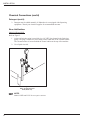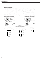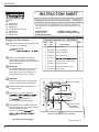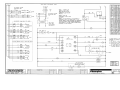
1
®
Champion
The Dishwashing Machine Specialists
Technical Manual
For machines beginning with
serial no. D2099 thru D3693
Door-Type
Dishwasher
Model
D-HBM4
High Temperature
with Built-in Booster
D-H1M4
High Temperature
D-LFM4
Low Temperature
Machine Serial No.
February, 2003
Manual P/N
P.O. Box 4149
Winston-Salem, North Carolina 27115-4149
336/661-1556
Fax: 336/661-1660
113137 Rev. C
2674 N. Service Road
Jordan Station, Ontario, Canada L0R 1S0
905/562-4195
Fax: 905/562-4618
www.championindustries.com
Complete the information below so it will be available for quick reference.
Model Number____________________________ Serial Number _________________________
Voltage and Phase _______________________________________________________________
Champion Parts Distributor ___________________________________ Phone ______________
______________________________________________________________________________
Champion Service Agency ____________________________________ Phone ______________
______________________________________________________________________________
Champion Industries Service: 1 (800) 858-4477 Champion Service Fax: 1 (336) 661-1660
In Canada:
Champion Service: 1 (800) 263-5798
Canada Service Fax: 1 (905) 562-4618
We strongly recommend that you fax your orders.
NOTE: When calling to order parts, be sure to have the model number, serial number, voltage,
and phase of your machine.
Machine Data Plate with
Model & Serial number
located on left side of
control cabinet.
COPYRIGHT © 2003 by Champion Industries, Inc.
REVISIONS
Revision History
Revision
Date
Revised
Pages
Serial Number
Effectivity
4/2/01
All
——
8/16/01
All
D2099
Issued as permanent manual
D2964
First S/N with electrical drain valve 113315
and timer 113314
8/16/01
Comments
Issue temporary manual with replacement parts lists
8/16/01
39
Added P/N 900830 Drain Valve kit
for machines S/N D2099 thru D2963
11/05/01
27
Corrected Corner Machine Side Door
1/03/02
47, 51
1/03/02
32, 33
Added straight track assembly
5/20/02
47, 51
Added 900837 Kit* Repair 3/4" Vacuum Breaker
12/18/02
55
D3857
2/5/03
27
—
Replaced P/N 108391 with 113622.
2/5/03
53
—
Replaced P/N 11143 with 113248.
2/5/03
55
—
Replaced Furnace (Siemens) overloads
with Telemecanique (Square D) overloads.
D3291
Change vacuum breaker 3/4" 104429 to 113222
Inserted timer control board kit P/N 900911
to replace 112676
i
CONTENTS
CONTENTS
Page
ii
WARRANTY .............................................................................................................................
vi
INTRODUCTION......................................................................................................................
1
GENERAL .................................................................................................................................
Model Numbers ...................................................................................................................
Standard Equipment ............................................................................................................
Options.................................................................................................................................
Accessories ..........................................................................................................................
Electrical Power Requirements ...........................................................................................
2
2
2
2
2
3
INSTALLATION........................................................................................................................
Unpacking............................................................................................................................
Changing from Straight-through to Corner Operation........................................................
Electrical Connections.........................................................................................................
Plumbing Connections.........................................................................................................
Water Connections...............................................................................................................
Drain Connections ...............................................................................................................
Chemical Connections.........................................................................................................
Model D-HB, D-H1 and D-LF .....................................................................................
Detergent..............................................................................................................................
Rinse Aid/Sanitizer..............................................................................................................
4
4
4
4
5
6
6
7
7
7
8
INITIAL START-UP ..................................................................................................................
Model D-HB, D-H1 and D-LF
10
OPERATION..............................................................................................................................
Model D-HB, D-H1 and D-LF
11
MAINTENANCE.......................................................................................................................
Maintenance Schedule.........................................................................................................
12
12
CLEANING ..................................................................................................................
Every 2 Hours or After Each Meal Period
Model D-HB, D-H1 and D-LF ........................................................................
Every 8 Hours or at the End of the Day
Model D-HB, D-H1 and D-LF ........................................................................
12
DELIMING ...................................................................................................................
Deliming process
Model D-HB, D-H1 and D-LF ........................................................................
13
OPERATION CHECKS................................................................................................
Daily .......................................................................................................................
Weekly ....................................................................................................................
14
14
14
12
12
13
CONTENTS
CONTENTS
Page
TROUBLESHOOTING .............................................................................................................
14
BASIC SERVICE.......................................................................................................................
Electrical Service .................................................................................................................
Fuses ..........................................................................................................................
Motor Overloads ...........................................................................................................
Solid State Control Board .............................................................................................
Low Water Tank Heat Protection..................................................................................
Heater Element Wiring .................................................................................................
Motor Connections........................................................................................................
Mechanical Service..............................................................................................................
Pump Seal Replacement ...............................................................................................
16
16
17
17
18
20
21
22
23
23
REPLACEMENT PARTS LIST ................................................................................................
25
ELECTRICAL SCHEMATICS .................................................................................................
65
LIST OF FIGURES
Figure 1
Figure 2
Figure 3
Figure 4
Figure 5
Figure 6
Figure 7
Figure 8
Figure 9
Figure 10
Figure 11
Figure 12
Figure 13
Figure 14
Figure 15
Figure 16
Figure 17
Figure 18
Figure 19A
Figure 19B
Figure 20
Figure 21
Figure 22
Figure 23
Figure 24
Figure 25
—
—
—
—
—
—
—
—
—
—
—
—
—
—
—
—
—
—
—
—
—
—
—
—
—
—
D-HB 3/4" NPT Water Supply Connection ......................................................
D-H1/ D-LF 3/4" NPT Water Supply Connection............................................
Chemical Connection Points.............................................................................
Wash Tank Detergent Equipment Insertion Points ..........................................
Rinse Aid Injection Point (D-HB, D-H1 Only)................................................
Rinse Aid/Sanitizer Injection Points (D-LF) ....................................................
Operator Controls..............................................................................................
Door Activated Drain Lever Assembly ............................................................
Fuses..................................................................................................................
Motor Overload.................................................................................................
Solid State Control Board .................................................................................
Float Switch ......................................................................................................
Float Switch Troubleshooting Chart .................................................................
Pump Motor Wiring Diagrams .........................................................................
Pump Seal Replacement ...................................................................................
Doors, Panels and Gauges ................................................................................
Door Guides, Stops, and Lift Bracket...............................................................
Door Handle and Spring Assembly .................................................................
Straight Track Assembly...................................................................................
Corner Track Assembly ....................................................................................
Wash/Rinse Spray Piping..................................................................................
Wash/Rinse Spray Arms ..................................................................................
Drain Assembly and Scrap Screens ..................................................................
Wash Tank Heat, Thermostats, and Float Switch .............................................
Electric Booster and Thermostat (D-HB Only) ................................................
D-HB Lower Fill Piping Assembly ..................................................................
5
5
7
7
8
9
10
10
17
17
19
20
20
22
23
26
28
30
32
32
34
36
38
40
42
44
iii
CONTENTS
LIST OF FIGURES (cont’d)
Page
Figure 26 —
Figure 27 —
Figure 28 —
Figure 29 —
Figure 30 —
Figure 31 —
D-HB, D-H1 Upper Fill Piping Assembly...........................................................
D-H1, D-LF Lower Fill Piping Assembly ...........................................................
D-LF Upper Fill Piping Assembly .......................................................................
Pump Assembly....................................................................................................
Control Cabinet ....................................................................................................
Dishracks and PRV...............................................................................................
46
48
50
52
54
56
APPENDIXES
Appendix A
Appendix B
Appendix C
Appendix D
—
—
—
—
Conversion Information ..................................................................................
Straight to Corner (Door Conversion Kit) ......................................................
Corner to Straight (Door Conversion Kit) ......................................................
Drain/Timer Circuit ........................................................................................
60
61
63
64
ELECTRIC SCHEMATICS
B701650/E — Wiring Diagram (D-HB, D-H1, D-LF Steam/Electric 1 & 3 Phase) ..............
iv
65
THIS PAGE
INTENTIONALLY
LEFT BLANK
v
WARRANTY
LIMITED WARRANTY
Champion Industries Inc. (herein referred to as Champion), P.O. Box 4149, Winston-Salem, North Carolina 27115,
and P.O. Box 301, 2674 North Service Road, Jordan Station, Ontario, Canada, L0R 1S0, warrants machines, and parts,
as set out below.
Warranty of Machines: Champion warrants all new machines of its manufacture bearing the name “Champion”
and installed within the United States and Canada to be free from defects in material and workmanship for a
period of one (1) year after the date of installation or fifteen (15) months after the date of shipment by
Champion, whichever occurs first. [See below for special provisions relating to glasswashers.] The warranty
registration card must be returned to Champion within ten (10) days after installation. If warranty card is not
returned to Champion within such period, the warranty will expire after one year from the date of shipment.
Champion will not assume any responsibility for extra costs for installation in any area where there are
jurisdictional problems with local trades or unions.
If a defect in workmanship or material is found to exist within the warranty period, Champion, at its election,
will either repair or replace the defective machine or accept return of the machine for full credit; provided,
however, as to glasswashers, Champion’s obligation with respect to labor associated with any repairs shall end
(a) 120 days after shipment, or (b) 90 days after installation, whichever occurs first. In the event that Champion
elects to repair, the labor and work to be performed in connection with the warranty shall be done during regular
working hours by a Champion authorized service technician. Defective parts become the property of Champion.
Use of replacement parts not authorized by Champion will relieve Champion of all further liability in connection
with its warranty. In no event will Champion’s warranty obligation exceed Champion’s charge for the machine.
The following are not covered by Champion’s warranty:
a.
b.
c.
d.
e.
f.
g.
h.
i.
Lighting of gas pilots or burners.
Cleaning of gas lines.
Replacement of fuses or resetting of overload breakers.
Adjustment of thermostats.
Adjustment of clutches.
Opening or closing of utility supply valves or switching of electrical supply current.
Cleaning of valves, strainers, screens, nozzles, or spray pipes.
Performance of regular maintenance and cleaning as outlined in operator’s guide.
Damages resulting from water conditions, accidents, alterations, improper use, abuse,
tampering, improper installation, or failure to follow maintenance and operation procedures.
j. Wear on Pulper cutter blocks, pulse vanes, and auger brush.
Examples of the defects not covered by warranty include, but are not limited to: (1) Damage to the exterior or
interior finish as a result of the above. (2) Use with utility service other than that designated on the rating plate.
(3) Improper connection to utility service. (4) Inadequate or excessive water pressure. (5) Corrosion from chemicals dispensed in excess of recommended concentrations. (6) Failure of electrical components due to connection
of chemical dispensing equipment installed by others. (7) Leaks or damage resulting from such leaks caused by
the installer, including those at machine table connections or by connection of chemical dispensing equipment
installed by others. (8) Failure to comply with local building codes. (9) Damage caused by labor dispute.
Warranty of Parts: Champion warrants all new machine parts produced or authorized by Champion to be free
from defects in material and workmanship for a period of 90 days from date of invoice. If any defect in
material and workmanship is found to exist within the warranty period Champion will replace the defective
part without charge.
DISCLAIMER OF WARRANTIES AND LIMITATIONS OF LIABILITY. CHAMPION’S WARRANTY
IS ONLY TO THE EXTENT REFLECTED ABOVE. CHAMPION MAKES NO OTHER WARRANTIES,
EXPRESS OR IMPLIED, INCLUDING, BUT NOT LIMITED, TO ANY WARRANTY OF
MERCHANTABILITY, OR FITNESS OF PURPOSE. CHAMPION SHALL NOT BE LIABLE FOR
INCIDENTAL OR CONSEQUENTIAL DAMAGES. THE REMEDIES SET OUT ABOVE ARE THE
EXCLUSIVE REMEDIES FOR ANY DEFECTS FOUND TO EXIST IN CHAMPION DISHWASHING
MACHINES AND CHAMPION PARTS, AND ALL OTHER REMEDIES ARE EXCLUDED, INCLUDING
ANY LIABILITY FOR INCIDENTALS OR CONSEQUENTIAL DAMAGES.
Champion does not authorize any other person, including persons who deal in Champion dishwashing machines to
change this warranty or create any other obligation in connection with Champion Dishwashing Machines.
vi
INTRODUCTION
INTRODUCTION
Welcome to Champion . . .
and thank you for allowing us to take care of your dishwashing needs.
This manual covers the door-type series dishwasher models D-H1, D-HB, and D-LF.
Your machine was completely assembled, inspected, and thoroughly tested at our factory before
it was shipped to your installation site.
This manual contains:
• Warranty Information
• Operation and Cleaning Instructions
• Maintenance Instructions
• Troubleshooting Guide
• Basic Service Information
• Replacement Parts Lists
• Electrical Schematics
Complete and return your warranty registration card within ten (10) days after the installation of
your machine.
All information, illustrations and specifications contained in this manual are based upon the
latest product information available at the time of publication. Champion constantly improves
its products and reserves the right to make changes at any time or to change specifications or
design without notice and without incurring obligation.
For your protection, factory authorized parts should always be used for repairs.
Replacement parts may be ordered from your Champion authorized parts distributor or
from your Champion authorized service agency. When ordering parts, please supply the model
number, serial number, voltage and phase of your machine, the part number, part description and
quantity.
1
GENERAL
GENERAL
This manual covers the Champion door type dishwashing machine. These machines are fully
automatic and come equipped with a 1-HP pump motor.
The D-series dishwasher is available in the following models:
Model Numbers
D-H1, D-HB, D-LF
The D-H1 model is a high temperature (180°F/82°C rinse) sanitizing model without booster.
The D-HB model is a high temperature (180°F/82°C rinse) sanitizing model with booster.
The D-LF is a low temperature (Min. 140°F/60°C) sanitizing model for use with a sodium
hypochlorite (Chlorine) based sanitizer at a minimum concentration of 50PPM in the final rinse.
Standard Equipment includes:
D-H1, D-HB, D-LF
• Automatic tank fill
• Built-in electric (D-HB only) or
steam booster heater (D-HB only)
• Drain Valve – Electric
• Specified as straight-through or corner model
• Electric tank heat
• Balanced three door lift system
• Low-water tank heat protection
• 1-Hp drip-proof pump motor
• Door safety switches
• Common utility connections
• Two dish racks (peg and flat bottom)
• Detergent/chemical connection provisions
• Stainless steel front and side panels
• Top-mounted, splash-proof control console
• 60-second time cycle
• 2" O.D. gravity drain connection
• Water pressure regulating valve
(mounted) (D-HB only)
• Interchangeable upper and lower spray arms
Options (D-HB only)
• Electric booster (70°F/39°C temperature rise)
heater for 110°F/43°C supply water
• Steam injector or steam coil tank heat
(steam booster 40°F/23°C – 70°F/39°C rise)
Accessories
Additional dishracks:
Dish rack (peg)
Silverware rack (flat bottom)
3/4” Pressure reducing valve (PRV)
2
P/N 101285
P/N 101273
P/N 112387
GENERAL
Electrical Power Requirements for Electric Heat / Electric Booster
Model
Voltage
Booster Rise
(D-HB Only)
Rated
Amps
Minimum Supply Ckt.
Conductor Ampacity
Maximum Overcurrent
Protective Device
D-H1/LF
D-H1/LF
D-H1/LF
D-H1/LF
D-H1/LF
D-H1/LF
D-H1/LF
D-H1/LF
D-H1/LF
D-H1/LF
D-H1/LF
D-H1/LF
D-H1/LF
D-HB
D-HB
D-HB
D-HB
D-HB
D-HB
D-HB
D-HB
D-HB
D-HB
D-HB
D-HB
D-HB
D-HB
D-HB
D-HB
D-HB
D-HB
D-HB
D-HB
D-HB
D-HB
D-HB
D-HB
D-HB
D-HB
115/60/1
208/60/1
220/60/1
230/60/1
240/60/1
208/60/3
220/60/3
230/60/3
240/60/3
380/60/3
415/60/3
480/60/3
575/60/3
115/60/1
208/60/1
220/60/1
230/60/1
240/60/1
208/60/3
220/60/3
230/60/3
240/60/3
380/60/3
415/60/3
480/60/3
575/60/3
115/60/1
208/60/1
220/60/1
230/60/1
240/60/1
208/60/3
220/60/3
230/60/3
240/60/3
380/60/3
415/60/3
480/60/3
575/60/3
—
—
—
—
—
—
—
—
—
—
—
—
—
—
40°F/23°C
40°F/23°C
40°F/23°C
40°F/23°C
40°F/23°C
40°F/23°C
40°F/23°C
40°F/23°C
40°F/23°C
40°F/23°C
40°F/23°C
40°F/23°C
—
—
—
—
—
70°F/39°C
70°F/39°C
70°F/39°C
70°F/39°C
70°F/39°C
70°F/39°C
70°F/39°C
70°F/39°C
49 Amps
25 Amps
26 Amps
26 Amps
26 Amps
14 Amps
14 Amps
14 Amps
15 Amps
9 Amps
9 Amps
7 Amps
6 Amps
—
69 Amps
76 Amps
76 Amps
76 Amps
39 Amps
39 Amps
43 Amps
43 Amps
24 Amps
25 Amps
18 Amps
15 Amps
—
—
—
—
—
51 Amps
51 Amps
58 Amps
58 Amps
31 Amps
34 Amps
29 Amps
24 Amps
60 Amps
35 Amps
35 Amps
35 Amps
35 Amps
20 Amps
20 Amps
20 Amps
20 Amps
15 Amps
15 Amps
15 Amps
15 Amps
—
80 Amps
80 Amps
80 Amps
90 Amps
45 Amps
45 Amps
45 Amps
50 Amps
30 Amps
30 Amps
25 Amps
20 Amps
—
—
—
—
—
70 Amps
70 Amps
70 Amps
80 Amps
40 Amps
45 Amps
35 Amps
30 Amps
60 Amps
35 Amps
35 Amps
35 Amps
35 Amps
20 Amps
20 Amps
20 Amps
20 Amps
15 Amps
15 Amps
15 Amps
15 Amps
80 Amps
80 Amps
80 Amps
90 Amps
45 Amps
45 Amps
45 Amps
50 Amps
30 Amps
30 Amps
25 Amps
20 Amps
—
—
—
—
—
70 Amps
70 Amps
70 Amps
80 Amps
40 Amps
45 Amps
35 Amps
30 Amps
Electrical Power Requirements for Steam or Gas Heat /
Steam or Gas Booster
Model
Voltage
Booster Rise
(D-HB Only)
Rated
Amps
Minimum Supply Ckt.
Conductor Ampacity
Maximum Overcurrent
Protective Device
D-H1/LF
D-H1/LF
D-H1/LF
D-H1/LF
D-H1/LF
D-H1/LF
D-H1/LF
D-H1/LF
D-H1/LF
D-H1/LF
D-H1/LF
D-H1/LF
D-H1/LF
D-HB
D-HB
D-HB
D-HB
D-HB
D-HB
D-HB
D-HB
D-HB
D-HB
D-HB
D-HB
D-HB
D-HB
D-HB
D-HB
D-HB
D-HB
D-HB
D-HB
D-HB
D-HB
D-HB
D-HB
D-HB
D-HB
115/60/1
208/60/1
220/60/1
230/60/1
240/60/1
208/60/3
220/60/3
230/60/3
240/60/3
380/60/3
415/60/3
480/60/3
575/60/3
115/60/1
208/60/1
220/60/1
230/60/1
240/60/1
208/60/3
220/60/3
230/60/3
240/60/3
380/60/3
415/60/3
480/60/3
575/60/3
115/60/1
208/60/1
220/60/1
230/60/1
240/60/1
208/60/3
220/60/3
230/60/3
240/60/3
380/60/3
415/60/3
480/60/3
575/60/3
—
—
—
—
—
—
—
—
—
—
—
—
—
—
40°F/23°C
40°F/23°C
40°F/23°C
40°F/23°C
40°F/23°C
40°F/23°C
40°F/23°C
40°F/23°C
40°F/23°C
40°F/23°C
40°F/23°C
40°F/23°C
—
—
—
—
—
70°F/39°C
70°F/39°C
70°F/39°C
70°F/39°C
70°F/39°C
70°F/39°C
70°F/39°C
70°F/39°C
22 Amps
13 Amps
13 Amps
13 Amps
11 Amps
6 Amps
6 Amps
6 Amps
6 Amps
4 Amps
4 Amps
3 Amps
3 Amps
—
22 Amps
13 Amps
13 Amps
13 Amps
6 Amps
6 Amps
6 Amps
6 Amps
4 Amps
4 Amps
3 Amps
3 Amps
—
—
—
—
—
6 Amps
6 Amps
6 Amps
6 Amps
4 Amps
4 Amps
3 Amps
3 Amps
30 Amps
15 Amps
15 Amps
15 Amps
15 Amps
15 Amps
15 Amps
15 Amps
15 Amps
15 Amps
15 Amps
15 Amps
15 Amps
—
30 Amps
15 Amps
15 Amps
15 Amps
15 Amps
15 Amps
15 Amps
15 Amps
15 Amps
15 Amps
15 Amps
15 Amps
—
—
—
—
—
15 Amps
15 Amps
15 Amps
15 Amps
15 Amps
15 Amps
15 Amps
15 Amps
30 Amps
15 Amps
15 Amps
15 Amps
15 Amps
15 Amps
15 Amps
15 Amps
15 Amps
15 Amps
15 Amps
15 Amps
15 Amps
30 Amps
15 Amps
15 Amps
15 Amps
15 Amps
15 Amps
15 Amps
15 Amps
15 Amps
15 Amps
15 Amps
15 Amps
—
—
—
—
—
15 Amps
15 Amps
15 Amps
15 Amps
15 Amps
15 Amps
15 Amps
15 Amps
3
INSTALLATION
INSTALLATION
Unpacking
!
CAUTION:
Care should be taken when lifting the machine to prevent damage.
1. Immediately after unpacking the machine, inspect for any shipping damage. If damage
is found, save the packing material and contact the carrier immediately.
2. Remove the dishwasher from the skid. Adjust the feet if required, then move the
machine to its permanent location.
3. Level the machine (if required) by placing a level on the top of machine and adjusting
the feet. Level the machine front-to-back and side-to-side.
4. Remove the two dishracks and pressure gauge from the interior of the machine. Install
the pressure gauge in the upper fill piping of the dishwasher in the petcock provided.
NOTE:
The installation of your machine must meet local health codes.
Changing from Straight-through to Corner Operation
Your door-type dishwasher was specified to the factory as a straight-through configuration or
corner configuration. Your machine can be converted from straight-through to corner or from
corner to straight-through. The factory has kits for these conversions available. For instructions
and part numbers, see Appendixes A, B, and C.
Electrical Connections
!
!
WARNING:
Electrical and grounding connections must comply with the National Electrical Code
and/or Local Electrical Codes.
WARNING:
When working on the dishwasher, disconnect the electric service and place a tag at the
disconnect switch to indicate work is being done on that circuit.
1. A qualified electrician must compare the electrical power supply with the machine
electrical specifications stamped on the MACHINE ELECTRICAL CONNECTION
PLATE located inside the top mounted control cabinet before connecting to the
incoming service at a fused disconnect switch.
2. Motor rotation was set at the factory. Check the rotation of the motor shaft (CW when
viewed from rear of motor). For three phase machines, reversing the motor direction is
done in the control cabinet by reversing the wires L1 and L2 on the disconnect side of
4
INSTALLATION
Electrical Connections (cont’d)
the main electrical connection block. For single phase machines, motor rotation is
changed at the motor connection plate on the rear of the single phase motor.
3. A knock-out is provided at the rear of the top mounted control cabinet for the electrical
service connection. A single source electrical connection has been provided. A fused
disconnect switch or circuit breaker (supplied by others) is required to protect each
power supply circuit.
Plumbing Connections
!
CAUTION:
Plumbing connections must comply with local sanitary and plumbing codes.
Water Connections
1. Connect the hot water supply using a 3/4” NPT connection. The connection point is
located behind the lower front panel of the dishwasher. Supply enters from underneath
the machine.
8-7/8"
[225 mm]
8-7/8"
[225 mm]
R
OO
OR
FLO
Figure 1
D-HB
3/4” NPT Water Supply Connection
Behind Front Panel
FL
Figure 2
D-H1, D-LF
3/4” NPT Water Supply Connection
Behind Front Panel
2. Minimum incoming water supply temperature requirements are listed below:
D-HB with built-in 40°F/23°C rise electric booster (Minimum 140°F/60°C)
(Min./Max. flow pressure 20 – 22 psi/138 Kpa)
D-HB with built-in 70°F/39°C rise electric booster (Minimum 110°F/43°C)
(Min./Max. flow pressure 20 – 22 psi/138 Kpa)
D-H1 without built-in booster (Minimum 180°F/70°C)
(Min./Max. flow pressure 20 – 22 psi/138 Kpa)
D-LF (Minimum 140°F/60°C)
(Min./Max. flow pressure 20 – 22 psi/138 Kpa)
5
INSTALLATION
Water Connections (cont’d)
3. A manual shut-off valve for steam and water (supplied by others) should be installed in
supply line to allow for servicing of the machine. The shut-off valve should be the same
size or larger than the supply line.
4. A 3/4" Pressure Regulating Valve (PRV), should be installed on the incoming water
supply line if water flow pressure exceeds 20 – 22 psi/138 Kpa.
A PRV is standard equipment on Model D-HB.
A PRV is not standard equipment on Models D-H1 and D-LF.
The PRV may be obtained locally or direct from Champion.
Drain Connections
1. Models D-HB, D-H1, and D-LF are GRAVITY DRAIN machines equipped with a
2" hose connection point.
• Drain height for ALL MODELS must not exceed 8-7/8" [225 mm] above floor level.
!
WARNING:
Connection of the machine to a drain line higher than the machine drain height will
prevent the machine from draining properly.
Ventilation
NOTE:
Ventilation must comply with local sanitary and plumbing codes.
!
6
CAUTION:
Exhaust air should not be vented into a wall, ceiling, or concealed space of a building.
Condensation can cause damage.
INSTALLATION
Chemical Connections
NOTE:
Consult a qualified chemical supplier for your chemical needs.
Models D-HB, D-H1 and D-LF
Refer to Figure 3.
1. Labeled chemical signal connection points are provided inside the control cabinet for
chemical dispensing equipment (supplied by others).
5
6
12
17
18
19
CAUTION
RINSE/SANI
120V SUPPLY COMMON
DISPENSERS RETURN
ONLY
DETERGENT
15
2
2
10
Signal connection points include:
• Detergent signal 120VAC
between Wire #10 and Wire #2
(1 AMP MAX AMP LOAD)
• Rinse Aid/Sanitizer signal 120VAC
between Wire #15 and Wire #2
(1 AMP MAX AMP LOAD)
Figure 3
D-HB, D-H1, D-LF
Chemical Connection Points
Left Side Interior of Control Cabinet
Detergent
Refer to Figure 4.
1. Two removable black plugs, located on the rear and left side of the wash tank are
provided as detergent equipment insertion points.
1/2" Black Removable Plug
Detergent Injection Point
Figure 4
D-HB, D-H1, D-LF
Wash Tank Detergent Equipment
Insertion Points
1/2" Black Removable Plug
Detergent Sensor Point
7
INSTALLATION
Chemical Connections (cont’d)
Detergent (cont’d)
2. Detergent may be added manually if dishwasher is not equipped with dispensing
equipment. Consult your chemical supplier for recommended amounts.
Rinse Aid/Sanitizer
Model D-HB and D-H1
Refer to Figure 5.
1. A rinse aid injection point is provided via a 1/4" NPT plug located in the final rinse
piping. The plug is located in a cross fitting on the outlet side of the vacuum breaker.
The vacuum breaker is located behind the control cabinet at the top of the machine.
2. Use a liquid rinse aid.
Figure 5
Rinse Aid Injection Point
D-HB, D-H1 Only
NOTE:
Models D-HB and D-H1 do not require sanitizer.
8
INSTALLATION
Chemical Connections (cont’d)
Rinse Aid/Sanitizer (cont’d)
Model D-LF
Refer to Figure 6.
1. A rinse aid injection point is provided via a 1/4" NPT plug located in the final rinse
piping. The plug is located in a cross fitting on the outlet side of the vacuum breaker.
The vacuum breaker is located behind the control cabinet at the top of the machine.
2. Use a liquid rinse aid.
3. A sanitizer injection point is provided via a 1/8" NPT plug located in the final rinse
piping. The plug is located in a cross fitting on the outlet side of the vacuum breaker.
The vacuum breaker is located behind the control cabinet at the top of the machine.
4. Use a sodium hypochlorite (Chlorine) based sanitizer at a minimum concentration of
50PPM in the final rinse. Use chlorine test papers to verify and monitor the 50PPM
chlorine level.
Figure 6
D-LF
Rinse Aid/Sanitizer Injection Points
!
WARNING:
Never premix rinse aid with the sanitizing agent. Mixing may cause hazardous gases
to form.
!
CAUTION:
Some metal, including silver, aluminum, and pewter are attacked by sodium
hypochlorite (chlorine sanitizer). Avoid cleaning these metals in a D-LF dishwasher.
9
INITIAL START-UP
INITIAL START-UP
After plumbing and electrical connections are completed, follow the steps below to place your
machine in service.
Model D-HB, D-H1 and D-LF
Refer to Figures 7 and 8 below.
1. Remove any foreign material from inside the machine. Make sure scrap screens are in
place.
2. Make sure wash and rinse arms are installed correctly.
3. Close the Door.
4. Turn the water and main power sources to the dishwasher ON.
5. Flip the Power switch to the ON position. The “power on” light will illuminate and the
machine will automatically fill with water.
6. Check the machine for leaks.
7. Push the Green Start Button to check automatic cycle.
8. Check pump motor rotation. Rotation is CW when viewed from rear of motor.
9. If machine checks okay, flip the power switch to OFF and machine will drain for
ten minutes.
Main power switch
circuit breaker
Pressure gauge
Green pushbutton
start switch
POWER
Champion
WASH
START
RINSE
IN
CYCLE
ON
OFF
WA R N I N G !
Green in cycle lite
TURN OFF POWER BEFORE
S E RV I C I N G M AC H I N E
Figure 7
Operator Controls
Top Mounted Control Cabinet
Temperature Gauges
POWER
ON
OFF
Figure 8
Drain Assembly
10
OPERATION
OPERATION
Model D-HB, D-H1 and D-LF
1. Close the door and flip power switch ON
Power light illuminates. Drain valve closes.
Tank fills automatically and tank heat
comes on.
2. Monitor wash tank temperature gauge
Wait for temperature reading to reach
Min. 150°F/66°C (D-HB, D-H1 Only)
Temperature reading must be
Min. 120°F-140°F/49°C-60°C Optimum
(For D-LF Only)
3. Prescrap and load ware into rack
Place dishes edgewise in peg rack, cups and
bowls upside down in flat rack, and
silverware spread evenly in single layer in
flat rack.
4. Open door, insert rack
5. Close door, Push Green start button
Green cycle light will illuminate. Automatic
cycle begins.
Machine washes for 45 sec., then pauses for
1 sec.
6. During Final Rinse monitor pressure
Machine final rinses for 14 sec. Pressure
gauge and final rinse temperature gauge
reading must read between 20 – 22 PSI.
Temperature gauge must read
180 – 195°F/82 – 91°C (D-HB, D-H1 Only)
Min. 120° – 140°F/49°C – 60°C Optimum
(D-LF Only)
7. 60-second cycle complete
Green cycle light goes out.
8. Open door, remove clean rack
Insert another rack of soiled ware.
9. After each meal period or every two
hours operation
Turn power switch to OFF position and
machine will drain for ten minutes. Flush
interior and clean scrap screens and pump
intake strainer. Check spray arms and clean
if necessary. Flip power switch ON and OFF
to drain remaining water repeat as necessary.
NOTE:
Opening the door at any time during the cycle will stop the machine.
Closing the door and pushing the Green start button will resume the cycle where it
left off.
11
MAINTENANCE
MAINTENANCE
Cleaning your machine is the best maintenance that you can provide. Components that are not
regularly flushed and cleaned do not perform well.
The Maintenance intervals shown in the following schedules are the minimum requirements
necessary for the proper performance of your machine. Maintenance intervals should be
shortened whenever your machine is faced with abnormal working conditions, hard water, or
multiple shift operations.
Maintenance Schedule
CLEANING
• Every 2 Hours or After Each Meal Period
Model D-HB, D-H1, and D-LF
1. Flip the power switch OFF.
2. Machine drain valve will open for 10 minutes automatically.
3. Flush tank interior with fresh water.
4. Remove and clean the scrap screens. Clean the pump intake screen.
5. Inspect the spray arm nozzles and rinse nozzles. Clean if necessary.
6. Close door, flip power switch ON to refill machine.
• Every 8 Hours or at the End of the Day
Model D-HB, D-H1, and D-LF
1. Flip the power switch OFF.
2. Machine drain valve will open for 10 minutes automatically.
3. Flush tank interior with fresh water.
4. Remove and clean the scrap screens. Clean the pump intake screen.
5. Remove the spray arms.
6. Clean and inspect the spray arm bearings.
7. Flush the wash arm and rinse arm assemblies and nozzles.
8. Back flush the scrap screens and pump intake strainer.
9. Flip power switch ON then OFF to open drain valve for 10 minutes.
10. Reassemble the machine. Leave the door open to aid overnight drying.
!
12
CAUTION:
DO NOT LEAVE WATER IN WASH TANK OVERNIGHT
MAINTENANCE
DELIMING
Your dishwasher should be delimed regularly depending on the mineral content of your water.
Inspect the machine interior for mineral deposits and use a deliming solution for the best
cleaning results.
NOTE:
Consult your chemical supplier for an appropriate deliming solution.
!
WARNING:
Deliming solutions or other acids must not come in contact with household bleach
(sodium hypochlorite) or any chemicals containing chlorine, iodine, bromine, or
fluorine. Mixing will cause hazardous gases to form.
Skin contact with deliming solutions can cause severe irritation and possible chemical
burns. Consult your chemical supplier for specific safety precautions.
DELIMING PROCESS
Model D-HB, D-H1, and D-LF
1. Remove all dishes from machine.
2. Remove any chemical pick-up tubes from their containers.
3. Place each tube in a container of fresh water and prime the chemical lines for several
minutes to thoroughly flush chemical from the lines. Leave pick-up tubes out of their
containers.
4. Turn power switch to OFF position to drain machine for ten minutes, return power
switch to ON position to refill with fresh water.
5. Spray interior walls with delimimg solution and let sit for 5 or 10 minutes depending on
amount of build-up. Add deliming solution to wash tank. Do not let chemicals sit for
longer than 15 minutes.
6. Push the Green start button and run an automatic cycle.
7. Repeat Steps 3-4 if necessary.
8. Repeat Step 4.
9. Refill the machine and run a complete cycle two additional times. Drain and refill the
machine after each cycle to thoroughly flush any deliming solution from the interior of
the machine.
10. Flip the power switch to OFF.
11. Machine drain valve will open for 10 minutes to drain machine completely.
12. Deliming is complete.
13
MAINTENANCE
OPERATION CHECKS
• Daily
1. Check temperature gauges for proper readings.
2. Check pressure gauge for proper reading (D-H1, D-HB ONLY).
3. Check for leaks.
4. Check chemical supplies and refill as necessary.
• Weekly
1. Inspect all water lines for leaks.
2. Clean all detergent residue from the exterior of the machine.
3. Check the drains for leaks.
4. Clean accumulated mineral deposits from the tank heating elements
5. Check that float switch moves freely.
TROUBLESHOOTING
Before determining any specific cause of a breakdown or abnormal operation on your
dishwasher, check that:
Checklist
1. Main power and water supply are turned on to the machine
2. All switches are ON
3. Wash pipe and rinse nozzles are clean
4. Scrap screen(s) are properly positioned
5. Spray pipes are in their proper positions
6. Doors are fully closed
7. Thermostat(s) are at their correct setting
8. Sanitizer, detergent, and rinse additive dispensers are adequately filled.
9. Drain valve/timer problems see Appendix D for trouble shooting.
If a problem still exists, use the following for troubleshooting.
14
TROUBLESHOOTING
CONDITION
Machine will not start
CAUSE
Door not closed . . . . . . . . . . . . . . . . .
Door safety switch faulty . . . . . . . . . .
Start switch faulty . . . . . . . . . . . . . . .
Main switch OFF . . . . . . . . . . . . . . . .
Overload protector tripped . . . . . . . . .
Low or no water
Main water supply is turned off . . . . .
Faulty drain valve . . . . . . . . . . . . . . . .
Machine doors not fully closed . . . . .
Faulty fill valve . . . . . . . . . . . . . . . . .
Defective circuit board . . . . . . . . . . . .
Stuck or defective float . . . . . . . . . . .
Clogged “Y” strainer . . . . . . . . . . . . .
Continuous water filling
Stuck or defective float . . . . . . . . . . .
Drain valve will not close . . . . . . . . .
Fill valve will not close . . . . . . . . . . .
Defective circuit board . . . . . . . . . . . .
Any motor not running
Overload protector tripped . . . . . . . . .
Defective motor . . . . . . . . . . . . . . . . .
Wash tank water
Incoming water temperature
temperature is low
at machine too low . . . . . . . . . . . . . .
when in use
..............................
..............................
Defective thermometer . . . . . . . . . . . .
Defective thermostat . . . . . . . . . . . . .
Lime scale buildup
on heating elements . . . . . . . . . . . . .
Defective heater element . . . . . . . . . .
Low steam pressure . . . . . . . . . . . . . .
Defective steam trap . . . . . . . . . . . . . .
Defective solenoid valve . . . . . . . . . .
Insufficient pumped
Clogged pump intake screen . . . . . . .
spray pressure
Clogged spray pipe . . . . . . . . . . . . . . .
Scrap screen full . . . . . . . . . . . . . . . . .
Low water level in tank . . . . . . . . . . .
Pump motor rotation incorrect . . . . . .
..............................
Defective pump seal . . . . . . . . . . . . . .
Insufficient final rinse or
Faulty pressure reducing valve . . . . .
no final rinse
Improper setting on pressure
reducing valve . . . . . . . . . . . . . . . . .
Clogged rinse nozzle and/or pipe . . . .
Improper water line size . . . . . . . . . . .
Clogged “Y” strainer . . . . . . . . . . . . .
Low final rinse temperature Low incoming water temperature . . .
Improper setting of booster
thermostat . . . . . . . . . . . . . . . . . . . . .
..............................
Defective booster thermostat . . . . . . .
Defective thermometer . . . . . . . . . . . .
Poor washing results
Detergent dispenser not
operating properly . . . . . . . . . . . . . .
Insufficient detergents . . . . . . . . . . . .
Wash water temperature
too low . . . . . . . . . . . . . . . . . . . . . . .
..............................
Wash arm clogged . . . . . . . . . . . . . . .
Improperly scraped dishes . . . . . . . . .
Ware being improperly placed
in rack . . . . . . . . . . . . . . . . . . . . . . . .
Improperly cleaned equipment . . . . . .
..............................
...............................
Electric Elements or steam
coils has soil/lime buildup . . . . . . . .
Poor drying results
Insufficient rinse-aid . . . . . . . . . . . . .
Low final rinse temp . . . . . . . . . . . . .
..............................
SOLUTION
Make sure doors are fully closed
Contact your service agency
Contact your service agency
Check disconnect
Reset overload in control box
Turn on house water supply
Contact your service agency
Close doors securely
Contact your service agency
Contact your service agency
Check floats and clean
Clean or replace
Check floats and clean
Replace drain valve/Contact your service agency
Clean or replace
Contact your service agency
Reset overload in control box
Contact your service agency
Raise temperature to:
140°F/60°C for D-HB and D-LF,
180°F/82°C for D-H1
Check or replace
Check for proper setting or replace
Delime element
Check or replace
Check steam supply pressure (15 – 30 psi)
Check or replace
Check or replace
Clean
Clean
Must be kept clean and in place
Check drain
Reverse connection between L1 and L2
in Control Cabinet (3PH machines only)
Contact Service Agent
Clean or replace
Set psi flow pressure at 20 – 22 psi/138 Kpa
Clean
Have installer change to proper size (3/4" min.)
Clean or replace
Check house supply water temperature
Be sure booster thermostat is set to maintain
180°F/82°C temperature
Replace thermostat
Check for proper setting or replace
Contact detergent supplier
Contact detergent supplier
See condition “Wash tank water temperature”
above.
Clean
Check scraping procedures
Use proper racks. Do not overload racks
Unclog wash sprays and rinse nozzles to
maintain proper pressure and flow conditions.
Keep wash water as clean as possible.
Clean and/or delime
Contact chemical supplier
See condition “Low final rinse temperature”
above.
15
BASIC SERVICE
BASIC SERVICE
This Basic Service section does not cover all possible repair procedures. If you require
additional service support, you may call your local service company or:
Champion National Service
1-800-858-4477
In Canada
1-800-263-5798
Please have the Model and Serial Number of the machine ready when you call.
ELECTRICAL SERVICE
!
WARNING:
Disconnect Power at main disconnect switch before removing lower panels. Removing
lower panels exposes live open electrical wiring (not contained in conduit).
Always replace panels after completing service or repairs. Do not operate the
dishwasher with panels removed for anything other than service repair operation.
NOTE:
DO NOT USE CHASSIS GROUND WHEN PERFORMING VOLTAGE CHECKS.
Doing so will result in false and inaccurate readings.
PERFORM VOLTAGE CHECKS BY READING FROM THE HOT SIDE OF
THE LINE AND NEUTRAL (any #2 or white wire).
!
WARNING:
USE EXTREME CAUTION when performing tests on energized circuits.
!
WARNING:
When repairing a circuit, disconnect the power at the main service disconnect switch
and place a tag at the disconnect switch to indicate that work is being performed on the
circuit.
Troubleshooting
Schematics
Champion places an electrical schematic in the control cabinet of every machine before it is
shipped. Schematics are included at the back of this manual as well. Be aware that these
schematics include options that may not apply to your machine. Options are enclosed in dashed
lines with the words (IF USED) next to them on the schematic. Disregard any options that
appear on the schematics which are not a part of your machine.
16
BASIC SERVICE
Fuses
Refer to Figure 9.
There are two fuse blocks, located in the center of
the main control cabinet. The (A) fuses protect the
main control transformer. The (B) fuses protect the
wash tank heater circuit. Fuses are marked FU on the
electrical schematic. Booster heater circuits
(D-HB only) are not fused.
To Replace a fuse:
Turn the dishwasher main power switch off.
Disconnect power to the machine at the main
service disconnect switch.
Replace the fuse. If the fuse blows again,
DO NOT INCREASE THE FUSE SIZE.
DETERMINE THE CAUSE OF THE OVERLOAD.
B
A
Figure 9
Fuses
(Three phase shown)
Motor Overloads
The wash pump motor has an overload to protect it from line voltage electrical overloads.
The overload disconnects 120VAC power to the motor contactor coil.
Refer to Figure 10.
Note the Switch Lever on the Overload.
If the switch lever is off with the “0” showing then the overload has tripped.
To Reset the Motor Overload:
Flip the overload switch to the On position. A “1” should be
visible on the switch lever.
Switch Lever
To Replace a Motor Overload:
Disconnect the wires to the overload. Release the mounting
catch on the front side of the overload. Push forward and lift
out. Snap the new overload into place and reconnect the
wires.
To adjust the overload setting:
The screwdriver in Figure 10 is positioned to adjust the motor
overload AMP setting. Read the full load amps (FLA) motor
amps on the motor nameplate. Turn setting to match
nameplate.
Solid State D-HB, D-H1, and D-LF
Operating Instructions
Figure 10
Motor Overload
Automatic Operation
1.
2.
3.
4.
Check that drain is closed and screens are in place.
Turn on main power to the machine.
Flip machine control panel power switch to ON.
Close doors.*
*Machine pauses 4 seconds to check water level.
5. Machine fills for 110 seconds if float is down.
17
BASIC SERVICE
ELECTRICAL SERVICE (cont’d)
6.
7.
8.
9.
Run machine through several cycles or wait 10 minutes for temperature to stabilize.
Open door, insert rack of dishes.
Close doors. Push the GREEN push button to start cycle.
Machine cycle is:
WASH = 45 seconds
DWELL = 1 second
RINSE = 14 seconds
10. Open door, remove clean rack of dishes.
11. Repeat for additional racks.
Troubleshooting Timer Circuit Board
1.1 Introduction
The following procedures are for determining whether or not the timer circuit board itself
is faulty.
In this part —
• Checking the general condition of the circuit board.
• Testing inputs.
• Testing outputs.
Special Tools —
• A voltmeter capable of reading DC and AC volts.
1.2 Checking General Condition
Before testing the inputs and outputs, you should first check that the board is receiving power.
Turn on the power switch to the unit (do not start the unit, just turn ON power to the unit). If
red “POWER” LED on board is illuminated, go directly to “1.3 Testing Board Inputs.” When
LED is not illuminated, then check that the following conditions are true:
Power Terminals
• Verify that the board is receiving power of 120 VAC at the terminals:
— T2, marked “H” (AC Hot).
— T1, marked “N” (AC Neutral).
If either of these terminals is not receiving 120 VAC, then there is a problem elsewhere with
the unit not receiving power.
The Fuse (F1)
• Verify that the circuit board fuse (F1) is good.
If not replace it.
Red “POWER” LED
• Verify that the red “POWER” LED is illuminated.
If it is not, and the previous two conditions are true, then the board is bad and should
be replaced.
1.3 Testing Board Inputs
After you have verified that the circuit board is receiving power (as
explained above), then test the board inputs. There are 4 board inputs:
• Start Switch
• Door Safety Switch
• Float Switch
• Extended Wash (not used on this Model)
Perform the following steps to test a board input:
1. Set the voltmeter to measure DC volts.
18
BASIC SERVICE
2. Place the NEGATIVE (Black) test probe on the “HOT” terminal:
• T2, marked “H”.
3. Place the POSITIVE (Red) test probe on the input terminal to be tested:
• T7, marked “START SW” (for the Start Switch).
• T8, marked “DOOR SW” (for the Door Safety Switch).
• T9, marked “FLOAT SW” (for the Float Switch).
4. Check the results on the voltmeter:
• If switch is opened – the meter should read between 4.7 to 5.3 DC volts.
• If switch is closed – the meter should read between 0 to 1 DC volts.
1.4 Testing Board Outputs
After you have verified that the circuit board is receiving power (as explained above), then test
the board outputs. There are 4 board outputs:
• Wash Cycle
• Rinse Cycle
• Heaters
• In-Cycle Lamp
Perform the following steps to test a board output:
1. Set the voltmeter to measure AC volts.
2. Place the NEGATIVE (Black) test probe on the “NEUTRAL” terminal:
• T1, marked “N”.
3. Place the POSITIVE (Red) test probe on the output terminal to be tested:
• T3, marked “WASH OUTPUT” (for the Wash Cycle).
• T4, marked “RINSE OUTPUT” (for the Rinse Cycle).
• T5, marked “HEATERS OUTPUT” (for the Water Heater).
• T6, marked “LAMP OUTPUT” (for the In-Cycle Lamp indicator).
4. Check the results on the voltmeter for the terminal you are testing:
• For T3 – the meter should read 120 VAC whenever the unit is in cycle and the
“WASH” LED is illuminated on the circuit board.
• For T4 – the meter should read 120 VAC whenever the unit is in a fill or rinse mode and
the corresponding “FILL” or “RINSE” LED is illuminated on the circuit board.
• For T5 – the meter should read 120 VAC whenever the power switch is on and the wash
tank is full (i.e., the float switch is up).
• For T6 – the meter should read 120 VAC whenever the machine is in cycle.
F1
H
WASH
OUTPUT
T2
N
T3
T1
RINSE
OUTPUT
POWER
START SW.
T4
L1
T7
DOOR SW.
JB1
JB3
T8
FLOAT SW.
HEATERS
OUTPUT
T5
T9
EXT. WASH
L2
L3
U1
L4
FILL
RINSE
WASH
T10
LAMP
OUTPUT
T6
JB2
Figure 11
Solid State Control Board
19
BASIC SERVICE
Models D-HB, D-H1, and D-LF use a float switch and circuit board to control tank fill and tank
heat.
For Model D-HB only, the built-in booster heat circuit is also
controlled by the float switch.
Operation:
1. When dishwasher main power switch is turned on (wash
tank empty), the drain valve closes allowing cycle time to
run for a minimum of 110 seconds to fill the tank.
2. The float switch ball rises; its normally open contacts close.
The fill circuit times out; the fill solenoid de-energizes, and
the tank heat and booster heat energize.
3. If water level drops below the float level, the float switch
Figure 12
ball moves down; heat de-energizes. The fill solenoid
Float
Switch
energizes and the fill cycle runs for a minimum of 110
seconds to refill the tank.
4. If the tank is not full of water at the end of the 110-second fill cycle , then the machine
will cycle again. When the float switch is satisfied, the fill cycle stops after completing
its 110-second cycle.
5. Refer to the float switch troubleshooting chart (Fig.13) below, for a quick guide to
evaluating float switch problems.
Wash
Tank Fills Constantly
Is Tank Full
of Water?
NO
Check
Drain
NO
Clean
Float
Assy
NO
Replace
Float
YES
Is the Float
Ball Up?
YES
Is Heat ON
when called
for?
YES
Check
Solenoid
Valve
System
Checks
20
Figure 13
Float Switch
Troubleshooting Chart
BASIC SERVICE
Heater Element Wiring – Booster Tank and Wash Tank Heater Elements
Refer to the illustrations and follow the steps below to properly install terminal jumpers and to
make line power connections to a replacement element.
Step 1. Hold the element assembly with the calrod coils facing toward you.
Step 2. Match your element coil to Configuration A, B, C, or D.
Step 3. Rotate your element coils to match the correct configuration.
Step 4. Turn the element over and match your element to the correct terminal configuration.
Step 5. Install terminal jumpers according to the illustration for your voltage requirement.
Step 6. Install the element and make your line connections 1L1, 1L2, or 1L3 per the illustration.
Configuration A
Booster tank element
View of calrod coils
Terminal Connections view of element
1L3
1L1
1L3
1L3
1L1
1L2
1L1
1L1
1L2
1L2
208V/1 Phase
1L2
208-240V/3 Phase
Delta Connection
Configuration B
Booster tank element
View of calrod coils
480V/3 Phase
575V/3 Phase
Delta Connection
Terminal Connections view of element
1L1
1L1
1L1
1L2
1L2
1L3
1L1
1L2
1L3
208V/1 Phase
Configuration C
Booster tank element
View of calrod coils
208-240V/3 Phase
Wye Connection for
380-415V/3 Phase
1L3
208-240V/3 Phase
Delta Connection
1L2
480V/3 Phase
575V/3 Phase
Delta Connection
208-240V/3 Phase
Wye Connection for
380-415V/3 Phase
Terminal Connections view of element
1L2
1L1
1L1
1L1
1L3
1L2
1L2
208-240V/3 Phase
Delta Connection
480V/3 Phase
575V/3 Phase
Delta Connection
1L2
208V/1 Phase
1L3
Configuration D
Wash tank element
View of calrod coils
1L1
1L3
208-240V/3 Phase
Wye Connection for
380-415V/3 Phase
Terminal Connections view of element
1L1
1L1
1L1
1L1
1L2
1L3
1L3
1L2
208V/1 Phase
1L2
208-240V/3 Phase
Delta Connection
1L2
480V/3 Phase
575V/3 Phase
Delta Connection
1L3
208-240V/3 Phase
Wye Connection for
380-415V/3 Phase
21
BASIC SERVICE
Motor Connections
1. Models D-HB, D-H1, and D-LF are available in either single phase or 3 phase voltages.
2. Motor rotation was set at the factory. For three phase machines, reversing the motor
direction is done in the control cabinet by reversing the wires L1 and L2 on the
disconnect side of the main electrical connection block. For single phase machines,
motor rotation is changed at the motor connection plate on the rear of the single phase
motor (if necessary).
Refer to Figure 14 for the proper wiring of the pump motor for single and three phase voltages.
Single Phase - High Voltage
Single Phase - Low Voltage
LINE
L1
J
3
8
4
LINE
L1
J
3
115V
4
8
2
208-240V
LINE
LINE
2
L2
L2
Figure 14
Pump Motor Wiring Diagrams
208-240V
Three Phase - Low Voltage
6
5
4
6
5
4
9
8
7
9
8
7
3
2
1
3
2
1
LINE
22
480V
Three Phase - High Voltage
LINE
575V Only
Three Phase
3
2
LINE
1
REPLACEMENT PARTS
MECHANICAL SERVICE
Pump Seal Replacement
1.
2.
3.
4.
5.
6.
7.
8.
9.
10.
11.
12.
13.
14.
15.
16.
17.
18.
19.
Disconnect the power to the machine at the main breaker panel or fuse box.
Drain the machine.
Remove the front and side panels.
Remove drain plug on the pump volute and drain the pump.
Remove the pump hoses.
Disconnect the wires to the motor at the motor junction box.
Unbolt motor from machine base and remove the pump/motor assembly.
Remove bolts on volute and carefully remove from the pump flange.
Lock the motor shaft with a wrench or pliers. The back of motor shaft is square.
Turn the impeller counter-clockwise to remove from shaft (right hand threads).
Remove the old seal and discard.
Check seal seat in the pump flange and clean thoroughly.
Press rubber seal/ceramic portion of seal assembly into the pump flange. Use a water
soluble lubricant. Be careful to keep the ceramic clean.
Install the rotating part of the seal on the shaft with the graphite surface toward the
ceramic. Use a water soluble lubricant on the rubber seal part only (not the graphite).
Reinstall impeller and new flange gasket. Reinstall bolts.
Reinstall the pump/motor assembly and reconnect the pump hoses.
Fill the dishwasher with water.
Check motor rotation by bump starting motor. Correct motor shaft rotation is clockwise
when viewing motor from the rear.
Test run and check for leaks.
Gaskets
Pump Flange
Impeller
Volute
Washer
Seal Assy.
Bolt
(B)
Water
Slinger
Nut
Backing Plate
Mtg. Nut
Backing Plate
Bolt
(A)
Plug
Figure 15
Pump Seal Replacement
23
THIS PAGE
INTENTIONALLY
LEFT BLANK
24
REPLACEMENT PARTS
REPLACEMENT
PARTS
25
REPLACEMENT PARTS
18
19
20
13
22 21
16
17
15
24
23
12
14
11
1
13
10
2
7
3
8
9
4
4
9
4
6
26
5
7
8
25
26
Figure 16 – D-HB/D-H1/D-LF
Doors, Panels and Gauges
26
26
REPLACEMENT PARTS
D-HB/D-H1/D-LF
DOORS, PANELS AND GAUGES
Fig. 16
Item No.
1
1
2
3
4
5
6
7
8
9
10
11
12
13
14
15
16
17
17
18
19
19
20
21
22
23
24
25
26
27
28
29
30
Part
No.
Part Description
325405
325407
325408
321929
100779
321932
321941
108418
109034
108417
325406
324801
108954
100007
0508752
0508668
113622
112090
112092
107440
112086
112093
305404
107367
107368
100135
109765
112587
0504822
325392
325400-1
325400-2
325444
Side Door, Right . . . . . . . . . . . . . . . . . . . . . . . . . . . . . . . . . . . . . . .
Side Door, Right (Corner Machine) . . . . . . . . . . . . . . . . . . . . . . . .
Front Door . . . . . . . . . . . . . . . . . . . . . . . . . . . . . . . . . . . . . . . . . . .
RH Panel, No Cut Out . . . . . . . . . . . . . . . . . . . . . . . . . . . . . . . . . .
Screw 1/4-20 x 5/8 Truss Head . . . . . . . . . . . . . . . . . . . . . . . . . . .
Panel Front . . . . . . . . . . . . . . . . . . . . . . . . . . . . . . . . . . . . . . . . . . .
LH Panel w/Cut Out . . . . . . . . . . . . . . . . . . . . . . . . . . . . . . . . . . . .
Plug, Plastic . . . . . . . . . . . . . . . . . . . . . . . . . . . . . . . . . . . . . . . . . .
Washer 13/16 x 1-13/16 . . . . . . . . . . . . . . . . . . . . . . . . . . . . . . . . .
Nut, Plastic . . . . . . . . . . . . . . . . . . . . . . . . . . . . . . . . . . . . . . . . . . .
Door, Side Left . . . . . . . . . . . . . . . . . . . . . . . . . . . . . . . . . . . . . . . .
Magnet Assembly . . . . . . . . . . . . . . . . . . . . . . . . . . . . . . . . . . . . . .
Nut, Grip 6/32 w/Nylon Insert . . . . . . . . . . . . . . . . . . . . . . . . . . . .
Screw 10-32 x 3/8 Truss Head . . . . . . . . . . . . . . . . . . . . . . . . . . . .
Screw 4-40 x 5/8 Round Head . . . . . . . . . . . . . . . . . . . . . . . . . . . .
Decal Control Cabinet . . . . . . . . . . . . . . . . . . . . . . . . . . . . . . . . . .
Thermometer 4-ft. Gas Filled (Final Rinse) (Replaces 108391) . .
Overlay, Final Rinse 180° – 195°F . . . . . . . . . . . . . . . . . . . . . . . .
Overlay, Final Rinse 120°F (D-LF Only) . . . . . . . . . . . . . . . . . . .
Thermometer 8-ft. (Wash) . . . . . . . . . . . . . . . . . . . . . . . . . . . . . . .
Overlay, Wash 150°F . . . . . . . . . . . . . . . . . . . . . . . . . . . . . . . . . . .
Overlay, Wash 120°F (D-LF Only) . . . . . . . . . . . . . . . . . . . . . . . .
Control Cabinet Cover. . . . . . . . . . . . . . . . . . . . . . . . . . . . . . . . . . .
Chain, Bead #10 . . . . . . . . . . . . . . . . . . . . . . . . . . . . . . . . . . . . . . .
Chain, End Coupling . . . . . . . . . . . . . . . . . . . . . . . . . . . . . . . . . . .
Gauge, Pressure (0 – 60 PSI) . . . . . . . . . . . . . . . . . . . . . . . . . . . . .
Overlay, Pressure Gauge. . . . . . . . . . . . . . . . . . . . . . . . . . . . . . . . .
Foot, Cast Grey. . . . . . . . . . . . . . . . . . . . . . . . . . . . . . . . . . . . . . . .
Screw 8-32 x 1/2 Pan Head . . . . . . . . . . . . . . . . . . . . . . . . . . . . . .
Splash Baffle (Front & Side Doors) (Not Shown) . . . . . . . . . . . . .
Splash Baffle (Top of Hood) (Not Shown) . . . . . . . . . . . . . . . . . .
Splash Baffle (Side, Top of Hood) (Not Shown) . . . . . . . . . . . . . .
Splash Baffle (Front, Side, Top of Hood) (Not Shown) . . . . . . . .
Qty.
1
1
1
1
6
1
1
4
4
4
1
1
2
2
2
1
1
1
1
1
1
1
1
1
1
1
1
4
4
A/R
A/R
A/R
A/R
27
REPLACEMENT PARTS
1
7
8
2
9
5
2
6
2
3
4
Fig. 17 – D-HB/D-H1/D-LF
Door Guides, Stops, and Lift Bracket
28
REPLACEMENT PARTS
D-HB/D-H1/D-LF
DOOR GUIDES, STOPS, AND LIFT BRACKET
Fig. 17
Item No.
1
2
3
4
5
6
7
8
9
Part
No.
Part Description
108053
107966
0309277
100097
108347
108410
107970
100007
0307328
Plug, Cornerpost . . . . . . . . . . . . . . . . . . . . . . . . . . . . . . . . . . . . . . .
Nut, Grip 10-32 w/Insert . . . . . . . . . . . . . . . . . . . . . . . . . . . . . . . .
Bracket, Door Lift . . . . . . . . . . . . . . . . . . . . . . . . . . . . . . . . . . . . .
Screw 10-32 x 1/2" Truss Head . . . . . . . . . . . . . . . . . . . . . . . . . . .
Guide, Door . . . . . . . . . . . . . . . . . . . . . . . . . . . . . . . . . . . . . . . . . .
Gasket, Door Guide (26"). . . . . . . . . . . . . . . . . . . . . . . . . . . . . . . .
Screw 8-32 x 1 Filister . . . . . . . . . . . . . . . . . . . . . . . . . . . . . . . . . .
Screw 10-32 x 3/8 Truss Head . . . . . . . . . . . . . . . . . . . . . . . . . . . .
Stop, Door. . . . . . . . . . . . . . . . . . . . . . . . . . . . . . . . . . . . . . . . . . . .
Qty.
2
10
1
10
6
12
36
2
2
29
REPLACEMENT PARTS
2
1
3
5
3
2
6
4
1
9
7
24
5
6
10
27
9
8
26
11
12
26
24
10
24
11
25
13
14
26
7
27
11
8
10
26
24
11
25
12
23
20
15
22
21
10
13
14
16
19
20
17
18
18
Fig. 18 – D-HB/D-H1/D-LF
Door Handle and Spring Assembly
30
REPLACEMENT PARTS
D-HB/D-H1/D-LF
DOOR HANDLE AND SPRING ASSEMBLY
Fig. 18
Item No.
1
2
3
4
4
5
6
7
8
9
10
11
12
13
14
15
16
17
18
19
20
21
22
23
24
25
26
27
Part
No.
Part Description
0509168
108066
107397
0509166
112859
107437
107396
107393
107962
107395
107420
107436
107399
304811
108368
100740
107966
322077
100097
0509264
100142-T
0309167
102376
104002
100154
106013
102376
321927
Bolt 5/15-18 x 11 Hex Head. . . . . . . . . . . . . . . . . . . . . . . . . . . . . .
Spring, Extension . . . . . . . . . . . . . . . . . . . . . . . . . . . . . . . . . . . . . .
Block, Spring Hook . . . . . . . . . . . . . . . . . . . . . . . . . . . . . . . . . . . .
Door Handle (Straight Thru Machine) . . . . . . . . . . . . . . . . . . . . . .
Door Handle (Corner Machine) . . . . . . . . . . . . . . . . . . . . . . . . . . .
Bolt M6 x 45mm Hex Head . . . . . . . . . . . . . . . . . . . . . . . . . . . . . .
Block, Upper Pivot . . . . . . . . . . . . . . . . . . . . . . . . . . . . . . . . . . . . .
Pin, Pivot. . . . . . . . . . . . . . . . . . . . . . . . . . . . . . . . . . . . . . . . . . . . .
Handle, Grip . . . . . . . . . . . . . . . . . . . . . . . . . . . . . . . . . . . . . . . . . .
Block, Lower Pivot. . . . . . . . . . . . . . . . . . . . . . . . . . . . . . . . . . . . .
Nut, Plain M6 . . . . . . . . . . . . . . . . . . . . . . . . . . . . . . . . . . . . . . . . .
Screw M6 x 16mm Filister. . . . . . . . . . . . . . . . . . . . . . . . . . . . . . .
Support, Pivot Block . . . . . . . . . . . . . . . . . . . . . . . . . . . . . . . . . . .
Gasket, Backing . . . . . . . . . . . . . . . . . . . . . . . . . . . . . . . . . . . . . . .
Plate, Backing. . . . . . . . . . . . . . . . . . . . . . . . . . . . . . . . . . . . . . . . .
Bolt 5/16-18 x 1" Hex Head. . . . . . . . . . . . . . . . . . . . . . . . . . . . . .
Nut, Grip 10-32 w/Nylon Insert . . . . . . . . . . . . . . . . . . . . . . . . . . .
Guard, Splash . . . . . . . . . . . . . . . . . . . . . . . . . . . . . . . . . . . . . . . . .
Screw, 10-32 x 1/2 Truss Head . . . . . . . . . . . . . . . . . . . . . . . . . . .
Bushing, Side Door . . . . . . . . . . . . . . . . . . . . . . . . . . . . . . . . . . . .
Nut, Toplock 5/16-18 SST . . . . . . . . . . . . . . . . . . . . . . . . . . . . . . .
Lift Bar, Door . . . . . . . . . . . . . . . . . . . . . . . . . . . . . . . . . . . . . . . . .
Washer, Flat . . . . . . . . . . . . . . . . . . . . . . . . . . . . . . . . . . . . . . . . . .
Bolt 5-16-18 x 1-1/2 . . . . . . . . . . . . . . . . . . . . . . . . . . . . . . . . . . . .
Nut, Plain 5/16-18 . . . . . . . . . . . . . . . . . . . . . . . . . . . . . . . . . . . . .
Washer, Lock 5/16 Split . . . . . . . . . . . . . . . . . . . . . . . . . . . . . . . . .
Washer 5/16 x 3/4 x 1/16 . . . . . . . . . . . . . . . . . . . . . . . . . . . . . . . .
Spring Anchor Bracket . . . . . . . . . . . . . . . . . . . . . . . . . . . . . . . . . .
Qty.
1
2
2
1
1
4
2
2
2
2
8
6
2
2
2
2
8
2
8
2
2
2
2
2
4
2
4
2
31
REPLACEMENT PARTS
1
2
2
1
3
4
3
4
3
4
2
9
10
8
2
3
4
Fig. 19A – D-HB/D-H1/D-LF
Straight Track Assembly
6
2
6
8
6
1
6
7
6
7
8
9
10
7
9
10
4
6
7
11
3
7
5
11
7
8
9
10
Fig. 19B – D-HB/D-H1/D-LF
Corner Track Assembly
32
REPLACEMENT PARTS
D-HB/D-H1/D-LF
STRAIGHT TRACK ASSEMBLY
Fig. 19A
Item No.
1
2
3
4
Part
No.
Part Description
0309472
100073
106482
100003
Track, Rear . . . . . . . . . . . . . . . . . . . . . . . . . . . . . . . . . . . . . . . . . . .
Screw (1/4-20 x 1/2 Truss Head) . . . . . . . . . . . . . . . . . . . . . . . . . .
Washer, Lock . . . . . . . . . . . . . . . . . . . . . . . . . . . . . . . . . . . . . . . . .
Nut (1/4-20 Hex Head). . . . . . . . . . . . . . . . . . . . . . . . . . . . . . . . . .
Qty.
2
8
8
8
D-HB/D-H1/D-LF
CORNER TRACK ASSEMBLY
Fig. 19B
Item No.
1
2
3
4
5
6
7
8
9
10
11
Part
No.
Part Description
0309469
0309472
0309468
0309470
0309471
106727
107966
100073
106482
100003
0309473
Guide, Right Hand . . . . . . . . . . . . . . . . . . . . . . . . . . . . . . . . . . . . .
Track, Rear . . . . . . . . . . . . . . . . . . . . . . . . . . . . . . . . . . . . . . . . . . .
Guide, Left Hand . . . . . . . . . . . . . . . . . . . . . . . . . . . . . . . . . . . . . .
Support, Rack . . . . . . . . . . . . . . . . . . . . . . . . . . . . . . . . . . . . . . . . .
Track, Front . . . . . . . . . . . . . . . . . . . . . . . . . . . . . . . . . . . . . . . . . .
Screw (10-32 x 5/8 Flat Head) . . . . . . . . . . . . . . . . . . . . . . . . . . . .
Nut, Grip (10-32 w/Nylon Insert) . . . . . . . . . . . . . . . . . . . . . . . . .
Screw (1/4-20 x 1/2 Truss Head) . . . . . . . . . . . . . . . . . . . . . . . . . .
Washer, Lock . . . . . . . . . . . . . . . . . . . . . . . . . . . . . . . . . . . . . . . . .
Nut (1/4-20 Hex Head). . . . . . . . . . . . . . . . . . . . . . . . . . . . . . . . . .
Spacer . . . . . . . . . . . . . . . . . . . . . . . . . . . . . . . . . . . . . . . . . . . . . . .
Qty.
1
1
1
1
1
6
6
8
8
8
2
33
REPLACEMENT PARTS
2
3
7
8
1
5
6
4
10
5
7
2
12
9
11
13
10
3
8
FR
ON
LE
Fig. 20 – D-HB/D-H1/D-LF
Wash/Rinse Spray Piping
34
IDE
S
FT
T
REPLACEMENT PARTS
D-HB/D-H1/D-LF
WASH/RINSE SPRAY PIPING
Fig. 20
Item No.
1
2
3
4
5
6
7
8
9
10
11
12
13
Part
No.
Part Description
324526
113027
113028
0507445
109864
109781
100736
107967
109854
100740
106013
102376
100154
Rinse Manifold Weldment . . . . . . . . . . . . . . . . . . . . . . . . . . . . . . .
Connector, Rinse Arm . . . . . . . . . . . . . . . . . . . . . . . . . . . . . . . . . .
Top Rinse Arm Connector . . . . . . . . . . . . . . . . . . . . . . . . . . . . . . .
Spindle, Wash Arm. . . . . . . . . . . . . . . . . . . . . . . . . . . . . . . . . . . . .
Support, Wash Arm . . . . . . . . . . . . . . . . . . . . . . . . . . . . . . . . . . . .
Standpipe, Wash . . . . . . . . . . . . . . . . . . . . . . . . . . . . . . . . . . . . . . .
Bolt 1/4-20 x 3/4 Hex Head . . . . . . . . . . . . . . . . . . . . . . . . . . . . . .
Nut, Grip 1/4-20 . . . . . . . . . . . . . . . . . . . . . . . . . . . . . . . . . . . . . . .
Gasket, Standpipe Wash . . . . . . . . . . . . . . . . . . . . . . . . . . . . . . . . .
Bolt 5/16-18 x 1" Hex Head. . . . . . . . . . . . . . . . . . . . . . . . . . . . . .
Washer, Lock 5/16 Split . . . . . . . . . . . . . . . . . . . . . . . . . . . . . . . . .
Washer, Flat . . . . . . . . . . . . . . . . . . . . . . . . . . . . . . . . . . . . . . . . . .
Nut, Plain 5/16-18 . . . . . . . . . . . . . . . . . . . . . . . . . . . . . . . . . . . . .
Qty.
1
2
2
2
2
1
2
3
1
4
4
8
4
35
REPLACEMENT PARTS
9
2
1
9
3
2
10 4
5
3
6
7
8
Fig. 21 – D-HB/D-H1/D-LF
Wash/Rinse Spray Arms
36
REPLACEMENT PARTS
D-HB/D-H1/D-LF
WASH/RINSE SPRAY ARMS
Fig. 21
Item No.
Part
No.
Part Description
1
2
3
4
5
6
7
8
9
10
0507443
0508376
112164
0707453
0507444
109835
0707452-S
0507446
0507451
0708899
Spindle, Rinse Arm . . . . . . . . . . . . . . . . . . . . . . . . . . . . . . . . . . . .
Nozzle, Rinse Arm (DHB, D-H1 Only). . . . . . . . . . . . . . . . . . . . .
Bearing, Rinse Arm . . . . . . . . . . . . . . . . . . . . . . . . . . . . . . . . . . . .
Rinse Arm Assembly (Includes 2 & 3) . . . . . . . . . . . . . . . . . . . . .
Nut, Rinse Arm. . . . . . . . . . . . . . . . . . . . . . . . . . . . . . . . . . . . . . . .
Screw (#8 x 1/2 Pan Head). . . . . . . . . . . . . . . . . . . . . . . . . . . . . . .
Wash Arm Assembly (Includes 6 & 8) . . . . . . . . . . . . . . . . . . . . .
Bearing, Wash Arm . . . . . . . . . . . . . . . . . . . . . . . . . . . . . . . . . . . .
Nozzle Rinse Arm (SST) (Model D-LF Only) . . . . . . . . . . . . . . .
Rinse Arm Assembly (Model D-LF Only) (Includes 3 & 9). . . . .
—
—
0707450
0707456
Rinse Arm (Does Not Include Items 2, 3, or 9). . . . . . . . . . . . . . .
Wash Arm (Does Not Include Item 8) . . . . . . . . . . . . . . . . . . . . . .
Qty.
2
12
4
2
2
4
2
2
12
1
37
REPLACEMENT PARTS
1
3
2
4
4
5
15
14
6
16
13
7
8
11
9
8
10
12
11
Fig. 22 – D-HB/D-H1/D-LF
Drain Assembly and Scrap Screens
38
REPLACEMENT PARTS
D-HB/D-H1/D-LF
DRAIN ASSEMBLY AND SCRAP SCREENS
Fig. 22
Item No.
1
2
3
4
5
6
7
8
9
10
10
11
12
13
14
15
16
Part
No.
Part Description
305164
324582
100736
106026
107967
304816
205988
104165
205990
113315
900830
107340
113048
324573
113047
106482
100003
Screen 10". . . . . . . . . . . . . . . . . . . . . . . . . . . . . . . . . . . . . . . . . . . .
Filler Plate. . . . . . . . . . . . . . . . . . . . . . . . . . . . . . . . . . . . . . . . . . . .
Bolt 1/4-20 x 3/4 Hex Head . . . . . . . . . . . . . . . . . . . . . . . . . . . . . .
Washer, Flat . . . . . . . . . . . . . . . . . . . . . . . . . . . . . . . . . . . . . . . . . .
Grip, Nut 1/4-20 w/Nylon Insert . . . . . . . . . . . . . . . . . . . . . . . . . .
Strainer . . . . . . . . . . . . . . . . . . . . . . . . . . . . . . . . . . . . . . . . . . . . . .
Connector, Electric Drain Valve. . . . . . . . . . . . . . . . . . . . . . . . . . .
Clamp, Hose . . . . . . . . . . . . . . . . . . . . . . . . . . . . . . . . . . . . . . . . . .
Hose, Rubber . . . . . . . . . . . . . . . . . . . . . . . . . . . . . . . . . . . . . . . . .
Electric Drain Valve (After S/N D2964) . . . . . . . . . . . . . . . . . . . .
Kit, Drain Valve (From S/N D2099 thru D2963)
Hose Clamp . . . . . . . . . . . . . . . . . . . . . . . . . . . . . . . . . . . . . . . . . .
Overflow Hose . . . . . . . . . . . . . . . . . . . . . . . . . . . . . . . . . . . . . . . .
Overflow Flange Weldment . . . . . . . . . . . . . . . . . . . . . . . . . . . . . .
Gasket, Drain Flange . . . . . . . . . . . . . . . . . . . . . . . . . . . . . . . . . . .
Washer, Lock 1/4 Split . . . . . . . . . . . . . . . . . . . . . . . . . . . . . . . . . .
Nut, Plain 1/4-20 SST . . . . . . . . . . . . . . . . . . . . . . . . . . . . . . . . . .
Qty.
2
1
4
8
1
1
1
2
1
1
2
1
1
1
4
4
39
REPLACEMENT PARTS
19
18
17
5
19 18
17
16
Th
erm
ost
at b
5
rac
ket
det
ail
8
4
1
9
7
2
3
7
6
15
12
13
11
14
Fig. 23 – D-HB/D-H1/D-LF
Wash Tank Heat, Thermostats, and Float Switch
40
10
REPLACEMENT PARTS
D-HB/D-H1/D-LF
WASH TANK HEAT, THERMOSTATS, AND FLOAT SWITCH
Fig. 23
Item No.
Part
No.
1
2
3
4
5
6
7
8
9
10
11
12
13
14
15
107440
109069
201041
201029
322076
107089
104882
111092
111151
100740
108345
102376
106013
100154
0509637
0509185
0509373
0509372
100007
107966
106482
100003
104889
16
17
18
19
—
Part Description
Thermometer 8 ft. . . . . . . . . . . . . . . . . . . . . . . . . . . . . . . . . . . . . . . .
Thermostat w/Cap 110-220°F . . . . . . . . . . . . . . . . . . . . . . . . . . . . . .
Washer . . . . . . . . . . . . . . . . . . . . . . . . . . . . . . . . . . . . . . . . . . . . . . . .
Nut, Lock 1/2" . . . . . . . . . . . . . . . . . . . . . . . . . . . . . . . . . . . . . . . . . .
Dual Thermostat Bracket . . . . . . . . . . . . . . . . . . . . . . . . . . . . . . . . .
Nut, Jam 1/2-13 . . . . . . . . . . . . . . . . . . . . . . . . . . . . . . . . . . . . . . . . .
Washer . . . . . . . . . . . . . . . . . . . . . . . . . . . . . . . . . . . . . . . . . . . . . . .
Float Switch . . . . . . . . . . . . . . . . . . . . . . . . . . . . . . . . . . . . . . . . . . . .
C-clip Float Switch . . . . . . . . . . . . . . . . . . . . . . . . . . . . . . . . . . . . . .
Bolt 5/16-18 x 1 Hex Head . . . . . . . . . . . . . . . . . . . . . . . . . . . . . . . .
Gasket 3 x 3 x 1/8 2" . . . . . . . . . . . . . . . . . . . . . . . . . . . . . . . . . . . . .
Washer 5/16 x 3/4 x 1/16. . . . . . . . . . . . . . . . . . . . . . . . . . . . . . . . . .
Washer, Lock 5/16 Split . . . . . . . . . . . . . . . . . . . . . . . . . . . . . . . . . .
Nut, Plain 5/16-18 SST . . . . . . . . . . . . . . . . . . . . . . . . . . . . . . . . . . .
Heater 3kw 115v/1ph. . . . . . . . . . . . . . . . . . . . . . . . . . . . . . . . . . . . .
Heater 3kw 208-240/380-415v 1/3ph . . . . . . . . . . . . . . . . . . . . . . . .
Heater 3kw 480v/3ph. . . . . . . . . . . . . . . . . . . . . . . . . . . . . . . . . . . . .
Heater 3kw 575v/3ph. . . . . . . . . . . . . . . . . . . . . . . . . . . . . . . . . . . . .
Screw 10-32 x 3/8 Truss Head . . . . . . . . . . . . . . . . . . . . . . . . . . . . .
Nut, Grip 10-32 w/Nylon Insert . . . . . . . . . . . . . . . . . . . . . . . . . . . .
Washer, Lock 1/4 Split . . . . . . . . . . . . . . . . . . . . . . . . . . . . . . . . . . .
Plain Nut 1/4-20 SST. . . . . . . . . . . . . . . . . . . . . . . . . . . . . . . . . . . . .
Putty, Sealing (Use To Seal Items 1, 2 & 8) . . . . . . . . . . . . . . . . . . .
Qty.
1
1
2
2
1
1
2
1
2
4
1
8
4
4
1
1
1
1
4
4
4
4
A/R
41
2
2
1
12
1
TO
UP
P
ER
PIP
ING
11
4
FR
O
3
IL
MF
L
10
L
VA
VE
8
9
7
5
6
REPLACEMENT PARTS
Fig. 24 – D-HB Only
Electric Booster and Thermostat
42
REPLACEMENT PARTS
D-HB ONLY
ELECTRIC BOOSTER AND THERMOSTAT
Fig. 24
Item No.
1
2
3
4
5
6
7
8
9
10
11
12
Part
No.
Part Description
100740
102376
108954
110562
110563
109069
100003
106482
111334
108579
111122
111266
111267
111600
109985
100210
0509042
Bolt 5/16-18 x 1 Hex Head . . . . . . . . . . . . . . . . . . . . . . . . . . . . . .
Washer, Flat 5/16 x 3/4 x 1/16 . . . . . . . . . . . . . . . . . . . . . . . . . . . .
Nut, Grip 6-32 w/Insert . . . . . . . . . . . . . . . . . . . . . . . . . . . . . . . . .
Thermostat, High Limit . . . . . . . . . . . . . . . . . . . . . . . . . . . . . . . . .
Compound, Heat Sink . . . . . . . . . . . . . . . . . . . . . . . . . . . . . . . . . .
Thermostat, Booster . . . . . . . . . . . . . . . . . . . . . . . . . . . . . . . . . . . .
Nut, Plain 1/4-20 SST . . . . . . . . . . . . . . . . . . . . . . . . . . . . . . . . . .
Washer, Lock 1/4 Split . . . . . . . . . . . . . . . . . . . . . . . . . . . . . . . . . .
Heater 9kw 208-240/380-415v, 40° Rise (1 & 3 Phase) . . . . . . . .
Heater 9kw 480v, 40° Rise (3 Phase Only) . . . . . . . . . . . . . . . . . .
Heater 9kw 575v, 40° Rise (3 Phase Only) . . . . . . . . . . . . . . . . . .
Heater 18kw 208 –240/380-415v, 70° Rise (1 & 3 Phase) . . . . . .
Heater 18kw 480v, 70° Rise (3 Phase Only) . . . . . . . . . . . . . . . . .
Heater 18kw 575v, 70° Rise (3 Phase Only) . . . . . . . . . . . . . . . . .
Seal, Electric Heater . . . . . . . . . . . . . . . . . . . . . . . . . . . . . . . . . . . .
Plug 1/8 SST. . . . . . . . . . . . . . . . . . . . . . . . . . . . . . . . . . . . . . . . . .
Tank, Booster . . . . . . . . . . . . . . . . . . . . . . . . . . . . . . . . . . . . . . . . .
Qty.
2
2
2
1
A/R
1
3
5
1
1
1
1
1
1
1
1
1
43
REPLACEMENT PARTS
11
10
2
3
4
5
9
8
6
1
CUSTOMER
WATER
INLET
5
7
5
Fig. 25 – D-HB ONLY
Lower Fill Piping Assembly
44
2
TO UPPER
PIPING
REPLACEMENT PARTS
D-HB ONLY
LOWER FILL PIPING ASSEMBLY
Fig. 25
Item No.
1
2
3
4
5
6
7
8
9
10
11
Part
No.
Part Description
112387
102444
102651
111437
100184
102442
100571
109879
205761
108516
109903
Line Strainer/PRV Combo . . . . . . . . . . . . . . . . . . . . . . . . . . . . . . .
Street Ell 3/4" NPT Brass. . . . . . . . . . . . . . . . . . . . . . . . . . . . . . . .
Nipple 3/4" x 2" Brass . . . . . . . . . . . . . . . . . . . . . . . . . . . . . . . . . .
Valve 3/4" NPT Hot Water . . . . . . . . . . . . . . . . . . . . . . . . . . . . . . .
Nipple 3/4" NPT . . . . . . . . . . . . . . . . . . . . . . . . . . . . . . . . . . . . . . .
Elbow 3/4" NPT x 90° . . . . . . . . . . . . . . . . . . . . . . . . . . . . . . . . . .
Union 3/4" NPT Brass . . . . . . . . . . . . . . . . . . . . . . . . . . . . . . . . . .
Compression Fitting 3/4" x 7/8". . . . . . . . . . . . . . . . . . . . . . . . . . .
3/4" Copper Tube (Formed) . . . . . . . . . . . . . . . . . . . . . . . . . . . . . .
Coil, Solenoid Valve (120v) . . . . . . . . . . . . . . . . . . . . . . . . . . . . . .
Repair Kit, 3/4" Solenoid Valve . . . . . . . . . . . . . . . . . . . . . . . . . . .
Qty.
1
2
1
1
3
1
1
1
1
1
1
45
REPLACEMENT PARTS
11
10
9
7
8
6
3
12 13
5
4
15
14
WATER IN FROM
LOWER PIPING
FINAL RINSE
THERMOMETER BULB
2
1
Fig. 26 – D-HB/D-H1
Upper Fill Piping Assembly
46
3
REPLACEMENT PARTS
D-HB/D-H1
UPPER FILL PIPING ASSEMBLY
Fig. 26
Item No.
Part
No.
1
2
3
4
5
6
7
8
9
10
11
12
12
13
100156
100571
100184
107463
108181
100599
102489
102525
102388
112437
100135
104429
113222
108349
13
113223
14
15
109879
102392
Part Description
Locknut 3/4" NPT Brass. . . . . . . . . . . . . . . . . . . . . . . . . . . . . . . . .
Union, 3/4" NPT Brass. . . . . . . . . . . . . . . . . . . . . . . . . . . . . . . . . .
Nipple, Close 3/4" NPT Brass . . . . . . . . . . . . . . . . . . . . . . . . . . . .
Plug 1/4" NPT Plastic. . . . . . . . . . . . . . . . . . . . . . . . . . . . . . . . . . .
Bushing, Reducing 3/4 x 1/4 NPT Plastic . . . . . . . . . . . . . . . . . . .
Cross, 3/4 NPT Brass . . . . . . . . . . . . . . . . . . . . . . . . . . . . . . . . . . .
Nipple 3/4 x 2-1/2 NPT Brass . . . . . . . . . . . . . . . . . . . . . . . . . . . .
Tee 3/4 x 1/2 x 3/4 NPT Brass . . . . . . . . . . . . . . . . . . . . . . . . . . . .
Bushing, Reducing 1/2 x 1/4 NPT Brass . . . . . . . . . . . . . . . . . . . .
Needle Valve 1/4" . . . . . . . . . . . . . . . . . . . . . . . . . . . . . . . . . . . . . .
Gauge, Pressure (0-60 PSI) . . . . . . . . . . . . . . . . . . . . . . . . . . . . . .
Vacuum Breaker 3/4" (Prior to S/N D3290) . . . . . . . . . . . . . . . . .
Vacuum Breaker 3/4" (After S/N D3291) . . . . . . . . . . . . . . . . . . .
Repair Kit 3/4" Vacuum Breaker (Not Shown)
(Prior to S/N D3290) . . . . . . . . . . . . . . . . . . . . . . . . . . . . . . . . . . .
Repair Kit 3/4" Vacuum Breaker (Not Shown)
(After S/N D3291) . . . . . . . . . . . . . . . . . . . . . . . . . . . . . . . . . . . . .
Compression Fitting 3/4 NPT x 7/8" OD. . . . . . . . . . . . . . . . . . . .
Bushing, Reducing 3/4 x 1/2 NPT Brass . . . . . . . . . . . . . . . . . . . .
Qty.
1
1
2
1
1
1
1
1
1
1
1
1
1
1
1
1
1
47
REPLACEMENT PARTS
TO UPPER
PIPING
9
1
7
2
11
6
10
3
4
8
5
CUSTOMER
WATER IN
5
6
Fig. 27 – D-H1/D-LF
Lower Fill Piping Assembly
48
1
REPLACEMENT PARTS
D-H1/D-LF
LOWER FILL PIPING ASSEMBLY
Fig. 27
Item No.
1
2
3
4
5
6
7
8
9
10
11
Part
No.
Part Description
102444
0309340
110768
111437
100184
109879
102442
102470
205761
108516
109903
Street Ell 3/4" NPT Brass. . . . . . . . . . . . . . . . . . . . . . . . . . . . . . . .
Plumbing Support Bracket . . . . . . . . . . . . . . . . . . . . . . . . . . . . . . .
Line Strainer 3/4" Brass . . . . . . . . . . . . . . . . . . . . . . . . . . . . . . . . .
Valve 3/4" NPT Hot Water . . . . . . . . . . . . . . . . . . . . . . . . . . . . . . .
Nipple, Close 3/4" NPT Brass . . . . . . . . . . . . . . . . . . . . . . . . . . . .
Compression Fitting 3/4" NPT 7/8" . . . . . . . . . . . . . . . . . . . . . . . .
Elbow 3/4" NPT Brass . . . . . . . . . . . . . . . . . . . . . . . . . . . . . . . . . .
Nipple 3/4" NPT x 3" Brass . . . . . . . . . . . . . . . . . . . . . . . . . . . . . .
Tube 3/4" Copper (Formed) . . . . . . . . . . . . . . . . . . . . . . . . . . . . . .
Coil, Solenoid Valve (120V) . . . . . . . . . . . . . . . . . . . . . . . . . . . . .
Repair Kit, 3/4" Solenoid Valve . . . . . . . . . . . . . . . . . . . . . . . . . . .
Qty.
2
1
1
1
2
1
1
1
1
1
1
49
REPLACEMENT PARTS
11
10
9
12
8
14
7
13 14
6
5
16
4
15
WATER IN FROM
LOWER PIPING
FINAL RINSE
THERMOMETER BULB
2
1
Fig. 28 – D-LF
Upper Fill Piping Assembly
50
3
REPLACEMENT PARTS
D-LF
UPPER FILL PIPING ASSEMBLY
Fig. 28
Item No.
Part
No.
1
2
3
4
5
6
7
8
9
10
11
12
13
13
14
100548
102554
100051
107463
108181
205993
100184
102525
102388
112437
100135
102489
104429
113222
108349
14
113223
15
16
109879
102393
Part Description
Locknut 3/4" NPT SST . . . . . . . . . . . . . . . . . . . . . . . . . . . . . . . . .
Union, 3/4" NPT SST. . . . . . . . . . . . . . . . . . . . . . . . . . . . . . . . . . .
Nipple, Close 3/4" NPT SST . . . . . . . . . . . . . . . . . . . . . . . . . . . . .
Plug 1/4" NPT Plastic. . . . . . . . . . . . . . . . . . . . . . . . . . . . . . . . . . .
Bushing, Reducing 3/4 x 1/4 NPT Plastic . . . . . . . . . . . . . . . . . . .
Cross, 3/4 NPT SST . . . . . . . . . . . . . . . . . . . . . . . . . . . . . . . . . . . .
Nipple, Close 3/4" NPT Brass . . . . . . . . . . . . . . . . . . . . . . . . . . . .
Tee 3/4 x 1/2 x 3/4 NPT Brass . . . . . . . . . . . . . . . . . . . . . . . . . . . .
Bushing, Reducing 1/2 x 1/4 NPT Brass . . . . . . . . . . . . . . . . . . . .
Needle Valve 1/4" . . . . . . . . . . . . . . . . . . . . . . . . . . . . . . . . . . . . . .
Gauge, Pressure (0-60 PSI) . . . . . . . . . . . . . . . . . . . . . . . . . . . . . .
Nipple, 3/4 x 2-1/2" Brass . . . . . . . . . . . . . . . . . . . . . . . . . . . . . . .
Vacuum Breaker 3/4" (Prior to S/N D3290) . . . . . . . . . . . . . . . . .
Vacuum Breaker 3/4" (After S/N D3291) . . . . . . . . . . . . . . . . . . .
Repair Kit 3/4" Vacuum Breaker (Not Shown)
(Prior to S/N D3290) . . . . . . . . . . . . . . . . . . . . . . . . . . . . . . . . . . .
Repair Kit 3/4" Vacuum Breaker (Not Shown)
(After S/N D3291) . . . . . . . . . . . . . . . . . . . . . . . . . . . . . . . . . . . . .
Compression Fitting 3/4 NPT x 7/8" OD. . . . . . . . . . . . . . . . . . . .
Bushing, Reducing 3/4 x 1/2 NPT SST . . . . . . . . . . . . . . . . . . . . .
Qty.
1
1
1
1
1
1
1
1
1
1
1
1
1
1
1
1
1
1
51
30
31
20
14
24
1
3
7
2
8
9
10
12
4
11
6
13
17
5
16
18
19
21
22
23
25
26
32
28
27
29
REPLACEMENT PARTS
Fig. 29 – D-HB/D-H1/D-LF
Pump Assembly
52
REPLACEMENT PARTS
D-HB/D-H1/D-LF
PUMP ASSEMBLY
Fig. 29
Item No.
Part
No.
Part Description
1
2
3
4
5
6
7
8
9
10
11
12
13
14
15
16
17
18
19
20
21
22
23
24
25
26
26
26
26
27
28
29
30
31
32
324580
107966
104203
104165
107340
112383
109562
100734
106482
110247
110248
107463
107137
100194
0501505
109651
113248
109653
111111
109649
107690
106407
109648
109654
110734
111145
111144
112163
0507708
100739
102376
106013
100142
100754
110270
Stainer . . . . . . . . . . . . . . . . . . . . . . . . . . . . . . . . . . . . . . . . . . . . . . .
Nut, Grip 10-32 w/Nylon Insert . . . . . . . . . . . . . . . . . . . . . . . . . . .
Clamp, Hose . . . . . . . . . . . . . . . . . . . . . . . . . . . . . . . . . . . . . . . . . .
Clamp, Hose . . . . . . . . . . . . . . . . . . . . . . . . . . . . . . . . . . . . . . . . . .
Clamp, Hose . . . . . . . . . . . . . . . . . . . . . . . . . . . . . . . . . . . . . . . . . .
Hose Pump, Discharge . . . . . . . . . . . . . . . . . . . . . . . . . . . . . . . . . .
Hose, Suction . . . . . . . . . . . . . . . . . . . . . . . . . . . . . . . . . . . . . . . . .
Bolt 1/4-20 x 1/2" Hex Head . . . . . . . . . . . . . . . . . . . . . . . . . . . . .
Washer, Lock 1/4" Split . . . . . . . . . . . . . . . . . . . . . . . . . . . . . . . . .
Nut, Hex Jam 7/16-20 . . . . . . . . . . . . . . . . . . . . . . . . . . . . . . . . . .
Washer, Flat . . . . . . . . . . . . . . . . . . . . . . . . . . . . . . . . . . . . . . . . . .
Plug 1/4" . . . . . . . . . . . . . . . . . . . . . . . . . . . . . . . . . . . . . . . . . . . . .
Bolt 10-32 x 7/8 Hex Head . . . . . . . . . . . . . . . . . . . . . . . . . . . . . .
Nut, Grip (10-32) . . . . . . . . . . . . . . . . . . . . . . . . . . . . . . . . . . . . . .
Washer, Lock Int. SST #8 (not shown) . . . . . . . . . . . . . . . . . . . . .
Volute . . . . . . . . . . . . . . . . . . . . . . . . . . . . . . . . . . . . . . . . . . . . . . .
Impeller, 1.4-HP SST . . . . . . . . . . . . . . . . . . . . . . . . . . . . . . . . . . .
Gasket, O-ring . . . . . . . . . . . . . . . . . . . . . . . . . . . . . . . . . . . . . . . .
Pump Seal . . . . . . . . . . . . . . . . . . . . . . . . . . . . . . . . . . . . . . . . . . . .
Flange Assembly, 1-HP . . . . . . . . . . . . . . . . . . . . . . . . . . . . . . . . .
Nut, Jam 3/8-16 . . . . . . . . . . . . . . . . . . . . . . . . . . . . . . . . . . . . . . .
Washer, Lock 3/8" Split . . . . . . . . . . . . . . . . . . . . . . . . . . . . . . . . .
Backing Plate . . . . . . . . . . . . . . . . . . . . . . . . . . . . . . . . . . . . . . . . .
Pump Slinger Washer . . . . . . . . . . . . . . . . . . . . . . . . . . . . . . . . . . .
Stud 3/8-16 x 1-3/8. . . . . . . . . . . . . . . . . . . . . . . . . . . . . . . . . . . . .
Motor, 1.4-HP (208-240v/460v/60/3 . . . . . . . . . . . . . . . . . . . . . . .
Motor, 1.4-HP (115v/208-240v/60/1). . . . . . . . . . . . . . . . . . . . . . .
Motor ,1.4-HP (115v/208-240v/50/1) . . . . . . . . . . . . . . . . . . . . . .
Motor, 1.4-HP (575v/60/3) . . . . . . . . . . . . . . . . . . . . . . . . . . . . . . .
Bolt 5/16-18 x 3/4 Hex Head . . . . . . . . . . . . . . . . . . . . . . . . . . . . .
Washer, Flat 5/16 . . . . . . . . . . . . . . . . . . . . . . . . . . . . . . . . . . . . . .
Washer, Lock 5/16-18 SST. . . . . . . . . . . . . . . . . . . . . . . . . . . . . . .
Nut, Grip 5/16-18 . . . . . . . . . . . . . . . . . . . . . . . . . . . . . . . . . . . . . .
Screw, Flat 10-32 x 1/2. . . . . . . . . . . . . . . . . . . . . . . . . . . . . . . . . .
Washer, Countersunk SST . . . . . . . . . . . . . . . . . . . . . . . . . . . . . . .
1
1
2
1
1
1
1
1
1
1
1
1
11
11
11
1
1
1
1
1
4
4
1
1
4
1
1
1
1
4
4
4
4
4
4
—
—
109645
451643
1
—
451642
—
0707549
Kit, Pump (Includes 16, 18, 20, 23, 24) . . . . . . . . . . . . . . . . . . . . .
Pump, Motor Assembly
Complete 1.4-HP (208-240v/460v/60/3ph) . . . . . . . . . . . . . . . . . .
Pump, Motor Assembly
Complete 1.4-HP (115v/208-240v/60/1ph) . . . . . . . . . . . . . . . . . .
Pump, Motor Assembly
Complete 1.4-HP (575v/60/3ph) . . . . . . . . . . . . . . . . . . . . . . . . . .
Qty.
1
1
1
53
REPLACEMENT PARTS
3
1
4
6
7
5
2
BOOSTER
CONTACTOR
WASH MOTOR
CONTACTOR
TANK HEAT
CONTACTOR
WASH
MOTOR OVERLOAD
TRANSFORMER
LINE V: 120V
10
12
9
25
8
14
11
F1
13
H
WASH
OUTPUT
T2
N
T3
T1
RINSE
OUTPUT
POWER
START SW.
T7
DOOR SW.
JB1
JB3
T8
FLOAT SW.
20
T4
L1
HEATERS
OUTPUT
T5
T9
EXT. WASH
L2
L3
U1
L4
FILL
RINSE
WASH
T10
LAMP
OUTPUT
15
23
15
16
24
16
T6
JB2
21
22
19
17
18
26
POWER
Champion
WASH
START
IN
CYCLE
ON
OFF
WA R N I N G !
TURN OFF POWER BEFORE
S E RV I C I N G M AC H I N E
Fig. 30 – D-HB/D-H1/D-LF
Control Cabinet
54
RINSE
REPLACEMENT PARTS
D-HB/D-H1/D-LF
CONTROL CABINET
Fig. 30
Item No.
1
2
3
4
5
5
6
6
6
6
6
6
7
7
7
7
8
9
10
11
11
11
11
11
11
12
13
13
13
13
13
14
15
16
17
18
19
20
21
22
23
24
25
26
Part
No.
Part Description
111833
103310
111702
111702
109582
108122
111632
111630
110806
110805
110804
112692
109064
109064
111484
111521
112659
0508895
106402
107289
107289
107289
0508707
0508707
0508708
106925
100929
100922
100913
105265
100906
900911
111068
111036
106364
900725
111614
111617
113140
111980
112382
112415
113314
0508668
Terminal Block, 1 & 3 phase . . . . . . . . . . . . . . . . . . . . . . . . . . . . .
Wire Lug, Ground. . . . . . . . . . . . . . . . . . . . . . . . . . . . . . . . . . . . . .
Contactor, Booster (All voltages), 3 phase 40° & 70° . . . . . . . . . .
Contactor, Tank Heat (All voltages), 1 & 3 phase . . . . . . . . . . . . .
Contactor, Wash Motor, 1 phase. . . . . . . . . . . . . . . . . . . . . . . . . . .
Contactor, Wash Motor, 3 phase. . . . . . . . . . . . . . . . . . . . . . . . . . .
Overload, Motor, 1.4-HP Wash (115v/1ph) . . . . . . . . . . . . . . . . . .
Overload, Motor, 1.4-HP Wash (208-240/1ph) . . . . . . . . . . . . . . .
Starter Mtr, OL GV2-M10 w/Aux 1.4-HP Wash (208-240/3ph) . .
Starter Mtr, OL GV2-M08 w/Aux 1.4-HP Wash (380-415/3ph) . .
Starter Mtr, OL GV2-M08 w/Aux 1.4-HP Wash (480v/3ph) . . . .
Overload, Motor, 1.4-HP Wash (575v/3ph) . . . . . . . . . . . . . . . . . .
Transformer, Control (208-240v/1 & 3 phase). . . . . . . . . . . . . . . .
Transformer, Control (480v/3ph) . . . . . . . . . . . . . . . . . . . . . . . . . .
Transformer, Control (380-415vV/3ph) . . . . . . . . . . . . . . . . . . . . .
Transformer, Control (575v/3ph) . . . . . . . . . . . . . . . . . . . . . . . . . .
Hamlin Reed Switch. . . . . . . . . . . . . . . . . . . . . . . . . . . . . . . . . . . .
Terminal Block . . . . . . . . . . . . . . . . . . . . . . . . . . . . . . . . . . . . . . .
Fuse Block, 2 Pole (1 & 3 phase). . . . . . . . . . . . . . . . . . . . . . . . . .
Fuse 2.5A (115v/1ph) . . . . . . . . . . . . . . . . . . . . . . . . . . . . . . . . . . .
Fuse 2.5A (280-240v/1ph) . . . . . . . . . . . . . . . . . . . . . . . . . . . . . . .
Fuse 2.5A (280-240v/3ph) . . . . . . . . . . . . . . . . . . . . . . . . . . . . . . .
Fuse 1A (380-415v/3ph). . . . . . . . . . . . . . . . . . . . . . . . . . . . . . . . .
Fuse 1A (480v/3ph) . . . . . . . . . . . . . . . . . . . . . . . . . . . . . . . . . . . .
Fuse 2.5A (575v/3ph) . . . . . . . . . . . . . . . . . . . . . . . . . . . . . . . . . . .
Fuse Block, 3 Pole (1 & 3 phase). . . . . . . . . . . . . . . . . . . . . . . . . .
Fuse 30A (115v/1ph) . . . . . . . . . . . . . . . . . . . . . . . . . . . . . . . . . . .
Fuse 20A (208-240v/1ph). . . . . . . . . . . . . . . . . . . . . . . . . . . . . . . .
Fuse 10A (208-240v/3ph). . . . . . . . . . . . . . . . . . . . . . . . . . . . . . . .
Fuse 6A (380-415v/3ph). . . . . . . . . . . . . . . . . . . . . . . . . . . . . . . . .
Fuse 5A (480-575v/3ph). . . . . . . . . . . . . . . . . . . . . . . . . . . . . . . . .
Kit* DM Board & Instructions. . . . . . . . . . . . . . . . . . . . . . . . . . . .
Relay 120v . . . . . . . . . . . . . . . . . . . . . . . . . . . . . . . . . . . . . . . . . . .
Relay Socket . . . . . . . . . . . . . . . . . . . . . . . . . . . . . . . . . . . . . . . . . .
Indicator Light . . . . . . . . . . . . . . . . . . . . . . . . . . . . . . . . . . . . . . . .
Kit* Pushbutton (Includes items 19, 20, 21) . . . . . . . . . . . . . . . . .
Switch, Pushbutton . . . . . . . . . . . . . . . . . . . . . . . . . . . . . . . . . . . . .
Contact Block (NO) . . . . . . . . . . . . . . . . . . . . . . . . . . . . . . . . . . . .
Boot, Silicone, Pushbutton . . . . . . . . . . . . . . . . . . . . . . . . . . . . . . .
Circuit Breaker 5A . . . . . . . . . . . . . . . . . . . . . . . . . . . . . . . . . . . . .
Relay 3PDT 10Amp 120v . . . . . . . . . . . . . . . . . . . . . . . . . . . . . . .
Relay Socket . . . . . . . . . . . . . . . . . . . . . . . . . . . . . . . . . . . . . . . . . .
Timer, Infintec 600 Second . . . . . . . . . . . . . . . . . . . . . . . . . . . . . .
Decal, Control Cabinet . . . . . . . . . . . . . . . . . . . . . . . . . . . . . . . . . .
Qty.
1
1
1
1
1
1
1
1
1
1
1
1
1
1
1
1
1
1
1
2
2
2
2
2
2
1
3
3
3
3
3
1
2
2
1
1
1
1
1
1
1
1
1
1
55
REPLACEMENT PARTS
1
2
3
Fig. 31 – D-HB/D-H1/D-LF
Dishracks and PRV
56
REPLACEMENT PARTS
D-HB/D-H1/D-LF
DISHRACKS AND PRV
Fig. 31
Item No.
1
2
3
Part
No.
Part Description
101273
101285
112387
Rack (Flat Bottom) . . . . . . . . . . . . . . . . . . . . . . . . . . . . . . . . . . . . .
Rack (Peg) . . . . . . . . . . . . . . . . . . . . . . . . . . . . . . . . . . . . . . . . . . .
Pressure Reducing Valve (3/4") (PRV) . . . . . . . . . . . . . . . . . . . . .
Qty.
1
1
A/R
57
THIS PAGE
INTENTIONALLY
LEFT BLANK
58
APPENDIXES
APPENDIXES
59
APPENDIXES
INSTRUCTION SHEET
Champion
USA
Tel: 336/661-1556
Fax: 336/661-1660
Tel: 800/858-4477
Straight to Corner (Door Conversion Kit)
Champion/Moyer Diebel Canada
Tel: 905/562-4195
Fax: 905/562-4618
Tel: 800/263-5798
The instructions below illustrate the conversion of a Champion or
Moyer Diebel door-type dishwasher from straight-through to corner
operation.
Affected Models:
Beginning with
S/N D1054 and above
Prepare for Conversion
Conversion Kit Parts List Kit # 900794
Part
No.
1
0309471
Track, front
1
2
0309469
Track, rack guide
1
3
0309468
Track, rack guide
1
4
0309470
Track, rack support
1
5
107966
6
106727
Screw (10-32 x 5/8" Flat Hd.)
6
7
323224
Bracket, door lift
1
Warning!
8
112723
Bolt, spring (5/16-18 x 15")
2
Disconnect power at the main disconnect switch and place a tag at the
disconnect switch to indicate work is
being performed on the machine.
9
104889
Putty, sealing
sure the kit is complete.
OPTIONAL
L TOOL:
(Qty. 2)
block to support front and right door.
r
2 Make sure dishwasher completes
any unfinished cycles. Turn machine
power off and turn power off at the main
disconnect switch.
!
D-HBM3, D-H1M3, D-LFM3
MH-60M3, MH-6NM3, MH-6LM3
Item
No.
1 Refer to the parts list at right and make
!
P/N 900794
Qty.
Description
6
1 ft.
Warning!
Machine surfaces are hot, especially
during and after machine operation.
5-1/4"[133mm] MIN.
WALL
3 Drain the dishwasher and allow hot
WALL
4 Refer to Fig. 1 at right. Note the
installation.
the controls must
be
from the front.
Plan your relocation accordingly.
5 Raise the doors completely. Block the
the doors.
FRONT
POWER SWITCH
(DH Series)
POWER SWITCH
(MH Series)
Controls easily
accessible
from the front
Figure 1Machine Orientation for Corner Operation
(Continued on next page)
Form #900794-1
60
Form #900794-1
front and right side door with the wood
blocks described in step 1.
If you do not have a
tool,
5-1/4"[133mm] MIN.
surfaces to cool.
APPENDIXES
Change the Tracks
Refer to Fig.2.
6
Remove existing front track, save
mounting hardware.
7
Install Item 1, from kit using existing
mtg. hardware. Seal bolts with putty
supplied in kit.
8
6
4
5
Install Items 2-6 from kit.
Change the Door Lift Bracket
1
3
FRON
T
Existing
hardware
Existing track
(Remove and discard)
Refer to Fig.3.
9
2
Figure 2- Change the Tracks
Raise the doors completely. Block
the front and right side door with the
wood block described in step 1,
If you do not have blocking tools,
have a helper support the doors.
Existing
door linkage
(Remove
and discard)
10 Remove the mounting hardware
holding the existing door lift bracket.
remove the bracket and discard.
11
Install Item 7 using existing
hardware. Be sure to reinstall bolts
in right side door to plug holes.
12 Remove lift bar and associated
hardware connecting door handle
and right side door.
13 Carefully remove wood block supporting right side door and close
door.
7
Existing bracket
(Remove and discard)
Change the Extension Bolts
Refer to Fig.4.
14
Figure 3- Change the Door Lift Bracket
Make sure wood blocks or helper
supports opened front and left
doors.
15 Remove existing extension bolts.
8
8
Remove door springs.
Install (qty. 2) Item 8 from kit in
reverse order.
16 Adjust door spring tension for
smooth door operation. Doors
should provide 17-3/4" [451mm]
clearance when fully raised.
Figure 4- Change the Extension Bolts
61
APPENDIXES
INSTRUCTION SHEET
Champion
USA
Tel: 336/661-1556
Fax: 336/661-1660
Tel: 800/858-4477
Corner to Straight (Door Conversion Kit)
Champion/Moyer Diebel Canada
Tel: 905/562-4195
Fax: 905/562-4618
Tel: 800/263-5798
The instructions below illustrate the conversion of a Champion
door-type dishwasher from corner to straight-through operation.
Affected Models:
Beginning with
S/N D1054 and above
Prepare for Conversion
Conversion Kit Parts List Kit # 900795
Part
No.
1
0309472
Track, front
1
2
0709405
Door, right side
1
3
0309277
Bracket, door lift
1
4
0509166
Handle, door
1
5
107962
Grip, handle (Black)
2
6
0309167
Bar, door lift
1
7
0509264
Bushing, side door
1
Warning!
8
104002
Bolt (5/16-18 x 1-1/2")
1
Disconnect power at the main disconnect switch and place a tag at the
disconnect switch to indicate work is
being performed on the machine.
9
109009
Nut, grip 5/16 w/nylon insert)
1
10
102376
Washer
2
11
100740
Bolt (5/16-18 x 1")
1
12 100142-T
Nut, grip (5/16-18 Toplock)
1
13
Putty, sealing
sure the kit is complete.
OPTIONAL TOOL:
(Qty. 2) 17-3/4" [451mm] 2" x 4" wood
block to support front and right door.
2 Make sure dishwasher completes
any unfinished cycles. Turn machine
power off and turn power off at the main
disconnect switch.
!
D-HBM3, D-H1M3, D-LFM3
Item
No.
1 Refer to the parts list at right and make
!
P/N 900795
Warning!
Machine surfaces are hot, especially
during and after machine operation.
Qty.
Description
104889
1 ft.
3 Drain the dishwasher, open doors fully
and allow hot surfaces to cool.
DO NOT REMOVE
REAR TRACK
Change the Tracks
Existing
tracks
(Remove
and discard)
Refer to Fig.1.
4 Remove existing tracks, save
mounting hardware.
DO NOT REMOVE REAR TRACK.
FRON
T
mtg. hardware. Seal bolts with putty
supplied in kit.
Existing
hardware
1
Figure 1- Change the Tracks
(Continued on next page)
Form # 900795-1
62
Form # 900795-1
5 Install Item 1, from kit using existing
APPENDIXES
Change Door and
Door Lift Bracket
Existing
door
(Remove
and discard)
Refer to Fig.2.
6
Raise the doors completely. Block
the front and right side door with the
wood blocks described in step 1,
If you do not have blocking tools,
have a helper support the doors.
7
Remove the mounting hardware
holding the existing door lift bracket.
Remove the bracket and discard.
8
Remove right side door stop located
upper front right corner.
9
10
2
Remove
door stop
3
Remove right side door and replace
with Door, Item 2, from kit.
Install Lift bracket,Item 3, from kit.
Reinstall door stop removed in step 9.
Existing bracket
(Remove and discard)
Figure 2- Change Door and Door Lift Bracket
Change the Door Handle
Refer to Fig.3.
11
Make sure wood blocks or helper
support opened front and right side
doors.
12.
Remove door springs and upper
pivot blocks from door handle.
Remove left side door lift bar assy.
Replace existing door handle with
Item 3 and 4 from kit.
Reassemble in reverse order.
4
5
Figure 3- Change the Door Handle
Install the Door Lift Bar Assy.
8
Right Side Door
10
Refer to Fig.4.
13
14
Install the door lift bar assy.,
Items 5-11, on the right side door.
Make sure the Toplock 5/16-18 nut
is installed on the bottom inside of the
machine.
Adjust door spring tension for
smooth door operation. Doors
should provide 17-3/4" [451mm]
clearance when fully raised.
6
Nut, toplock
12
10
9
11
7
Figure 4- Install the Door Lift Bar Assembly
63
APPENDIXES
APPENDIX D
DRAIN TIMER/VALVE CIRCUIT
Models D-HB, D-H1, and D-LF uses a drain circuit consisting of a 3cr relay, 10 minute timer,
and a drain valve.
OPERATION:
1) When the power switch is pushed to the OFF posistion, the 3CR relay coil is then
energized, closing the 3CR contacts.
2) Drain timer now is powered from the 3CR relay, which opens the drain valve
for ten (10) minutes.
3) When the timer times out (10 minutes), the drain valve closes and machine has
completed it's drain cycle.
NOTE: Flip the power switch on the machine to ON then OFF position to open the drain
for an additional drain cycle. Repeat this step as necessary.
POWER
ON
OFF
3CR
1T
1 2
PCB
line
56
load
3CR
64
3
DV
ELECTRICAL SCHEMATICS
ELECTRICAL
SCHEMATICS
65