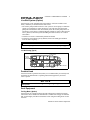
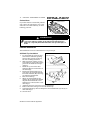
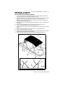
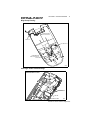
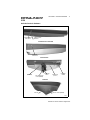
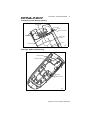
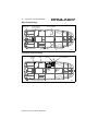
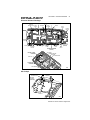
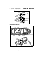
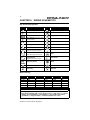
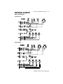
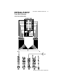
1
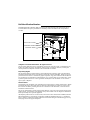
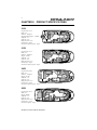
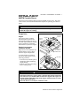
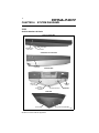
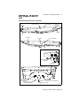
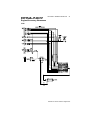
Hull Identification Number:
The Hull Identification Number (HIN) is located on the starboard side of the transom. Be sure to
record the HIN in the space provided above and always refer to the HIN for all correspondence
or orders.
TYPICAL HIN LOCATION
STARBOARD TRANSOM
BOARDING LADDER
© Bayliner Technical Publications. All rights reserved.
No part of this publication may be reproduced, stored in any retrieval system, or transmitted in any
form by any means, electronic, mechanical, photocopying, recording or otherwise, without prior
written permission of Bayliner. Printed in the United States of America.
Proprietary Rights
This document discloses subject matter in which Bayliner has proprietary rights. The information
and design disclosed herein were originated by and are the property of Bayliner. Neither receipt nor
possession thereof confers or transfers any right to reproduce, copy, alter or disclose the document or
any part thereof, any information contained therein, or to construct boats or any item from it, except
by written permission from or written agreement with Bayliner. This document is to be returned
upon request to Bayliner.
General Notes
The material in this document is for information only and is subject to change without notice. While
reasonable efforts have been made in the preparation of this document to assure its accuracy, Bayliner assumes no liability resulting from errors or omissions in this document, or from the use of
information contained herein.
Due to our commitment to product improvement, Bayliner reserves the right to make changes in the
product design, specifications, and equipment at any time without notice or obligation. Illustrations
and/or photos may show optional equipment.
All Bayliner products meet or exceed USCG (Unites States Coast Guard) and/or NMMA (National
Marine Manufacturer’s Association) construction standards. Manufactured with 1,1,1 Trichloroethane, a substance which harms public health and environment during the manufacturing process by
destroying ozone in the upper atmosphere.
CONTENTS
CHAPTER 1: WELCOME ABOARD!
Dealer Service
1
Boating Experience
1
Structural Limitations
1
Engines & Accessories Guidelines
2
Safety Standards
2
Qualified Maintenance
2
Special Care For Moored Boats
3
Hazard Boxes & Symbols
3
CHAPTER 2: PRODUCT SPECIFICATIONS
2109
4
2159
4
2459
4
2659
4
CHAPTER 3: COMPONENTS / SYSTEMS
Electrical System
5
DC Electrical System
6
Navigation Lights
6
AM/FM Cassette Stereo
7
Propulsion
7
Bilge Systems
8
Fuel System
9
10 Freshwater Systems
11 Live Well System (Option)
11 Portable Head
11 Deck Equipment
12 Canvas Installation
CHAPTER 4: SYSTEM DIAGRAMS
14 2109
17 2159
21 2459
25 2659
CONTENTS
CHAPTER 5: WIRING SCHEMATICS
29 Engine/Accessory Harnesses
33 Deck Harnesses
34 Bilge Harness
34 Trolling Motor Harness
34 Water Pump Harness
35 Fuse Block Harness
APPENDIX A: LIMITED WARRANTY
36 What Is Not Covered
36 Other Limitations
36 Your Obligation
This Owner’s Manual Supplement contains
specific information about the following
Rendezvous boats:
2109, 2159, 2459, 2659
1
CHAPTER 1: WELCOME ABOARD!
This owner’s manual supplement provides specific information about your boat
that is not covered in the owner’s manual. Please study the owner’s manual and
this supplement carefully, paying particular attention to Appendix A: LIMITED
WARRANTY. Keep the owner’s manual and this supplement on your boat in a
secure, yet readily available place.
Dealer Service
Make sure you receive a full explanation of all systems from the selling dealer
before taking delivery of your boat. Your selling dealer is your key to service. If
you experience any problems with your new boat, immediately contact the selling
dealer. If for any reason your selling dealer is unable to help, you can call us direct
on our customer service hotline: 360-435-8957 or send us a FAX: 360-403-4235.
Boating Experience
If this is your first boat or if you are changing to a type of boat you are not familiar
with, for your own comfort and safety, please ensure that you obtain handling and
operating experience before assuming command of the boat.
We strongly recommend that you take one of the boating safety classes offered
by the U.S. Power Squadrons or the U.S. Coast Guard Auxiliary. For more
course information, including dates and locations of upcoming classes, contact
the organizations directly:
• U.S. Power Squadrons: 1-888-FOR-USPS (1-888-367-8777) or on the Internet
at: http://www.usps.org
• U.S. Coast Guard Auxiliary: 1-800-368-5647 or on the Internet at:
http://www.cgaux.org
Outside the United States, your selling dealer, national sailing federation or local
yacht club can advise you of local sea schools or competent instructors.
!
WA RNIN G!
CONTROL HAZARD! A qualified operator must be in control of the boat at all
times. DO NOT operate your boat while under the influence of alcohol or drugs.
Structural Limitations
The transom platform and bow platform are designed to be lightweight for proper
boat balance. The load limit for these platforms is 30 pounds per square foot,
evenly distributed.
Rendezvous Owner’s Manual Supplement
2
CHAPTER 1: WELCOME ABOARD!
Engines & Accessories Guidelines
Your boat’s engines and accessories were selected to provide optimum performance
and service. Installing different engines or accessories may cause unwanted handling characteristics. Should you choose to install different engines or add accessories that will affect the boat’s running trim, have an experienced marine technician
perform a safety inspection and handling test before operating your boat again.
Please be advised that certain modifications to your boat can result in cancellation of your limited warranty protection. Always check with your dealer
before making any modifications to your boat.
The engines and accessories installed on your boat come with their own operation
and maintenance manuals. We strongly urge you to read and understand these manuals before operating the engines and accessories.
Safety Standards
Your boat’s mechanical and electrical systems were designed to meet safety standards in effect at the time it was built. Some of these standards were mandated by
law; all of them were designed to insure your safety, and the safety of other people,
vessels and property.
In addition to this supplement, please read the owner’s manual and all
accessory instruction sheets included in your owner’s packet for important
safety standards and hazard information.
!
DAN GEDANGER
R!
PERSONAL SAFETY HAZARD! DO NOT allow anyone to ride on
parts of the boat not designated for such use. Sitting on seat
backs, lounging on the forward deck, bow riding, gunwale riding
or occupying the transom platform while underway is especially
hazardous and WILL cause personal injury or death.
Qualified Maintenance
Failure to maintain your boat’s systems as designed could violate the laws in
your jurisdiction and could expose you and other people to the danger of
bodily injury or accidental death. We recommend that you follow all maintenance instructions provided in the owner’s manual, this supplement, the engine
owner’s manual as well as all accessory instruction sheets and manuals included in
your boat’s owner’s packet.
!
WA RNIN G!
To maintain the integrity and safety of your boat, only qualified personnel
should perform maintenance on, or in any way modify: The steering system,
propulsion system, engine control system, fuel system, environmental control
system, electrical system or navigational system.
Rendezvous Owner’s Manual Supplement
CHAPTER 1: WELCOME ABOARD!
3
Special Care For Moored Boats
If moored in saltwater or fresh water, your boat will collect marine growth on its
hull bottom. This will detract from the boat’s beauty, greatly affect its performance
and may damage the gelcoat. There are two methods of slowing marine growth:
• Periodically haul the boat out of the water and scrub the hull bottom with a bristle
brush and a solution of soap and water.
• Paint the hull below the waterline with a good grade of anti-fouling paint.
NOTIC E
To help seal the hull bottom and reduce the possibility of gelcoat blistering on
moored boats, we recommend the application of an epoxy barrier coating, such
as Interlux, Interprotect 2000E/2001E. The barrier coating should be covered
with several coats of anti-fouling paint.
Many states regulate the chemical content of bottom paints in order to meet
environmental standards. Check with your local dealer about recommended
bottom paints, and about the laws in effect in your area.
Hazard Boxes & Symbols
The hazard boxes and symbols shown below are used throughout this supplement
to call attention to potentially dangerous situations which could lead to either personal injury, death or product damage. We urge you to read all hazard warnings carefully and follow all safety recommendations.
HOT
HAZARD!
EXPLOSION
HAZARD!
ELECTRICAL
HAZARD!
!
OPEN FLAME
HAZARD!
PERSONAL INJURY
& FALLING HAZARD!
ROTATING
PROPELLER HAZARD!
DAN GEDANGER
R!
This box alerts you to immediate hazards which WILL cause severe personal
injury or death if the warning is ignored.
!
WA RNIN G!
This box alerts you to hazards or unsafe practices which COULD result in
severe personal injury or death if the warning is ignored.
!
CAUTIO N!
This box alerts you to hazards or unsafe practices which COULD result in
minor personal injury or cause product or property damage if the warning is
ignored.
NOTIC E
This box calls attention to installation, operation or maintenance information,
which is important to proper operation but is not hazard related.
Rendezvous Owner’s Manual Supplement
4
CHAPTER 2: PRODUCT SPECIFICATIONS
2109
Length overall - 21' 3"
Beam - 8' 3"
Deadrise - 16 degrees
Weight (standard engine) - 3,1458 lb.
Draft hull - 1' 3"
Draft max - 2' 8"
Bridge clearance - 4' 2"
Fuel capacity - 45 gal.
Freshwater capacity (option) - 19 gal.
2159
Length overall - 21' 3"
Beam - 8' 3"
Deadrise - 16 degrees
Weight - 3,750 lb.
Draft hull - 1' 4"
Draft max - 2' 8"
Bridge clearance - 4' 1"
Fuel capacity - 45 gal.
Freshwater capacity (option) - 19 gal.
2459
Length overall - 24' 0"
Beam - 8' 3"
Deadrise - 17 degrees
Weight - 4,333 lb.
Draft hull - 1' 4"
Draft max - 2' 9"
Bridge clearance - 4' 3"
Fuel capacity - 65 gal.
Freshwater capacity (option) - 19 gal.
2659
Length overall - 26' 5"
Beam - 8' 5"
Weight - 4,898 lb.
Draft hull - 1' 1"
Draft max - 2' 6"
Bridge clearance - 4' 5"
Fuel capacity - 57 gal.
Freshwater capacity - 13 gal.
Rendezvous Owner’s Manual Supplement
5
CHAPTER 3: COMPONENTS / SYSTEMS
Electrical System
We strongly recommend that you thoroughly read and understand the electrical sections of the owner’s manual and all accessory manuals included in
your boat’s owner’s packet. Wiring schematics are provided in chapter 5 of this
supplement.
!
DAN GEDANGER
R!
FIRE, SHOCK & EXPLOSION HAZARD!
• DO NOT modify the electrical systems or relevant drawings. Only qualified
personnel should install batteries and/or perform maintenance on the electrical system.
• To minimize the risks of fire and explosion, NEVER install knife switches or
other arcing devices in the fuel compartments. NEVER substitute automotive
parts for marine parts. Electrical, ignition and fuel system parts were
designed and manufactured to comply with rules and regulations that minimize risks of fire and explosion.
!
WA RNIN G!
FIRE & EXPLOSION HAZARD!
• Fuel fumes are heavier than air and will collect in the bilge areas where they
can be accidently ignited. Visually and by smell (sniff test), check the engine
and fuel compartments for fumes or accumulation of fuel. Always operate
the bilge blowers for at least four minutes prior to engine starting, electrical
system maintenance or activation of electrical devices.
• To minimize the danger of fire and explosion, DO NOT expose batteries to
open flame or sparks.
• DO NOT smoke anywhere near the batteries.
!
CAUTIO N!
SHOCK & ELECTRICAL SYSTEM DAMAGE HAZARD!
• NEVER disconnect the battery cables while the engine is running since
damage may occur to your boat’s electrical system components.
• The battery charging system (alternator) installed on your boat are designed to
charge conventional lead-acid batteries. Before installing gel-cell or other new
technology batteries, consult with the battery manufacturer about charging
system requirements.
NOTIC E
Electrical connections are prone to corrosion. To reduce electrical problems
caused by corrosion, keep all electrical connections clean and apply a spray-on
protectant that is designed to protect connections from corrosion.
Rendezvous Owner’s Manual Supplement
6
CHAPTER 3: COMPONENTS / SYSTEMS
DC Electrical System
All Rendezvous models are equipped with a 12 volt DC (direct current) system.
Fuses and Circuit Breakers
• Fuses and circuit breakers for engines and main accessory power are located on
the dash.
• Electronics power is provided at the helm.
• Some equipment may have secondary fuse protection at the unit.
Battery Maintenance
Corroded battery terminals can be cleaned with baking soda and water. After cleaning the terminals, be sure to coat them with a light film of battery terminal lubricant
and tighten all battery connections.
Depth Finder (Option)
Your boat may feature an optional depth finder (depth sounder) at the helm. The
depth finder provides you with measurements of water depth beneath the boat. Be
sure to read the depth finder owner’s manual for detailed operating instructions.
!
WA RNIN G!
• DO NOT use the depth finder as a navigational aid to prevent collision,
grounding, boat damage or personal injury.
• When the boat is moving, submerged objects will not be seen until they are
already under the boat. Bottom depths may change too quickly to allow time
for the boat operator to react. If you suspect shallow water or submerged
objects, operate the boat at very slow speeds.
Navigation Lights
We strongly recommend that you understand navigation light usage by reading the
navigation light section of the owner’s manual. The navigation lights are of top
quality, but you should be aware that failure may periodically occur for a variety of
reasons:
•
•
•
•
There may be a blown fuse - replace the fuse in the switch panel.
The bulb may be burned out - carry spare bulbs for replacement.
A wire may be damaged or may have come loose - repair as required.
The bulb base may be corroded - clean the base and coat it with non-conductive
electrical lubricant.
!
CAUTIO N!
Avoid the storage of gear where it would block navigation lights from view.
Rendezvous Owner’s Manual Supplement
CHAPTER 3: COMPONENTS / SYSTEMS
7
AM/FM Cassette Stereo
Your boat comes standard-equipped with an AM/FM cassette stereo. The stereo
comes with its own instruction manual that explains its operating procedures in
detail.
NOTIC E
AM radio reception may be impaired in areas where reception is limited or
anytime the engines are running.
Propulsion
TYPICAL BILGE BLOWER SYSTEMS
Engine
The owner’s packet contains
detailed engine operation and
maintenance manuals. Be sure to
read and understand these manuals
before operating or performing
maintenance to your boat’s engine.
COLLECTOR
(TYPICAL)
BLOWER
LOUVER
(TYPICAL)
Engine Compartment
Ventilation System
Bilge blowers are installed on all
inboard boats to remove fumes
from the engine compartment.
(26
59
To ensure fresh air circulation,
operate the bilge blowers in the
following situations:
VENT HOSE
(TYPICAL)
GD
)
TRANSOM VENT
BLOWER
VENT HOSE
• At least four (4) minutes prior to
starting the engine and during
engine starting.
• Anytime your boat is operating
below cruising speed.
45
(2
!
9
B)
G
WA RNIN G!
EXPLOSION HAZARD!
• Operation of the blower system is NOT a guarantee that explosive fumes have
been removed. If you smell fuel, DO NOT start the engines. If the engines are
already running, immediately shut off the engines and all electrical accessories
and investigate immediately.
• DO NOT obstruct or modify the ventilation system.
Rendezvous Owner’s Manual Supplement
8
CHAPTER 3: COMPONENTS / SYSTEMS
Bilge Systems
Bilge Pumps
• Your boat is equipped with impeller-type bilge pumps, which are used to pump
water out of the bilge.
• Bilge pumps are controlled by automatic bilge pump float switches (autofloat
switches) and/or switches at the helm.
• Automatic bilge pumps are wired directly to the battery so they will function
even when the boat is completely shut down and left unattended.
NOTIC E
Discharge of oil, oil waste or fuel into navigable waters is prohibited by law.
Violators are subject to legal action by the local authorities.
Bilge Pump Testing
Bilge pumps should be tested often to verify they are working properly. To test a
bilge pump, activate the dash-mounted switch and verify that water in the bilge is
being pumped overboard. If bilge water is present and the pump motor is running
but NOT pumping, inspect the discharge hose for a kink or collapsed area. If no
problems are found, check the bilge pump housing for clogging debris as follows:
To check for clogging debris:
1. Remove the power cartridge:
a. Lift the tab while rotating the
fins counterclockwise.
b. Lift out the power cartridge.
c. Clear debris from the outer housing.
2. Reinstall the power cartridge:
a. Make sure the “O” ring is
properly seated.
b. Coat the “O” ring with a light
film of vegetable or mineral oil.
c. Align the two cams on either side
of the power cartridge with the
two slots on the outer housing
and press the power cartridge
into the housing while twisting
clockwise.
3. Ensure proper reinstallation by
attempting to twist the fins counterclockwise without lifting the tab.
The cartridge should stay in place.
FIN
TAB
TYPICAL
BILGE PUMP
COMPONENTS
LIGHT FILM
OF OIL
CAM
(TYPICAL)
“O” RING
POWER
CARTRIDGE
OUTER
HOUSING
SLOT (TYPICAL)
Autofloat Switches
Automatic bilge pumps use electromagnetic float (autofloat) switches to automatically activate the pump whenever water accumulates above a preset level in the
bilge. One autofloat switch is mounted next to the bilge pump it activates, and is
wired directly to the battery so it will function even when the boat is completely
shut down and left unattended.
Rendezvous Owner’s Manual Supplement
CHAPTER 3: COMPONENTS / SYSTEMS
9
Autofloat switches should be tested often for proper operation as follows:
1.
2.
Push the float switch test
button UP to activate the
bilge pump.
If the pump does NOT
turn on, check the inline
fuse. If the fuse is good
but the switch doesn’t
work, it may indicate a
bad switch or possibly a
low battery.
Push the test button all the
way DOWN to return the
float switch back into the
auto mode.
!
FLOAT SWITCH TESTING
FLOAT SWITCH
TEST BUTTON
SWITCH UP - AUTO MODE;
BILGE PUMP SHOULD
TURN OFF
SWITCH DOWN - AUTO MODE;
BILGE PUMP SHOULD
TURN OFF
CAUTIO N!
When the float switch test is completed, you MUST push the test button all the
way DOWN to return the switch back into auto mode!
Fuel System
Carefully read the fuel system sections of the owner’s manual and the engine
operation manual.
NOTIC E
Discharge of fuel into navigable waters is prohibited by law. Violators are
subject to legal action by the local authorities.
!
WA RNIN G!
FIRE, EXPLOSION AND OPEN FLAME HAZARD!
• It is very important that the fuel system be inspected thoroughly the first time
it is filled and at each subsequent filling.
• The fueling instructions in the owner’s manual and the fuel grade recommendations in the engine operation manual must be followed.
!
CAUTIO N!
Avoid the storage or handling of gear near the fuel lines, fittings and tank.
Fuel Fill Location
The fuel fill receptacle is located on the starboard aft deck of your boat and is
labeled “GAS”. If you experience difficulty when filling the fuel tank, check to see
that the fuel fill and vent lines are free of obstructions and kinks.
Rendezvous Owner’s Manual Supplement
10
CHAPTER 3: COMPONENTS / SYSTEMS
Fuel Quality
TYPICAL FUEL SYSTEM ROUTING
• Refer to your engine manual for fuel
TO FUEL
TO FUEL VENT
FILL FITTING
grade recommendations.
FUEL VENT HOSE
• Make sure your fuel suppliers are
FUEL FILL
reputable and can be relied upon
HOSE
to furnish clean, high quality fuel.
Once you have found such suppliers, keep your tank as full as
possible with their fuel (allowing
for expansion due to temperature
variations). Then, if you are
forced to add a potentially poor
FUEL FEED
quality fuel supply to the tank,
HOSE
the portion of poor quality fuel
will be minimized.
• Consult your selling dealer or local marina about recommended fuel additives
that help prevent fungus or buildup inside the fuel tank.
Anti-siphon Valves
Your boat may feature anti-siphon valves, which are an integral part of the fuel line
barb fitting on gas fuel tanks. Anti-siphon valves are spring loaded and are opened
by fuel pump vacuum. In the unlikely event of a fuel line rupturing, the anti-siphon
valve is designed to prevent the siphoning of fuel from the tank.
!
WA RNIN G!
FIRE/EXPLOSION HAZARD! If an engine problem is caused by fuel starvation, check the anti-siphon valve. If the valve is stuck or clogged, shut down the
engine and replace it. Except in an emergency, NEVER operate the engines
without the anti-siphon valve.
Freshwater Systems
A pressure-demand (cold only) freshwater system comes standard-equipped on the
2659 and is an option on the 2109, 2159 and 2459 Rendezvous models.
• We strongly recommend that you fill the water tank at every opportunity to avoid
the possibility of running short of potable water.
• Water filters installed in your freshwater system should be inspected and cleaned
often.
• When your boat is to be left unattended for long periods of time, pump the water
tank dry to prevent stored water from becoming stagnant and distasteful. Should
it become necessary to disinfect the freshwater system, ask your dealer about
treatments that are available for your boat’s system.
• The water pump switch should be turned OFF whenever the boat is not in use or
whenever the water tank is empty.
Transom Shower
If your boat features a freshwater transom shower, the water pump switch MUST
be activated before using the transom shower. Be sure to read the manufacturer’s
operating instructions, provided in your boat’s owner’s packet.
Rendezvous Owner’s Manual Supplement
CHAPTER 3: COMPONENTS / SYSTEMS
11
Live Well System (Option)
Your boat may come equipped with an optional live well (not available on all
boats), which may be used to hold live fish or bait.
• The aerator pump installed in the live well system is used to pump a continuous
supply of oxygenated raw water into the live well. The switch for the aerator
pump can be found at the dash. Occasionally check the aerator pump when it is
operating to verify that it is pumping adequate amounts of water. If there appears
to be a problem, check the system (including the intake strainer) for weeds or
other debris.
• Overflow raw water is automatically drained overboard.
• To drain live wells that are gravity-drained, remove the stand pipe and allow
water to drain completely.
NOTIC E
The live well pump should be shut OFF whenever underway at planing speeds.
Live Well Routing (Typical)
LIVE WELL WATER
PICKUP HOSE
LIVE WELL
INTAKE
STRAINER
TO LIVE WELL
LIVE WELL
DRAIN
LIVE WELL PUMP
Portable Head
Your boat features a portable head (toilet), we recommend that you carefully read
and follow the manufacturer’s operating instructions supplied in your boat’s
owner’s packet.
NOTIC E
Check with local authorities for regulations regarding the legal use of marine
head systems.
Deck Equipment
Trolling Motor (Option)
Your boat may be equipped with an optional trolling motor. Detailed operating
instructions can be found in the manufacturer’s manual. We strongly recommend
that you thoroughly read these instructions before using the trolling motor for the
first time.
Rendezvous Owner’s Manual Supplement
12
CHAPTER 3: COMPONENTS / SYSTEMS
Pedestal Seat
PEDESTAL SEAT
If your boat features a removable pedestal
seat, remove the seat and stow it in a safe
and secure area while underway or when
trailering your boat.
!
DAN GEDANGER
R!
PERSONAL INJURY HAZARD! NEVER occupy the pedestal seat while
your boat is underway. Sitting on the pedestal seat while the boat is
underway is especially hazardous and WILL cause personal injury or
death.
Canvas Installation
The installation of canvas is intended to be a two person job.
Aft Bimini Top Installation
AFT BIMINI TOP COMPONENTS
1. Lay the bimini top across the tranSTANCHION (TYPICAL)
som with the stanchions pointing
forward. The port side of the top
has four mounting stanchions.
AFT
2. With one person working on each
side of the boat, remove the locking
pins from the middle deck hinges
(point A).
3. Install the eye-end of the main
stanchion (B) between the lobes of
the deck hinge.
4. Reinsert the pin and make sure it
goes all the way through and locks.
The main stanchion (B) is the longest stanchion on both sides.
5. Raise the bimini top.
6. While one person holds the top
upright, the second person attaches
the port and starboard aft corner
AFT
stanchions (C) and (D) to the corner
deck hinges.
7. Attach the port rear cross brace (E) to it’s deck hinge.
8. Remove the canvas storage boot from the bimini top.
9. Unfold the bimini top forward and pin the forward stanchions (G) and (F) to
their deck hinges.
10. Stow the boot.
Rendezvous Owner’s Manual Supplement
CHAPTER 3: COMPONENTS / SYSTEMS
13
Forward Bimini Top Installation (Option)
1. Lay the bimini top across the transom with the stanchions pointing forward.
The bowed-in (forward) stanchions should be on top.
2. Separate the front bow assembly (see point A below) from the canvas by unzipping the main bow pocket (B) and the forward center bow pocket (C).
3. With one person working on each side of the boat, remove the locking pins
from the forward deck hinges (D).
4. Install the end eyes (E) of the forward bow stanchions between the lobes of the
deck hinge.
5. Reinsert the pin and make sure it goes all the way through and locks.
6. Remove the locking pins from the aft deck hinges (F).
7. Install the end eyes (G) of the aft bow stanchions between the lobes of the deck
hinges.
8. Reinsert the pin and make sure it goes all the way through and locks.
9. Remove the bimini top boot and store.
10. Pull the canvas forward, over the forward bow assembly and zip the main stanchion (H) into the forward bow pocket (B).
11. Zip the forward center bow braces (I) as needed to tighten the canvas.
FORWARD BIMINI TOP COMPONENTS
Rendezvous Owner’s Manual Supplement
14
CHAPTER 4: SYSTEM DIAGRAMS
2109
Hullside Hardware & Drains
PORT HULLSIDE VIEW
DECK DRAIN
FORWARD BILGE
PUMP DRAIN
SINK DRAIN
STARBOARD HULLSIDE VIEW
AFT BILGE
PUMP DRAIN
TRANSOM VIEW
STERN EYE
(TYPICAL)
BOARDING
LADDER
LIVE WELL
INTAKE FILTER
(OPTION)
GARBOARD DRAIN
DECK DRAIN
(TYPICAL)
BOW VIEW
BOW EYE
LIVE WELL DRAIN (OPTION)
2109
Rendezvous Owner’s Manual Supplement
CHAPTER 4: SYSTEM DIAGRAMS
15
Bilge Pump Routing
AFT
AFT BILGE PUMP
& FLOAT SWITCH
TO
THRU-HULL
TO THRU-HULL
FORWARD BILGE
PUMP & AUTOFLOAT
SWITCH
2109
Steering & Shifter Cable Routings
UNDERSIDE VIEW OF DECK
THROTTLE &
SHIFTER CABLES
SHIFTER
STEERING CABLE
2109
Rendezvous Owner’s Manual Supplement
16
CHAPTER 4: SYSTEM DIAGRAMS
Electrical Routings
DECK HARNESS
STEP
LIGHT SHIFTER
CHAFFE
PROTECTION
LIGHT
(HEAD)
DASH
FORWARD
BILGE PUMP
BOW
LIGHT
FLOOD
LIGHTS
SPEAKERS
STERN
LIGHT
ENGINE
HOOKUP
WATER
PUMP
FISHPACK
HARNESS
(OPTION)
BOW
LIGHT
COURTESY
LIGHT
TROLLING
MOTOR PLUG
(OPTION)
HULL HARNESS
TO DECK
HARNESS
TO AFT BILGE PUMP
AFT
TO FUEL SENDING UNIT
2109
Freshwater System Routing (Option)
FRESHWATER
TANK
VENT HOSE
TO VENT
WATER FILL FITTING
TO TRANSOM
SHOWER
WATER PUMP
WATER HOSE
(TYPICAL)
TO SINK
2109
Rendezvous Owner’s Manual Supplement
CHAPTER 4: SYSTEM DIAGRAMS
17
2159
Hullside Drains & Hardware
PORT HULLSIDE VIEW
FORWARD BILGE
PUMP DRAIN
DECK DRAIN
SINK DRAIN
STARBOARD HULLSIDE VIEW
AFT BILGE
PUMP DRAIN
TRANSOM VIEW
STERN EYE
(TYPICAL)
LIVE WELL INTAKE
FILTER (OPTION)
GARBOARD
DRAIN
DECK DRAIN
(TYPICAL)
BOARDING
LADDER
BOW VIEW
BOW EYE
LIVE WELL DRAIN (OPTION)
2159
Rendezvous Owner’s Manual Supplement
18
CHAPTER 4: SYSTEM DIAGRAMS
Bilge Pump Routing
AFT BILGE PUMP
TO THRU-HULL
AFT BILGE PUMP
AFT FLOAT SWITCH
FORWARD BILGE PUMP
TO THRU-HULL
FORWARD BILGE PUMP
& FLOAT SWITCH
2159
Rendezvous Owner’s Manual Supplement
CHAPTER 4: SYSTEM DIAGRAMS
19
Freshwater System Routing (Option)
FRESHWATER
TANK
VENT HOSE
TO VENT
WATER FILL FITTING
TO TRANSOM
SHOWER
WATER HOSE
(TYPICAL)
TO SINK
WATER PUMP
2159
Steering & Shifter Cable Routing
UNDERSIDE VIEW OF DECK SHOWN
SHIFTER CABLE
THROTTLE CABLE
SHIFTER
STEERING CABLE
2159
Rendezvous Owner’s Manual Supplement
20
CHAPTER 4: SYSTEM DIAGRAMS
Electrical Harness Routing
DASH
STEP
LIGHT
DECK HARNESS
CHAFFE
PROTECTION
SHIFTER
LIGHT
IN HEAD
BOW
LIGHT
BILGE
PUMP
HORN
FLOOD
LIGHTS
ENGINE
HOOKUP
SPEAKERS
STERN
LIGHT
FUSES
BLOWER
MOTOR
FISHPACK
HARNESS
(OPTION)
WATER
PUMP
COURTESY
LIGHT
TROLLING
MOTOR PLUG
(OPTION)
BOW
LIGHT
HULL ELECTRICAL HARNESS
TO DECK
HARNESS
BATTERY CABLE KIT
POSITIVE
BATTERY CABLE
NEGATIVE BATTERY CABLE
TO BILGE PUMP
BILGE
HARNESS
TO FUEL
SENDING UNIT
2159
Rendezvous Owner’s Manual Supplement
CHAPTER 4: SYSTEM DIAGRAMS
21
2459
Hullside hardware & Drain Locations
FORWARD
BILGE DRAIN
HEAD PORTLIGHT
AFT BILGE
DRAIN
LIVE WELL
DRAIN (OPTION)
BOW EYE
DECK DRAIN
SINK DRAIN
SKI LOCKER DRAIN
DETAILED VIEW OF BOARDING LADDER
TELESCOPING
LADDER
DECK DRAIN
(TYPICAL PORT
& STARBOARD)
LIVE WELL INTAKE
STRAINER (OPTION)
STERN EYE
(TYPICAL PORT & STARBOARD)
GARBOARD DRAIN
2459
Rendezvous Owner’s Manual Supplement
22
CHAPTER 4: SYSTEM DIAGRAMS
Bilge Pump Routing
BILGE HOSE
FORWARD BILGE PUMP
& FLOAT SWITCH
AFT BILGE PUMP
& FLOAT SWITCH
TO THRU-HULL
TO THRU-HULL
BILGE HOSE
2459
Freshwater System Routing
90 DEGREE
ELBOW
WATER
HOSE
T-FITTING
(TYPICAL)
WATER
TANK
TO TRANSOM SHOWER
Rendezvous Owner’s Manual Supplement
TO SINK
90 DEGREE ELBOW
WATER
PUMP
2459
CHAPTER 4: SYSTEM DIAGRAMS
23
Electrical Harness Routings
HULL HARNESS
BILGE PUMP
DASH
CHAFFE
PROTECTION STEP
SHIFTER
LIGHT
IN HEAD
LIGHT
HORN
BOW
LIGHT
FLOOD
LIGHTS
ENGINE
HOOKUP
SPEAKERS
STERN
LIGHT
FUSES
BLOWER
MOTOR
STEP LIGHT
WATER
PUMP
COURTESY
LIGHT
FISHPACK HARNESS
(OPTION)
TROLLING
MOTOR PLUG
(OPTION)
BOW
LIGHT
BATTERY
ENGINE GROUND
BATTERY CABLE
HARNESS
STARTER
AFT BILGE PUMP
FUEL FILL
FUSE BLOCK
HARNESS
FUEL SENDER
2459
Aft Cockpit
ENGINE HATCH
TRANSOM
SHOWER
(OPTION)
MASTER
BREAKER
PANEL
2459
Rendezvous Owner’s Manual Supplement
24
CHAPTER 4: SYSTEM DIAGRAMS
Deck Fill & Pump-out Fittings
VIEW OF PORT SIDE DECK
WATER TANK
VENT (OPTION)
AFT
CLEAT (TYPICAL)
WATER TANK FILL
FITTING (OPTION)
VIEW OF STARBOARD SIDE DECK
WASTE TANK PUMP-OUT
FITTING (OPTION)
WASTE TANK
VENT (OPTION)
HORN
AFT
2459
Transom Hardware
STERN LIGHT
AFT CLEAT
(TYPICAL)
SWIM STEP
SKI TOW RING
TRANSOM GRAB RAIL
FUEL TANK FILL FITTING
& TANK VENT COMBO
Rendezvous Owner’s Manual Supplement
2459
CHAPTER 4: SYSTEM DIAGRAMS
25
2659
Hull Exterior Hardware
PORT HULLSIDE VIEW
FORWARD BILGE
PUMP DRAIN
PORT AFT
BILGE DRAIN
BOW WELL DRAIN
COOLER
STORAGE DRAIN
SINK DRAIN
PORT DECK
DRAIN
STARBOARD HULLSIDE VIEW
PORT AFT DECK DRAIN
STARBOARD AFT
BILGE DRAIN
FORWARD HELM DRAIN
PORT DECK DRAIN
AFT HELM DRAIN
CENTER AFT
BILGE DRAIN
COOLER DRAIN
STARBOARD AFT DECK DRAIN
DETAILED VIEW
TRANSOM VIEW
BOARDING
LABEL
BOARDING
LADDER
STERN EYE
(TYPICAL)
GARBOARD
DRAINS
BOW VIEW
BOW EYE
2659
Rendezvous Owner’s Manual Supplement
26
CHAPTER 4: SYSTEM DIAGRAMS
Freshwater System Routing
(CUTAWAY VIEW)
SINK
FAUCET
TO THRU-HULL
SINK DRAIN
WATER TANK
HOLD DOWN
FRESHWATER
HOLDING TANK
INLINE PUMP
STRAINER
WATER HOSE
(TYPICAL)
WATER PUMP
Electrical Harness Routings
DECK HARNESS
COURTESY
LIGHT
SHIFTER
DASH
LIGHT IN HEAD
NAVIGATION LIGHT
COURTESY
LIGHT
SPEAKER
BATTERY
ENGINE
PLUG
FORWARD
BILGE PUMP
SPEAKER
NAVIGATION LIGHT
WATER PUMP
AFT HULL WIRE HARNESS ROUTING
ENGINE
ACCESSORY
HARNESS
BATTERY
CABLE KIT
2659 GD
Rendezvous Owner’s Manual Supplement
CHAPTER 4: SYSTEM DIAGRAMS
27
Bilge Pump Routings
AFT BILGE PUMPS
TO THRU-HULLS
BILGE HOSE
(TYPICAL)
PORT
STARBOARD AFT
FLOAT SWITCH
STARBOARD AFT
BILGE PUMP
CENTER AFT
FLOAT SWITCH
CENTER AFT
BILGE PUMP
TO
THRU-HULL
PORT AFT
FLOAT SWITCH
PORT AFT
BILGE PUMP
FORWARD BILGE PUMP
AFT
FORWARD
BILGE PUMP
FORWARD
FLOAT SWITCH
BILGE HOSE
PORT HULLSIDE
THRU-HULL
2659 GD
Rendezvous Owner’s Manual Supplement
28
CHAPTER 5: WIRING SCHEMATICS
Key to Electrical Symbols
Symbol
Description
Symbol
Description
Connection (Node)
Gauge
No Connection
Ammeter
Battery
Frequency Meter
Earth Ground: Represents a black
conductor that is the same size as the
colored conductor
12 Volt DC Receptacle
Breaker
Voltmeter
Breaker
Motor/Pump
Fuse
Speaker/Horn/Alarm
Switch:
Float Switch
Single Pole Single Throw (SPST)
Switch:
Plug
Double Pole Single Throw (DPST)
Lighted Switch:
Fuel Sender
Single Pole Single Throw (SPST)
Momentary Switch
Diode
Incandescent Lamp
Current Transformer
Neon Lamp
Solenoid
Wire Color Key
Color Key
Description
B, BLK
Black
G, GR, GRN
Color Key
Green
Description
R, RED
Color Key
Red
Description
BL, BLU
Blue
LT
Light
T, TAN
Tan
BR, BRN
Brown
O, OR, ORG
Orange
W, WH, WHT
White
DK
Dark
PK
Pink
Y, YEL
Yellow
GY, GRY
Gray
PU, PUR, PPL
Purple
NOTIC E
• Wiring diagrams show optional equipment not installed on all models.
• Some boats equipped with a stereo may have silver (-) and copper (+) colored
speaker wires or red/black (-) and red/white (+) port speaker wire colors;
green/black (-) and green/white (+) starboard speaker wire colors.
Rendezvous Owner’s Manual Supplement
CHAPTER 5: WIRING SCHEMATICS
29
Engine/Accessory Harnesses
2109
Rendezvous Owner’s Manual Supplement
30
CHAPTER 5: WIRING SCHEMATICS
2159 & 2459
Rendezvous Owner’s Manual Supplement
CHAPTER 5: WIRING SCHEMATICS
31
2659, Part 1 of 2
Rendezvous Owner’s Manual Supplement
32
CHAPTER 5: WIRING SCHEMATICS
2659, Part 2 of 2
Rendezvous Owner’s Manual Supplement
CHAPTER 5: WIRING SCHEMATICS
33
Deck Harnesses
2109 & 2159
2459 & 2659
Rendezvous Owner’s Manual Supplement
34
CHAPTER 5: WIRING SCHEMATICS
Bilge Harness
2109, 2159, 2459 & 2659
Trolling Motor Harness
2109, 2159, 2459 & 2659
Water Pump Harness
2109, 2159, 2459 & 2659
Rendezvous Owner’s Manual Supplement
CHAPTER 5: WIRING SCHEMATICS
35
Fuse Block Harness
2109, 2159, 2459 & 2659
Rendezvous Owner’s Manual Supplement
36
APPENDIX A: LIMITED WARRANTY
Bayliner warrants to the original purchasers of its Rendezvous model boats, purchased from an authorized dealer, operated under normal, noncommercial use that the selling dealer will: (A) Repair any structural hull defect which occurs within five (5) years of the date of delivery; and (B) Repair or replace any
parts found to be defective in factory material or workmanship within one (1) year of the date of delivery.
What Is Not Covered
This limited warranty does not apply to:
1.
2.
3.
4.
5.
6.
7.
8.
Engines, drive trains, controls, props, batteries, or other equipment or accessories carrying their
own individual warranties;
Engines, parts or accessories not installed by Bayliner;
Plexiglass windscreen breakage; rainwater leakage on runabout models; rainwater leakage
through convertible tops; minor gelcoat discoloration, cracks or crazing or air voids;
Hull blisters that form below the waterline;
Normal deterioration, i.e. wear, tear, or corrosion of hardware, vinyl, tops, vinyl and fabric upholstery, plastic, metal, wood, or trim tape;
Any Bayliner boat which has been overpowered according to the maximum horsepower specifications on the capacity plate provided on each Bayliner outboard boat;
Any Bayliner boat used for commercial purposes;
Any defect caused by failure of the customer to provide reasonable care and maintenance.
Other Limitations
THERE ARE NO OTHER EXPRESS WARRANTIES ON THIS BOAT. TO THE EXTENT
ALLOWED BY LAW:
1.
2.
3.
ANY IMPLIED WARRANTY OF MERCHANTABILITY OR FITNESS FOR A PARTICULAR
PURPOSE IS LIMITED TO THE DURATION OF ONE YEAR.
Neither Bayliner nor the selling dealer shall have any responsibility for loss of use of the boat,
loss of time, inconvenience, commercial loss or consequential damages.
Some jurisdictions do not allow limitations on how long any implied warranty lasts, so the above
limitation may not apply to you. Some jurisdictions do not allow the exclusion or limitation of
incidental or consequential damages, so the above limitation or exclusion may not apply to you.
This limited warranty gives you specific legal rights, and you may also have other rights which
vary from state to state.
Your Obligation
In order to comply with regulations, it is essential that your limited warranty registration card be submitted
within 30 days of delivery of your boat. Return of the limited warranty registration card is a condition precedent to limited warranty coverage. Before any warranty work is performed, we require that you contact
your dealer to request warranty assistance.
YOU MUST GIVE US WRITTEN NOTICE OF YOUR WARRANTY CLAIM PRIOR TO THE EXPIRATION OF YOUR LIMITED WARRANTY AND ALLOW US AN OPPORTUNITY TO RESOLVE
THE MATTER.
We require that you return your boat, at your expense, to your selling dealer or, if necessary, to the Bayliner factory. You will be responsible for all transportation, haulouts and other expenses incurred in returning the boat for warranty service.
Bayliner Marine Corporation
PO Box 9029
Everett, WA 98206
Phone: 360-435-8957
FAX: 360-403-4235
Rendezvous Owner’s Manual Supplement
Part Number 104287
A Brunswick Company
Bayliner • P.O. Box 9029 • Everett, WA 98206 • 360-435-5571