1
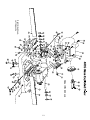
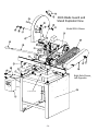
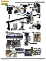
10.01.12
INSTRUCTION BULLETIN
& MAINTENANCE MANUAL
FOR CTD A500
MODELS A500, A500M
CTD MODEL NO:
CTD SERIAL NO:
MANUFACTURE DATE:
DISTRIBUTOR PURCHASED THROUGH:
(IF ANY)
CTD MACHINES
2300 East 11th Street
Los Angeles, CA 90021-2817
Tele (213) 689-4455 • FAX (213) 689-1255
World Wide Web: http://www.ctdsaw.com
e-mail: [email protected]
SUBJECT
PAGE NO.
Machine Requirements………………………………………………………………………………..
2
Installation and Set-Up………………………………………………………………………………..
3
Electrical Installation………………………………………………………………………………….
5
Safety Instructions…………………………………………………………………………………….
6
How to Operate the Machine…………………………………………………………………………..
6
Air Pneumatics………………………………………………………………………………………..
10
Preventive Maintenance………………………………………………………………………………..
13
Repair and Service……………………………………………………………………………………
13
Spindle and Pivot Shaft Diagrams…………………………………………………………………........
14,15
400S Base Exploded View…………………………………………………………………………….
16,17
400S Blade Guard exploded view................…………………………………………………………
18,19
Parts List………………………………………………………………………………………………
20
Machine Requirements:
MODEL NO:_________________
Height
SERIAL NO:_________________
Height
16” Blade
20” Blade
Width
16” Blade
16” Blade - 90° Cutting Capacities A500, A500M
20” Blade - 90° Cutting Capacities A500, A500M
Width
20” Blade
16” Blade - 45° Cutting Capacities A500. A500M
20” Blade - 45° Cutting Capacities A500, A500M
Pneumatic Requirements: (if applicable) 2 CFM per 10 strokes at 75 PSI (.086 cubic meters at 5.4 kg/cm2)
Dust Collection Requirements: 1100 CFM at 4” outlets
Electrical Requirements: Based on one motor per machine
Motor Size
7-1/2 H.P. 3 Phase, 230 Volt
7-1/2 H.P. 3 Phase, 460 Volt
10 H.P. 3 Phase, 230 Volt
10 H.P. 3 Phase, 460 Volt
Required Amperage
20 amps
10 amps
26 amps
13 amps
Cutting Tool Requirements: Heavy, rigid plate blades.
16” blades: .120 to .130 plate
-2-
Breaker Needed
30 amp
20 amp
40 amp
20 amp
20” blades: .150 to .160 plate
Space Requirements
Installation and Set Up:
The CTD saw you have purchased is designed to cut wood, aluminum, plastic and steel, with of course the proper
blade and conditions. For the material you are cutting, please refer to the cutting instructions for each material type.
The 400 Series machines use a NEMA 213T or 215T, 7-1/2 H.P., 1725 RPM, 60 Hertz TEFC Motor. CTD uses a
speed-up so that the blade will run at approximately 12,500 SFPM on a 16” blade and 14,000 SFPM on a 20” blade.
IMPORTANT: Before operating saw, please be sure to read the “SAFETY INSTRUCTIONS TO THE
OPERATOR” (see Page No. 6).
Note: The floor stand must be shimmed, leveled and bolted to the floor, or framed in to eliminate vibration. Use
holes provided in bottom of floor stand. All machines have been completely assembled at the factory, then disassembled for shipment.
Assembly of Support Tables and Measuring Gages:
Standard Machine—The standard model has been completely assembled. Fences are set at the centerline of the
blade (see Diagram “D“ on Page No. 4). Adjust fences forward if necessary for your particular material. The
machine base must be level. The incoming material and outgoing material must lay flat on the machine base (see
Diagram “F“ on Page No. 8).
Assembly of Tables to Floor Stand:
1. Assemble leg to support table with 3/8-16 bolts and nuts provided. Turn table upside down and attach leg to
tablewith leg rising vertically. Note: The hole in the table (when mounted properly) should be toward the
back of the table and far away from the blade to attach Fence Support Angle, P/N BF16 (see Diagram “A“).
2. Attach Table, P/N BF17 to machine floor stand on Angle Bracket, P/N BF05C. Use 3/8-16 bolts and nuts
provided on angle bracket.
Diagram “A”
-3-
Attaching Extended Fence Gage:
1. Place Extended Fence Gage (5/8 x 3-1/2” material) on table. Bolt to fence bracket with screws provided.
Adjust fence gage so measurement rule is correctly set:
A. With a scale or ruler touching the side of the tips of the blade, measure a distance away from blade.
Be sure the ruler and the tape on the fence gage read the same. This may be visually deceiving.
Use a 90° square to check.
B. Adjust fence, left to right, as necessary.
C. Both fences, left and right, must be in perfect alignment. Use a long straight edge for this purpose.
(see Diagrams “B” below and Diagram “E” on Page No. 7).
Diagram “B”
Blade Installation:
Before setting blades on spindle, always shut off or disconnect air supply. With motor OFF and power disconnected,
loosen wing nut on Bottom Blade Guard Strap, P/N 6F07B (see Diagram “D“ below) and swing down. Now, lift
main blade guard, exposing Spindle Assembly.
1. Remove Spindle Nut, P/N 4B1P48 and Outer Flange, P/N 4BM43. If necessary, hold blade in hand with rag
or lower blade into a piece of wood. Push down with a wrench.
2. Place blade on spindle with tips pointing down. Make sure Slinger (inner flange), P/N 4BM44, and blade
surface are clean before putting blade on spindle. This is a critical surface and is ground within .0005
flatness. Any debris or dust will wear this surface. Wipe both surfaces (blade and slinger) with a clean rag.
A. The blade must ALWAYS rotate to the rear of the machine on the underside of the blade
(see Diagram “D“). Always check rotation before cutting a piece of material.
3. Replace Outer Flange, P/N 4BM43 and Spindle Nut, P/N 4B1P48 as before and tighten (refer to
Diagram “C”). Pull up with wrench. Do not over-tighten. Snugging the blade is all that is necessary.
If blades were purchased from CTD, your machine has been set with your blades. If not, blade diameters may
vary. Check to see if the blade contacts the base or disc in the down position. If repositioning is necessary, adjust
down stop bolt located under Arm Casting, P/N 4BC01 (refer to Page No. 11).
Diagram “C”
slinger
Diagram “D”
blade
flange
arm
casting
spindle
nut
spindle
-4-
These machines are general purpose in their design, therefore the user should attach any additional guarding to the blade guard or table base if the cutting application causes
unsafe blade exposure.
This label is attached to the blade guard. Never put hand or fingers near or under the moving
blade. Use a piece of wood to remove short pieces from saw.
Electrical Installation:
The CTD A500 Series Cut-Off Saws use 7-1/2 H.P. three phase 1725 RPM, 60 HZ TEFC (totally enclosed fan
cooled) motors on a NEMA 213T or 215T Frame. CTD uses a speed up drive so that the blade will run at approximately 2900 RPM for a 16” blade and 2700 RPM for a 20” blade. Optional motors are 10 H.P. & 15 H.P.
Electrical installation should be performed by a qualified and certified electrician. A lock-out or disconnect switch
is located on the magnetic starter between your main electrical panel and the machine. This disconnect switch is
used to shut off power to the machine and should be used whenever the blades are changed or at any time the machine
is serviced and the blade is exposed. A Magnetic Starter (OSHA required) is standard on the machine. The starter
protects the motor from overheating and will not allow the motor to restart itself after power outages or undervoltage
situations.
Electrical Installation of Power to Starter by a Qualified Electrician:
All wiring from the motor to the starter has been completed and tested at the factory several times. The voltage has
been clearly tagged. DO NOT CONNECT ANY VOLTAGE THAT IS DIFFERENT THAN THE TAGGED VOLTAGE,
AS THIS MAY CAUSE SEVERE DAMAGE AND DANGER. Consult the factory if any changes are needed. Bring
power lines to the top of the Magnetic Starter. Use dust proof connectors if available.
Three Phase Motors:
Connect incoming power line leads to L1 (line 1), L2, and L3. (See Wiring Diagram for Three Phase Motors
below.) Green ground wire must be grounded to enclosure. Be sure to check rotation as polarities may be different. The blade must rotate down and to the rear on the underside of the blade (see Diagram “D” on Page No. 4).
If a change in rotation is necessary, reverse any two of the incoming power wires. Example: If the blades are
running backwards and incoming wires are connected White L1, Black L2, and Red L3, switch the Black wire with
the Red so that Black is connected to L3 and
Red is connected to L2. This will change the motor to rotate properly.
Motor Load Amperes
Motor Size
208 Volt
230 Volt
460 Volt
Wiring Diagram for Magnetic Starter
7-1/2 H.P., 3 Phase 21.5 amps
20 amps
10 amps
10 H.P., 3 Phase
28 amps
26 amps
13 amps
-5-
Safety Instructions to the Operator:
1. KNOW YOUR CTD SAW. Read this instruction manual carefully. Learn the operation, application, and
limitations, as well as the specific potential hazards peculiar to this machine.
2. Avoid accidental starting. Make sure disconnect switch is OFF before plugging in power cord. A Magnetic
Starter
(which is OSHA required by user) with a disconnect switch is provided standard on the machine to give the
operator
added protection.
3. Always use a plug equipped with a ground.
4. Always keep blade guard in place. Do not wire-up or chain-up, so that blade is exposed.
5. Be sure all unnecessary tools are removed from machine before turning on power.
6. Use safety goggles. Also use a face or dust mask if operation is dusty.
7. Support work. To maintain control of work at all times, it is necessary that material be level with cutting
surface.
8. Wear proper apparel. Do not wear loose clothing or jewelry. Do not wear a tie or gloves. These items can
get caught in the moving parts of the machines.
9. Do not over-reach. Keep your proper footing and balance at all times.
10. Maintain your machine in top condition. Use proper blades. Clean machine weekly for proper maintenance.
11. Keep work area clean. Cluttered areas, benches and slippery floors invite accidents.
12. Avoid dangerous environments. Keep work area well illuminated.
13. Wear ear protection if exposed to long periods of very noisy shop operations.
14. Keep visitors away. All visitors should be kept a safe distance from work area.
15. Do not force the machine. The saw will do a better job and be safer to operate at the speed for which it was
designed. Forcing the saw can be very hazardous to the operator.
16. Use recommended accessories. Use of other accessories may be hazardous. Use this instruction manual or
consult CTD for the proper accessories available.
17. Do not drown the blade using a steady stream of coolant when cutting non-ferrous material. Only spray the
work to cool it.
18. Be sure to use the proper blade for the particular material to be cut.
19. Disconnect power cord before adjusting, servicing, and before changing belts, also for installing accessories.
20. Safety is a combination of operator COMMON SENSE and ALERTNESS at all times when the machine is
being used.
21. WARNING!!! DO NOT ALLOW FAMILIARITY (GAINED FROM FREQUENT USE OF YOUR SAW )TO
DULL YOUR AWARENESS!! ALWAYS REMEMBER THAT A CARELESS FRACTION OF A SECOND IS
SUFFICIENT TO INFLICT SEVERE INJURY!!
How to Operate the A500 Series Automatic Cut-Off Saws:
Before operating the machine, please read the “ SAFETY INSTRUCTIONS TO THE OPERATOR” above. Other
important information and features need to be learned before operating the machine.
Rotation:
The blade must rotate to the rear of the machine on the underside of the blades (see Diagram “D” on Page
No. 7).
Blade Guard:
The blade and belt drive are enclosed.
ALWAYS keep Blade Guard and machine enclosure closed during the
cutting cycle.
Positioning the Work:
Fences should be set so that the centerline of the work is either to the front, or on the centerline of the blade (see
Diagram “D”). Fences must be adjusted so that short pieces cannot be trapped between the blade and the
fences. Fences must be in line with each other—front to back (see Diagram “E”). If very short pieces are to be
cut, a piece of wood or aluminum can be fixed to the table to make a sub-table, which will stop pieces from being
trapped between the blade and the saw slot (see Diagram “G” on Page No. 8).
-6-
Angle Adjustments on Model A500M:
To change the angle:
1. Pull back spring loaded mitre locking pin & handle assembly & rotate to the right or left. This prevents the
pin from engaging. Mitre lock pin & handle will lock in the open position.
2. Make sure mitre lock down bolt (located in the center of the pivot bracket-see Diagram “D” & “E”) is
loosened.
3. To lock in at preset angles, rotate sawhead and disc near the desired angle aligning with zero mark on base.
4. Turn mitre locking handle to center position, and the spring loaded pin & handle will automatically engage
into preset angle settings. The preset angle settings are 45°, 30°, 22 ½°, 15°, 0° on both sides of the
centerline or zero point. Do not let the spring loaded mitre locking pin & handle engage in several
degree settings as you rotate the mitre base disc. This will cause excess wear on preset angle settings.
5. For all angles that are not preset, follow instructions under #1 to lock handle in the open position.
Simply align degree quadrant on disc with zero mark on base and tighten down intermediate mitre lock
handle located in base.
Clamping and Work Slippage:
The work must never be allowed to move or vibrate as it is being cut. When the work is positioned against a stop,
it must be clamped either by hand holding or by pneumatic air clamps. Never allow unclamped work between the
blade and the stop, as the blade can grab the material and throw it—thereby causing damage to the blade, the
machine, and possibly harming the operator. CTD offers both Horizontal Air Vises and Vertical Clamps. The
Horizontal Air Vise pushes the material backwards against the rear fence. Vertical Clamps hold the material
down, against the table base. The clamps are actuated prior to the saw head. by pushing a hand valve. Check
your material for squareness using a 90° square. Material that is out of square will move when it is cut, causing
irregular mitres. (See “IRREGULAR MITRES” on Page No. 14.) Additional tooling may be needed. Consult
factory for more information.
Cutting the Material:
The material to be cut (both the incoming pieces and the cut pieces) must lay flat on the table base, or the blade
may bind the material. THIS CAN DAMAGE THE BLADE OR THROW THE CUT PIECE OUT OF THE
SAW, POSSIBLY HARMING THE OPERATOR (see Diagram “F”).
-7-
Diagram “F”
Vertical Clamp Assembly
Diagram “G”
Removing Material From the Blade:
If the machine is stalled while cutting, immediately shut saw off and disconnect power. NEVER attempt to free the
blade while the motor is still on. If a piece is bound on the blade, do not attempt to raise the blade out of the material.
Instead, tap the piece down on both sides of the blade with light pressure until the piece has freed the blade.
Cutting Wood:
While wood is generally soft and simpler to cut than aluminum, it requires that the material be held in place as the
blade passes through the material. CTD suggests using a Carbide Blade with Alternate Top Bevel (AT) for lighter
wood sections and picture frame mouldings. This type of blade gives the finest of finishes. No ONE blade will cut
all material perfectly. High lacquers or jesso covered moulding may require a special modified blade for best results.
Consult factory. Never use a wood blade to cut aluminum, as it will chip and fracture the carbide tips of the blade.
Cutting Plastic; High Lacquers,or jesso Mouldings:
Plastic can be cut as easily as wood on the A500 Series Saws. H.L. & Jesso Mouldings can quickly dull carbide
blades ground for wood. It is important to clamp the material as close as possible to the blade and support it by use
of fixtures. CTD offers Horizontal and Vertical Clamps for this application. Additional tooling may be required.
Cutting Aluminum:
As with cutting any material, it is important that aluminum be clamped properly. Precision blades are required
for accurate cutting. CTD suggests and uses a Triple Chip Grind on all its non-ferrous Carbide Blades. When
cutting aluminum, or other non-ferrous materials, it is essential that the blades be lubricated with a Sawblade
Lubrication System or other blade lubricating system for the finest finish. See “Sawblade Lubrication System” on
the next page for more details.
Combination Blades:
Any combination blade is basically an aluminum cutting blade. Significant blade life in between sharpenings
will be lost if a blade is used for cutting both aluminum and wood. The amount of production for either wood
or aluminum should be the determining factor in the assessment of the particular blade type to be used. Please
consult factory.
-8-
Sawblade Lubrication System:
The Sawblade Lubrication System is used when cutting aluminum or other non-ferrous materials. This system
normally uses a Water Soluble Oil mixture of 10 parts water to one part oil. The system operates by siphoning
the lubrication up the line to the spray nozzle. Any air leak will cause inconsistent fluid flow to the spray nozzle.
BE SURE your fluid is free from chips and other debris. A fluid container supplied with the machine contains
a One-Way Check Valve, Part No. B3P96 at the end of the clear fluid line. This check valve helps to hold the
lubrication in the line. However, after a couple of minutes, the lubrication or oil will back-flow into the container.
Priming of the system may be necessary if the machine has been standing without use. The system may be shut
off by closing the toggle valve next to the vacuum pump. The fluid must be clean or the Vacuum Pump will clog.
B3P195
B3P61
P-
Va cuum Lub rication Pum p
P art N o. B 3P 195
(P+)+(P-)
B3P100
B3P198
B3P196
CTD M A CH IN ES , IN C.
P+
LO S AN GELES, CA
USA
Part No.
Description
B3P199
B3P195
Vacuum Pump
B3P196
Link Tubing
B3P197
B3P197
Nozzle Fitting
B3P198
1/8” NPT Adapter
B3P199
1/4” Elbow
B3P61
Shut Off Toggle Valve
B3P100
1/8” NPT to 1/4” tube fitting
B3P96
Check Valve
B3P97
Lubricant Container
BF30
Bracket for SLS
CTD Bio Lubrication System:
The CTD biodegradable lubrication system operates by pulse spraying a minute amount of biodegradable
lubricant directly on to the saw tooth of the blade in time-measured increments. The majority of the lubricant
then dissipates with the heat of the cutting action. Chips coming off the blade are hot and dry, and are more
easily collected. (See specific instructions included with system.)
-9-
Guarding:
The belt drive is completely enclosed with a fabricated guard. The blade guard coversand the machine shield must
be down and closed for the machine to cycle through the cut. The left and right hinging doors must be closed and
locked before any cutting should take place. The operator must not be exposed to an unguarded blade. The
hands or fingers must never be allowed to come in close proximity to the blade—for certain, never under the
blade. Cut off pieces that are short must be removed with a piece of wood or an air blast.
Fences or Back Stops:
The CTD A500 saw is provided with accurately machined fences. This feature allows the operator to easily adjust
the position of the fences for the best, safe condition. (see “Position of Work” below). It is essential that all fences be
adjusted front to back, in the same plane. The fences must also be adjusted so that the shortest cut off piece will not
be able to slip between the blade and fence. Likewise, short pieces must not be allowed to slip between the blade and
the slot in the base. Danger to the operator and blade may result if either of these situations are allowed to occur.
Position of Work:
The fences must be set so that the centerline of the work is either to the front or on the centerline of the blade. If the
work is cut on, or to the front of the centerline of the blade, the machine is absolutely safe—even if the motor is
overloaded and the blade is stalled. The action will drive the work down and to the rear. If the material is set behind
the centerline, there is a chance of the material being lifted up by the cutting action.
Material Not Flat on Table:
It is necessary that the material lay flat on the table. If long material is to be cut off, the conveyor or work supports
must be in exact alignment with the top of the table. If the stock supports are above or below the table, the material
will bind the blade, slip or rise up as it is being cut. All back stops or fences must be in the same plane, or when the
material is cut, it may tend to slip or move, causing inaccurate cuts.
Clamping and Work Slippage:
The work must never be allowed to slip as it is being cut. Due to the wide variety of work, clamping requirements
vary considerably.
Clamping:
In the cutting of aluminum extrusions, often times thin legs or projections must be properly supported to avoid
vibrations. Also, round materials must be securely clamped. Jaws for the vise clamps may be shaped to fit the
contours of the individual piece, thus eliminating clamping and feeding problems. The rear jaws of the A480E vises
have three positions. The front and rear jaws can be set 12” apart at the widest setting. The positioning of the front
jaws is limited by 3” travel of the cylinder shafts. However, they are adjustable another 3” in slots using lock down
bolt. (See Diagram C #123 on Page No. 28).
-page 10-
SUGGESTED SPECIAL TOOLING FOR CUTTING ROUNDS ON A500
Drill and tap to suit Front and back Jaws
Blades:
High speed cut-off machines are a variation of a milling machine and the same principles concerning the cutter apply.
Regardless of the precision built into the machine, it will not function well unless it is used in conjunction with sharp
blades, designed for the specific job of cutting to be accomplished.
Cutting of Aluminum and Non-Ferrous Metals:
High speed sawing of aluminum and non-ferrous metals is the most economical and accurate method devised to date.
Milling machine tolerances can be easily held along with extremely fine surface finishes—down to 40 RMS under
ideal circumstances.
Carbide Blades:
Carbide Blades have proven themselves over the last several years to be, by far, the most economical for production
cutting. Carbide Blades must be handled with extreme care, as they are extremely brittle and can be easily damaged.
The tips are brazed to a carbon steel plate, which has a tooth configuration machined into it. The blades can be
repaired and retipped—even the teeth and the plate can be rebuilt to bring the blade up to its original condition. The
number of teeth will vary considerably depending on the material to be cut. However, for aluminum extrusions, a 96
tooth blade is normally used. For the cutting of heavy extrusions or solid stock, usually from 40 to 60 teeth should be
used. The kerf loss of the carbide blades is approximately .150 for a 16” blade, or .180 for a 20” blade.
For cutting hard wood sections, such as hard rock maple, we recommend a 100 tooth special trim design
blade. This blade gives a fine, smooth finish to the cut piece. Blades must be sharpened regularly if fine
finishes are required.
-page 11-
Air Supply:
The air supply must be turned off and all electrics disconnected before making adjustments on the power feed.
A working pressure of 75 PSI (pounds per square inch at 5.4 kg/cm2) is required. An industrial-type compressor
of at least 5 CFM (cubic feet per minute) is recommended. An additional 3 CFM is required for Spray Mists. A
conveniently located valve should be supplied by the user to shut off the air line. Arms should be raised or
lowered by hand when setting up machine. The machine must use clean, filtered air. The speed of descent of
the saw head will vary if the air pressure varies.
FR:
An Air Filter/Regulator installed ahead of the air inlet to the machine. This system helps prevent foreign material from entering the system. The FR is comprised of two different components.
1. The Air Filter Bowl is located on the left side and is provided with an automatic drain. This collects and
then releases foreign matter and condensation collected by the air filter.
2. The Pressure Regulator, which is located on top of the air filter, controls the amount of air pressure allowed
into the system. An operating pressure of 75 PSI @ 5.4 kg/cm2 is required. (This is set at the factory.)
All air cylinders on the saw are “Lubed for Life”; and do not require a lubricator. All A500 series miter saws are
equipped with an air cushion beneath the pivot bracket. When the knob in the front right corner of the table base is
switched on, the resulting cushion of air beneath the pivot bracket facilitates movement of the head to different
mitering positions.
Air Filter/Regulator
Trouble Shooting the Pneumatic System for Downfeed of Saw Head:
If the Air Feed no longer has smooth action, check the Hydrocheck oil level. See separate instructions on
Hydrocheck.. If there is no Speed Control, the Hydrocheck may need oil. Consult factory. If air is leaking
from the bottom of the cylinder, replace Cylinder with Part No. B3P306 or P/N B3P308.
4-Way Valve:
The 4-Way Valve is the main control, five port valve located on the Air Feed Unit. If the saw is sticking in the
up or down position, the spool located in the valve probably is not shifting from side to side as necessary. This
condition is caused by unclean air passing through the system. The internal parts become gummed up, and the
air pressure can no longer shift the spool. A broken spring in the valve is another common cause. A 4-Way
Valve Repair Kit, P/N B3P76 is available for the valve.
Air Hold Down Clamps for the Material:
Both Horizontal Air Vises or Vertical Air Clamps are available and can be purchased as an optional accessory.
These clamps pneumatically hold the material in place when the saw blade is cutting the material. If clamps are
not purchased, the operator MUST HAND HOLD THE MATERIAL. The clamps are controlled by a 3-Way Valve
mounted on the bottom of the Power Feed Unit. When the machine is in the rest position, the Upstroke Stud
contacts the 3-Way Valve, LV1. As soon as the Hand Valve is tripped, the clamps move into position. A manual
shut-off for the clamps is provided should you not want to use the clamps for a particular material.
-12-
Cutting Speeds:
The rate at which the blade cuts the material varies considerably depending on the type of:
1. Material and the size of the section to be cut
2. Blade being used
3. Surface finish required
4. Speed which may be required to accomplish the cutting job
The essential thing to be remembered (regardless of what the conditions are) is that the blade must always
be able to cut. The blade must never be allowed to dwell in the work. In general, the machine should be
used to its greatest potential for rapidly cutting off the material.
Downfeed Adjustment Speed: A labeled knob is provided at the front of the doors to adjust the down
stroke speed without opening the doors or safety covers.
An air shut-off valve has been provided at the air inlet. Caution, shut off air supply prior to adjustment or
repair.
The blade is rotating at approximately 2900 RPM for 16” machines, and 2700 RPM for 20” machines. If
fine surface finishes are required, a constant even pressure must be applied when cutting through the
material. An Air Hydraulic Power Downfeed of the saw head has been provided.
Proximity
Switch
#9
A4B5P12MM
Air Hydraulic Power Downfeed
Blade Guard
& Power Feed
Support
A4F133
Hydrocheck
B3P146-16”
B3P148-20”
Cylinder
Support Brkt.
A4M159
Air Cylinder
B3P306-16”
B3P308-20”
Downstroke
Speed Control
Saw
Downstroke
Adjustment
Downstroke
Limit & Reverse
Block
A4M189
Flow
Control
Valve
B3P67
Inside Blade
Guard
A4E190
Hydro Sensor
Brkt. Btm.
A4M163
Clevis
15M26
-13-
Bumper
157P73 &
Bumper Ring
15M86
Hydro Sensor
Brkt. Top
A4M166
Proximity
Switch
#2 & #3
A4B5P18MM
Speed Control of Blade Movement:
The downstroke speed of the blade is controlled by the Hydrocheck, P/N B3P146 or P/N B3P148 located next to
the main drive Cylinder, P/N B3P306 or P/N B3P308. The Upstroke Control Valve, P/N B3P60 is located in
port No. 5 of the main control Valve, P/N B3P73. Simply rotate head of valve and adjust in to slow down, or
out to speed up. If not equipped with a hydrocheck, the down speed is regulated by a flow control valve (P/N
B3P60) near the base of the main cylinder.
Preventative Maintenance:
The 400 Series machines are relatively easy machines to operate and maintain. Following is a weekly check list
of General Maintenance items. The best preventative maintenance advise is to CLEAN THE MACHINE DAILY,
especially around the pivot points on the machine.
Lubrication and Adjustments of Bearings:
NO LUBRICATION OR ADJUSTMENTS ARE REQUIRED. All CTD cut-off saws are assembled using
sealed, prelubricated ball bearings. The spindle and pivot assembly are constructed using preloaded belleville
springs. These springs eliminate the need for adjustments of bearings and also greatly increase the life of the
bearings.
General Maintenance Weekly Check List:
Always disconnect electrical power and air supply.
1. Keep machine clean—especially around pivot bracket and pivot bearings.
2. Blow off and clean around the cylinder
3. Check Air Filter Bowl for water and condensation build up.
4. Remove any scrap pieces and dust build up from inside floor stand.
5. Check monthly:
A. For excessive belt wear
B. Make sure motor pulley set screws are tight.
Repair and Service:
Always use CTD factory authorized replacement parts and consult factory before making any repairs or
adjustments which may be unclear.
Fence Alignment and 45° Angle Adjustment of Blades:
All machines are preset at the factory for perfect 90° and 45° mitre cuts. If any adjustments are necessary:
1. Check alignment of fences—left to right as shown in Diagram “E” on Page No. 7. Use a two foot steel scale
or quality precision straight edge and lay flat on table base. Butt edge against fence bracket and long measuring gage (if purchased). Touch the outside corner of the straight edge. If one side of the straight edge
pulls away from the fence, then the long fence gage is not in alignment with the Right Fence, P/N 400M05.
2. Loosen 3/8-16 lock nut on Left Fence Bracket, P/N 41C04L and Fence Support Angle, P/N BF16. Clean
all surfaces of dirt or dust, and re-assemble as before (see Diagrams “A” & “B” on Pages No. 3 & 4).
3. Re-align right fence to left fence with your straight edge. Once you are sure both fences are in alignment,
you now have a reference point to check your 45° mitre.
-14-
Safety Instructions to the Operator:
1. KNOW YOUR CTD SAW. Read this instruction manual carefully. Learn the operation, application,
and limitations, as well as the specific potential hazards peculiar to this machine.
2. Avoid accidental starting. Make sure switch is OFF before plugging in power cord. A Magnetic
Starter (which is OSHA required by user) is provided standard on the machine to give the operator
added protection.
3. Always use a plug equipped with a ground.
4. Always keep blade guard in place. Do not wire-up or chain-up, so that blade is exposed.
5. Be sure all unnecessary tools are removed from machine before turning on power.
6. Use safety goggles. Also use a face or dust mask if operation is dusty.
7. Support work. To maintain control of work at all times, it is necessary that material be level with
cutting surface.
8. Wear proper apparel. Do not wear loose clothing or jewelry. Do not wear a tie or gloves. These
items can get caught in the moving parts of the machines.
9. Do not over-reach. Keep your proper footing and balance at all times.
10. Maintain your machine in top condition. Use proper blades. Clean machine weekly for proper
maintenance.
11. Keep work area clean. Cluttered areas, benches and slippery floors invite accidents.
12. Avoid dangerous environments. Keep work area well illuminated.
13. Wear ear protection if exposed to long periods of very noisy shop operations.
14. Keep visitors away. All visitors should be kept a safe distance from work area.
15. Do not force the machine. The saw will do a better job and be safer to operate at the speed for which it was
de
signed. Forcing the saw can be very hazardous to the operator.
16. Use recommended accessories. Use of other acessories may be hazardous. Use this instruction
manual or consult CTD for the proper accessories available.
17. Do not drown the blade using a steady stream of coolant when cutting non-ferrous material. Only
spray the work to cool it.
18. Be sure to use the proper blade for the particular material to be cut.
19. Disconnect power cord before adjusting, servicing, and before changing belts, or for installing
accessories.
20. Safety is combination of operator COMMON SENSE and ALERTNESS at all times when the
machine is being used.
21. WARNING!!! DO NOT ALLOW FAMILIARLITY (GAINED FROM FREQUENT USE OF YOUR
SAW TO DULL YOUR AWARENESS!! ALWAYS REMEMBER THAT A CARELESS FRACTION
OF A SECOND IS SUFFICIENT TO INFLICT SEVERE INJURY!!
-15-
How to Operate the Model A500:
The control of all functions on the A500 are accomplished using a tablet PC(Windows 7 based) controller. The
controller receives signals from various switches and sensors and returns commands to proceed with its programmed commands. When powered up each day, the PC will indicate a desk top screen as you would see on a
home or office computer. On the desk top, you must find the icon for Razor Gage program and double clinc on
the left button on the mouse to launch the program. Once the program is launched and it starts to go through its
self diagnosis and communication protocols and finds all to be okay, then the homing task must be carried out. A
button on the screen indicating homing must be pushed to home the actuator. Once the Razor gage is homed,
the main screen of the Razor Gage program will show up on the screen. Please refer to the Razor gage manual
at the back of the instruction manuel for further instructions on the software.
How to turn on the motor.
Powering on the saw motor is separate from turning on the razor gage control unit. The controls for the motor are
on the machine stand with all the components housed in a panel within the stand. There are sensors on the
guard access door that need to be engaged(door closed) for the operator to turn on the saw motor. The start
button on the front panel turns on the motor and the red e-button turns off the motor. Below the start button, there
is a disconnect dial switch to be used when the operator has a long period of non use, such as at the end of the
work day, during storage and when the machine is being worked on. Turn the disconnect switch to the “off”
position and install lock whenever someone is working on the machine such as changing blades, cleaning the
inside of the machine, or changing broken parts.
-16-
Irregular Mitres:
Irregular mitre cuts are almost always caused by out-of square material. Check your material with a 90° square
and a straight edge. Material that has a high spot on the bottom will move, or roll forward as it is being cut
(even with pneumatic hold down clamps), thereby causing the blade to cut more on the inside of the moulding
than the outside. Another cause of irregular mitre cuts is to thin a blade plate thickness. Blade plate thickness
should be .120 to .130 on 16” blades and .150 to .160 on 20” blades. Blades will find the easiest avenue to cut
through material, and sometimes the blade plate will distort when cutting heavier sections. The drawing is an
example of a cut when blade plate is too thin for the material being cut.
Other Repairs:
See specific areas within the manual for additional information on repairs and maintenance.
4B2P21B Outside
Bearing Closure
(2 required)
4B2P23 Preload
Spring (2 required)
4B2P26 Pivot Spacer Washer
(1 required)
Pivot Shaft Assembly for 400 Series:
The Pivot Shaft Assembly is engineered
to practically eliminate any maintenance
during the life of the machine. The diagram
of the assembly is for reference only.
4BM20 Pivot Shaft
4B2P22 Snap Ring
(2 required)
4B2P24 & 4B2P25
Bearing Assembly
& Bearing Cup
(2 required)
400X SPINDLE ASSEMBLY
No.
1
2
3
4
5
6
7
8
9
9A
10
Description
Part No.
Spindle
4BM41X
Flange
4BM43
Slinger
4BM44
Bearing (2 required)**
4B2P45
Preload Spring (4 required) 4B2P46
Snap Ring (2 required)
4B2P47
Nut, Blade—Left thread
4B1P48
Nut, Jam—Right thread
4B1P49X
Spacer
4BM50X
Spacer (for 15 HP)
4BM51X
Bearing, Double Row
4B2P45C
(for 15 HP only)
11
Spindle
B4P2AK30
12
Bushing, Pulley
B4PP118
13
Key, Pulley
4BM23A
14
4B4P3V580BELT
12F40
** Use two #4 bearings are for 7.5 H.P and 10 H.P.
motors. Use one #4 and one #10 bearing for
15 H.P. motor.
Part No. 4BM40X Spindle Assembly consists of the following parts assembled together with the face of the
slinger ground:
A.
B.
C.
D.
Spindle, No.1
Bearings, No. 4 (2 each)**
Slinger, No. 3
Flange, No. 2
Note: Items 1-4 are assembled, items 5, 6, 7, 8, 9 & 13 are included
Spindle Assembly, but are shipped loose.
-17-
400X Spindle Assembly and Bearing Installation Instructions:
Refer to Spindle Diagram on previous page.
Spindles are assembled using a fool-proof, tamper-proof snap ring assembly. The preload belleville springs automatically provide the exact bearing preload necessary for continued high performance and long life of the bearings.
There are no adjustments needed. The outer race of the bearings are a tight slip-fit in the housing of the arm. The
inner race is a press fit on the spindle. It is suggested that replacement spindle assemblies be purchased from CTD
before disassembly. The old spindles can be returned for bearing replacement and slinger facing for a nominal
charge. If replacement spindle assemblies are not on hand, a machine shop service must be available for replacement
of spindle bearings. Read and understand the following instructions before disassembly. Great care must be taken
with ball bearings or the life of the bearing will be reduced.
To Remove Spindle Assembly:
A. Remove Nut #8 by holding pulley bushing, and remove Pulley #11. In most cases, the 400X Spindle is
assembled using a split tapered bushing which compresses onto the shaft. This bushing is bolted to the
pulley with bolts usually located at #12. These bolts also act as jackscrews. By transferring them to the
tapped holes in the bushing, they will force the pulley off of the bushing—at which time both the pulley
and bushings may be removed from the spindle. Partially re-assemble nut to protect threads on spindle.
B. With soft hammer, gently drive spindle towards blade side. Take care to protect pivot bearings by
holding arm casting on blade side to overcome effects of hammer blows.
C. Spindle Assembly, consisting of Spindle #1, Slinger #3, and Blade Bearing #4, will come out of housing.
Pulley bearing will slip out from pulley side. Normally it is the pulley side bearing that fails first.
If replacement Spindle Assembly was purchased, go to “G”.
D. If the bearing on the blade side must be replaced, an arbor press must be used to disassemble the bearing
and slinger from the spindle. Great care must be used in disassembly or the spindle will be scored and
stripped by the slinger. Before pressing apart, scribe a line on the face of the spindle and slinger so that
they will be re-assembled exactly in the same position in relation to each other.
E. Upon re-assembly of blade bearing and slinger, the face of the slinger must be checked to make sure the
face (next to the blade) is running true.
F. If face is not running true, it should be refaced. Partially assemble pulley bearing on spindle. Hold
outer races of both bearings in vise lightly and use side of a surface grinder wheel to dress face, by
rotating spindle in bearings slowly against direction of grinding wheel.
G. Be certain before re-assembly of spindle in arm that Springs #5 are assembled as in diagram. To reassemble spindle assembly, slip assembly consisting of Spindle #1, Slinger #3 and Bearing #4 into
arm housing up to snap ring.
H. Make sure Belleville Springs are assembled properly. Install Pulley Bearing #4 , for 7.5 or 10 H.P. motors and
bearing #10 for 15 H.P. motor, onto spindle as far as possible, then Spacer #9.
I. Put Pulley Key #13 into shaft keyway.
J. Place Pulley #11 onto Bushing #12 and slide onto shaft. Install Nut #8.
K Hold pulley bushing with pipe wrench and tighten nut which will press Bearing #4 (for 7.5 & 10H.P. motors
and #10 for 15H.P. motor) onto shaft. Tighten until bearing bottoms out against shoulder of bearing seat.
L. Install three bolts to pulley bushing located at #12 in diagram. Tighten evenly.
M. Belt tension is of critical importance. To get proper tension, press down on top of belts with a
moderate amount of pressure (five pounds). The belts should deflect about 1/2 inch.
N. If motor must be moved, centerline of shaft and spindle must be parallel. Both pulleys must be in line or
belts will not wear evenly. This should be checked by placing a straight edge across both pulleys.
-18-
Right Side Shown,
Left Opposite
Model M516 Shown
Air Cushion Knob
-19-
400S Blade Guard and
Stand Exploded View
Model M516 Shown
Right Side Shown,
Left Opposite
Air Cushion Knob
-20-
400S Blade Guard and Stand Parts List
Model M516 Shown
-21-
Parts List
Base, Disc, and Fence Parts:
41C01
M416/M516 Base
41C02
M416/M516 Disc
41C04L/R
Fence Bracket, Left & Right
41E51
M416/M516 Base, Disc & Stand Assembly
41F06
400 Series Floor Stand
41M03A
Disc Support, Side
41M03B
Disc Support, Front
400M05L/R
M416/M516 Fence, Left & Right
41M07
Fence Key Spacer
41M08
Fence Key Support
41M09
400 Series Fence Key
41M10
M416 Fence Nut, Special
41M11
Tab Nut
9B7P38
Mitre Lock Handle
42C01
F426/F526 Base
42E52
F426/F526 Base & Stand Assembly
400M02
F426/F526 Fence
B1P1213
1/2-13 Tee Nut
Clamp and Vise Parts:
400M20
400S Vertical Cylinder Bracket, New Style
4B3P20
Vertical Clamp Cylinder, Light Duty
4B3P30C
Vertical Clamp Pad Assembly, Light Duty
4BF90
Vertical Air Vise Bracket
4B7P20
Quick Action Vise, Large
4BM96
Pad for Quick Action Vise
4BM97
Base for Quick Action Vise
4BM91
Air Vise Jaw
4BM92
Air Vise Base, Angle
4BM93
Fence Support with HAV
B3P243
Vertical Air Vise Cylinder
B3P246
Horizontal Air Vise Cylinder
Arm, Pivot Shaft and Head Parts:
4BC01
400 Series Arm
4BC02
400 Series Pivot Bracket
4BE100
400 Head Assembly, 16”
4BE100-20”
400 Head Assembly, 20”
4BE50
Arm & Pivot Assembly, no spindle
4BM03LX/RX Angle, Motor Mount, Left & Right
4BM04X
Rod, Motor Mount Pivot Shaft
4BM05X
Cross Bar, Motor Mount Adjustment
4BM07X
Chip Deflector Plate
4B6S13
7-1/2 H.P. TEFC Motor
200B2P80
Rotating Rod End Motor Mount
4BM06
Motor Mount Adjustment Rods ( 2 )
Blade Guard and Belt Guard Parts:
4BE13
16” Blade Guard Assembly
4BE13S
16” Blade Guard Assembly w/SLS
4BF12
20” Blade Guard Assembly
4BE12S
20” Blade Guard Assembly w/SLS
4BM68
Blade Guard Guide
6F07B
Bottom Blade Guard Strap
30A12
Rear Blade Guard Dust Outlet
4BF08X
Belt Guard
4BF09X
Belt Guard Backing Plate
Miscellaneous Parts:
4BF10
400 Series Handle
4BF30
Rear Dust Outlet
4BM32
Return Spring w/Washer
4BM31
Downstop Block 400 Hand Operated
4BM223-6’
6’ Extended Fence-extrusion 3.5” H
4BM224-10’
10’ Extended Fence-extrusion 3.5” H
4BM225-12’
12’ Extended Fence-extrusion 3.5” H
400BM38
Stop for Extended Fence
Motor Warranty:
Motors which fail during the warranty period of one (1) year must be returned to an authorized Baldor Service Representative
for examination to determine whether the failure was caused by defective manufacturing. In the event a replacement is required
before factory examination, a motor will be sold at the list price. If the factory authorizes replacement, CTD will credit customer’s
account for the replacement cost. All motors are shipped FOB CTD, Los Angeles, CA plant.
Guarantee:
CTD warrants that their cut-off machines and accessories are free from defect of material, workmanship, and title, and are
of the kind of quality indicated and described in applicable specifications. The foregoing warranty is exclusive and in lieu
of all other warranties, whether written or oral. CTD’s obligation under the foregoing warranty is limited to the repair or
replacement (at CTD’s option) of the part which is defective in materials or workmanship for a period of one (1) year from
the date of shipment to the original purchaser of the equipment. CTD’s liability to the purchaser, whether for warranties,
negligence, or otherwise, shall not in any way include consequential damages, or costs of removing or reinstalling the
products. All parts and machines are shipped FOB CTD, Los Angeles, CA plant.
CTD MACHINES
2300 East 11th Street • Los Angeles, CA 90021-2817
Tele (213) 689-4455 • FAX (213) 689-1255
World Wide Web: http://www.ctdsaw.com
e-mail: [email protected]
RazorGage End-User Manual
Page Number
Topic
Assembly
Power Up
Calibrate The Touch Screen
Setup Screen
Offset Calibration
Incremental Mode
Preset Screen
Auto Pusher Screen
Work Order Screen
Autolist Screen
Maintenance
Replacement Parts
Replacement Part Pictures
Contact Us
Technical Services, Inc
Page 2
RazorGage End-User Manual
Technical Services, Inc
Page 3
RazorGage End-User Manual
When you power up the RazorGage pull the green “Power” button, then turn on the
LCD Touch Screen Monitor, then finally power up the PC. When Windows XPe starts up
touch the Start button in the lower left hand corner of the screen, touch the Programs
button on the Start Menu, then look for RazorGage and press that. When this process is
complete the PC will display the Home Screen. Press
to Home. When homing is
complete, this screen will appear:
For English display text,
press the American Flag.
For Spanish display text,
press the Mexican Flag
Para el ingles exhiba el
texto, seleccionan la
banderia americana.
Para el espanol exhiba
el texto, seleccionan la
banderia mexicana.
To position the stop just punch in a number, press
and the stop will go to that
position. If you wish to use the fraction hot keys, just enter the whole number followed
by pressing the desired fraction and the stop will immediately go to that position
without pressing
The
button makes the RazorGage stop back up for unloading small parts. Once
the stop is back a screen comes up that, when touched, makes the stop move back to
the previous position. Before
works, an UNLOAD DISTANCE must be entered in
the SETUP screen.
Technical Services, Inc
Page 4
RazorGage End-User Manual
To calibrate your touch screen, follow these steps:
Press
Press Control Panel
Double click
Press Align
Follow the on-screen instructions
Your touch screen is now calibrated
Technical Services, Inc
Page 5
RazorGage End-User Manual
The setup screen is password protected. System parameters are protected by
a different password than User Parameters.
System Parameters Password: 5239
User Parameters Password: 90210
Technical Services, Inc
Page 6
RazorGage End-User Manual
4
7
5
8
From the main screen, press
Enter the user password 90210
Press
Enter how long you want your test part to be in the Target Position box
Press
Cut the part, and measure with calipers
Enter the measured length in the Part Measurement box
Press
Technical Services, Inc
Your RazorGage offset is now calibrated.
Page 7
RazorGage End-User Manual
In incremental mode the RazorGage advances the stop incrementally by the
amount entered rather than going to the Absolute position you enter. In the
screen above note that the increment is 60 and the saw kerf is .120. That
means that when the operator presses
the stop will advance 60.12 inches.
The RazorGage ships with 4
preset screens like the one shown
at left. Each screen has 56
programmable hot keys that may
be labeled with a description and
the length. To define a Hot Key
just press the
button. The screen background
will turn red to show that you’re
in key definition mode. Press the
key you wish to define and a
keypad will appear in which you
may enter length and label.
Technical Services, Inc
Page 8
RazorGage End-User Manual
The Auto Pusher Screen allows you to define cut routines for specific board
lengths and save them to the hard drive. The number of routines one can
save is virtually unlimited. See the steps below for defining a cut routine:
1
7
5
6
2
3
4
8
9
Press
Punch in overall length of stock
Punch in the desired position you wish the stop to go for loading the stock
Punch in the leading edge trim amount
Enter the length of the first part you want to cut
Enter the quantity of parts of that length. Press
Repeat steps 5 & 6 until done and press
Once a board is saved, press
defined in the routine
and the pusher will retract to the load position
When the pusher is in load position, place a board against the fence and against
the pusher and press
. The routine will run its pattern. If you check Auto Run
and have the appropriate options, your RazorGage will cycle clamps, saw, and
advance automatically.
Technical Services, Inc
Page 9
RazorGage End-User Manual
You may download workorders to your PC RazorGage with the Workorder Screen.
Press the
button to find the file you wish to open whether it is
on the RazorGage PC or on a shared network drive. Select a file and press
The headings in that file will be displayed on the left hand column of the screen
and the values on the first line of the list will be placed next to their
corresponding heading. If you have an existing file format you wish to use, just
email it to RazorGage and we’ll set up the Workorder screen to accept it. If you
wish to create a file in Microsoft Excel, you just create a cut list with Line #,
Legnth, and Quantity as the first three columms, then populate up to seven more
columns with whatever information you want. The headings will be displayed as
shown below with the data for that column next to the heading.
Technical Services, Inc
Page 10
RazorGage End-User Manual
If your system has the optional Barcode Scanner, you need to calibrate it before
using your Autolist system.
1
2
4
5
3
Press
on the Autolist screen
Press
Follow the on-screen instructions to calibrate your barcode scanner
After you have calibrated your scanner, press
to test your setup
Follow the on-screen instructions to test the calibration of your scanner
Technical Services, Inc
Page 11
RazorGage End-User Manual
The Autolist feature uses cutlists that have been run through the Parts List Processor
(See Parts List Processor Manual). The list is arranged first by material, then width,
thickness, and lastly by length from longest to shortest. This is the default sorting
arrangement and can be changed to fit your needs.
4
2
1
5
3
6
Press
Select the cutlist you wish to process.
If quantities need to be changed, select the appropriate row, and press
or
to raise or lower the quantity.
Select a row that matches your stock width, material, and thickness. When the
row is selected, the RazorGage will move to that position.
Press
and enter the length of clear board you have. This can also be
done using the optional scanner. The Autolist software will generate a list of parts
for the maximum use of materials.
An optimized list of parts will appear. The RazorGage will move to the length of
the first part in the list. When the optimized list is cut, the Autolist screen will
return to where you left off.
Press
and the quantity of that part will decrement. When the quantity
reaches zero, the part will be crossed out.
Repeat steps 3-6 for additional stock lengths.
Technical Services, Inc
Page 12
RazorGage End-User Manual
Your RazorGage is greased before shipping. The bearing rail is a one-time
grease rail, so no periodic greasing is required.
Part
Part No
Bearing Rail
Drive Belt
Drive Pulley
M-Drive Rotary Encoder
M-Drive Linear Encoder
Gearbox
Linear Encoder Reader Head
Linear Encoder Tape
Idler Pulley
Idler Block
Dust Seal
RG10028
RG10108
RG10037
RG10984
RG10985
RG10978
RG10091
RG10109
RG10031
RG10030
RG10123
Power Switch
Solid-State PC
Touch Screen Monitor
RG11016
RG10973
RG10740
Motor Cable (2 Meter)
Extension Cable (USB)
Power Cable (M-Drive)
I/O Cable (M-Drive)
Communications Cable (M-Drive)
Crayons (Box of 50)
Joystick Laser w/ Power Cord
Flex Rated Cable for Joystick
Ink (Black Porous) Box of 6 (Cart #4500)
Ink (Black Non-Porous) (Cart #4600)
Inkjet Printer
Drills
Drill Holder
Drill Drive Belt (Short)
Drill Drive Belt (Long)
RG10672
RG10610
RG10988
RG10987
RG10986
RG10844
RG10180
RG10181
RG10952
RG10957
RG10951
RG10816
RG10889
RG10936
RG10937
Technical Services, Inc
Page 13
RazorGage End-User Manual
Bearing Rail
Drive Belt
Drive Pulley
Motor
Gearbox
Idler Pulley
Idler Block
Dust Seal
Power Switch
Solid-State PC
Touch Screen Monitor
Technical Services, Inc
Page 14
RazorGage End-User Manual
Phone
515.232.3188
Fax
515.232.2953
Email
[email protected]
Online
http://www.razorgage.com
In Person
57006 241st Street
Ames, IA 50010
Technical Services, Inc
Page 15