1
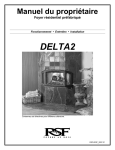
Owner's Manual
Residential Factory Built Fireplace
Operation • Maintenance • Installation
DELTA2
Keep these instructions for future use.
RSF-IID2_2007-01
Dear Customer,
The DELTA2 incorporates technology with elegance to give you a beautiful view of the fire
without compromising on heating efficiency or environmental quality.
We have designed your new DELTA2 to be easy to install, operate and maintain. It is in your
best interest to become familiar with it. Study your manual to be sure that the installation is
correct, then follow the guidelines for operation and maintenance.
We at RSF Woodburning Fireplaces congratulate you on your choice of the DELTA2, and are
confident that you have purchased a fireplace that is simply, the best.
Sincerely,
RSF Woodburning Fireplaces TEAM
March 2006
TABLE OF CONTENTS
SAFETY FIRST
DO'S AND DONT'S
CREOSOTE: FORMATION AND REMOVAL
GENERAL SPECIFICATIONS
THE COMBUSTION CONTROL SYSTEM
OPTIONS
UNIT DIMENSIONS AND CLEARANCES
OPERATION
AIR CONTROL
LIGHTING
THE FIRST FIRE
REFUELING
MAINTENANCE
GENERAL CLEANING
PAINT
GLASS CLEANING
CHIMNEY CLEANING
DISPOSAL OF ASHES
DOOR SEAL ADJUSTMENT
DOOR AND WINDOWS POSITION ADJUSTMENT
GOLD PLATING
DELTA2 Owner's Manual
3
INSTALLATION
3
3
9
MOVING THE DELTA
NAILING BRACKET INSTALLATION
LOCATION
CEILING CLEARANCE
OUTSIDE AIR DUCT
CHIMNEY
CHIMNEY INSTALLATION
OFFSET CHIMNEY
CHASE ENCLOSURE
MASONRY CHIMNEY
FRAMING
HEARTH EXTENSION
BENEATH HEARTH EXTENSION
MANTEL
MANDATORY OPTIONS WITH THE CLEAN FACE
REFRACTORY BRICK INSTALLATION
4
4
4
5
6
6
6
7
7
7
7
7
7
7
8
8
8
9
2
9
9
10
13
13
13
14
15
15
16
17
18
18
18
18
18
LISTING LABEL
20
COMPLETE OPTIONS LIST
21
CONFIGURED OPTIONS LIST
22
EXPLODED DRAWINGS
23
LIMITED WARRANTY
25
RSF Woodburning Fireplaces
SAFETY FIRST
DO'S AND DONT'S
If this fireplace is not properly installed, a house fire could result. For your safety, follow the installation
directions. Contact your local authority having jurisdiction (such as municipal building department, fire
department, fire prevention bureau, etc.) regarding restrictions and installation requirements, and the
need to obtain a permit.
To ANYONE using this fireplace: these DO's and DO NOTs are for your safety.
1. DO read this instruction manual before lighting your first fire.
2. DO burn seasoned wood fuel or densified fuel logs without any additives.
3. To avoid glass breakage, DO NOT slam the fireplace door.
4. DO NOT ever use gasoline, gasoline-type lantern fuel, kerosene, charcoal lighter fluid or similar liquids to
start or freshen up a fire in this fireplace. Keep all such liquids well away from the fireplace while it is in use.
5. DO NOT overfire the fireplace. If you are unable to slow down the burning rate of the fire or if the
chimney connector behind the top louver glows red, you are overfiring the fireplace.
6. DO operate the fireplace with doors either fully closed or fully open with the firescreen. If the door is
left partly open, gas and flame can be drawn out of the fireplace opening, creating both fire and smoke
hazards.
7. If you use the fireplace with the door wide open, install a firescreen (FO-FDFSD) to prevent logs and sparks
from burning your floor. Under no circumstances should the fireplace be used without either the door closed
or the firescreen installed.
8. DO keep all combustible materials (furniture, firewood, etc.) at least 4' away from the front of the fireplace.
9. DO NOT use a fireplace grate or other products not specified for use with this fireplace.
10. DO read the section about MOVING THE DELTA2 before you begin the installation.
NOTE: We strongly recommend that our products be installed and
serviced by professionals who are certified by the National Fireplace
Institute in the U.S. or by Wood Energy Technology Transfer Inc. in
Canada.
CREOSOTE: FORMATION AND REMOVAL
When wood is burned slowly, it produces tar and other organic vapors which combine with the expelled moisture
from the wood to form creosote. The creosote vapors can condense in the relatively cool chimney of a slow
burning fire. When ignited, this creosote makes an extremely hot fire. The chimney should be inspected
periodically during the heating season to see if a creosote build-up has occurred. If a significant layer of creosote
has accumulated (1/4" or more), it should be removed to reduce the risk of chimney fire.
WARNING: BURN DRY WOOD ONLY.
DO NOT BURN:
DRIFTWOOD,
TREATED WOOD,
COAL,
GARBAGE, OR
PLASTIC.
Do not use construction scraps (e.g. 2x4 or plywood scraps) as your only supply of fuel as you can overheat and
seriously damage the fireplace. Do not use more than one wax fuel log (e.g. Duraflame) at a time and only with a
firescreen on the fireplace. Use only firelogs that have been evaluated for fireplace use. In Canada, they should
meet the requirements of ULC/ORD-C127-M1990. Refer to the firelog warnings and caution markings prior to
use.
DELTA2 Owner's Manual
3
RSF Woodburning Fireplaces
GENERAL SPECIFICATIONS
THE COMBUSTION CONTROL SYSTEM
Since the door is sealed, all combustion air must come through the DELTA2's draft control. This control has a
bimetal coil to allow more air when the unit is cold, and less air when the unit is hot, guarding against overheating.
It can be controlled either manually with the lever that is located below the right window frame, or automatically
with an optional electric wall thermostat.
The first few days, it is best to operate the fireplace with the manual control fully open (moved to the right as far
as possible). Just control the fire as you would any normal fireplace, using one or two logs at a time for a smaller
fire, or more logs for more heat. Once you become familiar with operating the fireplace with the control open, you
can start experimenting with lower settings. Remember: when the fireplace is hot, the control will not need as
much movement to reduce the fire as when it is cold. The bimetal coil will already have shut the damper part way.
OPTIONS
There are many different ways you can finish your DELTA2 fireplace no matter what basic unit you have
purchased (black door: FF-DEB2, gold door: FF-DEG2, or pewter door: FF-DEP2). You can choose to install
upper and lower louvers which are available in various colors (black: FO-DLB2, gold: FO-DLG2, or pewter: FODLP2) or no louvers at all (FO-F).
If you choose to install your DELTA2 fireplace without any louvers, you MUST install the Clean Face Option (FOF) along with two Gravity Vent Kits (FO-V). Be aware that you CANNOT install Gravity vent dampers on a Clean
Face DELTA2. Furthermore, we do not recommend that you install any option requiring electricity or a thermal
switch in the fireplace because of the difficulty to access these components after installing the masonry finish on
your fireplace. If you do install electricity or a thermal switch in a Clean Face DELTA2, you may have to break
through the masonry finish at some point in time for maintenance purposes.
To simplify the installation of thin non-combustible materials such as ceramic tile or sliced brick, we have
designed rock retainer kits. They are not designed or required for full brick or stone. With a Louvered DELTA2,
you can choose to leave all the black metal completely exposed, partially exposed or completely covered with
non-combustible material. We offer rock retainer kits to help with the installation of non-combustible materials on
a Louvered DELTA2 (FO-FDKD for perimeter partial coverage and FO-FDKD-1 for complete coverage). We also
have a rock retainer kit for the Clean Face DELTA2 (FO-KD2). Thin materials can also be installed directly on the
face of the DELTA2 using high temperature silicone as glue, without a rock retainer kit.
For increased air circulation and marginally more heat output, you can add the Circulating Internal Blower (FOFDHB5-N) to your Louvered DELTA2 or the Inline Fan (FO-CIF) to your Clean Face DELTA2.
If you have any rooms directly above or adjacent to the room with the fireplace that you would like to heat, you
may want to consider the Gravity Vent Kit (FO-V). The gravity vent distributes hot air to these rooms and requires
no blower to assist its operation.
For constant heat, day and night, you will be surprised by what the Thermostat Option (FO-FDHC4) can do for
you. This option provides you with the necessary parts to automatically control the draft control via a wall
thermostat. It will keep your room temperature as even as though you were heating with oil, gas or electricity,
except you will find wood heat more comfortable.
To maximize the distribution of the heat generated by your DELTA2 fireplace throughout many rooms and
different floors, consider the Central Heat Option. With our Central Heat Blower (FO-FDHB6-1), you can use the
house central heating ducts or dedicated ducts to circulate the fireplace heat to one or many rooms. The Central
Heat Control (FO-FDHC6) will enable automatic control of the Central Heat Blower via a wall thermostat and
thermal switch. The Zone Heat Control (FO-FDHCZ1) along with Zone Damper Kits (FO-FDHCZ2) will provide the
same features as the Central Heat Control but for more than one heating zone. If you wish to install the Central
Heat Blower on a Clean Face DELTA2, you will need the Central Heat Tee (FO-T) that will enable you to connect
the central heat duct along with the left gravity vent on the fireplace.
This fireplace has been specially designed to combine high efficiency with the elegance of a wood burning fire.
Most often you will take advantage of the high efficiency and the control possible with your new DELTA2 wood
burning fireplace. If you would like to enjoy the sight and sound of an open fireplace, or simply have less heat
output in a warmer weather you may wish to install the optional DELTA2 firescreen (FO-FDFSD).
DELTA2 Owner's Manual
4
RSF Woodburning Fireplaces
NOTE: Many options require wiring and/or electricity for their installation. If there is any chance that any of these
options will be installed in the future then suitable wiring should be run during framing. Otherwise, it will be difficult
to install these options later.
Detailed installation instructions are included in the box with each option. These can also be obtained from our
Internet Web Site: www.icc-rsf.com.
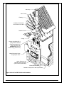
UNIT DIMENSIONS AND CLEARANCES
12"
11 1/2"
4 1/4"
8 1/2"
6 3/4"
9"
12 1/2"
7"
25 1/2"
Refer to Table
1 (J) for
maximum
mantel depth
Refer to Table 1
(K) for minimum
mantel height
above the door
opening
11 3/4"
16 1/2"
11 3/4"
23 3/4"
48 1/4"
3"
5"
5"
19"
29 3/4"
Refer to Table 1
(B) for minimum
distance of side
wall to the
fireplace
Refer to Table 1
(H) for minimum
width of hearth
extension
35"
3"
Non-combustible hearth
extension and spark
guard (refer to Table 1 (I)
and text for particulars)
Refer to Table 1
(G) for minimum
depth of hearth
extension
Figure 1 Unit Dimensions and Clearances
DELTA2 Owner's Manual
5
RSF Woodburning Fireplaces
Table 1 DELTA2 Dimensions and Clearances
A
Distance of combustible material from side, back and top standoffs
B
Minimum distance of side wall to the side of the fireplace
C
Ceiling clearance: from the base of the fireplace to the ceiling
D
0"
(0,0 mm)
11"
(279 mm)
7'
(2,13 m)
Minimum chimney height: minimum total chimney height from fireplace top to
below the chimney rain cap (at sea level and no offset)
12'
(3,66 m)
E
Maximum chimney height: maximum total chimney height from fireplace top to
below the chimney rain cap
40'
(12,19 m)
F
Maximum chimney height supported by the DELTA2 fireplace
16'
(4,88 m)
G
Minimum depth of non-combustible hearth extension: from the front of the
fireplace
16"
(406 mm)
H
Minimum width of non-combustible hearth extension: from sides of the door
opening
8"
(203 mm)
I
Minimum width of the spark guard
23 ¾"
(603 mm)
J
Maximum mantel depth
12"
(305 mm)
K
Minimum height of a combustible mantel above the top of the door opening:
from the highest point of the top of the door opening to below the combustible
mantel (refer to the "Installation: Mantel" section for particulars)
23"
(584 mm)
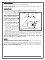
OPERATION
AIR CONTROL
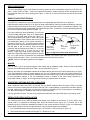
The combustion air control handle is located below the right
window frame (see Figure 2). When the handle is to the far
right, the control is fully open and the fire will burn more quickly.
When the handle is to the far left, it is fully closed and the fire
will burn more slowly.
Independent of the air control handle position, right (open) or
left (closed), the bimetallic coil integrated in the draft control will
cycle through keeping the air control open in the position you
have selected until the bimetallic coil becomes warm enough to
close the draft control to prevent overheating. It will then cool
down until it is cool enough so that the bimetallic coil will open
the draft control back to the position you have selected until it is
warm enough to close the draft control again.
Towards the
left to close
Towards the
right to open
Figure 2 Air Control
LIGHTING
Before starting a fire, make sure to completely open the draft control. It is located below right window frame and
should be pushed completely to the right. Light a fire in the fireplace, starting with paper and kindling only. Then
add three or four pieces of wood, about 3" diameter. After the fire is established, close the door. Never use any
flammable liquids. Once a coal bed is established, add standard cord wood. Leave the draft control open until the
fire is well lit, then adjust it to the level you desire.
WARNING: DO NOT USE A GRATE OR ELEVATE THE FIRE.
DELTA2 Owner's Manual
6
RSF Woodburning Fireplaces
THE FIRST FIRE
You will experience a slow start-up during the first few fires. The refractory bricks contain moisture from
manufacturing and require a few hot fires to evaporate the moisture. While there is still moisture in the bricks, the
bricks will be black with smoke deposits. When the moisture has dissipated, the bricks will turn white. You will
experience a slight odor during the first few fires. This odor comes from curing paint and oil burning off the metal.
Before the first fire, be absolutely sure to wipe off all fingerprints and debris from the gold plating, if you
have chosen this option. The plating cures during this first fire, and the acid from your finger prints will
permanently etch the gold plating.
REFUELING
Fuel wood can be of any species but the fireplace will not burn cleanly or efficiently unless the wood is well
seasoned. Keep your firewood under cover.
The door should be opened slowly to keep smoke from spilling into your room. If you have a problem with
smoke spillage, check to see that all kitchen and bathroom fans have been shut off. They can cause
negative pressure in the house which pulls smoke out of the fireplace.
NOTE: The central heat and internal blowers, if installed, should be shut off during refuelling to prevent smoke
from spilling out of the fireplace.
MAINTENANCE
GENERAL CLEANING
The high heat paint and plating can be cleaned with a soft damp cloth. Use a mild detergent and water. Do not
use abrasive cleaners.
PAINT
You can touch up the face of the DELTA2 with Stove Bright Metallic Black high temperature paint which is
available at most fireplaces dealers. Follow the directions outlined on the spray can. DO NOT attempt to paint the
fireplace while it is still warm. Keep the spray can away from any source of heat or open flame. Ensure that there
is adequate ventilation in the room from the time you start painting until the paint is dry. Stove Bright is available
in a wide range of colors if you want to change the color of your DELTA2.
We recommend that you take the time to protect or remove any item that you do not want to paint such as: the
door glass, the plated door, the fireplace surroundings, etc. The glass can be removed from the door but you will
have to replace the gasket.
GLASS CLEANING
In a controlled combustion firebox, temperatures are not always high enough to keep the glass perfectly clean. A
good hot fire once a day usually cleans off most of the deposits that have accumulated. Remember: the drier the
wood, the cleaner the glass. A word of caution: although heat will not break the glass, impact can. Be careful not
to hit the glass.
WARNING: NEVER CLEAN THE GLASS WITH AN ABRASIVE CLEANER. USE ONLY A CLEANER
RECOMMENDED BY YOUR DEALER. NEVER CLEAN THE GLASS WHILE IT IS HOT, A SERIOUS BURN
CAN RESULT. THERE ARE A NUMBER OF EXCELLENT WOOD STOVE GLASS CLEANERS AVAILABLE
WHICH ARE FAR SUPERIOR TO REGULAR GLASS AND OVEN CLEANERS FOR WOOD STOVE
APPLICATIONS.
CHIMNEY CLEANING
Check the chimney for creosote buildup every week or so until experience shows how often you need to clean it.
A buildup of ¼" or more should be cleaned before more creosote accumulates. Use an 8" round brush. The baffle
in the firebox can be removed to gain access to the flue from below.
To remove the baffle, first remove the secondary air tube. Simply unscrew the secondary air tube on the left side,
DELTA2 Owner's Manual
7
RSF Woodburning Fireplaces
slide the tube toward the right until the left end drops out of its hole. Slide the tube back towards the left to get the
right end out of its hole. To remove the baffle, push up and slide it off the brackets. Replace both the baffle and
the secondary air tube as you removed them and be sure to have the holes on the secondary air tube facing
toward the front.
DISPOSAL OF ASHES
Remove the ashes before they become too deep, before you have a spillage problem when you open the door.
The ashes should be placed in a metal container with a tight-fitting lid. The closed container of ashes should be
placed on a non-combustible floor or on the ground, well away from all combustible materials pending final
disposal. If the ashes are disposed of by burial, or otherwise locally dispersed, they should be retained in the
closed container until all cinders have thoroughly cooled.
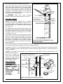
DOOR SEAL ADJUSTMENT
The door hinges on the fireplace can be adjusted for easy installation/removal of the door, and for proper sealing
of the door.
To check for a proper door seal, insert a thin sheet of paper between the door and the front of the fireplace and
latch the door. Pull gently but firmly on the sheet of paper. If the paper either tears or is hard to retrieve, the
adjustment is correct. Repeat this procedure along all sides of the door.
The most important factor for controlling the burning rate of the DELTA2 is a good seal on the door gasket. If the
door gasket is worn or damaged to the point where the seal is not adequate as described above, then remove
and replace the gasket. Replacement kits are available from your RSF dealer.
To insure a proper seal, you need to adjust the tightness of the door against the front of the fireplace as follows:
1. Slightly loosen the four bolts that hold in place the two door hinges to the door, just enough so that the hinges
can be moved when force is applied. You can remove the left side window frame to have an easier access to
the door hinge bolts (refer to the Door and Windows Adjustment section).
2. Close the door and engage the handle while making sure the door is straight.
3. Push the door against the fireplace where the hinges are to seal the gasket.
4. Carefully open the door and tighten all four hinge bolts.
5. Verify the seal with the sheet of paper as described above.
6. Once adjusted for a proper seal, verify that the door can be easily removed and put back on the hinges. You
may have to slightly twist one of the hinges to correct the alignment between the hinges and ease the
installation/removal of the door. You can also lightly grease the hinges pins with the high temperature grease
provided to make the hinges easier to move.
NOTE: An improperly adjusted door seal can have a significant effect on the performance and durability of the
fireplace. A poorly adjusted door can result in reduced efficiency, over firing, excessive wood consumption and
fireplace failure.
DOOR AND WINDOWS POSITION ADJUSTMENT
The door and side window frames can be adjusted to fit nicely together.
To adjust the position of the door, loosen the four bolts that hold in place the hinges to
the fireplace, just enough so that the hinges can be moved when force is applied. Move
the door in the desired direction (left or right, up or down). Retighten all bolts.
"A" Nuts
Each window frame is held in place by two nuts ("A") (see Figure 3) each on a
threaded rod, one at the top and one at the bottom. Both nuts can be accessed through
the firebox. The depth of each window frame is determined by two bolts ("B") (see
Figure 4), one at the top and one at the bottom on the inner side of the window frame
(i.e. towards the door).
To adjust the position of a window frame, loosen both "A" nuts (you may need to
loosen the "B" bolts also), move the window frame, retighten the nuts and bolts.
DELTA2 Owner's Manual
8
Figure 3 Right Side
Window "A" Nuts
RSF Woodburning Fireplaces
To bring the inner side of a window frame out, simply loosen both "A" nuts and then
unscrew both "B" bolts to the level desired and finish by tightening back the "A" nuts.
To bring the inner side of a window frame in, simply screw both "B" bolts and then
tighten both "A" nuts.
GOLD PLATING
If you have gold doors, gold window frames or gold louvers, you will be happy to know
that they will not tarnish. However, they are not scratch resistant. Use only mild soap
and warm water to clean the gold when the surface is cool. The use of any household
cleaner, such as Windex, abrasive cleaners, or any form of acid, may permanently etch
or remove some of the gold plating. Before the first fire, make sure to clean all
fingerprints and other deposits on the gold plating. Since the plating cures during the
first fire, fingerprints and other deposits will permanently etch the gold plating.
"B" Bolts
INSTALLATION
Check with your local authority having jurisdiction (such as municipal building
department, fire department, fire prevention bureau, etc.) regarding restrictions and
installation requirements, and the need to obtain a permit.
Remove the fireplace door. Store it in a safe place until the installation and finishing
work is finished. Side windows must be adequately protected. Be aware that heavy
duty cleaning products or acid solutions will permanently damage the gold plating.
Figure 4 Right Side
Window "B" Bolts
MOVING THE DELTA
Due to the weight of the DELTA2, we recommend you use a furniture dolly and place the DELTA2 as shown in
Figure 5. The DELTA2 weighs 620 lbs. complete and 450 lbs. stripped of all firebricks and baffle. The DELTA2
should be stripped before moving it if possible. Elevate the fireplace and dolly to a 45° angle to move.
NOTE: If using an Eskelera a 2 x 4 will have to be placed between the two forks before using.
NAILING BRACKET INSTALLATION
Before installing your DELTA2, the side nailing brackets need to be assembled as follows:
1. Take the nailing brackets provided with the unit.
2. Remove the four (4) metal screws on each side of the DELTA2 facing.
3. Attach the nailing bracket to the side of the DELTA2 using the metal screws that you removed in Step 2 (see
Figure 6).
NOTE: When using the optional 45° nailing bracket (FO-FDS45) make sure to line up the 45° nailing bracket
with the fireplace to ensure facing will be flush.
Optional 45°
nailing bracket
(FO-FDS45)
Remove
door and
central
louvers
90° nailing strip
Figure 5 Moving the Delta
DELTA2 Owner's Manual
Figure 6 Nailing Bracket Installation
9
RSF Woodburning Fireplaces
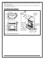
LOCATION
Your DELTA2 fireplace may be installed in many different ways (see Figure 7) without any special floor
reinforcement. We recommend that you take the time to plan your entire installation (fireplace, chimney, and
options) before beginning the actual installation (refer to Figure 8 and Figure 9).
Dimensions of the fireplace along with clearances are shown in Figure 1 and Table 1.
WARNING: IF THIS FIREPLACE IS NOT PROPERLY INSTALLED, A HOUSE FIRE CAN RESULT. FOR
YOUR SAFETY, FOLLOW THE INSTALLATION INSTRUCTIONS AND CLEARANCES. DO NOT PACK
REQUIRED AIR SPACES WITH INSULATION OR OTHER MATERIALS.
1. Note the location of roof and floor joists. Try to choose a location that does not require cutting them.
2. If at all possible, run the chimney up through the inside of the house. If it must be run outside, it should be
enclosed in an insulated enclosure (see Installation: Chase Enclosure). Remember, a cold chimney causes
poor draft.
13 1/2"
49 1/4"
The framing dimensions are larger than required for ease of installation. Examples shown here are for a
Louvered DELTA2. An extra 12" is required either on the left or behind the fireplace of a Clean Face DELTA2
to connect the intake air duct.
Figure 7 Louvered DELTA2 Framing Examples
DELTA2 Owner's Manual
10
RSF Woodburning Fireplaces
Rain Cap
Storm Collar
Flashing
Radiation Shield with a
Storm Collar in the Attic
Radiation Shield
Ceiling
Hearth Extension and
Beneath Hearth Extension
(refer to text for particulars)
Electrical Knock-outs
Outside Air inlet (refer to text for particulars)
Figure 8 Louvered DELTA2 General Installation
DELTA2 Owner's Manual
11
RSF Woodburning Fireplaces
Rain Cap
Storm Collar
Flashing
Radiation Shield with a
Storm Collar in the Attic
Radiation Shield
Ceiling
Gravity Vent Option FO-V
(using flexible insulated
ducting provided by ICC
only): Two FO-V's are
MANDATORY with the
Clean Facing (shown here)
Intake Grill part of Clean
Facing Option FO-F
Hearth Extension and
Beneath Hearth Extension
(refer to text for particulars)
Electrical Knock-outs
Outside Air inlet (refer to text for particulars)
Figure 9 Clean Face DELTA2 General Installation
DELTA2 Owner's Manual
12
RSF Woodburning Fireplaces
CEILING CLEARANCE
Ceiling clearance is the distance from the base of the fireplace to the ceiling.
Under no circumstances should the distance between the ceiling firestop and the base fireplace be less than the
dimension specified in Table 1 (C).
OUTSIDE AIR DUCT
After the fireplace is correctly positioned, connect the outside air inlet to the outside (see Figure 10).
A 4" diameter duct can be used if the total
duct run is less than 25'. For longer runs, use
5" diameter duct. Both 4" and 5" connecting
sleeves are provided with the fireplace.
Fi R S
re F
pl
ac
e
The air inlet should never be less than 5'
below the top of the chimney flue and
must never terminate in attic spaces.
2" Aluminium
Duct Tape
Outside Air
Inlet
Fi RS
re F
pl
ac
e
1. Find a convenient location for the
combustion air duct and outside air inlet.
The outside air inlet can be above or
below floor level.
2. Make a 4 ¼" (5 ¼" if using a 5" diameter
duct) hole in the outside wall of the house.
Push the outside air inlet in from the
outside. Seal the joint between the air
inlet and the outside wall with an
appropriate sealant.
Below Floor
Example
Above Floor
Example
Fi RS
re F
pl
ac
e
Use an insulated aluminium flexible duct rated
at over 200° F. The duct should not exceed
12' vertical rise above the base of the unit.
Insulated Flexible Air Duct
Outside Wall
Figure 10 Outside Air Connection and Installation
Example
3. Place the insulated flexible duct over the round sleeve on the outside air inlet. At both ends, carefully pull
back the insulation and plastic cover, exposing the flexible duct. Then at each end, attach the duct with metal
screws to the inlet and tube. Carefully push the insulation and cover back over the duct. Tape the plastic
cover in place with 2" aluminium duct tape.
CAUTION: WHEN RUNNING THE DUCT AROUND CORNERS, BE SURE TO PREVENT CRIMPING THE
DUCT THAT WOULD RESTRICT THE COMBUSTION AIRFLOW.
CHIMNEY
This fireplace is certified for use with 8" ICC Model EXCEL chimney only. Please refer to Table 1 (D-E) for the
minimum and maximum chimney height permitted with the DELTA2 fireplace.
We recommend that the minimum height be increased by approximately 1' for every 2000' elevation above sea
level. Every 30° or 45° elbow also increases the minimum height by 1' For example, if you are living 6000' above
sea level, your chimney should terminate at least 15' from the top of the fireplace (12' + 3' for the 6000'). See
Table 2 for more precise recommended flue heights.
DELTA2 Owner's Manual
13
RSF Woodburning Fireplaces
Table 2 Minimum Recommended Flue Heights In Feet From The Top Of The Fireplace
Elevation (ft)
0 - 1000
1000 - 2000
2000 - 3000
3000 - 4000
4000 - 5000
5000 - 6000
6000 - 7000
7000 - 8000
8000 - 9000
9000 - 10000
Number Of Elbows
0
12’
12’6”
13’
13’6”
14’
14’6”
15’
15’6”
16’
16’6”
2 x 15°
13’
13’6”
14’
14’6”
15’
15’6”
16’
16’6”
17’
17’6”
4 x 15°
14’
14’6”
15’
15’6”
16’
17’
17’6”
18’
18’6”
19’
2 x 30°
15’
15’6”
16’
17’
17’6”
18’
18’6”
19’
20’
20’6”
4 x 30°
18’
19’
19’6”
20’
21’
21’6”
22’
23’
24’
24’6”
2 x 45°
16’
16’6”
17’
18’
18’6”
19’
20’
20’6”
21’
22’
4 x 45°
20’
20’
21’6”
22’6”
23’
24’
24’6”
25’6”
26’6”
27’
CHIMNEY INSTALLATION
Make sure to read the EXCEL Chimney installation manual concerning requirements for supports, bracing,
anchors, etc. The EXCEL installation manual is available from your dealer or from our web site: "www.iccrsf.com". Refer to Table 1 (F) for the maximum chimney height that can be supported by the top of the fireplace.
WARNING: THE CLEARANCE BETWEEN THE CHIMNEY AND COMBUSTIBLE MATERIAL MUST BE 2"
OR MORE. DO NOT FILL THIS AREA WITH INSULATION.
1. Cut and frame the required holes in the floor(s), ceiling(s) and roof where the chimney will pass through. The
rough opening in the framing is 14" square (the opening can be slightly bigger, up to 14 ½", but NEVER
smaller).
2. From below, install a radiation shield in each floor through which the chimney passes. At the attic level, install
a radiation shield and a storm collar as shown in Figure 11.
WARNING: A RADIATION SHIELD MUST BE INSTALLED AT EACH FLOOR WHERE THE CHIMNEY
PASSES THROUGH.
3. Place the first chimney length on the fireplace.
Secure the chimney length to the fireplace with the
three screws provided.
Rain Cap
2' min.
10'
The chimney must extend at least 3' above its
point of contact with the roof and at least 2' higher
than any wall, roof, or building within 10' of it. If the
chimney is higher than 5' above the roof, it must
be secured using a roof brace.
WARNING:
DO NOT PACK
REQUIRED AIR
SPACES WITH
INSULATION OR
OTHER
MATERIALS
4. Put the roof flashing into place. Seal the joint
between the roof and the flashing with roofing tar.
For sloping roofs, place the flashing under the
upper shingles and on top of the lower shingles.
Nail the flashing to the roof using roofing nails.
In USA: use a vented flashing;
•
In Canada: use a vented flashing, or a roof
radiation shield with a regular flashing.
Storm Collar
in the Attic
2" min.
WARNING:
must be framed to
adequately support
any chimney
supports and roof
assemblies
Radiation
Shield
The chimney
must be enclosed
when it passes through
living spaces: min.
clearance of 2" with
chimney
F e
RS plac
re
Fi
5. Place the storm collar over the chimney and
flashing. Seal it around the chimney with silicone
sealer (DO NOT use roofing tar).
6. Fit the rain cap on the chimney. Secure it tightly in
place.
DELTA2 Owner's Manual
3' min.
NOTE: Openings
If the chimney is enclosed to the roof:
•
Flashing with
Storm Collar
MAJOR RISK
OF FIRE,
LOOSE FILL
INSULATION
MUST NOT GO
ABOVE THE
RADIATION
SHIELD AND
MUST NEVER
COME IN
CONTACT
WITH THE
CHIMNEY
Ceiling
Clearance (see
Table 1 (C))
Figure 11 General Chimney Installation
14
RSF Woodburning Fireplaces
Radiation
Shield
2' min.
1' min.
10'
Rise
Use Offset
Support or
Roof Support
Flashing*
with Storm
Collar & Roof
Radiation
Shield
Offset
Radiation
Shield and
Offset, Roof or
Wall Support
Radiation
Shield
*In USA: use a
vented flashing
3 Metal Screws
in Each Joint
Fi RS
re F
pl
ac
e
*In Canada: use a
vented flashing or a
roof radiation shield
with a regular
flashing
SF ce
R pla
re
Fi
Figure 12 Offset Chimney Installation Example
Insulated Wall
Radiation
Shield
(30° or 45°)
Figure 13 Offset Chimney Through a Wall Example
OFFSET CHIMNEY
An elbow may be installed directly on top of the fireplace if required. See the detailed offset charts in the EXCEL
chimney installation manual. Use the offset option if you need to clear a joist or pass around a cupboard. See
Figure 12 and Figure 13 for examples.
•
•
Maximum offset angle:
•
In USA: 30°;
•
In Canada: 45°.
Maximum number of elbows: four, resulting in two offsets and returns.
Install the fireplace and chimney as described earlier. When you require an elbow, proceed as follows:
1. Install the required elbow. Turn it in the desired direction, and fasten it to the other section with 3 metal
screws at the joints.
2. Install enough lengths to obtain the desired offset. Secure each joint with 3 metal screws.
3. Use another elbow to return the chimney to the vertical direction.
4. Install a roof support, a wall support, or an offset support above each offset to support the weight of the
chimney (elbows are not designed to support the chimney above an offset). The support can be installed
anywhere practical along the vertical course of the chimney as long as it is above the offset.
CHASE ENCLOSURE
If the chimney runs up the outside of the house, we recommend that it be enclosed in a chase structure. The
chase should be constructed in such a way that it is an extension of the home. It should be well insulated between
the footings and the floor of the home to prevent heat loss. If the climate in your area is mild, insulate the chase at
least to the first firestop. If the climate in your area is very cold, insulate the chase to the top to keep the chimney
warmer, increase the draft, and reduce creosote buildup. We also recommend to insulate the ceiling of the chase
just as if it were in the attic space. This will prevent cold air from dropping down through the chase and into the
DELTA2 Owner's Manual
15
RSF Woodburning Fireplaces
room where the fireplace is installed (see Figure 14).
Some local codes require that the walls be insulated,
vapor sealed and sheathed with a fire rated gypsum
board (see Figure 14). We strongly recommend this
procedure for all installations to prevent cold drafts from
originating in the fireplace enclosure. If you follow this
procedure, we recommend that you do not insulate the
wall above the front of the fireplace.
2' min.
10'
Optional
Decorative
Shroud
REMEMBER: Check local codes concerning
installation requirements and restrictions in your area.
MASONRY CHIMNEY
Installing your DELTA2 fireplace with a masonry
chimney still requires using EXCEL chimney from the
top of the fireplace to the wall where it will connect to a
listed liner that will run up inside the masonry chimney
(see Figure 15).
Insulation
Chase liner of fire rated
gypsum board is
recommended (may be
required by local authorities)
Special care is to be taken to make sure that you have a
good solid connection between the EXCEL chimney and
the liner. A masonry adaptor (FO-FDM8) was designed
specifically for that purpose and is available from your
RSF dealer. It will attach to the liner with 3 stainless
steel rivets (provided) and to the EXCEL chimney with 3
screws (provided).
Fi RS
re F
pl
ac
e
The stainless steel liner should be fitted inside the clay
liner all the way to the top of the masonry chimney. It is
not meant to replace the clay liner. You can use either
the EXCEL liner or any other listed liner to ULC-S635,
ULC-S640 or UL-1777.
Radiation
Shield,
with Storm
Collar in
the Attic
Figure 14 Chimney Installed with a Chase
Enclosure Example
After mortaring in place, the connection between the EXCEL chimney and the liner should not be visible in order
to isolate the heat released through the liner from the fireplace enclosure.
As depicted in Figure 15, you must install at least one 18" length of EXCEL chimney after the EXCEL chimney
elbow. The uppermost part of the EXCEL chimney - where it enters the masonry chimney - must be a minimum of
12" from the ceiling.
NOTE: If the ceiling is high enough, you can install one or more EXCEL chimney lengths directly on the
fireplace before the elbow.
WARNING: IF YOU ARE
CONSIDERING USING AN
EXISTING
CHIMNEY,
IT
MUST
FIRST
BE
THOROUGHLY INSPECTED
BY AN AUTHORITY HAVING
JURISDICTION
TO
DETERMINE
THE
FOLLOWING:
12" min. to
combustible ceiling
Clearances as per
NBC or NFPA 211
Metal
Firestop
Mortar
EXCEL chimney
lenght: 18" min.
Liner
Elbow
EXCEL chimney
elbow
Mortar
R
re SF
pl
ac
e
Using an Existing
Masonry Chimney
EXCEL liner or other listed liner to
ULC-S635, ULC-S640 or UL-1777
Masonry Adaptor
FO-FDM8
Fi
If you use a flexible liner,
make sure to be careful when
cleaning to ensure that the
stainless steel flexible liner is
not dislodged in any way.
Figure 15 Connection to a Masonry Chimney
DELTA2 Owner's Manual
16
RSF Woodburning Fireplaces
1. The masonry chimney is well constructed and fully lined, in accordance with Local Building Codes and the
National Building Code of Canada (NBC) or National Fire Protection Association chimney standard (NFPA
211).
2. It has been thoroughly cleaned of any soot or creosote residue and inspected to determine that it is in good
working condition.
3. There is no insulation of any type in contact with the masonry chimney and there is no insulation stuffed
anywhere in the chimney.
4. All the necessary clearances around the masonry chimney, along the complete run of the chimney, are
respected as per NBC or NFPA 211. If the masonry chimney is enclosed in drywall, openings will probably be
required in order to verify clearances at all points.
5. The masonry chimney will only be used for the fireplace and no other appliance.
If major repairs are required to meet the above conditions, a new chimney should be constructed.
To make the hole through the masonry chimney and make the connection to the fireplace, we recommend that
you follow these steps:
1. Sight-in and mark the outline of where the EXCEL chimney will penetrate the masonry chimney.
2. Using a large (¾" - 2") masonry drill bit, drill a hole exactly in the center of the oval outline. With a masonry
hammer and drill, slowly enlarge the hole to the size required. Remember to work from the center out. Be
especially careful with the clay liner behind the brick because three sides of it must stay in place.
3. Bring the stainless steel liner down from the top of the chimney.
If you are using a rigid liner you will need enough room to secure an elbow to it with at least two screws.
If it is difficult to install rigid stainless steel liner in the existing masonry chimney or for a masonry chimney
with less than 10"x10" inside, a listed stainless steel flexible liner can be used along with a flexible/rigid
adaptor (LM-8LAF) available from your RSF dealer.
4. Install the liner elbow and masonry adaptor on the lower end of the liner.
5. Move the fireplace forward enough to install the EXCEL chimney on the fireplace (elbow and length) then
move the fireplace back into position as you connect the masonry adaptor to the EXCEL chimney.
Using a New Masonry chimney
Since the masonry chimney is not build yet, we recommend that you position your fireplace, install the EXCEL
chimney on it and connect to the first length of liner before building the chimney as explained above and shown in
Figure 15 . The liner sections can easily be installed as the layers of brick are being placed. Since this is a new
chimney, we recommend that you build it to the right size so you do not have to ovalize the liner but if you choose
to use a 6"x10" clay liner you will need to ovalize the stainless steel liner to fit into the clay liner.
REMEMBER: The stainless steel liner should be fitted inside the clay liner all the way to the top of the masonry
chimney. It is not meant to replace the clay liner.
FRAMING
Always maintain 2" min.
clearance with chimney
The enclosure walls can be framed with any suitable
materials (2x4 or 2x6 studs, plywood, gypsum board,
etc.). Because of the high heat output potential of the
DELTA2, combustible materials must NOT go closer
to the fireplace than the standoffs, top, back and sides.
Leave the space between
the chimney and the
framing open (no firestop)
You may also completely cover the top of a Louvered
DELTA2 as long as you maintain all fireplace standoff
clearances and the 2" clearances around the chased
chimney. The 2" clearance around the chimney must
be open from the fireplace up to the ceiling. See
Figure 16 for an example of a close clearance
installation.
Always respect the
fireplace standoffs
Figure 16 Close Clearance Installation of a
Louvered DELTA2
DELTA2 Owner's Manual
17
RSF Woodburning Fireplaces
HEARTH EXTENSION
The area immediately in front of the fireplace must be protected by a non-combustible material such as brick, tile,
stone, or slate. Refer to Table 1 (G-H) for the depth and width the hearth protection should extend beyond the
front and both sides of the door opening (see Figure 1). There is no minimum thickness required for the hearth
extension.
BENEATH HEARTH EXTENSION
If the DELTA2 is installed on a non-combustible floor, the spark guard specified below is not required.
Install the spark guard provided (5" x 36" piece of sheet metal) halfway under the fireplace and halfway under the
hearth extension and centered on the door opening. The spark guard will extend 2½" beneath the fireplace. This
will make certain that sparks cannot lodge in this area and start a fire. If necessary, the provided spark guard can
be cut to the minimum width specified in Table 1 (I).
If you are preparing a raised installation, you will need
RSF
a custom made spark guard, either a "Z" shaped spark
Fireplace
guard or a right angle spark guard (see Figure 17).
The Z-shaped spark guard must be used if the height
NonCombustible
between the bottom of the fireplace and the top of the
Flooring
2 1/2" or less
non-combustible flooring of the hearth extension is
More than 2 1/2"
less than or equal to 2 ½". The height of the Z-shaped
spark guard must equal the distance between the floor
NonZ-Shaped Spark
Right Angle
and the base of the unit and go under the hearth
Combustible
Guard (not
Spark Guard
extension and the fireplace by at least 2½". If the unit
Flooring
provided)
(not provided)
is installed higher than 2 ½" from the top of the
flooring, a right angle spark guard is necessary. The
Figure 17 Special Custom-made Spark Guard
sides of the right angle spark guard should be at least
2½" x 2½" and must be covered with non-combustible material. Any custom-made spark guard must have the
minimum width specified in Table 1 (I), and be installed centered on the door opening.
NOTE: Custom-made spark guards are not supplied.
MANTEL
Refer to Table 1 (J) for the maximum depth of the mantel and its installation height. Wood or other combustible
mantels must be placed as specified in Table 1 (K) and illustrated in Figure 1.
Masonry and other non-combustible mantels can be placed directly above the top of the fireplace facing or higher.
If the noncombustible mantel is located between the top of the fireplace facing and the specified height for a
combustible mantel, then the wall portion between the top of the fireplace facing and the mantel must be covered
in non-combustible material. If the non-combustible mantel is located at the same height allowed for a
combustible mantel, or higher, then no special wall covering is required below the mantel.
MANDATORY OPTIONS WITH THE CLEAN FACE
When installing a Clean Face (FO-F) on your DELTA2, you MUST install the intake duct (part of FO-F) to provide
sufficient air to the unit along with two Gravity Vent Kits (FO-V, sold separately) to provide an evacuation path for
the heat. Neglecting to install either one of these will result in overheating of the unit and may put your safety at
risk. Refer to each option's installation instructions for particular details.
Use only genuine RSF parts. The use of any substitutes will decertify the system and may put your safety at risk.
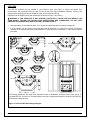
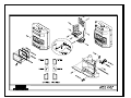
REFRACTORY BRICK INSTALLATION
The refractory bricks for the DELTA2 fireplace are placed in the fireplace at the factory. If, for any reason, they
should need to be replaced the following order should be observed (see Figure 18). To remove any of the
refractory bricks, just follow the installation procedure in the reverse sequence. Refer to Figure 18 to adequately
identify which refractory brick is the right and which is the left at each step of the installation.
1. First, install both bottom refractory bricks (right 11.5.D and left 11.6.D) as shown in Figure 18.
2. Then install both back refractory bricks (right 11.1.D and left 11.2.D).
DELTA2 Owner's Manual
18
RSF Woodburning Fireplaces
3. Continue by installing both side refractory bricks (right
11.3.D and left 11.4.D). If the refractory bricks on the back
and sides do not fit immediately into position as in the
diagram they should not be forced. The refractory bricks
can only be fitted into place as they were designed to do.
4. The last three refractories should be placed in front from
left to right looking at the fireplace (left 11.8.D, middle
11.9.D and right 11.7.D).
11.4.D
11.2.D
11.1.D
11.6.D
11.8.D
11.3.D
11.9.D
11.7.D
11.5.D
Figure 18 Refractory Bricks Installation
DELTA2 Owner's Manual
19
RSF Woodburning Fireplaces
DELTA2 Owner's Manual
23 IN. / 584 MM FROM DOOR OPENING
0 IN. / 0 MM TO SPACERS
HEIGHT OF MANTLE
UNIT TOP, BACK, SIDES AND BOTTOM
20
WOODBURNING FIREPLACES
REPLACE GLASS ONLY WITH 5MM CERAMIC GLASS. OPERATE ONLY WITH FIREBRICK IN PLACE. FOR USE
WITH SOLID WOOD FUEL ONLY. DO NOT OVERFIRE UNIT. WARNING: THIS FIREPLACE HAS NOT BEEN
TESTED WITH AN UNVENTED GAS LOG SET. TO REDUCE RISK OF FIRE OR INJURY, DO NOT INSTALL AN
UNVENTED GAS LOG SET INTO THE FIREPLACE.
REFER TO MANUFACTURER'S INSTALLATION AND OPERATING INSTRUCTIONS FOR OPTIONAL
COMPONENTS:
FANS, FIRECREEN, GRAVITY VENT SYSTEM (WITH AUTHORISED LOUVERS), CENTRAL HEATING
ACCESSORIES.
COMPONENTS REQUIRED FOR INSTALLATION:
CHOICE OF DOOR.
USE 4 IN. OR 5 IN. (102 OR 130MM) DIAMETER FLEXIBLE DUCT AND COMBUSTION AIR INLET ASSEMBLY.
USE THE ICC MODEL 8 IN. (203 MM) EXCEL CHIMNEY AND LISTED COMPONENTS AS PER INSTALLATION
INSTRUCTIONS.
TWO GRAVITY VENT SYSTEMS ARE MANDATORY WITH THE OPTIONAL CLEAN FACING.
ONE AIR AMBIENT INLET IS MANDATORY WITH THE OPTIONAL CLEAN FACING.
COMBUSTIBLE MATERIALS ARE NOT PERMITTED ON FACE OF UNIT. COMBUSTIBLE FLOOR MUST BE
PROTECTED AS SPECIFIED IN THE INSTALLATION INSTRUCTION MANUAL.
11 IN. / 280 MM FROM DOOR OPENING
SIDEWALL, SIDE FACING
MINIMUM CLEARANCES TO COMBUSTIBLE MATERIALS
INSTALL AND USE ONLY IN ACCORDANCE WITH THE MANUFACTURER'S INTALLATION AND
OPERATING INSTRUCTIONS. DO NOT OBSTRUCT COMBUSTION AIR INLET. DO NOT USE A
FIREPLACE INSERT OR OTHER PRODUCTS NOT SPECIFIED FOR USE IN THIS PRODUCT. OPERATE
WITH DOORS FULLY OPEN OR FULLY CLOSED.
FOYER PRÉFABRIQUÉ HOMOLOGUÉ
MODÈLE: DELTA
MIS A L'ESSAI SELON LES NORMES
UL-127 / ULC-S610 / ULC-S627
23 PO. / 584 MM DE L'OUVERTURE DE LA PORTE
0 PO. / 0 MM DES CALES
11 PO. / 280 MM DE L'OUVERTURE DE LA PORTE
19990002
FOYERS AU BOIS
LE REMPLACEMENT D'UNE VITRE DOIT SE FAIRE AVEC UNE VITRE CÉRAMIQUE DE 5MM D'ÉPAISSEUR
SEULEMENT. OPÉRER SEULEMENT AVEC LES PIERRES RÉFRACTAIRES EN PLACE. POUR UTILISATION AVEC DU
BOIS SEULEMENT. NE PAS SURCHAUFFER L'APPAREIL. AVERTISSEMENT: CE FOYER N'A PAS ÉTÉ TESTÉ AVEC
UNE BÛCHE À GAZ SANS ÉVENT. POUR RÉDUIRE LES RISQUES DE FEU ET DE BLESSURES, NE PAS INSTALLER DE
BÛCHE À GAZ SANS ÉVENT DANS CE FOYER.
VOIR LES INSTRUCTIONS D'INSTALLATIONS DU MANUFACTURIER POUR LES COMPOSANTES OPTIONNELLES:
SOUFFLERIES, ÉCRAN PARE-ÉTINCELLES, SYSTÈME D'ÉVENT PAR GRAVITÉ (AVEC PERSIENNES AJOURÉES
AUTORISÉES), ACCESSOIRES DE CHAUFFAGE CENTRAL.
PIÈCES REQUISES POUR L'INSTALLATION:
PORTE AU CHOIX.
TUYAU FLEXIBLE DE 4" OU 5" (102 OU 130MM) DIA. ET PRISE D'ENTRÉE D'AIR.
UTILISER UNE CHEMINÉE EXCEL 8" (203 MM) DE DIAMÈTRE DE ICC SELON LES INSTRUCTIONS
D'INSTALLATION.
DEUX SYSTÈMES D'ÉVENTS DE GRAVITÉ SONT OBLIGATOIRES AVEC L'OPTION DE FAÇADE NEUTRE.
UN SYSTÈME D'ENTRÉE D'AIR AMBIANT EST OBLIGATOIRE AVEC L'OPTION DE LA FAÇADE NEUTRE.
LES MATÉRIAUX COMBUSTIBLES NE SONT PAS PERMIS SUR LA FAÇADE DE L'APPAREIL. UN PLANCHER
COMBUSTIBLE DOIT ÊTRE PROTÉGÉ SUIVANT LES SPÉCIFICATIONS DU LIVRET D'INSTRUCTIONS.
DESSUS, ARRIÈRE , CÔTÉS ET BASE DE
L'APPAREIL
HAUTEUR DU MANTEAU
MUR DE CÔTÉ, FAÇADE-CÔTÉ
DÉGAGEMENTS MINIMAUX AUX MATIÈRES COMBUSTIBLES
INSTALLER ET UTILISER SELON LES INSTRUCTIONS D'INSTALLATION ET DE FONCTIONNEMENT DU
MANUFACTURIER. NE PAS OBSTRUER L'ENTRÉE D'AIR COMBUBURANT. N'UTILISEZ PAS D'ENCASTRABLE
OU AUTRES PRODUITS NON SPECIFIÉS POUR UTILISATION AVEC CE PRODUIT. FAIRE FONCTIONNER
LE FOYER AVEC LA PORTE COMPLÈTEMENT OUVERTE OU FERMÉE.
SERIAL NO. / NO DE SÉRIE
DO NOT REMOVE THIS LABEL / NE PAS ENLEVER CETTE ÉTIQUETTE
LISTED FACTORY BUILT FIREPLACE
MODEL: DELTA
TESTED TO: UL-127 / ULC-S610 / ULC-S627
LISTING LABEL
RSF Woodburning Fireplaces
COMPLETE OPTIONS LIST
Electricity
required
9
FO-CIF
Inline Fan
FO-D
Gravity Vent Damper
FO-DLB2
Delta Louver Kit - Black
FO-DLG2
Delta Louver Kit - Gold
FO-DLP2
Delta Louver Kit - Pewter
FO-DUCT5
Insulated Duct 5 feet
FO-F
Clean Face – Delta2 & Opel2
FO-FDFSD
Delta Firescreen
FO-FDHB5-N
Blower - Internal
FO-FDHB6-1
Blower - Central Heat
FO-FDHC4
Thermostat Kit
FO-FDHC6
Central Heat Control
FO-FDHC6-1
Back Draft Damper
FO-FDHCZ1
Zone Heat Control
FO-FDHCZ2
Zone Damper Kit
FO-FDKD
Rock Retainer Kit
FO-FDKD-1
Rock Retainer Kit (full)
FO-FDM8
Masonry Chimney Adapter 8”
FO-FDS45
45° Nailing Bracket (Delta & Delta2)
FO-FDGRK7
Gasket Replacement Kit (Delta & Delta2)
FO-KD2
Rock Retainer Kit for Clean Face Delta2
FO-T
Central Heat Tee Option
FO-V
Gravity Vent Kit
DELTA2 Owner's Manual
9
9
9
9
9
9
21
RSF Woodburning Fireplaces
CONFIGURED OPTIONS LIST
Clean Face DELTA2
Required
Clean Face Option
Optional
Not available
FO-F
Gravity Vent Kit
FO-V (2)
Delta - Rock Retainer Kit for Clean Face
FO-KD2
Inline Fan
FO-CIF
Central Heat Tee Option
FO-T
Firescreen
FO-FSD2
Thermostat kit (must be installed before facing
and must be accessible for servicing)
FO-FDHC4
Blower - Central Heat
FO-FDHB6-1*
Blower (internal fan)
FO-FDHB5-N
Gravity Vent Damper
FO-D
Louvered DELTA2
Required
Louvers – Black
or
FO-DLB2
Louvers – Gold
or
FO-DLG2
Louvers – Pewter
Optional
Not available
FO-DLP2
Delta - Rock Retainer Kit for Louver option
FO-FDKD
Delta - Rock Retainer Kit for Louver option
FO-FDKD-1
Blower - Central Heat
FO-FDHB6-1*
Thermostat kit
FO-FDHC4
Blower (internal fan)
FO-FDHB5-N
Firescreen
FO-FSD2
Gravity Vent Kit
FO-V (1 or 2)
Gravity Vent Damper
FO-D
Delta - Rock Retainer Kit for Clean Face
FO-KD2
Inline Fan
FO-CIF
* Possible add-ons: FO-FDHC6, FO-FDHCZ1, FO-FDHCZ2
DELTA2 Owner's Manual
22
RSF Woodburning Fireplaces
EXPLODED DRAWINGS
2006-JUIL
DELTA2 Owner's Manual
23
RSF Woodburning Fireplaces
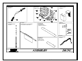
99.09.05.D
DOOR HANDLE
ASSEMBLY
99.10.04.D
LOUVER HARDWARE
ASSEMBLY
99.12.01.D
TERMINAL BLOCK
ASSEMBLY
99.11.01.D
REFRACTORY
COMPLETE SET
99.10.05.D
LOUVER BLOCK PLATE ASSEMBLY
(TOP CENTER LOUVER ONLY)
10.1.D BLACK
10.11.D GOLD
10.21.D PEWTER
CENTRAL LOUVER FIN
10.2.D BLACK
10.12.D GOLD
10.22.D PEWTER
SIDE LOUVER FIN
99.09.04.D
HINGE ASSEMBLY
99.06.02.D
CHAIN & PENDANT
ASSEMBLY
2006-NOV
DELTA2 Owner's Manual
24
RSF Woodburning Fireplaces
LIMITED WARRANTY
30 Years Limited Warranty
All RSF Woodburning Fireplaces models are warranted against defects in material and workmanship for a
period of 30 years, subject to the following conditions:
During the first year RSF Woodburning Fireplaces will repair or replace, at our option, any parts which upon
examination by an authorized RSF Woodburning Fireplaces representative, are found to be defective, except
the parts listed in the EXCLUSIONS portion of this warranty. RSF Woodburning Fireplaces will also pay
reasonable labor costs for the repair work.
During the second through fifth years RSF Woodburning Fireplaces will repair or replace, at our option, any
parts which upon examination by an authorized RSF Woodburning Fireplaces representative, are found to be
defective, except the parts listed in the EXCLUSIONS portion of this warranty. RSF Woodburning Fireplaces
shall not be responsible for any labor costs associated with this repair work.
During the sixth through thirtieth years RSF Woodburning Fireplaces will provide replacement parts, if available,
at 50% of the published retail price, except for the parts listed in the EXCLUSIONS portion of this warranty. RSF
Woodburning Fireplaces shall not be responsible for any labor costs associated with this repair work.
EXCLUSIONS:
•
Electrical components are warranted for one year only.
•
Glass and plating.
•
Damage due to normal wear and tear, such as paint discoloration, worn gaskets, eroded or cracked refractory
components.
•
Repairs or replacements necessitated by vandalism, neglect, abuse, over-firing, improper fuel or fuel loads, or
failure to adequately service the unit, as stated in the owner’s manual.
•
Repairs or replacements (particularly charges for travel and labor) not authorized by RSF Woodburning
Fireplaces in advance.
LIMITATIONS:
•
All items found to be defective will be replaced or repaired upon return of the defective part to an authorized
RSF Woodburning Fireplaces dealer. RSF Woodburning Fireplaces will not be responsible for freight
costs related to shipping replacement parts.
•
Any complete fireplace, or part thereof, that is replaced or serviced under this warranty, will be warranted for a
period not exceeding the remaining term of the original warranty.
•
This warranty is not transferable.
•
This warranty does not apply to damage to the appliance while in transit.
•
This warranty does not apply if the installation does not conform to the installation requirements in the owner’s
manual.
RSF Woodburning Fireplaces is free of liability for any damages caused by the appliance, as well as material
and labor charges incurred in the removal or re-installation of any RSF Woodburning Fireplaces fireplace under
this warranty. Incidental or consequential damages are not covered by this warranty.
The remedies set forth herein are exclusive, and the liability of the seller shall not exceed the price of the fireplace
or part thereof upon which the liability is based.
This warranty is expressly in lieu of all other warranties expressed or implied, including the warranties of
merchantability and fitness for use and all other obligations or liabilities on the part of RSF Woodburning
Fireplaces.
DELTA2 Owner's Manual
25
RSF Woodburning Fireplaces