1
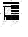
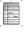
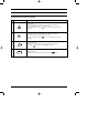
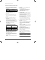
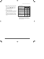
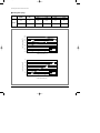
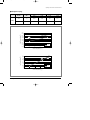
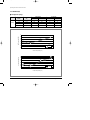
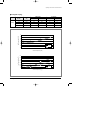
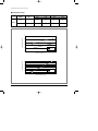
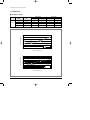
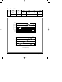
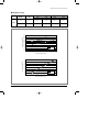
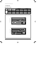
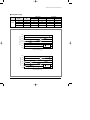
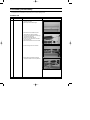
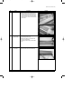
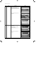
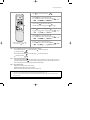
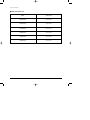
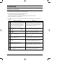
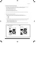
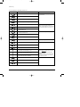
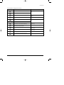
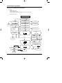
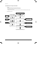
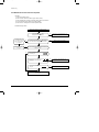
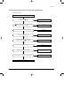
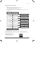
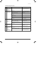
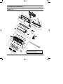
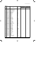
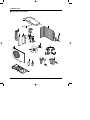
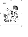
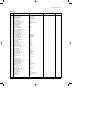
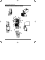
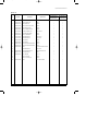
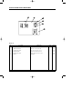
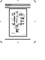
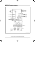
DB98_16045A(1)_co
12/9/03 1:33 PM
Page 3
MULTI AIR CONDITIONER
INDOOR UNIT
OUTDOOR UNIT
MH18AP1(P2)-09
MH19AP1(P2)-07
MH19AP1(P2)-12
MH24AP1(P2)-12
MH26AP1(P2)-07
MH26AP1(P2)-12
MH18AP1(P2)X
SERVICE
AIR CONDITIONER
MH19AP1(P2)X
MH24AP1(P2)X
MH26AP1(P2)X
Manual
CONTENTS
11. Product Specifications
12. Operating Instructions &
Technical Document
13. Disassembly and Reassembly
14. Refrigerating Cycle Diagram
15. Set Up the Model Option
16. Troubleshooting
17. Exploded Views and Parts List
18. PCB Diagram
19. Wiring Diagram
10. Schematic Diagram
DB98_16045A(1)_1
12/9/03 1:35 PM
Page 1
1. Product Specifications
1-1 Table
MH18AP1(P2)
Model
Item
OUTDOOR UNIT
MH18AP1(P2)-09
MH18AP1(P2)X
MH19AP1(P2)-07
MH19AP1(P2)-12
MH19AP1(P2)X
WALL-MOUNTING MULTI SPLIT
2.65 / 2.78
2.05 / 2.25
1 Unit(B/C)
2.65 / 2.78
3.51 / 3.60
5.30 / 5.56
5.56 / 5.85
2 Unit(B+C)
-
-
3 Unit(A+B+C)
-
Dehumidifying(A+B/C)
Noise
Cooling / Heating
Power
kW
-
\/h
1.1+1.1
-
1.0+1.4
-
dB
39 / 39
57 / 57
(–07):36 / 36,
(–12):43 / 43
57 / 57
1 / 220-240V~ / 50
ø/V/Hz
1 / 220-240V~ / 50
Power Consumption
1 Unit(A)
1,020 / 980
870 / 780
(Cooling/Heating)
1 Unit(B/C)
1,020 / 980
1,270 / 1,420
1,940 / 1,900
2,100 / 2,120
2 Unit(B+C)
-
-
3 Unit(A+B+C)
-
-
4.5 / 4.4
3.9 / 3.5
4.5 / 4.4
5.7 / 6.3
8.6 / 8.4
9.3 / 9.4
2 Unit(B+C)
-
-
3 Unit(A+B+C)
-
-
30
30
2 Unit(A+B/C)
Power
INDOOR UNIT
WALL-MOUNTING MULTI SPLIT
2 Unit(A+B/C)
Performance
OUTDOOR UNIT
1 Unit(A)
Type
Cooling/Heating
MH19AP1(P2)
INDOOR UNIT
Operating Current
1 Unit(A)
(Cooling/Heating)
1 Unit(B/C)
2 Unit(A+B/C)
Starting Current(Cooling/Heating)
Outer Dimension
mm
795 x 258 x 179
880 x 638 x 310
795 x 258 x 179
890 x 285 x 179
880 x 638 x 310
inch
313 x 102 x 70
346 x 251 x 122
313 x 102 x 70
350 x 112 x 70
346 x 251 x 122
kg
7.5
59.5
7.5 / 8.5
60
WxHxD
Liquid
OD(mm)xL(m)
Gas
Drain Hose
Size
A
A
Weight
Refrigerant Pipe
W
ø9.52 x 7.5
ø9.52 x 7.5
ø17
-
ø17
ROTARY
-
ROTARY
G4A097JU1EP
-
G4A080JU1EP
G8C124JU1EL
Model Name
-
Capacitor
-
35 / 35
-
30 / 35
Motor
-
INDUCTION MOTOR
-
INDUCTION MOTOR
Type(Model)
Rated Output(A+B/C)
W
Type
Blower
ø6.35 x 7.5
ID(mm)
Type
Compressor
ø6.35 x 7.5
Motor
Type
Rated Input
W
-
925+925
-
820+1,060
CROSS-FAN
PROPELLER
CROSS-FAN
PROPELLER
RESIN
STEEL
RESIN
STEEL
35
100
(–07):35 / (–12):35
100
2ROW 14STP
2ROW 10STEP
2ROW 12STEP
2ROW 10STEP
2ROW 18STEP
2ROW 10STEP
Heat Exchanger
Refrigerant Control Unit
A,B-UNIT:CAPILLARY TUBE
A,B-UNIT:CAPILLARY TUBE
Refrigerant to Change(R410A)
A-UNIT:770g / B-UNIT:770g
A-UNIT:620g / B-UNIT:1,080g
Additional Refrigerant
(Refrigerant must be added if the piping)
Protection Device
Standard Conditions
Samsung Electronics
g/m
20(A,B-UNIT)
-
18(A-UNIT)
25(B-UNIT)
-
-
RAC12131-9622
-
RAC12126-9622
RAC12128-9622
ISO R5151 STANDARD
ISO R5151 STANDARD
1
DB98_16045A(1)_1
12/9/03 1:35 PM
Page 2
Table(cont.)
MH24AP1(P2)
Model
Item
Type
Cooling/Heating
OUTDOOR UNIT
INDOOR UNIT
OUTDOOR UNIT
MH24AP1(P2)-12
MH24AP1(P2)X
MH26AP1(P2)-12
MH26AP1(P2)-07
MH26AP1(P2)X
WALL-MOUNTING MULTI SPLIT
WALL-MOUNTING MULTI SPLIT
3.51 / 3.51
3.51 / 3.65
3.8 / 3.8
2.05 / 2.06
7.02 / 7.6
5.56 / 5.71
1 Unit(A)
1 Unit(B/C)
2 Unit(A+B/C)
Performance
kW
2 Unit(B+C)
-
4.1 / 4.12
3 Unit(A+B+C)
-
7.61 / 7.77
Dehumidifying(A+B/C)
Noise
Cooling / Heating
\/h
1.4+1.4
-
1.4+1.0 / 1.0
-
dB
42 / 42
60 / 60
(–12):43 / 43,
(–07):36 / 36
60 / 60
1 / 220-240V~ / 50
1 / 220-240V~ / 50
Power Consumption
1 Unit(A)
1,280 / 1,280
1,370 / 1,310
(Cooling/Heating)
1 Unit(B/C)
1,280 / 1,280
1,590 / 1,720
2, 560 / 2, 560
2,780 / 2,840
2 Unit(B+C)
-
1,640 / 1,490
3 Unit(A+B+C)
-
2,900 / 2,630
6.0 / 5.8
Power
ø/V/Hz
2 Unit(A+B/C)
Power
W
Operating Current
1 Unit(A)
5.7 / 5.7
(Cooling/Heating)
1 Unit(B/C)
5.7 / 5.7
7.2 / 7.8
11.4 / 11.4
12.4 / 12.7
2 Unit(A+B/C)
-
7.5 / 6.9
3 Unit(A+B+C)
-
13.0 / 11.7
Outer Dimension
mm
790 x 245 x 165
1,000 x 790 x 310
inch
311 x 96 x 65
394 x 311 x 122
350 x 112 x 70
313 x 102 x 70
394 x 311 x 122
Liquid
kg
7.7
69
8.5 / 7.5
71
OD(mm)xL(m)
Gas
ø9.52 x 7.5
ø17
ø17
ROTARY
-
ROTARY
G8C124JU1EL
-
G8C124JU1EL
G8C150JU1EH
-
Capacitor
-
35 / 35
-
35 / 35
Motor
-
INDUCTION MOTOR
-
INDUCTION MOTOR
Type(Model)
Motor
W
Type
Rated Input
W
Refrigerant Control Unit
Refrigerant to Change(R410A)
Additional Refrigerant
(Refrigerant must be added if the piping)
-
1,060+1,060
-
1,060+1,250
CROSS-FAN
PROPELLER
CROSS-FAN
PROPELLER
RESIN
STEEL
RESIN
STEEL
35
150
(–12):35 / (–07):35
150
2ROW 18STEP
2ROW 12STEP
2ROW 10STEP
2ROW 16STEP
2ROW 20STEP
2ROW 12STEP
Heat Exchanger
Standard Conditions
ø9.52 x 7.5
Model Name
Rated Output(A+B/C)
Protection Device
ø6.35 x 7.5
-
Type
Blower
1,000 x 790 x 310
ø6.35 x 7.5
ID(mm)
Type
Compressor
40
890 x 285 x 179
795 x 258 x 179
WxHxD
Drain Hose
Size
35
A
Weight
Refrigerant Pipe
A
2 Unit(B+C)
Starting Current(Cooling/Heating)
2
MH26AP1(P2)
INDOOR UNIT
g/m
A,B-UNIT:CAPILLARY TUBE
A-UNIT:CAPILLARY TUBE
B,C-UNIT:ELEC.EXPANSION V/V
A-UNIT:1,000g / B-UNIT:1,000g
A-UNIT:910g / B-UNIT:1,290g
16(A,B-UNIT)
-
16(A-UNIT)
21(B+C-UNIT)
-
-
RAC12128-9622
-
RAC12128-9622
RAC12122-9622
ISO R5151 STANDARD
ISO R5151 STANDARD
Samsung Electronics
DB98_16045A(1)_1
12/9/03 1:35 PM
Page 3
MEMO
Samsung Electronics
3
DB98_16045A(1)_1
12/9/03 1:35 PM
Page 4
2. Operating Instructions & Technical Document
2-1 Operating Instructions
2-1-1 The Feature of Key in remote control
No
1
NAMED OF KEY
FUNCTION OF KEY
(On/Off)
On/Off button.
Press the
button to stop or run the air conditioner.
(UP)
Temperature adjustment button(UP).
To increase the temperature by the pressing the temperature button.
(DOWN)
Temperature adjustment button(DOWN).
To decrease the temperature by the pressing the temperature button.
2
Mode selection button.
Each time you press this button
Mode is changed in the following order
3
: Auto Mode
: Fan Only
: Cool Mode
: Heat Mode
: Dry Mode
Fan speed adjustment button.
Each time you press this button, FAN SPEED is changed in the following order.
4
Low
Medium
High
Automatic(rotated :
4
)
5
Swing button.
It adjusts the airflow to upward and downward.
6
Turbo button.
The air conditioner cools or heats the room as quickly as possible.
After 30minutes, the air conditioner is reset automatically to the previous mode.
7
Sleep button.
The sleep timer can be used when you are cooling or heating your room to switch the
air conditioner off automatically after a period of 6 hours.
Samsung Electronics
DB98_16045A(1)_1
12/9/03 1:35 PM
Page 5
The Feature of Key in remote control(cont.)
No
NAMED OF KEY
8
FUNCTION OF KEY
On Timer button.
The On Timer enables you to switch on the air conditioner automatically after
a given period of time that is from 30 minutes to 24 hours.
To set the operating time, press the
time display.
9
Off Timer button.
The Off Timer enables you to switch off the air conditioner automatically after
a given period of time that is from 30 minutes to 24 hours.
To set the operating time, press the
time display.
10
Samsung Electronics
button one or more times until the required
Timer Set/Cancel button.
After setting On Timer or Off Timer, press the
And press the
11
button one or more times until the required
button to set it completely.
button again to cancel On Timer or Off Timer set.
Digital On/Off button.
If you want to turn off the display during operation press the
button.
5
DB98_16045A(1)_1
12/9/03 1:35 PM
Page 6
Operating Instructions & Technical Document
2-1-2 Name & Function of Key in remote control
1.
AUTO MODE : In this mode, operation mode(COOL,
HEAT) is selected automatically by the room temperature
of initial operation.
Room Temp
Operation Type
Tr≥ 21°C+∆T
Cool Operation (Set Temp:24˚C+∆T)
21°C +∆T>Tr
Heat Operation (Set Temp:22˚C+∆T)
∆T= -1°C, -2°C, 0°C, +1°C, +2°C
∆T is controlled by setting temperature up/down key of
remote control
2.
COOL MODE : The unit operates according to the
difference between the setting and room temperature.
(18°C~30°C)
3.
HEAT MODE : The unit operates according to the
difference between the setting and room temperature.(16°C~30°C)
*Prevention against cold wind : In order to prevent the
cool air from flowing out at the heat mode, the indoor fan
does not operate or operates very slowly in the
following cases. At this time, the indoor heat exchanger
will be preheating.
- For 3~5 minutes after the initial operation
- For deicing operation
- The operation of an indoor fan in accordance with
the temperature of an indoor heat exchanger
The temperature of
indoor heat exchanger
DRY MODE : Has 3 states, each determined by room
temperature.
The unit operates in DRY mode.
*Compressor ON/OFF Time is controlled compulsorily
(can not set up the fan speed, always breeze).
*Protective function : Low temperature release.
(Prevention against freeze)
5.
TURBO MODE : This mode is available in AUTO, COOL,
HEAT, DRY, FAN MODE.
When this button is pressed at first, the air conditioner is
operated "powerful" state for 30 minutes regardless of the
set temperature, room temperature.
When this button is pressed again, or when the operating
time is 30 minutes, turbo operation mode is canceled and
returned to the previous mode.
*But, if you press the TURBO button in DRY or FAN
mode that is changed with AUTO mode automatically.
6.
SLEEP MODE : Sleep mode is available only in COOL or
HEAT mode.
The operation will stop after 6 hours.
*In COOL mode : The setting temperature is automatically raised by 1°C each 1hour When the temperature
has been raised by total of 2°C, that temperature is
maintained.
*In HEAT mode : The setting temperature is automatically
dropped by 1°C each 1hour.
When the temperature has been dropped by total of 2°C,
that temperature is maintained.
7.
FAN SPEED : Manual (3 step), Auto (4 step)
Fan speed automatically varies depending on both the
difference between setting and the room temperature.
8.
COMPULSORY OPERATION :
For operating the air conditioner without the remote
control.
*The air conditioner starts up in the most suitable mode
for the room temperature:
Indoor fan speed
below 28˚C
off
28˚C~below 34˚C
LL Speed
34˚C~below 40˚C
L Speed
above 40˚C
Setting Speed
*High temperature release function : It is a function to
detect an outdoor overload by the sensor of an indoor
heat exchanger and to turn the outdoor fan or the
compressor ON/OFF for safety.
*Deice : Deicing operation is controlled by indoor unit's
heat exchanger temperature and accumulating time of
compressor's operation.
Deice ends by sensing of the processing time by deice
condition.
6
4.
Room Temperature
Operating Mode
Less than 21˚C
Heat
22˚C approx.
21˚C or above
Cool
24˚C approx.
Temperature Setting
Samsung Electronics
DB98_16045A(1)_1
12/9/03 1:35 PM
Page 7
Operating Instructions & Technical Document
9.
SWING : BLADE-H is rotated vertically by the stepping
motor.
*Swing Set : Press the
button under the remote
control is displayed on LCD the
and the blades
move up and down. If the one more time press the
button, blades location is stop.
10. SETTING THE ON/OFF TIMER. :
*ON TIMER : The On Timer enables you to switch on the
air conditioner automatically after a given period of time.
You can set the period of time from 30 minutes to 24
hours.
*OFF TIMER : The Off Timer enables you to switch off
the air conditioner automatically after a given period of
time. You can set the period of time from 30 minutes to
24 hours.
11. SELF DIAGNOSIS
Error Mode
DISPLAY 7-SEGMENT
Remark
Operation Off Operation On
Indoor unit room temperature sensor
error (open or short)
OFF
E1
Indoor unit heat exchanger
temperature sensor error(open or short)
OFF
E2
Indoor FAN MOTOR error :
Keep the RPM value 450 below for
15 seconds
OFF
E3
EEPROM error
OFF
E6
All lamp
blinking
All lamp
blinking
Error in option
In case of No option set-up
In case of option data error
12. BUZZER SOUND : Whenever the On/Off button is
pressed or whenever change occurs to the condition
which is set up or select, the compulsory operation mode,
buzzer is sounded "beep".
Samsung Electronics
7
DB98_16045A(1)_1
12/9/03 1:35 PM
Page 8
2-2 Technical Document (Pressure Graph)
2-2-1 MH18AP1(P2)
■ Cooling(7.5m–Piping)
Cooing
High Pressure
Low Pressure
Indoor
(DB/WB)
Outdoor
(DB)
A-unit
B-unit
A-unit
B-unit
27/19
21/15
28.75
27.2
8.18
8.2
27/19
27/20
26.5
25.2
8.28
8.26
27/19
35/24
31.59
30.42
8.73
8.51
27/19
43/26
38.5
38.8
9.52
9.42
High Pressure (kgf/cm2G)
43
38.8
39
38.5
35
31.59
31
28.75
30.42
26.5
27
27.2
25.2
23
A-unit
B-unit
19
15
20
25
30
35
40
45
Outdoor Temperature (ßC)
9.8
9.52
Low Pressure (kgf/cm2G)
9.6
9.4
9.42
9.2
9
8.73
8.8
8.6
8.4
8.28
8.18
8.2
8.26
8.2
8
20
A-unit
B-unit
8.51
25
30
35
40
45
Outdoor Temperature (ßC)
8
Samsung Electronics
DB98_16045A(1)_1
12/9/03 1:35 PM
Page 9
Operating Instructions & Technical Document
2-1-1 MH18AP1(P2)
■ Cooling(15m–Piping)
Cooing
High Pressure
Low Pressure
Indoor
(DB/WB)
Outdoor
(DB)
A-unit
B-unit
A-unit
B-unit
27/19
21/15
27.75
25.0
7.98
8.0
27/19
27/20
26.8
24.4
8.02
8.00
27/19
35/24
32.27
31.27
8.39
8.15
27/19
43/26
38.2
37.9
8.82
8.79
43
38.2
High Pressure (kgf/cm2G)
39
37.9
35
32.27
31
27.75
26.8
25
24.4
31.27
27
23
A-unit
B-unit
19
15
20
25
30
35
40
45
Outdoor Temperature (ßC)
9
Low Pressure (kgf/cm2G)
8.82
8.8
8.79
8.6
8.39
8.4
8.2
8
8.02
7.98
8
A-unit
B-unit
8.15
8
7.8
20
25
30
35
40
45
Outdoor Temperature (ßC)
Samsung Electronics
9
DB98_16045A(1)_1
12/9/03 1:35 PM
Page 10
Operating Instructions & Technical Document
■ Heating(7.5m–Piping)
High Pressure
Low Pressure
Indoor
(DB/WB)
Outdoor
(DB)
A-unit
B-unit
A-unit
B-unit
20/15
–10
23.85
20.19
3.72
3.68
20/15
7
28.59
25.69
6.79
6.84
Heating
29.5
High Pressure (kgf/cm2G)
25.5
28.59
(27.8)
27.5
25.69
23.85
(23.8)
23.5
21.5
19.5
20.19
17.5
15.5
A-unit
B-unit
13.5
11.5
-15
-10
-5
0
5
10
Outdoor Temperature (ßC)
7.5
6.84
Low Pressure (kgf/cm2G)
7
6.79
6.84
6.5
(6.0)
6
(5.9)
5.5
5
4.5
4
3.72
3.68
3.5
3.68
3.72
3
-15
-10
A-unit
B-unit
-5
0
5
10
Outdoor Temperature (ßC)
10
Samsung Electronics
DB98_16045A(1)_1
12/9/03 1:35 PM
Page 11
Operating Instructions & Technical Document
■ Heating(15m–Piping)
High Pressure
Low Pressure
Indoor
(DB/WB)
Outdoor
(DB)
A-unit
B-unit
A-unit
B-unit
20/15
–10
23.93
19.59
3.54
3.42
20/15
7
28.97
25.65
6.69
6.68
Heating
31.5
28.97
High Pressure (kgf/cm2G)
29.5
(27.4)
27.5
25.5
23.93
25.65
23.5
(23.8)
21.5
19.5
17.5
19.59
A-unit
B-unit
15.5
13.5
11.5
-15
-10
-5
0
5
10
Outdoor Temperature (ßC)
Low Pressure (kgf/cm2G)
7
6.69
6.5
(27.4)
6.68
(5.9)
6
5.5
(5.8)
5
4.5
4
3.5
3
-15
A-unit
B-unit
3.54
3.42
-10
-5
0
5
10
Outdoor Temperature (ßC)
Samsung Electronics
11
DB98_16045A(1)_1
12/9/03 1:35 PM
Page 12
Operating Instructions & Technical Document
2-2-2 MH19AP1(P2)
■ Cooling(7.5m–Piping)
Cooing
High Pressure
Low Pressure
Indoor
(DB/WB)
Outdoor
(DB)
A-unit
B-unit
A-unit
B-unit
27/19
21/15
27.2
27.0
8.5
8.5
27/19
27/20
26.8
26.6
8.3
8.3
27/19
35/24
31.8
31.6
8.9
8.8
27/19
43/26
38.4
37.6
9.3
9.2
High Pressure (kgf/cm2G)
43
38.4
39
37.6
35
31.8
31
27.2
26.8
27
26.6
31.6
27
23
A-unit
B-unit
19
15
20
25
30
35
40
45
Outdoor Temperature (ßC)
Low Pressure (kgf/cm2G)
9.4
9.3
9.2
9.2
9
8.9
8.8
8.8
8.6
8.5
8.4
8.5
8.3
8.2
A-unit
B-unit
8.3
8
20
25
30
35
40
45
Outdoor Temperature (ßC)
12
Samsung Electronics
DB98_16045A(1)_1
12/9/03 1:35 PM
Page 13
Operating Instructions & Technical Document
2-1-1 MH18AP1(P2)
■ Cooling(15m–Piping)
Cooing
High Pressure
Low Pressure
Indoor
(DB/WB)
Outdoor
(DB)
A-unit
B-unit
A-unit
B-unit
27/19
21/15
27.4
27.2
8.4
8.2
27/19
27/20
27.0
26.8
8.2
8.1
27/19
35/24
32.0
31.8
8.7
8.4
27/19
43/26
38.6
37.8
9.2
8.8
High Pressure (kgf/cm2G)
43
38.6
39
37.8
35
32
31
27.4
27
27.2
26.8
31.8
27
23
A-unit
B-unit
19
15
20
25
30
35
40
45
Outdoor Temperature (ßC)
Low Pressure (kgf/cm2G)
9.4
9.2
9.2
9
8.8
8.7
8.8
8.6
8.4
8.4
A-unit
B-unit
8.4
8.2
8.2
8.2
8.1
8
20
25
30
35
40
45
Outdoor Temperature (ßC)
Samsung Electronics
13
DB98_16045A(1)_1
12/9/03 1:35 PM
Page 14
Operating Instructions & Technical Document
■ Heating(7.5m–Piping)
High Pressure
Low Pressure
Indoor
(DB/WB)
Outdoor
(DB)
A-unit
B-unit
A-unit
B-unit
20/15
–10
22.7
27.5
3.5
3.4
20/15
7
27.7
33.1
6.8
6.7
Heating
35
High Pressure (kgf/cm2G)
33.1
32
29
27.5
27.7
26
A-unit
B-unit
23
22.7
20
-15
-10
-5
0
5
10
Outdoor Temperature (ßC)
Low Pressure (kgf/cm2G)
7
6.8
6.5
6.7
6
5.5
5
4.5
4
3.5
3
-15
A-unit
B-unit
3.5
3.40
-10
-5
0
5
10
Outdoor Temperature (ßC)
14
Samsung Electronics
DB98_16045A(1)_1
12/9/03 1:35 PM
Page 15
Operating Instructions & Technical Document
■ Heating(15m–Piping)
High Pressure
Low Pressure
Indoor
(DB/WB)
Outdoor
(DB)
A-unit
B-unit
A-unit (7.5m)
B-unit (32.5m)
20/15
–10
21.3
26.7
3.4
3.1
20/15
7
26.3
32.3
6.7
6.4
Heating
36.5
High Pressure (kgf/cm2G)
32.3
31.5
26.7
26.5
26.3
21.5
21.3
16.5
A-unit
B-unit
11.5
-15
-10
-5
0
5
10
Outdoor Temperature (ßC)
7
6.7
6.4
Low Pressure (kgf/cm2G)
6.5
6
5.5
5
4.5
4
3
-15
A-unit
B-unit
3.4
3.5
3.1
-10
-5
0
5
10
Outdoor Temperature (ßC)
Samsung Electronics
15
DB98_16045A(1)_1
12/9/03 1:35 PM
Page 16
Operating Instructions & Technical Document
2-2-3 MH24AP1(P2)
■ Cooling(7.5m–Piping)
Cooing
High Pressure
Low Pressure
Indoor
(DB/WB)
Outdoor
(DB)
A-unit
B-unit
A-unit
B-unit
27/19
21/15
28.75
26
8.9
9.0
27/19
27/20
27.9
25.4
8.8
8.9
27/19
35/24
31.1
30.05
9.0
9.1
27/19
43/26
38.0
38.0
9.17
9.2
High Pressure (kgf/cm2G)
43
38.0
39
38.0
35
31.1
31 28.75
27.9
30.05
27
26
23
25.4
A-unit
B-unit
19
15
20
25
30
35
40
45
Outdoor Temperature (ßC)
9.5
Low Pressure (kgf/cm2G)
9.4
9.3
9.2
9.2
9.1
9.1
9.17
9
9
8.9
9
8.9
8.9
8.8
A-unit
B-unit
8.8
8.7
8.6
8.5
20
25
30
35
40
45
Outdoor Temperature (ßC)
16
Samsung Electronics
DB98_16045A(1)_1
12/9/03 1:35 PM
Page 17
Operating Instructions & Technical Document
2-1-1 MH18AP1(P2)
■ Cooling(15m–Piping)
Cooing
High Pressure
Low Pressure
Indoor
(DB/WB)
Outdoor
(DB)
A-unit
B-unit
A-unit
B-unit
27/19
21/15
27.75
26.0
8.7
8.8
27/19
27/20
26.9
24.4
8.6
8.7
27/19
35/24
30.1
29.05
8.8
8.9
27/19
43/26
37.3
37.0
8.97
9.0
High Pressure (kgf/cm2G)
39
37.3
37
35
30.1
31
27.75
26.9
29.05
27
26
23
24.4
A-unit
B-unit
19
15
20
25
30
35
40
45
Outdoor Temperature (ßC)
9.5
Low Pressure (kgf/cm2G)
9.4
9.3
9.2
9.1
9
9
8.9
8.9
8.97
8.8
8.8
8.7
8.7
8.6
8.5
A-unit
B-unit
8.8
8.7
8.6
20
25
30
35
40
45
Outdoor Temperature (ßC)
Samsung Electronics
17
DB98_16045A(1)_1
12/9/03 1:35 PM
Page 18
Operating Instructions & Technical Document
■ Heating(7.5m–Piping)
High Pressure
Low Pressure
Indoor
(DB/WB)
Outdoor
(DB)
A-unit
B-unit
A-unit
B-unit
20/15
–10
24.91
20.61
3.70
3.67
20/15
7
29.98
26.69
6.99
6.85
Heating
31.5
High Pressure (kgf/cm2G)
29.98
(28.4)
29.5
27.5
25.5
26.69
24.91
(24.8)
23.5
21.5
19.5
20.61
17.5
A-unit
B-unit
15.5
13.5
11.5
-15
-10
-5
0
5
10
Outdoor Temperature (ßC)
7.5
6.99
Low Pressure (kgf/cm2G)
7
6.5
6.85
(6.0)
6
(5.9)
5.5
5
4.5
4
3.5
3
-15
A-unit
B-unit
3.7
3.67
-10
-5
0
5
10
Outdoor Temperature (ßC)
18
Samsung Electronics
DB98_16045A(1)_1
12/9/03 1:35 PM
Page 19
Operating Instructions & Technical Document
■ Heating(15m–Piping)
High Pressure
Low Pressure
Indoor
(DB/WB)
Outdoor
(DB)
A-unit
B-unit
A-unit
B-unit
20/15
–10
23.91
19.61
3.50
3.47
20/15
7
28.98
25.69
6.79
6.65
Heating
31.5
28.98
High Pressure (kgf/cm2G)
29.5
(27.4)
27.5
25.5
25.69
23.91
23.5
21.5
(23.8)
19.61
19.5
17.5
A-unit
B-unit
15.5
13.5
11.5
-15
-10
-5
0
5
10
Outdoor Temperature (ßC)
7
6.79
Low Pressure (kgf/cm2G)
6.5
6.65
6
(5.9)
5.5
(5.8)
5
4.5
4
A-unit
B-unit
3.5
3.5
3.47
3
-15
-10
-5
0
5
10
Outdoor Temperature (ßC)
Samsung Electronics
19
DB98_16045A(1)_1
12/9/03 1:35 PM
Page 20
Operating Instructions & Technical Document
2-2-4 MH26AP1(P2)
■ Cooling(7.5m–Piping)
Cooing
High Pressure
Low Pressure
Indoor
(DB/WB)
Outdoor
(DB)
A-unit
B-unit
A-unit
B-unit
27/19
21/10
27.30
25.46
6.77
6.89
27/19
27/19
27.05
25.06
6.64
6.82
27/19
35/24
32.21
31.27
8.62
8.84
27/19
45/26
39.50
38.00
9.31
9.61
43.00
High Pressure (kgf/cm2G)
39.50
39.00
38.00
35.00
32.21
31.00
27.30
27.05
23.00 25.46
25.06
31.27
27.00
A-unit
B-unit
19.00
15.00
20
25
30
35
40
45
Outdoor Temperature (ßC)
10.00
9.61
Low Pressure (kgf/cm2G)
9.50
8.84
9.00
8.50
9.31
8.62
8.00
7.50
6.89
7.00
6.77
6.50
6.00
20
A-unit
B-unit
6.82
6.64
25
30
35
40
45
Outdoor Temperature (ßC)
20
Samsung Electronics
DB98_16045A(1)_1
12/9/03 1:35 PM
Page 21
Operating Instructions & Technical Document
2-1-1 MH18AP1(P2)
■ Cooling(15m–Piping)
Cooing
High Pressure
Low Pressure
Indoor
(DB/WB)
Outdoor
(DB)
A-unit
B-unit
A-unit
B-unit
27/19
21/10
29.57
29.32
7.62
8.38
27/19
27/19
28.05
28.60
7.57
8.33
27/19
35/24
32.40
32.87
8.14
9.12
27/19
45/26
39.50
38
8.85
9.81
43.00
High Pressure (kgf/cm2G)
39.50
39.00
38.00
32.87
35.00
31.00 29.57
28.60
27.00 29.32
28.05
32.40
23.00
A-unit
B-unit
19.00
15.00
20
25
35
30
40
45
Outdoor Temperature (ßC)
Low Pressure (kgf/cm2G)
10.00
9.50
9.81
9.12
8.85
9.00
8.38
8.50
8.33
8.14
8.00
7.50
7.62
A-unit
B-unit
7.57
7.00
20
25
30
35
40
45
Outdoor Temperature (ßC)
Samsung Electronics
21
DB98_16045A(1)_1
12/9/03 1:35 PM
Page 22
Operating Instructions & Technical Document
■ Heating(7.5m–Piping)
Heating
High Pressure
Low Pressure
Indoor
(DB/WB)
Outdoor
(DB)
A-unit
B-unit
A-unit
B-unit
20/15
–10
19.99
19.28
3.27
3.03
20/15
2
24.75
24.69
5.22
4.94
20/15
7
28.04
27.16
6.38
6.04
High Pressure (kgf/cm2G)
29
28.04
27
27.16
(24.75)
25
(24.69)
23
A-unit
B-unit
21
19.99
19.28
19
-12
-7
-2
3
8
Outdoor Temperature (ßC)
7
6.38
High Pressure (kgf/cm2G)
6.5
6
6.04
(5.22)
5.5
5
(4.94)
4.5
4
3.27
3.5
3
2.5
A-unit
B-unit
3.03
-11
-6
-1
4
9
Outdoor Temperature (ßC)
22
Samsung Electronics
DB98_16045A(1)_1
12/9/03 1:35 PM
Page 23
Operating Instructions & Technical Document
■ Heating(15m–Piping)
Heating
High Pressure
Low Pressure
Indoor
(DB/WB)
Outdoor
(DB)
A-unit
B-unit
A-unit
B-unit
20/15
–10
19.99
19.28
3.27
3.03
20/15
2
24.75
24.69
5.22
4.94
20/15
7
28.04
27.16
6.38
6.04
High Pressure (kgf/cm2G)
29
28.04
27
27.16
(24.75)
25
(24.69)
23
21
19.99
19
A-unit
B-unit
19.28
17
-12
-7
-2
3
8
Outdoor Temperature (ßC)
7
6.38
Low Pressure (kgf/cm2G)
6.5
6
6.04
(5.22)
5.5
5
(4.94)
4.5
4
3.5
3.27
A-unit
B-unit
3
3.03
2.5
-11
-6
-1
4
9
Outdoor Temperature (ßC)
Samsung Electronics
23
DB98_16045A(1)_1
12/9/03 1:35 PM
Page 24
3. Disassembly and Reassembly
Stop operation of the air conditioner and remove the power cord before repairing the unit.
3-1 Indoor Unit
No
Parts
1
Front Panel
Procedure
Remark
1) Stop the air conditioner operation and
block the main power.
2) Detach tape of Front Panel upper.
3) Slide the lower Front Grille down, then
disassemble it by pulling it forwards.
4) Open the upper Front Grille by pulling right
and left sides of the Grille.
5) Take the left and right Filter out.
6) Loosen one of the right screw and detach
the Terminal Cover.
7) Detach the thermistor from the Front Grille.
8) Loosen 5 fixing screws of Front Grille.
9) Pull the lower left and right of discharge
softly for the outside cover to be pulled out.
24
Samsung Electronics
DB98_16045A(1)_1
12/9/03 1:35 PM
Page 25
Disassembly and Reassembly
No
Parts
Procedure
Remark
10) At first, press the left and center hook of
the back side of the Panel Grille with the
thumb to remove the hook. And press the
right of the upper side of the Panel Grille
with the fingers. And then disassemble the
Panel Grille.
2
Electrical Parts
(Main PCB)
3
Tray Drain
Samsung Electronics
1) Take all the connector of PCB upper side
out.(Including Power Cord)
2) Detach the outdoor unit connection wire
from the Terminal Block.
3) If pulling the main PCB up, it will be taken
out.
1) Pull Tray Drain out from the Back Body.
25
DB98_16045A(1)_1
12/9/03 1:35 PM
Page 26
Disassembly and Reassembly
No
Parts
4
Heat Exchanger
Procedure
1)
2)
3)
4)
Remark
Loosen 2 fixing earth screws of right side.
Detach the Connection Pipe.
Detach the Holder Pipe at the rear side.
Loosen 3 fixing screws of right and left
side.
5) Detach the Heat Exchanger from the
indoor unit.
5
Fan Motor
&
Cross Fan
1) Loosen 2 fixing screws and detach the
Motor Holder.
2) Loosen 1 fixing screw of Fan Motor.
(with a M3 wrench)
3) Detach the Fan Motor from the Fan.
4) Detach the Fan from the left Holder
Bearing.
26
Samsung Electronics
DB98_16045A(1)_1
12/9/03 1:35 PM
Page 27
3-2 Outdoor Unit
No
Parts
1
Cabinet
Procedure
1) Turn off the unit and remove the power
cable.
2) Detach the Top Cover.
3) Detach the Control Box Cover.
4) Unplug the Ass'y Cable.
5) Detach the Cabinet-Side.
6) Detach the Cabinet-Front.
Remark
<MH18AP1(P2)X/MH19AP1(P2)X>
* When you assemble the parts, check if the
each parts and Component Electric Box
are fixed firmly.
<MH24AP1(P2)X/MH26AP1(P2)X>
2
Fan Motor
&
Propeller Fan
1) Detach the Nut Flange.
(Turn to the clockwise)
2) Disassemble the Propeller Fan.
<MH18AP1(P2)X/MH19AP1(P2)X>
<MH24AP1(P2)X/MH26AP1(P2)X>
Samsung Electronics
27
DB98_16045A(1)_1
12/9/03 1:35 PM
Page 28
4. Refrigerating Cycle Diagram
4-1 MH18AP1(P2)X
3/8"
A-Room
3/8"
3/8"
ID1.3*650L
7.94mm
sensor
sensor
Comp-A
1/4"
3/8"
3/8"
3/8"
3/8"
B-Room
7.94mm
ID1.3*650L
sensor
sensor
Comp-B
1/4"
28
3/8"
Samsung Electronics
DB98_16045A(1)_1
12/9/03 1:35 PM
Page 29
4-2 MH19AP1(P2)X
3/8"
A-Room
3/8"
ID 1.3*800L
3/8"
7.94mm
sensor
sensor
Comp-A
1/4"
3/8"
3/8"
3/8"
3/8"
sensor
7.94mm
1/4"
ID1.3*550L
1/4"
5/16"
¿4.76
B-Room
Comp-B
sensor
ID 1.3*500L
1/4"
Samsung Electronics
3/8"
29
DB98_16045A(1)_1
12/9/03 1:35 PM
Page 30
4-3 MH24AP1(P2)X
3/8"
3/8"
3/8"
sensor
ID 1.3*550
7.94mm
A-Room
sensor
Comp-A
1/4"
3/8"
3/8"
3/8"
3/8"
sensor
7.94mm
sensor
ID1.3*650
B-Room
Comp-B
1/4"
30
3/8"
Samsung Electronics
DB98_16045A(1)_1
12/9/03 1:35 PM
Page 31
4-4 MH26AP1(P2)X
B-Room
(MH26AP2-07)
sensor
A-Room
(MH26AP2-12)
Air
sensor
C-Room
(MH26AP2-07)
sensor
ID1.5*700
sensor
ID1.3*500
sensor
1/4"(7.5m)
ID1.3*650
Distributor
3/8"(7.5m)
1/4"(7.5m)
Elec.expansion valve
Comp-B/C
ID1.3*650
3/8"(7.5m)
1/4"(7.5m)
Comp-A
Samsung Electronics
Elec.expansion valve
3/8"(7.5m)
31
DB98_16045A(1)_1
12/9/03 1:35 PM
Page 32
5. Set Up the Model Option
5-1 Setting Option Setup Method
ex) Option No. :
Step 1 : Enter the Option Setup mode.
1st
Take out the batteries of remote control.
2nd
Press the temperature
insert the battery again.
3rd
Make sure the remocon display shown as
button simultaneously and
.
Step 2 : Enter the Option Setup mode and select your option according to the following procedure.
1
The default value is
Otherwise, push the
.
button to
.
Every time you push the button, the display panel reads
or
repeatedly.
2
Push the
3
2
1
.
3
Push the
4
5
button to set the display panel to
Every time you push the button, the display panel reads
...
repeatedly.
button to set the display panel to
.
Every time you push the button, the display panel reads
...
repeatedly.
6
4
Do not touch the
button because its default is
Unless the display panel reads
, push the
.
button to
.
5
Push the
button to set the display panel to
.
Every time you push the button, the display panel reads
...
repeatedly.
6
✳ Setting is not required if you must
a value which has a
default.
32
Push the
button to set the display panel to
.
Every time you push the button, the display panel reads
...
repeatedly.
Samsung Electronics
DB98_16045A(1)_1
12/9/03 1:35 PM
Page 33
Set Up the Model Option
7
Press
button, then the default value is
.
8
Push the
button to set the display panel to
.
Every time you push the button, the display panel reads
...
repeatedly.
9
8
9
Do not touch the
7
button because its default is
Unless the display panel reads
, push the
.
button to
.
10
10
11
Push the
12
button to set the display panel to
.
Every time you push the button, the display panel reads
...
repeatedly.
11
Push the
button to set the display panel to
.
Every time you push the button, the display panel reads
...
repeatedly.
12
Push the
✳ Setting is not required if you must
a value which has a
default.
button to set the display panel to
.
Every time you push the button, the display panel reads
...
repeatedly.
Step 3 : Upon completion of the selection, check you made right selections.
Press the Mode Selection key,
to set the display part to
and check the display part.
The display part shows
.
Press the Mode Selection key,
The display part shows
to set the display part to
and check the display part.
.
Step 4 : Pressing the ON/OFF button (
)
When pressing the operation ON/OFF key with the direction of remote controller for unit, the sound ''Ding'' or ''Diriring'' is
heard and the OPERATION ICON( ) lamp of the display is flickering at the same time, then the input of option is completed. (If the diriring sound isn't heard, try again pressing the ON/OFF button.)
Step 5 : Unit operation test-run
First, Remove the battery from the remote controller.
Second, Re-insert the battery into the remote controller.
Third, Press ON/OFF key with the direction of remote controller for set.
• Error Mode
1st If all lamps of indoor unit are flickering, Plug out and plug in again and pressing ON/OFF key to retry.
2nd If the unit is not working properly or all lamps are continuously flickering after setting the option code, see if the correct option code is
set up for it's model.
Samsung Electronics
33
DB98_16045A(1)_1
12/9/03 1:35 PM
Page 34
Set up the Model Option
■ Table of the option code
34
MODEL
OPTION CODE
MH18AP1(P2)-09
024553-106340
MH19AP1(P2)-07
023553-10620c
MH19AP1(P2)-12
067503-106362
MH24AP1(P2)-12
067533-106362
MH26AP1(P2)-07
025773-10620c
MH26AP1(P2)-12
067553-106351
Samsung Electronics
DB98_16045A(1)_1
12/9/03 1:35 PM
Page 35
6. Troubleshooting
6-1 Items to be checked first
1. The input voltage should be rating voltage ±10% range.
The airconditioner may not operate properly if the voltage is out of this range.
2. Is the link cable linking the indoor unit and the outdoor unit linked properly?
The indoor unit and the outdoor unit shall be linked by 4 cables.
Check the terminals if the indoor unit and outdoor unit are properly linked by the same number of cables.
Otherwise the airconditioner may not operate properly.
3. When a problem occurs due to the contents illustrated in the table below it is a symptom not related to the malfunction of the
airconditioner.
No
Operation of air conditioner
Explanation
1
In a COOL operation mode, the compressor does not
operate at a room temperature higher than the setting
temperature that the INDOOR FAN should operate.
In a HEAT operation mode, the compressor does not
operate at a room temperature lower than the setting
temperature that indoor fan should operate.
In happens after a delay of 3 minutes when the compressor is
reoperated. The same phenomenon occurs when a power is on.
As a phenomenon that the compressor is reoperated after a
delay of 3 minutes, the indoor fan is adjusted automatically with
reference to a temperature of the air blew
2
Fan speed setting is not allowed in AUTO(
DRY(
) mode.
The speed of the indoor fan is set to LL in DRY mode.
Fan speed is 5 steps is selected automatically in AUTO mode.
3
Compressor stops operation intermittently in
DRY(
) mode.
Compressor operation is controlled automatically in DRY mode
depending on the room temperature and humidity.
4
Compressor of the outdoor unit is operating although
it is turned off in a HEAT mode.
When the unit is turned off while de-ice is activated, the
compressor continues operation for up to 10 minutes (maximum)
until the deice is completed.
5
Timer LED(
) only of the indoor unit lights up and
the air conditioner does not operate.
Timer is being activated and the unit is in ready mode.
The unit operates normally if the timer operation is cancelled.
6
The compressor and indoor fan stop intermittently in
HEAT mode.
The compressor and indoor fan stop intermittently if room
temperature exceeds a setting temperature in order to protect
the compressor from overheated air in a HEAT mode.
7
Indoor fan and outdoor fan stop operation
intermittently in a HEAT mode.
The compressor operates in a reverse cycle to remove
exterior ice in a HEAT mode, and indoor fan and outdoor fan
do not operate intermittently for within 20% of the total heater
operation.
8
The compressor stops intermittently in a
COOL mode or DRY mode, and fan speed of the
indoor unit decreases.
The compressor stops intermittently or the fan speed of the
indoor unit decreases to prevent inside/outside air frozen
depending on the inside/outside air temperature.
Samsung Electronics
) or
35
DB98_16045A(1)_1
12/9/03 1:35 PM
Page 36
6-2 Checking and Testing operations
To complete the installation, perform the following checks and tests to ensure that the air conditioner is operating correctly.
1. Review all the following elements in the installation:
• Installation site strength
• Piping connection tightness to detect any gas leakages
• Connection wiring
• Heat-resistant insulation of the piping
• Drainage
• Earthing wire connection
• Correct operations (follow the steps below)
• Room select switch in the indoor unit
ROOM NO
INDOOR UNIT
Room select switch
(A, B, C unit)
Room select switch
1(#51)
2(#52)
A unit
ON
ON
A unit
ON
OFF
B unit
OFF
OFF
C unit
OFF
ON
2. Apply the power to the outdoor unit.
- Check the fuse (250V~, 5A) : The fuse is opened when the power line (L, N) is short.
36
Samsung Electronics
DB98_16045A(1)_1
12/9/03 1:35 PM
Page 37
Troubleshooting
3. Check the connection of PCB communication of outdoor unit.
(Check whether the red LED of outdoor unit PCB is flickering.)
• The communication lamp is flickering after the display of each unit on the outdoor PCB display part. (every one second).
LED is not flickering, if the connection is bad or the room select switch is located in the wrong position.
- LED lamp (red) flickering after display of A (0.5 sec)
- LED lamp (red) flickering after display of B (0.5 sec)
- LED lamp (red) flickering after display of C (0.5 sec)
Note : PCB switch C is used for triple split multi air conditioner.
Result: If all of three units display lamps are flickering, the connection wires and the room option connections are good.
● If the lamp is not flickering, check as follows:
A. Check the display part of indoor unit of each unit (A,B) after outdoor unit PCB switch S/W-A is on.
Check the status of each unit indoor room select switch. (Adjust the select switch suitable to the unit A, B.)
- A unit :
- B unit :
- C unit :
B. Check the communication connection of outdoor unit PCB (Check whether the red LED of outdoor unit PCB is flickering).
The communication lamp is flickering after the display of each unit on the outdoor unit PCB. (every one second)
- LED lamp (red) is flickering after display of A (0.5 sec)
- LED lamp (red) is flickering after display of B (0.5 sec)
- LED lamp (red) is flickering after display of C (0.5 sec)
Result: If all of three units display lamps are flickering, the connection wires and the room option connections are good.
■ MH18–/MH19–/MH24–
■ MH26–
OUTDOOR UNIT
OUTDOOR UNIT
A
A
C
TEST OPERATING
B
A
B
S/W-A S/W-B S/W-C
TEST OPERATING
B
A : PCB display
B : Red LED
C : PCB switch
Samsung Electronics
C
C
A : PCB display
B : Red LED
C : PCB switch
37
DB98_16045A(1)_1
12/9/03 1:35 PM
Page 38
Troubleshooting
The error indicated on the PCB display of outdoor unit
Display
Remark
Explanation
Outdoor sensor error (Short/Open)
Be sure to check after applying the power
to the outdoor unit.
Outdoor A cond pipe sensor error (Short/Open)
Outdoor B cond pipe sensor error (Short/Open)
Outdoor C cond pipe sensor error (Short/Open)
A unit test operation error
B unit test operation error
Display when the test operation finishes.
• When the pipe temperature difference of
• indoor unit (pipe temperature 4 minutes before
• - Actual pipe temperature) is less than 5˚C.
C unit test operation error
A unit test communication error
Be sure to check during the test operation.
B unit test communication error
C unit test communication error
A,B,C unit all communication error
Display of power application.
A room test operation OK
Display 4 minutes after the COMP is on.
B room test operation OK
C room test operation OK
Communication unit number display : A unit
• Normal operation
Unit A,B and C are changed every one second.
A
Communication unit number display : B unit
Communication unit number display : C unit
(In case of triple split multi air conditioner)
B
C
The communication lamp is flickering after
display of each unit.
(possibility to check the communication status)
• During the test operation the unit under test
is on and off every 0.25s.
High temperature of the A cond
High temperature of the B cond
Refrigerant leaks
38
Samsung Electronics
DB98_16045A(1)_1
12/9/03 1:35 PM
Page 39
Troubleshooting
The error indicated on the display panel of indoor unit
Display
Explanation
Indoor unit room temperature sensor error
Remark
When inputting MICOM over 4.9V and below
0.4V
IN sensor of indoor unit heat exchanger error
Indoor unit fan motor
15 seconds after the fan being operating below
450RPM
Indoor unit communication error
Wrong data for 60 seconds
Indoor unit EEPROM error
ALL LAMP
is flickering
Samsung Electronics
Indoor unit EEPROM option error
Outdoor unit B, C cools and heats simultaneously
Cool and heat mode is operating
simultaneously.
Outdoor unit pipe is wrong connected
The pipes or the cables are wrong connected.
Outdoor unit sensor error(short/open)
Check the temperature sensor of B
condenser pipe.
Outdoor unit sensor error(short/open)
Check the temperature sensor of A
condenser pipe.
Outdoor unit sensor error(short/open)
Check the outdoor temperature sensor.
Error in setting indoor unit's address & outdoor unit
communication error
Check the indoor unit's address.
39
DB98_16045A(1)_1
12/9/03 1:35 PM
Page 40
Troubleshooting
4. Check the test operation status by pressing the PCB switch S/W-A and S/W-B of outdoor unit.
•
•
•
•
Check the operation status by pushing the switch one at time.
Perform the test operation only for the unit selected last.
Check the pipe pressure and the other operation status during the test operation.
Check items when the error occurs during the test operation (each unit)
- Check there is enough refrigerant.
- Check pipe connections.
EXAMPLE
◆ In case of unit A test, push once the PCB switch S/W-A (same for unit B).
- In such a case, the indoor unit of unit A is operated automatically by the outdoor unit.
- In case the unit A test stops, push once more the switch S/W-A.
< Operation >
1. Once the test is started, the COMP is on and Good (displayed Gd) or Error (displayed Er) is displayed after 4 minutes .
: Taking difference between the present temperature of indoor heat exchanger and the temperature 4 minutes later, if the temperature
difference is over 5°C, the connection is good or if the temperature difference is below 5°C, the connection is bad.
2. If the result of the test operation is good operation, is possible for 30 minutes max.
If there is an error, the outdoor unit shall be stopped immediately.
If an error occurs, push switch S/W-A or S/W-B once to resume from the error status. Restart is then possible.
3. Once the test operation is completed, push switch S/W-A or S/W-B to finish the test.
4. Once the test is completed, operate the indoor unit normally.
5. Check the operation is normal. Start up is over.
■ MH18–/MH19–/MH24–
■ MH26–
OUTDOOR UNIT
OUTDOOR UNIT
A
A
C
TEST OPERATING
B
A
B
S/W-A S/W-B S/W-C
TEST OPERATING
B
A : PCB display
B : Red LED
C : PCB switch
40
C
C
A : PCB display
B : Red LED
C : PCB switch
Samsung Electronics
DB98_16045A(1)_1
12/9/03 1:35 PM
Page 41
6-3 Fault Diagnosis by Symptom
6-3-1 No Power (completely dead)-Initial diagnosis
1. Checklist :
1) Is input voltage normal?
2) Is AC power linked correctly?
3) Is output voltage of DC regulator IC KA7805 (IC02) normal? (4.5VDC-5.5VDC)
2. Troubleshooting procedure
Remove power cord and plug in
again in approx. 5 seconds
Is the operation icon(
) lamp
flickering with the sound of "ting"?
No
Yes
Yes
Does operation start when
run/stop button on the remote controller
unit pushed?
Is DC voltage of PCB
display normal?
No
Is transmission display of the
remote controller unit blinking?
No
Replace
PCB display
Is rating voltage ±10%
range applied to the primary
side (~,~) of the "BD71"
Normal
No
Refer to remote control
unit fault diagnosis
No
Replace PCB module.
Yes
DC12V
Is voltage at SS71(indoor fan)
Yes
No
No
Is "beep"sound heard from the
main unit?
Yes
• Check linkage between
power cord and
terminal tap
• Check fuse
Is DC voltage of the PCB module
normal?
Yes
5VDC Is voltage of #48 (indoor fan)
of the micom normal?
Is 300V DC appear in
the secondary side (+, -)
of "BD71"
No
Yes
DC5V
10ms
Yes
No
Yes
No
Check connections
compressor 4-Way
valve, outdoor fan
and indoor fan.
Replace
SMPS PARTS
Replace
RY71, RY73,
RY72 and
SS71
Is output voltage of IC02 normal?
Is voltage at #16 terminal of the
micom normal?
Check PCB pattern.
Replace main PCB.
10ms
Yes
No
Are voltage at #23 and #24 of the
micom normal?
Replace IC02
No
Is voltage output terminal of
PC814(PC02) normal?
Yes
Replace resonator (X301)
No
Yes
No
250ns
Yes
Is operation normal?
No
Yes
OK
Replace
PC814(PC02)
Replace
micom
OK
Samsung Electronics
41
DB98_16045A(1)_1
12/9/03 1:35 PM
Page 42
Troubleshooting
6-3-2 When the power voltage is not available
1. Checklist :
1) Is the power voltage is normal? (The rating voltage ±10% range)
2) Is the power cord is correctly connected and is the contact good?
3) Does the sound "ting" come out?
If it doesn't come out the sound "ting", do inspect and repair in accordance with the following inspection sequence.
2. Troubleshooting procedure
Apply the power
No trouble
(normal)
Yes
Is the operation lamp(
)
of indoor unit on when
the operation /stop button
of remote controller
is pressed?
No
Check of remote
controller
No
Is the communication
signal of remote controller
surely sent and received ?
Yes
Normal
Yes
Is there no problem
between the connector of
Ass’y display PCB and the
receiving module?
No
Replace of
Ass'y display PCB
Yes
Is the operation icon(
) lamp
flickering with the sound of "ting"?
No
No
Is the outdoor power connected normally?
Check of the installation method
and electrical circuit
Yes
Yes
Is the fuse (F701, 250V, 3.15A) of PCB open?
Replace the fuse (250V, 3.15A).
No
Is the output voltage of electrostatic voltage
regulator IC (KA7805) DC 4.5V ~ 5.5V?
No
KA7805 is out of order - replace
Yes
Replace the main PCB of indoor unit
42
Samsung Electronics
DB98_16045A(1)_1
12/9/03 1:35 PM
Page 43
Troubleshooting
6-3-3 No Power (Outdoor unit)
1. Checklist :
1) Is the power source normal (The rating Voltage ±10% range)?
2) Is the outdoor power connected normally? ((1) of terminal : L, (2) of terminal : N, (3) of terminal : communication)?
3) Check whether the display of outdoor PCB(SEG1) is shown in the order of A- B - C when the power is applied.
If the display (SEG1) is not shown the inspection and repair shall be performed in the sequence of the following:
2. Troubleshooting procedure
Put the power off and put it on
after 5 seconds.
Normal of
outdoor PCB
Check the communication of PCB
and whether the
LED 1 is continuously flickering.
Yes
Yes
Is the display of PCB shown in the
sequence of A-B-C?
No
No
Are the power cord ((1) L, (2) N) and
communication line (3) of outdoor terminal
block connected correctly?
No
Reinstall the power cord and
communication line with the reference
of installation manual.
Yes
Is the terminal of PCB terminal (RY71, 72,
73) are assembled in the correct position?
Replace the
transformer
No
After watching the display of PCB
board, assemble the color and shape
of housing correctly as follows:
BLK
Yes
Yes
Replace the fuse
(F701) 250V 3.15A.
BLK
Is the fuse open? (F701)
No
No
Measurement of resistance of
power transformer
Are they as follows?
1st side 190 ~ 210Ω
2nd side 0.9 ~ 1.1Ω
Yes
No
RED
RED
Yes
Is the fuse (F101, 250V 2A) blown out?
Assemble the transformer
in the normal way.
WHT
Insert the primary side of power
transformer in the terminal GT01 and
then is the voltage of secondary side
normal? (AC 15V- AC 25V)
Yes
Replace the fuse F101 (250V 2A).
No
Check whether the output voltage of IC01
(KA7812) is DC 12V.
No
Check and Replace the rectifying
diode of power side (D101-D104)
and KA7812.
Yes
Check whether the output voltage of IC02
(KA7805) is DC 5V.
No
Replace the IC02 (KA7805)
Yes
Replace the outdoor unit Ass'y main PCB.
Samsung Electronics
43
DB98_16045A(1)_1
12/9/03 1:35 PM
Page 44
Troubleshooting
6-3-4 When the fan of indoor unit does not operate
1. Checklist :
1) Is the power voltage normal?
2) Is the connector of indoor fan with the good contact? (CN72)
3) Is the soldering status of running condenser (CR71) with the good contact?
4) Is connector of the Hall IC with the good contact (CN44)?
5) Is the indoor fan rotating when it is under operation mode?
2. Troubleshooting procedure
Put the power off and put it on after 5 seconds.
Yes
No
Is the operation icon(
) lamp
flickering with the sound of "ting"?
If the power is not available (indoor unit),
refer to page 41.
Yes
Error(Error Code : E3)
occurs after the indoor
unit fan motor is rotating
for 15 seconds?
Yes
No
Replace of indoor unit PCB Ass'y.
Yes
Yes
Replacement of indoor unit
fan motor.
If the operation /stop button of the remote controller is
pressed, is the operation lamp(
) flickering and
then is the indoor fan rotating after 5~6 seconds?
Yes
Is AC 120V and higher shown across the indoor fan
connector (CN72) ?
No
No
Is the type of MICOM (IC04)
pin #48 old type ?
120Hz
Yes
Is the pin #15 of IC07(ULN2003A)
the old type?
No
120Hz
Replace the IC07(ULN2003A) and
SS71(G3MB202PL or AQG22212)
Yes
Is the pin #17 of MICOM the
old type?
No
Replace Q501(2SC2412K)
Replace the indoor unit PCB Ass'y due to the
Micom defect.
44
Samsung Electronics
DB98_16045A(1)_1
12/9/03 1:35 PM
Page 45
Troubleshooting
6-3-5 When the outdoor unit fan does not operate
1. Checklist :
1) The outdoor unit fan motor operates only when the operating conditions are satisfied and is selected by the
RY74(LOW) and RY75(HI) to rotate.
2) Is the power voltage normal?
3) Is the contact of outdoor unit fan motor (CN73) good?
4) Is the winding resistance of outdoor unit fan motor 58Ω at Hi side and 143Ω at low side?
5) The outdoor unit fan motor operates with Hi at over 28°C and low at below 26°C during the cooling operation, and
operates with Hi at below 14°C and low at over 15°C during the heating operation.
2. Troubleshooting procedure
Apply the power to the outdoor unit and operate the indoor unit.
No
Is the indoor unit under operating conditions?
Normal (operation off)
Yes
Yes
Normal
Is it operating in the High speed?
No
Is the voltage shown across the connector (1)↔(3) ((1)↔(5))(the
rating voltage ±10% range)?
Yes
Check the winding resistance of outdoor unit
fan motor winding resistance → Replace
Yes
Contact bad of RY74(Low), RY75(High)
→ Replace
Yes
Defect of IC06 output
→ Replace
Yes
Defect of IC04(MICOM) replace the IC04 or PCB ass’y
No
Is pin #11(12) of IC06 at low? (DC 0.7V)
No
Is pin #48(49) of IC04 (MICOM) at High (DC 5V)?
No
Is the outdoor unit fan motor under the
operating conditions?
No
Normal
✳ Operating specification of the FAN of outdoor unit
(1) When the COMP is under the COMP ON condition during the cooling and heating operation, Hi or LOW operation is selected
according to the temperature condition of outdoor room.
(2) When A room and B room are mixed to operate , it is always under low operation.
(3) Perform the comp ON/OFF control in the dry mode.
(4) When it is under the operation of anti-freezing, overload protection, defrost operation, it may be Low, high or Off.
(5) Hi = High speed, Low = Low speed
Samsung Electronics
45
DB98_16045A(1)_1
12/9/03 1:35 PM
Page 46
Troubleshooting
6-3-6 When the UP/DOWN louver motor does not operate. (Initial Diagnosis)
1. Checklist :
1) Is input voltage normal?
2) Is the UP/DOWN louver motor properly connected with the connector (CN61)?
2. Troubleshooting procedure
Remove power cord and plug in again in approx. 5 seconds.
Is the operation icon(
) lamp
flickering with the sound of "ting"?
No
Check as in the procedure "No Power parts".
Refer to page 41.
Yes
Does operation start when swing button of the
remote control unit pushed?
Yes
Normal
No
Voltage at pin #26~#29 of micom (IC04) change?
(Squarewave)
No
Micom (IC04) is faulty.
Yes
Voltage at pin #10~#12 of IC06, #16 of IC07(ULN2003A)
change? (Squarewave)
No
Driver IC06(ULN2003A) or
IC07(ULN2003A) is faulty.
Yes
UP/DOWN louver motor is faulty.
46
Samsung Electronics
DB98_16045A(1)_1
12/9/03 1:35 PM
Page 47
Troubleshooting
6-3-7 If Operation by remote control unit is impossible. (Initial Diagnosis)
1. Troubleshooting procedure
Remove power cord and plug in again in approx. 5 seconds.
Is the operation icon(
) lamp
flickering with the sound of "ting"?
No
Check as in the procedure "No Power parts".
Refer to page 41.
Yes
“
“ sound heard from the indoor unit when ON/OFF button
on the remote control unit pushed?
Yes
Normal
No
Yes
Voltage of battery less than 2.5V (Remote Control Unit)?
Replace battery.
No
No
LCD display status of REMOCON normal?
LCD is faulty.
Yes
Transmission display lamp (
) blinking when
ON/OFF button on the remote control unit pushed?
No
Replace button.
Yes
No
Voltage at pin #30 of Remocon Micom change?
Micom is faulty.
Yes
No
Voltage at collector of Q601 or Q602 change?
Q601(C4375Y) or Q602(C1623Y) is faulty.
IR LED(CL-1L5EU) is faulty.
Yes
No
Voltage at pin #15 of micom (IC04) change (INDOOR UNIT)?
Receiver module is faulty.
Yes
Micom (IC04) is faulty.
Samsung Electronics
47
DB98_16045A(1)_1
12/9/03 1:35 PM
Page 48
Troubleshooting
6-3-8 When the 4-Way valve (A,B) is not operating
1. Checklist :
1) Are the 4-Way valve A and B under the operating conditions?
When the COMP A (4-Way valve A) and COMP B (4-Way valve B) are on during the heating operating)
2) Is the power voltage normal?
3) Is the connecting of 4-Way valve A (CN75) and B (CN76) good?
2. Troubleshooting procedure
Put off the outdoor unit power and put it on again after 5 seconds.
Select the heating operation of A(B) room by the remote controller.
No
Keep 4-Way valve off.
Has 3 minutes passed after selection of A(B) room heating?
Yes
Yes
Normal
Is the 4-Way valve A(B) on?
No
Is the voltage shown across the 4-Way valve A(B) connector
(CN75, CN76) ?
Yes
Defect of RY76 (RY77) contact and coil
→ Replace the Relay
No
Yes
Defect of IC06 (IC07) output
→ Replace
Is the pin #47(46) of IC04 (MICOM) at high (DC 5V) ?
No
Yes
Is the 4-Way valve A (B) under operating conditions?
Defect of IC04(MICOM) replace the IC04 or PCB ass’y
No
Normal
✳ 4-Way valve operating conditions
(1) During the defrost control, put the 4-Way valve A(B) off.
(2) During the heating operation put the 4-Way valve A(B) on.
(3) The changeover of heating to cooling : put the 4-Way valve off immediately (in case of B and C room).
(4) The changeover of cooling to heating : it is on after 170 seconds delay.
48
Samsung Electronics
DB98_16045A(1)_1
12/9/03 1:35 PM
Page 49
Troubleshooting
6-3-9 When the compressor does not operate
1. Checklist :
1) Is the COMP A under the operating conditions? (cooling operating of A, B(C) room)
2) Is the power voltage normal? (the rating voltage ±10% range)
3) Are the connector connection of COMP A(RY72, 73) and B(RY71) good?
4) The COMP A(B) is operated on and off in accordance with the operating conditions of indoor unit of A(B, C) room.
2. Troubleshooting procedure
Apply the outdoor power and operate the indoor unit A(B.,C)
in the cooling mode.
No
Normal (comp A (B) off)
Is the comp A under the operating condition?
Yes
Has 3 minutes passed COMP A(B) after the power initial and
COMP on/off
No
Keep Comp A (B) off
Yes
Yes
Is comp A (B) on?
No
Normal
*Refer to the power measuring terminal
Is the voltage (the rating voltage ±10% range) shown across the
terminal of Comp A(B) power applied?
Yes
Defect of comp A (B) and running condenser
→ Replace
No
Is the voltage of pin #14, 13(15) at low
(DC 0.7V)?
Yes
Defect of RY72, 73 (Comp B) and
RY71(comp A) contact and coil → Replace
No
Is the voltage of pin #50, 51(52) of IC04 (micom) at
high (DC 5V)?
Yes
Defect of IC06 output
→ Replace
Yes
Defect of IC04 (micom)
→ Replace
No
Is comp A (B) under the operating condition?
No
Normal
(comp A (B) off)
✳ Comp A (B) operating conditions
(1) Comp A : Comp on /off control in accordance with the A room during the heating and cooling indoor unit operation
(2) Comp B : Comp on /off control in accordance with the B(C) room during the heating and cooling indoor unit operation
✳ Comp A(B) power measuring terminal
(1) Comp A measuring ; RY73 (4) ↔ RY72 (4)
(2) Comp B measuring ; RY71 (4) ↔ RY72 (4)
(3) Power input ; RY72 (3) ↔ RY73(3)
BLK
(3)
(3)
RY73
(4)
BLK
RY71
(4)
WHT
RED
(3)
RY72
(4)
RED
Samsung Electronics
49
DB98_16045A(1)_1
12/9/03 1:35 PM
Page 50
6-4 PCB Inspection
6-4-1 Cautions for Part Replacement
1.
The human body carries much static electricity. Before
touching a part for repair, replacement or the similar
purpose, be sure to touch a grounded metallic portion by
hand to let the static electricity go through the metallic
portion to the earth.
Especially when handling any micro computer or IC,
carefully remove such static electricity before touching
them.
2.
When repairing any part on a work bench, be sure to
place an insulative sheet on the bench and always keep
the sheet surface neat without any metal fragments.
If any such fragment touches a part, a secondary trouble
will possibly be caused in the part.
3.
Before replacing any parts, be sure to turn off the power
supply. If such replacement is done with the power supply
kept on, an electric shock, short circuit or destruction of a
part may result.
4.
During replacement or repair of a part, carefully handle it
: The printed circuit board has fine lead wires (jumper
wires) and glass-made parts (diode) on its substrate.
So if a circuit board is roughly handled, such
lead wires and parts will be easily broken or damaged by
bending or shock.
5.
When soldering the lead wires of any new part, be sure
to polish them using an emery paper or the like before
soldering them.
Since the lead wires of any new part are covered with an
oxide film, solder cannot adhere to the lead wires if not
polished.
6.
When soldering any part, care should be exercised not to
apply any high-wattage soldering iron to the part for a
long time. Some parts are of so low a heat resistance
that they may be broken or have the properties changed
if a soldering iron is so applied (Otherwise, the pattern
may possibly be separated and raised).
7.
The heat of the soldering iron should be transferred to
the entire object to be soldered. If the solder pieces are
not well fused due to insufficient transfer of the heat from
the soldering iron, no satisfactory electrical continuity can
be assured even if the soldered objects appear well connected to each other.
8.
The solder used should be limited to a minimum.
If excessive solder is used, it will cause inter-pattern
contact, which may cause malfunction of the circuit.
6-4-2 Procedure
The parts should be replaced in the following procedure.
Check for any faulty part.
Detach the faulty part.
Replace it with a new part.
Check the operation of the new part.
The repair is completed.
50
Samsung Electronics
DB98_16045A(1)_1
12/9/03 1:35 PM
Page 51
Troubleshooting
6-4-3 Detailed Inspection Procedure
No
Procedure
Inspection Method
1
Pull out the power plug
from the AC terminal and
confirm the fuse on the
PCB assembly.
1) Is the broken?
2
Turn the power on.
If lamp blinks trouble is
not related to the items
1 through 4 on the right.
Voltage check
• Voltage over
• Indoor unit fan motor short-circuit.
1) AC voltage at both end of transformer Primary?
the rating voltage ±10% range
• Irregular power code or power fuse,
or poor wiring.
2) AC voltage at both end of transformer secondary?
14~18Vac
• Transformer is faulty.
3) DC voltage at OUT and GND of IC01
(KA7812)? 12VDC
• Power circuit is faulty.
4) DC voltage at OUT and GND of IC02? 5VDC
• Power circuit is faulty.
5) DC voltage at Q201 Base and GND change?
5) squarewave
• Q201 is faulty.
• D101~D104 (IN4007)
Set TURBO operating
mode when RMC switch
pushed after a delay of
3 minutes
(A-unit and B-unit)
Voltage check
4
5
3
Cause
1) Voltage of relay (RY71, 72, 73) coil Voltage at
pin #13, 14, 15 of IC07 : 12VDC
• Relay(RY71) coil is open.
• IC6(KID65003A) is faulty.
2) Voltage at RY72 No # and RY71 No #,
RY72 No # and RY73 No #, the rating voltage
±10% range
• Relay contactor is faulty or Relay is faulty
Set operating mode when
RMC switch pushed.
1. TURBO mode
1) Compressor does not operate.
• Temperature of Heat exchange is lower.
• PCB is faulty.
• Room sensor or Heat exchanger
temperature sensor is faulty
Set operating mode
when RMC switch
pushed.
1. [FAN] mode
2. Fan speed [Hi]
3. Continuously operation
1) Voltage at # % both ends of CN72 :
above 180V~
• Indoor unit fan motor is faulty.
2) Indoor unit fan motor does not operate.
• Poor connection of indoor fan motor and
connector of RPM sensing (CN44)
Samsung Electronics
51
DB98_16045A(1)_1
12/9/03 1:35 PM
Page 52
7. Exploded Views and Parts List
7-1 Indoor Unit
12
7
7-1
14
15
7-3
15-1
15-6
8
15-4
7-2
15-2
15-3
3
10
15-5
9
3-1
6
11
1-2
1
13
1-1-2
1-1
1-1-3
1-1-1
1-1-4
1-3
1-1-5
2
1-1-6
1-4
4
5
You can search for the updated part code
number through the ITSELF.
URL : http://itself.sec.samsung.co.kr
52
Samsung Electronics
DB98_16045A(1)_1
12/9/03 1:35 PM
Page 53
Exploded Views and Parts List
■
Parts List
Q'TY
No.
Code No.
1
DB92-00558A
DB92-00561A
DB92-00557A
DB92-00560A
DB92-00556A
DB92-00559A
DB31-00166B
DB61-01123A
DB61-01114A
DB61-01132A
DB61-01115A
DB61-01133A
DB61-01116A
DB66-00365A
DB66-00364A
DB64-00655A
DB64-00640A
DB63-00590B
DB63-00585B
DB63-00591B
DB63-00586B
DB92-00538A
DB92-00540A
DB96-02145A
DB96-03243A
DB96-02146A
DB96-02091B
DB95-00367E
DB63-00588A
DB63-00581A
DB93-02531P
DB94-00486A
DB94-00488A
DB61-01119A
DB61-01098A
DB63-00580A
DB94-00258A
DB94-00040F
DB94-00040R
DB31-00152A
DB31-00152B
DB61-01120A
DB61-01099A
DB67-60030A
DB70-00288A
DB70-00276A
DB93-02567A
DB93-02568A
DB61-01121A
DB61-01100A
DB94-00465A
DB94-00468A
DB63-00592A
DB63-00587A
DB94-00062E
DB61-01125A
DB61-01103A
DB61-01126A
DB61-01104A
DB95-20138A
DB63-00635A
DB63-00634A
1-1
1-1-1
1-1-2
1-1-3
1-1-4
1-1-5
1-1-6
1-2
1-3
1-4
2
3
3-1
4
5
6
7
7-1
7-2
7-3
8
9
10
11
12
13
14
15
15-1
15-2
15-3
15-4
15-5
15-6
Samsung Electronics
Description
ASS'Y PANEL FRONT TOTAL
ASS'Y PANEL FRONT TOTAL
ASS'Y PANEL FRONT SUB P
ASS'Y PANEL FRONT SUB P
ASS'Y PANEL FRONT SUB
ASS'Y PANEL FRONT SUB
MOTOR STEP
HOLDER-MOTOR DC
HOLDER-MOTOR DC
HINGE GRILLE
HINGE GRILLE
GUIDE LINK
GUIDE LINK
LINK MOTOR
LINK MOTOR
GRILLE UP
GRILLE UP
FILTER PRE LF
FILTER PRE LF
FILTER PRE RH
FILTER PRE RH
ASS'Y GRILLE LOW
ASS'Y GRILLE LOW
ASS'Y EVAP TOTAL
ASS'Y EVAP TOTAL
ASS'Y EVAP
ASS'Y EVAP
ASS'Y FILTER BIO
COVER TERMINAL
COVER TERMINAL
ASS'Y REMOCON
ASS'Y BACK BODY SUB
ASS'Y BACK BODY SUB
BODY BACK
BODY BACK
COVER-IONIZER
ASS'Y BEARING
ASS'Y CROSS FAN
ASS'Y CROSS FAN
MOTOR FAN IN
MOTOR FAN IN
HOLDER-MOTOR
HOLDER-MOTOR
SPRING-SENSOR
PLATE HANGER
PLATE HANGER
ASS'Y CONTROL IN
ASS'Y CONTROL IN
HOLDER-PIPE
HOLDER-PIPE
ASS'Y TRAY DRAIN
ASS'Y TRAY DRAIN
TRAY DRAIN
TRAY DRAIN
ASS'Y DRAIN HOSE
BLADE-H
BLADE-H
BLADE-V
BLADE-V
ASS'Y MOTOR STEPPING
GUARD-SAFETY WIRE
GUARD-SAFETY WIRE
Specification
ASS'Y
ASS'Y
ASS'Y
ASS'Y
ASS'Y
ASS'Y
HIPS
HIPS
HIPS
HIPS
HIPS
HIPS
ABS
ABS
ABS
ABS
PP
PP
PP
PP
ASS'Y
ASS'Y
ASS'Y
ASS'Y
ASS'Y
ASS'Y
ASS'Y
HIPS
HIPS
ASS'Y
ASS'Y
ASS'Y
HIPS
HIPS
HIPS
ASS'Y
ASS'Y
ASS'Y
PP
PP
STS301
SGCC-M
SGCC-M
ASS'Y
ASS'Y
HIPS
HIPS
ASS'Y
ASS'Y
HIPS
HIPS
ASS'Y
HIPS
HIPS
PP
PP
ASS'Y
STS27
STS28
MH18AP1(P2)-09
MH19AP1(P2)-07
MH26AP1(P2)-07
MH19AP1(P2)-12
MH24AP1(P2)-12
MH26AP1(P2)-12
1
1
1
1
1
1
1
1
1
1
1
1
1
1
1
1
1
1
1
1
1
1
1
1
1
1
1
1
1
1
1
1
1
1
1
-
1
1
1
1
1
1
1
1
1
1
1
1
1
1
1
1
1
1
1
1
1
1
1
1
1
1
1
1
1
1
1
1
1
1
1
53
DB98_16045A(1)_1
12/9/03 1:35 PM
Page 54
7-2 Outdoor Unit
■ MH18AP1(P2)X / MH19AP1(P2)X
10
12
4
13
14
7-2
9
7-3
8(8-1~8-7)
3
1
11(11-1~11-5)
2
7-4
7-5
7(7-1)
5
6
54
Samsung Electronics
DB98_16045A(1)_1
12/9/03 1:35 PM
Page 55
Exploded Views and Parts List
■
Parts List
Q'TY
No.
Code No.
Description
Specification
1
DB90-00734A
ASS'Y CABI FRONT
2
DB67-50063A
FAN-PROPELLER
3
DB31-00001B
MOTOR-FAN
IC-9630SLJ5A
1
1
4
DB61-20008C
BASE-MOTOR
SGCC-M,T1.2
1
1
5
DB90-40176B
ASS'Y-COVER CONTROL
ASS'Y
1
1
6
DB90-00733A
ASS'Y BASE OUT
ASS'Y
1
1
7
DB99-00422A
ASS'Y VALVE
ASS'Y
1
-
MH18AP1(P2)X
MH19AP1(P2)X
ASS'Y
1
1
AS+G/F20%,D405
1
1
DB99-00424A
ASS'Y VALVE
ASS'Y
-
1
7-1
DB61-00889A
BRACKET-VALVE
SECC-P,T1.6
1
1
7-2
DB96-03154A
ASS'Y TUBE CAPILLARY-A
ASS'Y
1
-
DB96-03235A
ASS'Y TUBE CAPILLARY-A
ASS'Y
-
1
DB96-03155A
ASS'Y TUBE CAPILLARY-B
ASS'Y
1
1
7-3
7-4
7-5
DB99-00427A
ASS'Y VALVE CHECK-B
ASS'Y
-
DB99-00408A
ASS'Y VALVE 4WAY-A
ASS'Y
1
-
DB99-00425A
ASS'Y VALVE 4WAY-A
ASS'Y
-
1
DB99-00409A
ASS'Y VALVE 4WAY-B
ASS'Y
1
-
DB99-00426A
ASS'Y VALVE 4WAY-B
ASS'Y
-
1
DB93-02609A
ASS'Y CONTROL OUT
ASS'Y
1
-
DB93-02610A
ASS'Y CONTROL OUT
ASS'Y
-
1
8-1
DB61-00891A
CASE CONTROL OUT
SGCC-M,T0.8
1
1
8-2
DB61-00585A
CASE PCB OUT
ABS,T2.5
1
1
8-3
2501-001237
C-OIL
35µF,450V
2
1
8-4
2501-001158
C-OIL
30µF,420VAC
-
1
8-5
DB65-40072A
TERMINAL-BLOCK
8P
1
1
8-6
2501-001066
C-OIL
2.5µF,450VAC
1
1
8-7
DB93-02252D
ASS'Y PCB MAIN-24K MULTI G1 OUT
ASS'Y
1
1
9
DB94-00180A
ASS'Y PARTITION
ASS'Y
1
1
10
DB90-00742A
ASS'Y CABI-UPPER
ASS'Y
1
1
11
G4A097JU1EP
ROTARY COMPRESSOR
G4A097JU1EP
2
-
8
11-1
G4A080JU1EP
ROTARY COMPRESSOR
G4A080JU1EP
-
1
G8C124JU1EL
ROTARY COMPRESSOR
G8C124JU1EL
-
1
DB73-00067A
GROMMET ISOLATOR
NR
6
-
DB73-00070A
GROMMET ISOLATOR
NR 35˚
-
6
DB60-30028A
NUT-WASHER
M8
6
6
11-3
DB60-30018A
NUT-FLANGE
M5
2
2
11-4
DB63-10165D
COVER TERMINAL
PBT,2.5
2
2
11-5
DB35-00015W
PROTECTOR O/L
RAC12131-9622
2
-
DB35-00015T
PROTECTOR O/L
RAC12126-9622
-
1
DB35-00015V
PROTECTOR O/L
RAC12128-9622
-
1
11-2
12
DB96-01717F
ASS'Y-COND UNIT
ASS'Y
1
-
DB96-01717G
ASS'Y-COND UNIT
ASS'Y
-
1
13
DB32-00025A
THERMISTOR-OUT ASS'Y
ASS'Y
1
1
14
DB63-00343A
GUARD-COND
SC-90073T
1
1
Samsung Electronics
55
DB98_16045A(1)_1
12/9/03 1:35 PM
Page 56
Exploded Views and Parts List
■ MH24AP1(P2)X
19
18
11
14
5(5-1)
4
13(13-1~13-2)
3
2
1(1-1)
12
(12-1~12-6)
10(10-1~10-3)
15(15-1~15-5)
9(9-1~9-3)
8-2
8-2
6(6-1~6-2)
8(8-3)
7
56
17(17-1, 17-2)
16(16-1, 16-2)
Samsung Electronics
DB98_16045A(1)_1
12/9/03 1:35 PM
Page 57
Exploded Views and Parts List
■
Parts List
No.
1
1-1
Description
Specification
Q'TY
ASS'Y-WELD FRONT
SC-90073T
1
INSUL FRONT OUT
FOAM PE+PV-SHEET
1
2
FAN-PROPELLER
AS+G/F20%
1
3
MOTOR-FAN OUT
OSM-8065SRC
1
4
BASE-MOTOR
SGCC-M
1
5
ASS'Y CABINET-BACK
ASS'Y
1
INSUL SIDE CABI
FOAM PE+PV-SHEET
1
ASS'Y-COVER VALVE
ASS'Y
1
6-1
COVER-CONTROL
PP
1
6-2
COVER-VALVE
pp
1
7
ASS'Y-BASE OUT
AM24A1B2
1
8
ASS'Y-VALVE
AD24A1E2
1
8-1
VALVE-PACKED 1/2"
1/2”
2
8-2
VALVE-PACKED 1/4"
1/4”
2
8-3
BRACKET-VALVE
SC-90073T
1
ASS'Y CHECK V/V, A
ASS'Y
1
9-1
VALVE CHECK
30kg/m2G
1
9-2
TUBE CAPI (C)
ID 1.7x1200
1
9-3
TUBE CAPI (H)
ID 1.5x500
1
10
ASS'Y CHECK V/V, B
ASS'Y
1
10-1
VALVE CHECK
30kg/m2G
1
10-2
TUBE CAPI (C)
ID 1.7x1200
1
10-3
TUBE CAPI (H)
ID 1.5x500
1
11
GUARD-COND
SC-90073T
1
12
ASS'Y CONTROL OUT
UD24A1E2
1
12-1
CASE CONTROL OUT
SGCC-M
1
12-2
CASE PCB OUT
P.P
1
12-3
C-OIL
30µFx420V
2
12-4
TERMINAL BLOCK
8P
1
12-5
C-OIL
5µFx450V
1
12-6
ASS’Y PCB MAIN OUT
HEAT-PUMP
1
13
ASS'Y-PARTITION
ASS'Y
1
13-1
INSUL PARTITION
FOAM PE+PV-SHEET
1
13-2
PARTITION
SGCC-M
1
14
ASS’Y-CABI UPPER
ASS’Y
1
15
ASS'Y-COMP
48A124JV1EG
2
15-1
GROMMET-ISOLATOR
EPDM
6
15-2
NUT-WASHER
M8
6
15-3
NUT-FLANGE
P10.8
2
15-4
COVER-TERMINAL
NORYL
2
15-5
OLP
MRA12030-12008
2
5-1
6
9
ASS'Y 4-WAY V/V, A
ASS'Y
1
16-1
16
4-WAY VALVE
SAGINOMIYA
1
16-2
SOLENOID-V/V
SAGINOMIYA
1
ASS'Y 4-WAY V/V, B
ASS'Y
1
17-1
4-WAY VALVE
SAGINOMIYA
1
17-2
SOLENOID-V/V
SAGINOMIYA
1
18
CONDENSER
ASS'Y
1
19
COVER-HANDLE
ABS
1
17
Samsung Electronics
Remark
57
DB98_16045A(1)_1
12/9/03 1:35 PM
Page 58
Exploded Views and Parts List
■ MH26AP1(P2)X
10
12
4
2
19
5(5-1)
11-2
3
15
11-3
11-5
11-4
11-1
13
11-6~11-7
8
8-3(8-3-1,
8-3-2, 8-3-3)
8-1-1
6
6-2
6-1
8-1-3
8-1-2
1-1
8-1-4
8-1-2
16-3
1
16-4
9
(9-1, 9-2)
8-1
(8-1-5
8-1-6
8-1-7
8-1-8)
17
16
8-1-4
18
16-2
16-1
7
58
8-2(8-2-1, 8-2-2)
Samsung Electronics
DB98_16045A(1)_1
12/9/03 1:35 PM
Page 59
Exploded Views and Parts List
■
Parts List
No.
1
1-1
2
3
4
5
5-1
6
6-1
6-2
7
8
8-1
8-1-1
8-1-2
8-1-3
8-1-4
8-1-5
8-1-6
8-1-7
8-1-8
8-2
8-2-1
8-2-2
8-3
8-3-1
8-3-2
8-3-3
9
9-1
9-2
10
11
11-1
11-2
11-3
11-4
11-5
11-6
11-7
12
13
14
14-1
14-2
15
16
16-1
16-2
16-3
16-4
17
18
19
Description
ASS'Y-WELD FRONT
INSUL FRONT OUT
FAN-PROPELLER
MOTOR-FAN OUT
BASE-MOTOR
ASS'Y-CABINET-BACK
INSUL CABI BACK
ASS'Y COVER VALVE
COVER-CONTROL
COVER-VALVE
ASS'Y-BASE OUT
ASS'Y-BRACKET VALVE
ASS’Y EXPANSION VALVE
VALVE-PACKED 1/4"
VALVE-PACKED 1/4"
VALVE-PACKED 1/2"
VALVE-PACKED 3/8"
COIL EXPANSION
COIL EXPANSION
BODY EXPANSION
TUBE DISTRIBUTOR
ASS’Y-4-WAY VALVE B
VALVE 4-WAY
SOLENOID
ASS’Y-CHECK VALVE A
VALVE CHECK
TUBE CAPILLARY C
TUBE CAPILLARY H
ASS’Y-4-WAY VALVE A
SOLENOID VALUE
VALVE 4-WAY
COVER HANDLE
ASS'Y CONTROL OUT
CASE CONTROL OUT
CLIP-CAPACITOR
C-OIL
TERMINAL BLOCK
C-OIL
TRANS-POWER
ASS’Y-MAIN PCB OUT
THERMISTOR OUT
CONNECT WIRE-DISPLAY
ASS’Y PARTITION
INSUL PARTITION
PARTITION
ASS’Y-CABI UPPER
ASS'Y-COMP
GROMMET-ISOLATOR
NUT-HEXAGON
NUT-FLANGE
COVER-TERMINAL
ASS’Y-OLP A
ASS’Y-OLP B
CONDENSER
Samsung Electronics
Specification
ASS’Y
EVA+Foam pE
AS+G/F20%
OSME-806SRC
SGCC-M
ASS'Y
FOAM PU+FOAM PE
ASS'Y
p.p
P.P
ASS'Y
ASS'Y
ASS’Y
1/4"
1/4"
1/2"
3/8"
SAGINOMIYA
SAGINOMIYA
SAGINOMIYA
ASS’Y
ASS’Y
ASS’Y
ASS’Y
ASS’Y
ASS’Y
C12200-T
C12200-T
ASS’Y
ASS’Y
ASS’Y
SC-90073T
ASHM260VE
SGCC-M
SGCC-M
30µFxø420V
10P
5µFxø450V
ASS’Y
ASS’Y
ASS’Y
ASS’Y
ASS’Y
EVA+FOAM PE
SGCC-M
ASS’Y
48A124JV1EG
EPDM
M8
P10.8
NORYL
MRA12030-12008
MRA12030-12008
ASS'Y
Q'TY
Remark
1
1
1
1
1
1
1
1
1
1
1
1
1
2
1
1
2
1
1
2
1
1
1
1
1
1
1
1
1
1
1
1
1
1
1
2
1
1
1
1
1
1
1
1
1
1
2
6
6
2
2
1
1
1
59
DB98_16045A(1)_1
12/9/03 1:35 PM
Page 60
7-3 Ass'y Control In (Indoor Unit)
■ MH18AP1(P2)-09, MH19AP1(P2)-07, MH26AP1(P2)-07 : DB93-02567A
■ MH19AP1(P2)-12, MH24AP1(P2)-12, MH26AP1(P2)-12 : DB93-02568A
60
Samsung Electronics
DB98_16045A(1)_1
12/9/03 1:35 PM
Page 61
Exploded Views and Parts List
■
Parts List
Q'TY
MH18AP1(P2)-09
MH19AP1(P2)-07
MH26AP1(P2)-07
MH19AP1(P2)-12
MH24AP1(P2)-12
MH26AP1(P2)-12
ABS
1
-
CASE-CONTROL AC
ABS
-
1
DB93-02416A
ASS'Y MAIN PCB
ASS'Y
1
1
3
DB93-01368C
ASS'Y S/W & DISPLAY PCB
ASS'Y
1
1
4
DB93-01369A
ASS'Y-MODULE PCB
ASS'Y
1
1
5
DB65-00046A
ASS'Y TERMINAL BLOCK
ASS'Y
1
1
6
DB70-00289A
PLATE TERMINAL LOW
SGCC-M,TI,2
1
1
7
DB61-00171A
HOLDER WIRE CRAMP
HIPS
1
1
8
DB32-00020A
ASS'Y THERMISTOR
ASS'Y
1
1
9
6001-000929
SCREW-MACHINE
PH M3xL22
1
1
10
6001-000725
SCREW-MACHINE
TH M4xL16
2
2
11
DB93-01380B
C/W MODULE
ASS'Y
1
-
DB93-01380A
C/W MODULE
ASS'Y
-
1
DB39-00643M
C/W STEP MOTOR UP/DOWN
ASS'Y
1
-
DB39-00643F
C/W STEP MOTOR UP/DOWN
ASS'Y
-
1
13
DB62-01368X
SEAL
61x40x3,30FOAM-PE,GRAY
1
1
14
-
SCREW-MACHINE
PH M4X10
-
-
15
DB39-00780B
C/W STEPPING MOTOR
ASS'Y(AUTO GRILLE)
1
1
16
DB61-01110A
HOLDER-DISPLAY
ABS
1
1
17
DB64-00763A
HALF MIRROR
95,TI,5
1
1
18
-
ASS'Y PCB HYPS
ASS'Y
-
-
19
-
ASS'Y C/W HYPS(12V)
ASS'Y
-
-
20
DB72-00126N
SEAL
T3,FOAM-PE,GRAY
1
1
No.
Code No.
1
DB61-01127A
CASE-CONTROL AC
DB61-01631A
2
12
Samsung Electronics
Description
Specification
61
DB98_16045A(1)_1
12/9/03 1:35 PM
Page 62
8. PCB Diagram
8-1 MAIN PCB(Indoor Unit)
■ TOP
62
Samsung Electronics
DB98_16045A(1)_1
12/9/03 1:35 PM
Page 63
PCB Diagram
■ BOTTOM
Samsung Electronics
63
DB98_16045A(1)_1
12/9/03 1:35 PM
Page 64
PCB Diagram
■
Parts List
Location No.
Description
Specification
Q'TY
PCB
PCB-BOARD
FR-4,1.6t
1
D101
DIODE-RECTIFIER
UG2D,200V,2A,DO-204AC,TP
1
D701, D702, D703
DIODE-RECTIFIER
MRA4005,600V,1A,SMA,TP
3
BD71
DIODE-BRIDGE
DF06S,600V,1A,SMD-4,TP
1
ZD11
DIODE-ZENER
BZX84C3V6,3.6,350mW,SOT-23,TP
1
ZD71
DIODE-ZENER
1N4749A,24V,5%,1W,DO-41,TP
1
ZD12
DIODE-ZENER
BZX84-C11,10.4-11.6V,350MW,SOT-23,TP
1
CD11,CD12
DIODE-TVS
ST02D-200,185/200/215V,200W,DO-214
2
Q201,Q302,Q501Q601,Q603
TR-SMALL SIGNAL
2SC2412K,NPN,200mW,SOT-23,TP,1
5
Q602
TR-SMALL SIGNAL
MMST2907A,PNP,200mW,SOT-23,TP,100-
1
Q301
TR-DIGITAL
DTC114EKA,NPN,200mW,10K/10K,SOT-23,TP
1
IC06,IC07
TR-ARRAY
2003,NPN,7,1W,SOP-16,ST,1000
2
PC01
PHOTO-COUPLER
TR,130-260%,200mW,DIP-4,ST
1
PC31,PC32
PHOTO-COUPLER
TR,100-600%,200mW,SOP-4,TP
2
PC02
PHOTO-COUPLER
TR,50-150%,200mW,DIP-4,ST
1
IC08
IC-SOURCE DRIVER
TD62783AFW,SOL,18P,-,8,-500MA,TP
1
IC05
IC-EEPROM
93LC56,128x16Bit,SOP,8P,150MIL,-,2.5V,-,
1
IC03
IC-VOLTAGE COMP.
7533,TO-92,3P,-,SINGLE,-,-,PLASTIC
1
IC02
IC-POSI.ADJUST REG.
78L05A,TO-92,3P,-,PLASTIC,4.6
1
IC01
IC-PWM CONTROLLER
266,DIP,8P,300MIL,PLASTIC,-0.3/7
1
NTC1
THERMISTOR-NTC
22ohm,1.4A,3100K,9.5MW/C,-,7.0,-
1
VA71
VARISTOR
560V,2500A,17.5x7.5mm,TP
1
R701,R706
R-METAL OXIDE(S)
100Kohm,5%,2W,AA,TP,4x12mm
2
R704
R-CEMENT
5.1Kohm,5%,5W,-,BK,12.7x10x25.4mm
1
OPT_1
R-CHIP
0ohm,5%,1/8W,TP,2012
1
R609
R-CHIP
560ohm,5%,1/8W,TP,2012
1
R702
R-CHIP
100Kohm,5%,1/8W,TP,2012
1
R201, R202, R203, R204
R-CHIP
100Kohm,5%,1/4W,TP,3216
4
R101
R-CHIP
100ohm,5%,1/8W,TP,2012
1
R205,R303,R505,R601
R-CHIP
10Kohm,5%,1/8W,TP,2012
9
R-CHIP
1Kohm,5%,1/8W,TP,2012
10
R102
R-CHIP
2.2Kohm,5%,1/8W,TP,2012
1
R402,R404
R-CHIP
330ohm,5%,1/8W,TP,2012
2
R504,R606,R703
R-CHIP
4.7Kohm,5%,1/8W,TP,2012
3
R105,R302,R607,R608
R-CHIP
470ohm,5%,1/8W,TP,2012
4
R511,R512
R-CHIP
47Kohm,5%,1/8W,TP,2012
2
R401,R403
R-CHIP
6.8Kohm,1%,1/8W,TP,2012
2
Remark
R603,R901~R904
R206,R207,R211,R301
R501,R502,R506,R602
R604,R610
64
Samsung Electronics
DB98_16045A(1)_1
12/9/03 1:35 PM
Page 65
PCB Diagram
■
Parts List (cont.)
Location No.
Description
Specification
Q'TY
R503
R-CHIP
6.8Kohm,5%,1/8W,TP,2012
1
C108
C-CERAMIC,DISC
2.2NF,20%,400V,Y5U,BK,12.5x6mm,10
1
C-CER,CHIP;100nF,+80-20%,50V,Y5V,TP,2012
21
C-CER,CHIP
1nF,10%,50V,X7R,TP,2012,-
2
C202,C203,C501
C-CER,CHIP
10nF,+80-20%,50V,Y5V,TP,2012
3
C704
C-FILM,LEAD-PEF
10nF,10%,630V,TP,16x11x7.5mm,5
1
C702,C703
C-FILM,LEAD-PEF
4.7nF,10%,100V,TP,10x8.5x5.0mm
2
XC72
C-FILM,MPPF
100nF,10%,275V,BK,18x6x12,15
1
C103,C105,C107,C201
Remark
C211,C212,C302,C401
C402,C502,C511
C801~803,C806~808
C901~904
C301,C503
CR71
C-FILM,MPPF
1.2uF,10%,450Vac,BK,38x18x30,3
1
XC71
C-FILM,PCF
220NF,10%,275V,BK,18x10x6,18
1
C104
C-AL
1000uF,20%,25V,GP,TP,10x20,5
1
C106
C-AL
470uF,20%,16V,GP,TP,10x12.5,5
1
C701
C-AL
47uF,20%,50V,GP,TP,6.3x11,2.5
1
C601
C-AL
47uF,20%,50V,GP,TP,6.3x11,5
1
C102
C-AL
15uF,20%,450V,GP,TP,12.5x20mm,5
1
X301
RESONATOR-CERAMIC
10MHZ,0.5%,BK,8x3x5.5mm
1
BZ61
BUZZER-PIEZO
85DB,-,-,2KHZ,-
1
SW01
SWITCH-DIP
24V,300mA,SLIDE,-
1
SS71
SSR
12Vdc,-,2A,1mS,1mS
1
F701_1
FUSE-CARTRIDGE
250V,3.15A,TIME-LAG,GLASS,5x20mm
1
F702
FUSE-RADIAL LEAD
250V,1A,TIME-LAG,-,8.5x8mm
1
F701
FUSE-BLOCK
500V,-,100M
1
CN71
CONNECTOR-HEADER
1WALL,3P,1R,7.92MM,STRAIGHT,SN,BL
1
CN72
CONNECTOR-HEADER
1WALL,3P,1R,7.92MM,STRAIGHT,SN,WH
1
CN44
CONNECTOR-HEADER
BOX,3P,1R,2.5mm,STRAIGHT,SN
1
CN63
CONNECTOR-HEADER
BOX,5P,1R,2.5mm,STRAIGHT,SN
1
CN91
CONNECTOR-HEADER
BOX,14P,1R,2mm,STRAIGHT,SN
1
CN45
CONNECTOR-HEADER
BOX,3P,1R,2mm,STRAIGHT,SN
1
CN41
CONNECTOR-HEADER
BOX,4P,1R,2mm,STRAIGHT,SN
1
CN61
CONNECTOR-HEADER
BOX,5P,1R,2mm,STRAIGHT,SN
1
IC04
IC MICOM
MB89538APF-101,MB89538APF-101,64P,+5V,10M
1
ST11
TRANS SWITCHING
TRANS SWITCHING;-,JT1916-09,-,310V,FERRITE,-,EI191
1
FT71
COIL,CHOKE
LS404190M,AS-S660,19MH,+50,-30%,-,300MOHM,2A,-,-,-
1
Samsung Electronics
65
DB98_16045A(1)_1
12/9/03 1:35 PM
Page 66
8-2 MAIN PCB(Outdoor Unit)
■ 18K/19K/24K
66
Samsung Electronics
DB98_16045A(1)_1
12/9/03 1:35 PM
Page 67
PCB Diagram
■ 26K
Samsung Electronics
67
DB98_16045A(1)_1
12/9/03 1:35 PM
Page 68
PCB Diagram
■
Parts List
Location No.
Description
Specification
Q'TY
F701
FUSE
FST 250V 3.15A
1
F101
FUSE
FST250V 2A
1
F701,F101
HOLDER-FUSE
FH-51H 7.5A
2
R401~R403
R-CARBON
RD 1/8 TP 331-J
3
R901,R902
R-CARBON
RD 1/4 TP 103-J
2
R201
R-CARBON
RD 1/8 TP 102-J
1
R701,R703
R-CARBON
RD 2W TP 562-J
2
R702
R-CARBON
RD 1/4 TP 472-J
1
R501,R502
R-CARBON
RD 1/8 TP 103-J
2
R503
R-CARBON
RD 1/4 TP 470-J
1
R303
R-CARBON
RD 1/4 TP 123-J
1
R301,R503
R-CARBON
RD 1/8 TP 621-J
2
R903~R910
R-CARBON
RD 1/2 TP 471-J
8
R404~R406
R-METER FIRM
RD 1/8 TP 183-F
3
C302
C-CERAMIC
CA OA 50V 102Z
1
C102,C104,C106,C202
C-CERAMIC
CA OA 50V 104Z
15
C103
C-ELEC
CE 04 25V 222-M
1
C105
C-ELEC
CE 04 25V 471-M
1
C101
C-ELEC
CE 04 25V 102-M
1
C701
C-MYLAR
472-2A
1
IC01
IC-VOLT REGU
KA7812A
1
IC02
IC-VOLT REGU
KA7805A
1
IC03
IC RESET
KA75332Z
1
IC04
IC-MCU
MB89635R
1
IC05~IC08
IC-DRIVE
KID65003AP
4
PC31,PC32
PHOTO COUPLER
PC817B
2
D101~D104,D701
DIODE-RECT
1N4007
5
D401~D408
DIODE-SWITCHING
1N4148
8
ZD71
ZENNER-DIODE
UZP30P 30V
1
SEG1
LED-DISPLAY
SSD-A3202GMT-S GRN
1
SEG1
HOLDER-SEVEN
LED1
LED-LAMP
RED LTL-4213
1
FT71
FILTER NOISE
MD250V 1.6A 6mH
1
X101
PERSONATOR-CERAMIC
10MHz
1
Q901,Q902
TRANSISTOR
KSR2002
2
Q301,Q302
TRANSISTOR
KSR1002
2
S/W-A,S/W-B,S/W-C
SWITCH-TACT
KPT-1115V
3
Remark
C301,C303,C401~C403
C501,C502,C702
C901,C901,C903
68
1
Samsung Electronics
DB98_16045A(1)_1
12/9/03 1:35 PM
Page 69
PCB Diagram
■
Parts List (cont.)
Location No.
Description
Specification
Q'TY
VA71,VA72
VARISTOR
INR14D 471K
2
DS71
DISCHARGER
MP362MA
1
J01~J22
WIRE SO COPPER
P10.6 T 50MM
22
RY71~RY73
RELAY-POWER
G4A-1A
3
RY74~RY77
RELAY
JQ1a-12V
4
CN71
CONNECTOR WAFER
YW396-03AV BLU
1
CN43
CONNECTOR WAFER
SMW250-06 WHT
1
CN11
CONNECTOR WAFER
SMW250-03 RED
1
CN73
CONNECTOR WAFER
YW396-05AV WHT
1
CN74
CONNECTOR WAFER
YW396-03AV BLK
1
CN75
CONNECTOR WAFER
YW396-03AV WHT
1
CN76
CONNECTOR WAFER
YW396-03AV RED
1
CN91,CN92
CONNECTOR WAFER
YW250-14 WHT
2
CN61
CONNECTOR WAFER
YW250-05 WHT
1
CN62
CONNECTOR WAFER
YW250-05 BLU
1
GT01
CONNECTOR-TERMINAL
GP88191-2
2
IC01
SCREW-PH
M3*G FeFzY
1
IC01
HEATSI-PH
AL H25
1
PCB
PCB-OUT
FR-1
1
Samsung Electronics
Remark
69
DB98_16045A(1)_1
12/9/03 1:35 PM
Page 70
8-3 ASS'Y DISPLAY PCB
■ 18K/19K/24K/26K : DB93-01368G
■
Parts List
No
70
Description
Specification
Q'TY
Remark
1
SNA
1
ASS'Y LED MODULE
2
PCB-DISPLAY
FR-1 T1.6
1
SNA
3
TACT SWITCH
KPT-1105A
1
SNA
4
RESISTOR
200ohm, 2W
2
SNA
5
RESISTOR
100ohm, 2W
3
SNA
6
CONNECTOR WIRE
14P
1
SNA
Samsung Electronics
DB98_16045A(1)_1
12/9/03 1:35 PM
Page 71
8-4 ASS'Y MODULE PCB : DB93-01369A
■
Parts List
No
Description
Specification
Q'TY
Remark
1
PCB MODULE
FR1 T1.6
1
SNA
2
CONNECTOR-HEADER
BOX, 3P, 1R, 2mm, ANGLE, SN
1
SNA
3
C-CERAMIC, MLC-AXIAL
1nF, 10%, 50V, Y5P, TP, 1.9 x 3.5, -
1
SNA
4
DIODE-SWITCHING
1N4148, 100V, 200mA, DO-35, TP
1
SNA
5
C-CERAMIC, MLC-AXIAL
100nF, +80-20%, 50V, Y5V, TP, 3.5 x 1
1
SNA
6
MODULE
FRP4021H7
1
SNA
Samsung Electronics
71
DB98_16045A(1)_1
12/9/03 1:35 PM
Page 72
MEMO
72
Samsung Electronics
DB98_16045A(1)_1
12/9/03 1:35 PM
Page 73
9. Wiring Diagram
9-1 Indoor Unit
Code No : DB98-15806A
This Document can not be used without Samsung's authorization.
Samsung Electronics
73
DB98_16045A(1)_1
12/9/03 1:36 PM
Page 74
9-2 Outdoor Unit
■ MH18AP1(P2)X/MH19AP1(P2)X/MH24AP1(P2)X
Code No : DB68-20814A
This Document can not be used without Samsung's authorization.
74
Samsung Electronics
DB98_16045A(1)_1
12/9/03 1:36 PM
Page 75
Wiring Diagram
■ MH26AP1(P2)X
Code No : DB68-01437A
This Document can not be used without Samsung's authorization.
Samsung Electronics
75
DB98_16045A(1)_1
12/9/03 1:36 PM
Page 76
MEMO
76
Samsung Electronics
DB98_16045A(1)_1
12/9/03 1:36 PM
Page 77
10. Schematic Diagram
10-1 Indoor Unit
This Document can not be used without Samsung's authorization.
Samsung Electronics
77
DB98_16045A(1)_1
12/9/03 1:36 PM
Page 78
10-2 Outdoor Unit
■ MH18AP1(P2)X/MH19AP1(P2)X/MH24AP1(P2)X
This Document can not be used without Samsung's authorization.
78
Samsung Electronics
DB98_16045A(1)_1
12/9/03 1:36 PM
Page 79
Schematic Diagram
■ MH26AP1(P2)X
This Document can not be used without Samsung's authorization.
Samsung Electronics
79
DB98_16045A(1)_1
12/9/03 1:36 PM
Page 80
MEMO
80
Samsung Electronics
DB98_16045A(1)_co
12/9/03 1:33 PM
Page 2
ELECTRONICS
This Service Manual is a property of Samsung Electronics Co., Ltd.
Any unauthorized use of Manual can be punished under applicable
International and/or domestic law.
© Samsung Electronics Co., Ltd. Dec. 2003.
Printed in Korea.
Code No. DB98-16045A(1)