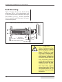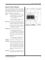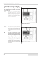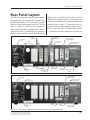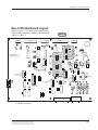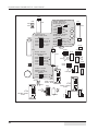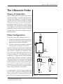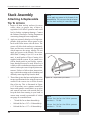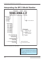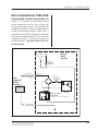
1
04 04 04 04 05 05 05 05 06 06 06 06 07 07 07 07 08 08 08 08 09 09 09 09 10 10 10 10 11 11 11 11 12 12 12 12 13 13 13 13 14 14 14 14 15 15 15 15 16 16 16 16 17 17 17 17 18 18 18 18 19 19 19 19 20 20 20 20 21 21 21 21 22 22 22 22 23 23 23 23 24 24 24 24 25 25 25 25 User’s Manual Dukane Part No. 403 - 558 - 03 Dukane Corporation • Ultrasonics Division • 2900 Dukane Drive • St. Charles, Illinois 60174 USA • TEL (630) 797 - 4900 • FAX (630) 797 - 4949 ISO 9001:2000 Dukane products are manufactured in ISO registered facilities www.dukane.com/us Dynamic Process Controller DPC™ II – User’s Manual Copyright © 2002—2005 Dukane Corporation Ultrasonics Division 2900 Dukane Drive St. Charles, IL 60174 USA Notice of Rights: All rights reserved. No part of this manual including the interior design, cover design and icons may be reproduced, transmitted or utilized in any form or by any means, electronic, mechanical, photocopying, recording, or by any information storage and retrieval system, without written permission from Dukane Corporation. Notice of Liability: The information contained is this manual is distributed on an “As is” basis, without warranty. While every precaution has been taken in the preparation of this manual, Dukane Corporation shall not have any liability to any person or entity with respect to any liability, loss, or damaged caused or alleged to be caused directly or indirectly by the instructions contained in this manual, or by the hardware and software products described herein. Printed in the United States of America. Dukane Part Number: 403–558–03 Dukane ultrasonic equipment is manufactured under one or more of the following U.S. Patents: 3,780,926 3,825,481 4,131,505 4,277,710 5,798,599 and 5,880,580. DPC™ is a trademark of Dukane Corporation ii Dukane Manual Part No. 403–558–03 Section 1 – Introduction DPC–2 Manual Revision History Revision Number Revision History Date –00 Original Release 2001–Mar–20 –01 Update Rev–1 Motherboard Changes 2002–Dec–14 –02 Update AC Power Reqm’ts in Table 11—I Add Figure 5–13 Press Board Cycle Activation Jumper Block on p. 50 Elaborate NOTE for setting Manual Amplitude on p. 46 Update TOC, Appendix A and Index 2005–Apr–22 –03 Removed “(Do not clamp)’ on Figure 5-16 on page 65. 2005-Nov-29 Updated website name, and Regulatory Compliance Info. 2010-May-17 Dukane Corporation • Dukane Manual Part No. 403–558–03 • Ultrasonics Division iii Dynamic Process Controller DPC™ II – User’s Manual This page intentionally left blank iv Dukane Manual Part No. 403–558–03 Section 1 – Introduction Table of Contents Section 1 – Introduction............................................................ 1 Before Operating....................................................................................... 3 Read The Manual First..................................................................................... 3 Caution and Warnings..................................................................................... 3 Drawings Labels................................................................................................ 3 Manual Organization................................................................................. 4 DPC–II Overview......................................................................................... 6 Key DPC–II Features.................................................................................... 7 Section 2 – Safety Tips............................................................... 9 Health & Safety Tips................................................................................. 11 Plastics Health Notice..................................................................................... 12 Electrical Grounding Safety........................................................................... 12 RFI Considerations.................................................................................... 13 Section 3 – Unpacking & Installation..................................... 15 Shipping Carton Contents....................................................................... 17 DPC Placement......................................................................................... 17 Benchtop......................................................................................................... 17 Rack Mounting............................................................................................... 18 Rear Panel Overview................................................................................ 19 Ground the System................................................................................... 19 Connect the Cables.................................................................................. 20 Hand Probe System........................................................................................ 20 Automated Probe System.............................................................................. 20 Multiple Probe System................................................................................... 22 Automated Thruster System.......................................................................... 23 Dukane Press System...................................................................................... 24 Rear Electrical Power Switch.......................................................................... 25 Section 4 – Controls & Displays............................................... 27 Front Panel Layout................................................................................... 29 AC Power.................................................................................................. 30 Generator Status Section......................................................................... 30 Status Control Keys........................................................................................ 30 System Status Display..................................................................................... 31 System Power Output Display....................................................................... 32 Dukane Manual Part No. 403–558–03 Dynamic Process Controller DPC™ II – User’s Manual Section 5 – Rear Connectors................................................... 33 Rear Panel Layout (Rev–0 and Rev–1)..................................................... 35 Identifying Rev–0 & Rev‑1 Motherboards............................................... 36 System Input Connector (Rev–1)............................................................. 37 System Input Connector (Rev–0)............................................................. 39 System Output Connector....................................................................... 41 Remote Amplitude Control..................................................................... 45 Manual Amplitude Control..................................................................... 46 Power Signal Output Module.................................................................. 47 Press Control Module............................................................................... 48 Multi–Point Module................................................................................. 51 Jumper Block Options.............................................................................. 52 Rev–1 Motherboard Layout..................................................................... 53 Rev–0 Motherboard Layout..................................................................... 55 Section 6 – Probes/Probe Stacks............................................. 57 The Ultrasonic Probe................................................................................ 59 Theory of Operation...................................................................................... 59 Probe Configuration...................................................................................... 59 Ultrasonic Horn............................................................................................... 60 Booster............................................................................................................ 60 Probe Selection............................................................................................... 61 20kHz & 40kHz DPC II Compatiable Probes.................................................. 62 Stack Assembly......................................................................................... 70 Installing Replaceable Tips............................................................................. 70 Mounting Stud to Horn/Booster.................................................................... 71 Horn to Booster.............................................................................................. 72 Booster to Probe............................................................................................. 72 Horn to Probe................................................................................................. 72 Torque Unit Conversion Chart................................................................. 73 Stack Disassembly..................................................................................... 74 Booster Notes........................................................................................... 77 Stack Mounting........................................................................................ 78 Section 7 – DPC Checkout....................................................... 79 Startup and Self–Test............................................................................... 81 System Test............................................................................................... 82 System Operation..................................................................................... 83 vi Dukane Manual Part No. 403–558–03 Section 1 – Introduction Stopping the Weld Cycle......................................................................... 83 Hand Probe System........................................................................................ 83 Automated System......................................................................................... 83 Press System.................................................................................................... 83 End of Day...................................................................................................... 83 Section 8 – Troubleshooting................................................... 85 No Ultrasonic Output............................................................................... 87 Probe............................................................................................................... 87 Cable............................................................................................................... 87 Generator........................................................................................................ 88 Operate Input................................................................................................. 88 Generator Faults....................................................................................... 89 OVERLOAD Indicator...................................................................................... 89 OVERTEMP Indicator...................................................................................... 89 FAULT Indicator.............................................................................................. 89 Generator Errors....................................................................................... 90 INPUT TEST Indicator...................................................................................... 90 TEST Control Key............................................................................................ 90 Troubleshooting Flowchart..................................................................... 91 Section 9 – Care & Maintenance............................................ 93 Front Panel............................................................................................... 95 Rear Panel................................................................................................. 95 Chasis........................................................................................................ 95 Stack Surfaces........................................................................................... 96 Stack Maintenance......................................................................................... 96 Stack Inspection.............................................................................................. 96 Even Contact................................................................................................... 96 Uneven Contact.............................................................................................. 96 Crowning........................................................................................................ 97 Center Depression.......................................................................................... 97 Corrosion......................................................................................................... 97 Probe Reconditioning.............................................................................. 98 Overview......................................................................................................... 98 Machining the Mating Surfaces.................................................................... 98 Manual Resurfacing....................................................................................... 98 Dukane Manual Part No. 403–558–03 vii Dynamic Process Controller DPC™ II – User’s Manual Section 10 – Contacting Dukane.......................................... 101 Ultrasonics Division Main Office........................................................... 103 Email Addresses...................................................................................... 104 Telephone Extensions............................................................................ 104 Section 11 – Specifications.................................................... 105 Regulatory Compliance.......................................................................... 107 Federal Communications Commission........................................................ 107 CE Marking (Conformité Europeéne).......................................................... 107 Dimensions............................................................................................. 108 Operating Enviornment......................................................................... 108 Power Requirements.............................................................................. 109 Interpreting The DPC Model Number................................................... 110 Section 12 – Warranty........................................................... 111 Domestic warranty................................................................................. 113 International Warranty.......................................................................... 114 Tooling Warranty................................................................................... 114 Appendix A - List of Figures................................................. 115 Appendix B - List of Tables................................................... 117 Appendix C - User Supplied Circuitry................................... 119 Manual Switch Circuit............................................................................ 120 Automation Switch Circuits................................................................... 121 Non–Isolated Automation Controls...................................................... 122 Current Sink.................................................................................................. 123 Current Source.............................................................................................. 125 Isolated Automation Current Source.................................................... 127 Index...................................................................................... 129 viii Dukane Manual Part No. 403–558–03 Section 1 – Introduction This page intentionally left blank Dukane Manual Part No. 403–558–03 ix Dynamic Process Controller DPC™ II – User’s Manual This page intentionally left blank Dukane Manual Part No. 403–558–03 Section 1 – Introduction Section 1 Introduction • General Information • Manual Organization • DPC–II Overview • Key DPC–II Features Before Operating..............................................3 Read The Manual First.............................................3 Caution and Warnings.............................................3 Drawings Labels......................................................3 Manual Organization........................................4 DPC–II Overview...............................................6 Key DPC–II Features..........................................7 Dukane Corporation • Dukane Manual Part No. 403–558–03 • Ultrasonics Division Dynamic Process Controller DPC™ II – User’s Manual This page intentionally left blank Dukane Manual Part No. 403–558–03 Section 1 – Introduction Important User Information Read This Manual First Before operating the DPC™ II, read this User’s Manual to become familiar with the system. This will ensure correct and safe operation. The manual is organized to allow you to learn how to safely operate an ultrasonic system. The examples given are chosen for their simplicity to illustrate basic setup procedures. Notes and Tips Throughout this manual we use NOTES to provide information that is important for the successful application and understanding of the product. A NOTE block is shown to the right. NOTE NOTE statements provide additional information or highlight procedures. Cautions and Warnings In addition, we use special notices to make you aware of safety considerations. These are the CAUTION and WARNING blocks as shown here. They represent increasing levels of important information. These statements help you to identify and avoid hazards and recognize the consequences. One of three different symbols also accompany the CAUTION and WARNING blocks to indicate whether the notice pertains to a condition or practice, an electrical safety issue or a hand protection issue. CAUTION CAUTION statements identify conditions or practices that could result in damage to the equipment or other property. WARNING WARNING statements point out conditions or practices that could result in personal injury or loss of life. Drawings and Tables The figures and tables are identified by the section number followed by a sequence number. The sequence number begins with one in each section. The figures and tables are numbered separately. The figures use arabic sequence numbers (e.g. –1, –2, –3) while the tables use roman sequence numerals (e.g. –I, –II, –III). As an example, Figure 3–2 would be the second illustration in section three while Table 3—II would be the second table in section three. Dukane Manual Part No. 403–558–03 Condition or Practice Electrical Hazard Hand Hazard Dynamic Process Controller DPC™ II – User’s Manual Manual Organization Section 1 – Introduction describes the manual organization and the key features of the Dukane DPCTM (Dynamic Process Controller) II Generator. Section 2 – Safety discusses health, safety, grounding and RFI considerations. Section 3 – Unpacking and Installation explains the DPC II placement and setup. It also shows the cable connections for quick–start operation. Section 4 – Controls & Displays describes the function of the front panel control keys and status display. Section 5 – Connectors gives the function, pinout and signal description of the rear panel connectors on the DPC II . Operation of the optional modules is described in detail. The difference in the motherboard revisions is identified along with internal jumper blocks to control process automation. Section 6 – Hand Probe and Stack Assembly describes the assembly and mounting of both hand probes and probe stack assemblies. Section 7 – System Checkout describes basic system tests to ensure that the DPC II is functioning properly. Section 8 – Troubleshooting provides helpful tips on solving the most common problems. Section 9 – Maintenance lists a schedule of suggested preventive maintenance items. Section 10 –Contacting Dukane provides information on contacting or obtaining support from your Dukane Ultrasonics team. Section 11 –Specifications lists the DPC II dimensions, power and space requirements. It also interprets the model number coding. Section 12 –Warranty contains a copy of our equipment warranty and tooling warranty. Dukane Manual Part No. 403–558–03 Section 1 – Introduction Appendices A – List of Figures. B – List of Tables. C – Sample Circuitry for user supplied automation. Dukane Manual Part No. 403–558–03 Dynamic Process Controller DPC™ II – User’s Manual DPC II Overview The DPC™ II is the lowest–cost expandable probe system in Dukane’s Dynamic Process Controller product family. This system is designed for use with ultrasonic applications that require use of automated thruster systems or hand probes. The DPC II generator provides basic system control inputs and system monitor and status outputs. This makes the DPC II ideal for automated control systems applications. Signal conditioning and electrical isolation are also provided. The DPC II includes the same internal ultrasonic generator circuitry and reliability as the other members of the DPC generator family. Optional modules are available to enhance the DPC’s ability to meet a variety of process requirements. The most common options include Amplitude control modules, a Power Signal Output module and up to two Multi–Probe controller boards for multiple probe systems. In most cases, DPC II systems in the field can be upgraded on-site Like the other DPC models, all DPC II units (except the highest power models) feature a universal power supply with dual line–voltage input . In addition, the generator is designed and tested to comply with the FCC and CE regulations that apply to this product. See Table 11—I Dukane Manual Part No. 403–558–03 Section 1 – Introduction DPC II Key Features • Dual Line–Voltage Universal Power Supply means that the DPC II will operate worldwide. Auto-Ranging means that adjustments by the operator related to power input are unnecessary. • Line Voltage Regulation automatically maintains a constant output regardless of line voltage deviation. See Table 11—I Within specified ranges • Load Regulation provides constant amplitude automatically up to the rated overload power level. • Pulse Width Modulation is Dukane’s patented circuitry that allows the DPC power supply to efficiently control the voltage sent to the transducer in the acoustic stack. • Linear Ramp Softstart circuitry is provided allowing the acoustic stack to be brought to operating amplitude smoothly, minimizing the startup shock stress. • Auto-Trac Tuning automatically tracks the resonant frequency of the acoustic stack (horn, booster, transducer), and adjusts the generator output frequency to match it. • System Connections are provided for automation equipment to monitor and control the ultrasonic welding process. • Modular Design simplifies upgrades and increases flexibility as your application requirements change. • Flow Through Cooling Tunnel with a matched high–performance heatsink and thermostatically controlled fan reduces thermal gradients and increases component life. • Electronic Overload protection prevent component failure. (continued on next page) Dukane Manual Part No. 403–558–03 Dynamic Process Controller DPC™ II – User’s Manual • Multi–Point Control Module option permits one DPC to handle up to eight probes in an automation environment (DPC II or DPC II Plus). • Press Board option provides control for a Dukane ultrasonic press and thruster. • CE Certification means that the DPC II meets the required European standards to be sold and used in Europe. • ISO 9001 Certification means that the DPC II is manufactured to very high quality standards and assures you of Dukane’s commitment to being a quality vendor and its goal of continuous improvement. Dukane Manual Part No. 403–558–03 Section 2 – Safety Tips Section 2 Safety Tips • Health & Safety • RFI Considerations Health & Safety Tips........................................11 Plastics Health Notice.............................................12 Electrical Grounding Safety....................................12 RFI Considerations..........................................13 Dukane Corporation • Dukane Manual Part No. 403–558–03 • Ultrasonics Division Dynamic Process Controller DPC™ II – User’s Manual This page intentionally left blank 10 Dukane Manual Part No. 403–558–03 Section 2 – Safety Tips Health and Safety Tips Please observe these health and safety recommendations for safe, efficient, and injury-free operation of your equipment. In this manual, the term system refers to a complete group of components associated with the welding of plastic or metal parts, also known as an ultrasonic assembly system. A typical system consists of a generator and/or ultrasonic process controller, start and stop switches, power controls, connecting cables, and the probe assembly which includes the transducer, booster, horn and replaceable horn tip. Proper Installation – Operate system components only after they are properly installed and checked. No Unauthorized Modifications – Do not modify your system in any way unless authorized to do so by Dukane Corporation. Unauthorized modifications may cause injury to the operator and/or equipment damage. In addition, unauthorized modifications will void the equipment warranty. Keep the Cover On – Do not remove the equipment cover during operation. The generator produces hazardous electrical voltages which could cause injury. Grounded Electrical Power – Operate this equipment only with a properly grounded electrical connection. (See Electrical Safety Grounding Instructions on the next page). Comply with Regulations – You may be required to add accessories to bring the system into compliance with applicable OSHA regulations. Dukane Manual Part No. 403–558–03 IMPORTANT Never operate the DPC II with the cover off. This is an unsafe practice and may cause injury. CAUTION Parts being joined ultrasonically sometimes vibrate at audible frequencies. Wear ear protection to reduce annoying or uncomfortable sounds. In addition, sound absorbing materials, enclosures or sound deflectors may be installed to reduce the noise level. 11 Dynamic Process Controller DPC™ II – User’s Manual Plastics Health Notice Before using any Dukane ultrasonic welding system, be sure you are familiar with OSHA regulations from the U.S. Department of Labor about the particular type of plastic(s) you are using. When plastic materials are being processed, they may emit fumes and/or gases that could be hazardous. Make sure there is proper ventilation whenever these plastics are processed. Electrical Safety Grounding Instructions For safety, the power cords used on all Dukane products have a three-prong, grounding-type Approved 2 pole, 3 wire grounding receptacle BRYANT No. 5621 or equivalent to NEMA 5–15R or 5–20R Figure 2-1 Example of 120 Volt, Grounded, 3-Prong Receptacle Approved 2 pole, 3 wire grounding receptacle HUBBELL No. 5652 or equivalent to NEMA 6–15R or 6–20R Figure 2-2 12 Example of 220 Volt, Grounded, 3-Prong Receptacle CAUTION If you must have a twoprong electrical receptacle, we strongly recommend that you replace it with a properly grounded three-prong type. Have a qualified electrician replace it following the National Electric Code and any local codes and ordinances that apply. See Figures 2-1 and 2-2. CAUTION If there is any question about the grounding of your receptacle, have it checked by a qualified electrician. Do not cut off the power cord grounding prong, or alter the plug in any way. If an extension cord is needed, use a three-wire cord that is in good condition. The cord should have an adequate power rating to do the job safely. It must be plugged into a grounded receptacle. Do not use a two-wire extension cord with this product. Dukane Manual Part No. 403–558–03 Section 2 – Safety Tips The power cable normally provided for international use is compatible with many power outlets (refer to Figure 2-3.) However, if your application requires another type of cable, check with the local Dukane products representative, and follow local regulations concerning proper wiring and grounding. Grounding Contacts Typical Outlet AC Power Cable (Provided) RFI Considerations In addition to the safety considerations, proper grounding at the generator power cord is essential for the effective suppression of RFI (Radio Frequency Interference). Every DPC contains a RFI filter which blocks noise on the AC power line from entering the DPC control circuitry. This filter also prevents ultrasonic RFI from being fed back into the AC power line. In order for the RFI filter to operate properly, it is necessary to adequately ground the DPC. Run an additional grounding wire from the rear grounding connection (see Figure 2-4) to the nearest grounded metal pipe or equivalent earth ground by means of a ground clamp. Use at least an 14 AWG wire for the connection to the DPC chassis. Stranded is more flexible and easier to work with than solid wire. However if you use stranded wire, crimp spade lugs on the end to ensure a good connection. If you have a color choice, green is the commonly accepted color for an electrical ground connection. Figure 2-3 International 220/240V Grounding 10 – 24 x 1/2" threaded stud I O 14 AWG to Earth Ground Figure 2-4 DPC Grounding Arrangement 14 AWG wire has a diameter of 1.63mm or Dukane Manual Part No. 403–558–03 13 Dynamic Process Controller DPC™ II – User’s Manual This page intentionally left blank 14 Dukane Manual Part No. 403–558–03 Section 3 – Unpacking and Installation Section 3 Unpacking & Installation • Unpacking the DPC • Placement of the DPC • Rear Panel Overview • Grounding the System • Connecting the Cables Shipping Carton Contents...............................17 DPC Placement...............................................17 Benchtop...............................................................17 Rack Mounting......................................................18 Rear Panel Overview.......................................19 Ground the System.........................................19 Connect the Cables........................................20 Dukane Corporation • Dukane Manual Part No. 403–558–03 Hand Probe System...............................................20 Automated Probe System......................................20 Multiple Probe System...........................................22 Automated Thruster System..................................23 Dukane Press System.............................................24 Rear Electrical Power Switch..................................25 • Ultrasonics Division 15 Dynamic Process Controller DPC™ II – User’s Manual This page intentionally left blank 16 Dukane Manual Part No. 403–558–03 Section 3 – Unpacking and Installation Shipping Contents Quantity Item Part Number 1 DPC II ** 1 DPC II User's Manual 403–558–xx ** DPC Part Number depends upon Frequency and Power Rating AC power cord and cables as specified. See your Packing List. Compare with Table 3-II on page 21. Table 3—I DPC II Shipping Container Contents Carefully open the shipping container, and make sure it contains the items shown in Table 3–I. Inspect the DPC for damage. Report any damage immediately to Dukane Ultrasonics Support/Service. DPC Placement Placement of the DPC depends on whether it is a benchtop or rack-mounted configuration Benchtop Place the DPC on a flat surface with its front panel easily accessible. Make certain the placement and cabling do not interfere with the assembly operation. Allow 4 inches (10 cm) at the rear of the DPC for cable clearance. Allow 2 inches (5 cm) of space on either side of the DPC for air circulation. Refer to the illustration in Figure 3-1. CAUTION Allow space for air ventilation around the DPC II chassis, the air intake and exhaust. The fan draws in fresh air to cool the internal components, reduce thermal gradients and increase component life. When viewed from the front, the fresh air intake is on the right and the hot air exhaust is on the left side. If excessive dust accumulates in the slots, wipe or vacuum them clean. Do not use compressed air as this may force the dust inside the chassis. Allow 4 inches (10 cm) space for cables behind the DPC Intake Vent for Thermostatically Controlled Fan SYSTEM POWER OUTPUT 0 40 20 PERCENTAGE 60 80 Cooling Air 100 OF AVAILABLE POWER FAULT INPUT TEST OVERLOAD ON LINE OVERTEMP OFF LINE 2200 STATUS Exhaust Air from Flow–Thru Cooling Tunnel Figure 3-1 ON LINE Dynamic Process Controller TEST OFF LINE DPC II tilation, Allow space for ven each side. 2 inches (5 cm) on DPC Benchtop Installation Dukane Manual Part No. 403–558–03 17 Dynamic Process Controller DPC™ II – User’s Manual Rack Mounting Figure 3-2 shows the use of a bracket kit in mounting a DPC to a 19-inch equipment rack. (Contact Ultrasonic Sales at Dukane, and request Part Number US-1155.) The DPC illustrated has the standard, angled front panel of impactresistant ABS plastic. Allow 4 inches (10 cm) of space behind the DPC for cables SYSTEM POWER OUTPUT 0 20 2200 40 60 80 100 PERCENTAGE OF AVAILABLE FAULT ON LINE POWER INPUT TEST OVERLOAD OVERTEMP OFF LINE STATUS Dynamic Process Controlle r DPC II ON LINE TEST OFF LINE Approximate 17.35 inches (44 cm ) 19 inches (48 cm) imate Approx in 5 .2 22 ) (57 cm Figure 3-2 DPC Rack Mount Installation Using Bracket Kit 18 CAUTION Allow 2 inches on either side of the DPC II chassis for air ventilation. The fan draws in fresh air to cool the internal components, reduce thermal gradients and increase component life. When viewed from the front, the fresh air intake is on the right and the hot air exhaust is on the left side. If excessive dust accumulates in the slots, wipe or vacuum them clean. Do not use compressed air as this may force the dust inside the chassis. Dukane Manual Part No. 403–558–03 Section 3 – Unpacking and Installation Rear Panel Overview Familiarize yourself with the connection points for power, ground, ultrasound output, system I/O and the optional modules on the rear of the DPC II shown below in Figure 3–3. The standard connectors are labeled with the black boxes. The optional modules are labeled with italics. The grounding lug, serial number tag, rear AC power switch and AC power input are located in the same position on all DPC II, DPC II Plus, DPC III and DPC IV generators. NOTE Not all of the optional modules illustrated below can be installed simultaneously. They are shown to represent the various configurations that can be assembled to meet specific requirements. See Section 5 for more detailed information on the modules, their functions and capabilities. Slave Multi–Probe Controller Module Grounding Lug Rear AC Power Switch IEC AC Power Input Model No. Tag Master Multi–Probe Controller Module Press Control Module System Output Connector System Input Connector Power Signal Output Module Manual Amplitude Control Module J1 Ultrasound Output (BNC) Serial No. Tag Figure 3-3 Rev–1 DPC II Rear Panel and Optional Modules Ground the System The DPC II includes an internal RFI filter. The standard building AC ground connection is normally not sufficient to completely suppress the RFI. Attach a ground cable from the DPC grounding lug (located next to the rear AC power switch) to an earth ground. If you are using a press or automated probe system, each piece of equipment must also be solidly grounded. Refer to Figures 3–4 through 3–8 for the proper ground Dukane Manual Part No. 403–558–03 CAUTION Before attaching the cables, make sure that the DPC II is properly grounded. Refer to the appropriate cabling diagram (Figures 3–4 thru 3–8) for the correct grounding connections. 19 Dynamic Process Controller DPC™ II – User’s Manual Connect the Cables The instructions here and the diagrams in Figures 3–4 through 3–7 are meant to serve as a quick start guide. The connectors and their pinouts are discussed in greater detail in Section 5. Manual Probe System Step 1. Ground the DPC II chassis. Step 2. Attach the System In adapter cable (see Figure 3–4) to the 14-pin AMP connector at the end of the probe cable. Step 3. Connect the other end of the adapter to the System In HD-15 connector on the rear of the DPC II. Step 4. Attach the high voltage ultrasound coaxial cable to the rear-panel J1 connector. Step 5. Optional – If your system has a Press Control Module, you will also need a jumper block (Part No. 2001293) to replace the normally closed contact from the Emergency Stop safety switch. Step 6. Attach the power cord to the DPC II and plug the other end into an approved AC outlet. Automated Probe System Step 1. Ground the DPC II chassis and the probe support. Step 2. Attach the high voltage coax cable from the probe mount to the rear-panel DPC connector J1 (see Figure 3–5). Step 3. Connect the automation control cable from the user–supplied automation equipment to the System Input rear panel HD-15 connector (Figure 3–5). 20 CAUTION Make sure electrical power is OFF before connecting/disconnecting cables or installing/removing modules from the DPC II. Make sure BOTH the front and rear panel AC power breaker switches are in the OFF position. Failure to turn off the power may result in damage to the DPC and/or the modules. CAUTION The power cord is equipped with a threeprong, grounded-type plug for your safety. Whenever a two-slot receptacle is encountered, we strongly recommend that it be replaced with a properly grounded three-lead receptacle. Have a qualified electrician perform the installation in accordance with the National Electrical Code and local codes and ordinances. DO NOT cut off the AC power cord grounding prong or alter the plug in any way. Dukane Manual Part No. 403–558–03 Section 3 – Unpacking and Installation Jumper Block Part No. 200–1293 Grounding Lug � – WARNING– Power Signal Output Module ULTRASOUND AMPLITUDE Power Signal Output 60% 80% 40% MIN. 100% MAX. Zero Adjust Power Monitor Jacks J901 TO THRUSTER POWER LINE MUST BE GROUNDED AT OUTLET LINE VOLTAGE 200–240Vac 50/60Hz 15A MONITOR JACKS + US 10000 – WARNING! – REMOVE ALL POWER BEFORE REMOVING COVER OR CONNECTING OR DISCONNECTING CABLES. J1 100% AMP = 10.0VDC � SYSTEM IN � ULTRASOUND OUTPUT � 14–Pin AMP to HD–15 Adapter Part No. 200–1248 � Flexible + Coaxial Cable 20kHz Part No. 200–624 40kHz Part No. 200–759 (Included with probe) 110 VAC or 220 VAC Earth Ground Pins 3 & 9 Connected DUKANE CORP ST. CHARLES, IL 60174 MADE IN USA MODEL NUMBER 200-240 VAC, 50-60Hz, 15A #14 Gauge Wire 5 9 POWERLINE MUST BE GROUNDED AT OUTLET – SYSTEM OUT 3 6 SERIAL NUMBER J902 BASE/ ABORT � 1 U.S.PAT ENT 4,277,710 Figure 3-4 DPC II Hand Probe Cable Connections Step 4. Optional – Attach the status output cable from the user–supplied automation equipment to the System Output DB-25 connector. Not all automation systems will have this cable. Step 5. Attach the power cord to the DPC II and plug the other end into an approved AC outlet. Grounding Lug � The 3–prong AC Line cords supplied are matched to the DPC II power rating and the continent of specified use. The part numbers are — 200–1109 North America 110V 200–1110 North America 220V 200–1111 Continental Europe Table 3—II DPC II AC Power Cord Part Numbers U.S.PAT ENT 4,277,710 SERIAL NUMBER Power Signal Output Module ULTRASOUND AMPLITUDE Power Signal Output 60% 80% 40% MIN. 100% MAX. Zero Adjust – WARNING– Power Monitor Jacks POWER LINE MUST BE GROUNDED AT OUTLET MONITOR JACKS + LINE VOLTAGE 200–240Vac 50/60Hz 15A US 10000 – WARNING! – REMOVE ALL POWER BEFORE REMOVING COVER OR CONNECTING OR DISCONNECTING CABLES. J1 100% AMP = 10.0VDC SYSTEM OUT SYSTEM IN MODEL NUMBER 200-240 VAC, 50-60Hz, 15A #14 Gauge Wire � � Ultrasound Input POWERLINE MUST BE GROUNDED AT OUTLET – P/N 200–479 DUKANE CORP ST. CHARLES, IL 60174 MADE IN USA � � � Grounding Lug ULTRASOUND OUTPUT Coaxial Cable � RG62B/U Automation Control P/N 200–1203 110 VAC or 220 VAC #14 Gauge Wire Automation Equipment Status Output P/N 200–1302 Earth Ground Figure 3-5 DPC II Automated Probe Cable Connections Dukane Manual Part No. 403–558–03 21 Dynamic Process Controller DPC™ II – User’s Manual Multiple Probe System Step 1. Ground the DPC II chassis and the probe support. Step 2. Attach the short coaxial cable from the rear-panel DPC generator U/S output J1 (see Figure 3–6) to the MPC U/S input (supplied with the Master MPC). Step 3. Attach another high voltage coax cable from the rear MPC channel 1 probe output to the first probe. Attach a separate cable from each output channel to each probe. Step 4. CAUTION To e n s u r e s a f e a n d trouble–free operation, ground the DPC chassis and probe mount as shown in Figures 3–4 to 3–7. Use a STAR configuration (illustrated below). Do not DAISY CHAIN the grounds. DPC Chassis Grounding Lug #14 Gauge Stranded or Solid Wire Connect the automation control cable from the user–supplied automation equipment to the System Input rear panel HD-15 connector. Step 5. NOTE The automated system cabling schematics in Figures 3–5, 3–6 and 3–7 are intended to represent connections for a typical automation system. Your system cabling may vary slightly from the Attach the power cord to the DPC II and plug the other end into an approved AC outlet. Grounding Lug #14 Gauge Stranded or Solid Wire Earth Ground Attach the status output cable from the user–supplied automation equipment to the System Output DB-25 connector. Step 6. Thruster or Probe Mount Grounding Lug P/N 200–479 U. S . PAT E N T 4 , 2 7 7 , 7 1 0 SERIAL NUMBER 5 – WARNING– POWER LINE MUST BE GROUNDED AT OUTLET LINE VOLTAGE 200–240Vac 50/60Hz 15A 6 2 7 3 8 4 MODEL NUMBER 2 0 0 - 2 4 0 VAC, 5 0 - 6 0 H z , 1 5 A #14 Gauge Wire 1 MPC Master Module RG62B/U Input Coax P/N 200–479–01 Power Signal Output Module ULTRASOUND AMPLITUDE Power Signal Output 60% 80% 40% MIN. 100% MAX. Zero Adjust Power Monitor Jacks MONITOR JACKS + Ultrasound Input(s) US 10000 DUKANE CORP ST. CHARLES, IL 60174 MADE IN USA – WARNING! – POWERLINE MUST BE GROUNDED AT OUTLET REMOVE ALL POWER BEFORE REMOVING COVER OR CONNECTING OR DISCONNECTING CABLES. – J1 100% AMP = 10.0VDC SYSTEM OUT SYSTEM IN ULTRASOUND OUTPUT Grounding Lug Coaxial Cable(s) RG62B/U Automation Control P/N 200–1203 110 VAC or 220 VAC Automation Equipment Status Output P/N 200–1302 #14 Gauge Wire Earth Ground Figure 3-6 DPC II Multiple Probe Conntroller Cable Connections 22 Dukane Manual Part No. 403–558–03 Section 3 – Unpacking and Installation Automated Thruster System Step 1. Ground the DPC II and the Thruster as shown in Figure 3–7. Step 2. Attach the high voltage RG62B/U coax cable from the rear-panel DPC II connector J1 to the ultrasound input J1 on the thruster (see Figure 3–7). Step 3. Connect the Automation Control cable from the user–supplied automation equipment to the System Input rear panel HD-15 connector. Step 4. Attach the Status Output cable from the user–supplied automation equipment to the Status Output DB-25 connector. Step 5. Connect the Press Base Input cable from J35 on the Press Base to the DB-9 connector (J902) on the Press Control Module. If the automation system does not have a connection to J902, you may need a jumper block (Part No. 200-1293) to replace the normally closed contact from the press base Emergency Stop safety switch. Step 6. Connect the Operational Control cable from the user–supplied automation equipment to the 36–contact Thruster control connector (J901) on the Press Control Module. Step 7. Attach the power cord to the DPC II and plug the other end into an approved AC outlet. 80–100 psi SERIAL NUMBER – WARNING– Power Signal Output Module ULTRASOUND AMPLITUDE Power Signal Output 60% 80% 40% MIN. 100% MAX. Zero Adjust Power Monitor Jacks J901 TO THRUSTER POWER LINE MUST BE GROUNDED AT OUTLET LINE VOLTAGE 200–240Vac 50/60Hz 15A MONITOR JACKS + – WARNING! – POWERLINE MUST BE GROUNDED AT OUTLET REMOVE ALL POWER BEFORE REMOVING COVER OR CONNECTING OR DISCONNECTING CABLES. J1 100% AMP = 10.0VDC SYSTEM IN MODEL NUMBER 200-240 VAC, 50-60Hz, 15A #14 Gauge Wire � � � J40 J3 US 10000 DUKANE CORP ST. CHARLES, IL 60174 MADE IN USA – SYSTEM OUT (Optional) � Ultrasound Input J1 P/N 200–479 � U.S. PAT ENT 4,277,710 J902 BASE/ ABORT Grounding Lug Top–Of–Stroke Part No. 200–1104 � Air Supply P/N 438–528 J901 Operational Control ULTRASOUND OUTPUT � Grounding Lug � � Coaxial Cable Automation RG62B/U Control Cable P/N 200–1203 Status Output Cable P/N 200–1302 Base Cable Automation Equipment Part No. 200–1124 110 VAC or 220 VAC — or — Jumper Block Part No. 200–1293 to J902 1 3 6 5 9 Pins 3 & 9 Connected #14 Gauge Wire Earth Ground Figure 3-7 DPC II Automated Thruster Cable Connections Dukane Manual Part No. 403–558–03 23 Dynamic Process Controller DPC™ II – User’s Manual Dukane Press System Step 1. Step 2. Step 3. Step 4. Step 5. CAUTION Ground the DPC II, the Thruster and the Base as shown in Figure 3–8. Attach the high voltage coax cable from the press J1 connector to the DPC Ultrasound Out connector (J1). Connect the Press Base Input cable from J35 on the Press Base to the DB-9 connector (J902) on the Press Control Module. Connect the Operational Control cable from J3 at the top of the press to the 36–contact Thruster control connector (J901) on the Press Control Module. Attach the power cord to the DPC II and plug the other end into an approved AC outlet. Use the STAR configuration illustrated below and in Figure 3–8 to ground the DPC chassis, base and thruster. Do not DAISY CHAIN the grounds. DPC Chassis Grounding Lug Thruster Grounding Lug #14 Gauge Stranded or Solid Wire #14 Gauge Stranded or Solid Wire Base/Fixture Grounding Lug Earth Ground Electrical Power 80–100 psi Ultrasound Input � Air Supply � J1 J40 J3 J902 BASE/ ABORT – WARNING– ULTRASOUND AMPLITUDE Power Signal Output 60% 80% 40% MIN. 100% MAX. Zero Adjust Power Monitor Jacks POWER LINE MUST BE GROUNDED AT OUTLET J901 TO THRUSTER � SE R I A L N U M B E R Power Signal Output Module LINE VOLTAGE 200–240Vac 50/60Hz 15A MONITOR JACKS + US 10000 DUKANE CORP ST. CHARLES, IL 60174 MADE IN USA – WARNING! – POWERLINE MUST BE GROUNDED AT OUTLET REMOVE ALL POWER BEFORE REMOVING COVER OR CONNECTING OR DISCONNECTING CABLES. – SYSTEM IN MODEL NUMBER 2 0 0 - 2 4 0 VAC, 5 0 - 6 0 H z , 1 5 A #14 Gauge Wire � J901 to Thruster Grounding Lug J1 100% AMP = 10.0VDC SYSTEM OUT Part No. 200–479 U.S . PAT E N T 4 , 2 7 7 , 7 1 0 � ULTRASOUND OUTPUT � � � Coaxial Cable J902 to Base/Abort RG62B/U Operational Control Part No. 200–1104 #14 Gauge Wire 110 VAC or 220 VAC 8–conductor cable � J35 Part No. 200–1124 Earth Ground #14 Gauge Wire Grounding Lug � Figure 3-8 DPC II Dukane Press Cable Connections 24 Dukane Manual Part No. 403–558–03 Section 3 – Unpacking and Installation Switch The rear panel AC breaker switch (Figure 3–9) is wired in series with the front panel breaker switch (shown in Figure 4-2). When the rear breaker switch is off, it isolates the AC power feed in the chassis for safety considerations. Both the front panel and rear panel switches must be on to supply AC power to the DPC generator. Grounding Lug Rear AC Breaker Switch IEC AC Power Input Figure 3-9 Rear Panel AC Breaker Switch Dukane Manual Part No. 403–558–03 25 Dynamic Process Controller DPC™ II – User’s Manual This page intentionally left blank 26 Dukane Manual Part No. 403–558–03 Section 4 – Controls & Displays Section 4 Controls & Displays • Front Panel Layout • AC Power • Generator Status Front Panel Layout..........................................29 AC Power.......................................................30 Generator Status Section................................30 Dukane Corporation • Dukane Manual Part No. 403–558–03 Status Control Keys...............................................30 System Status Display............................................31 System Power Output Display................................32 • Ultrasonics Division 27 Dynamic Process Controller DPC™ II – User’s Manual This page intentionally left blank 28 Dukane Manual Part No. 403–558–03 Section 4 – Controls & Displays Front Panel Layout This section describes the DPC II front panel control keys and status displays. The DPC front panel is laid out in two sections as illustrated below in Figure 4-1. The two sections are 1. AC Power switch and indicator 2. Generator Status Panel which contains • Three Status Control keys • System Status display • System Power Output display FAULT INPUT TEST OVERLOAD ON LINE OVERTEMP OFF LINE Figure 4–1 DPC II Front Panel Layout Dukane Manual Part No. 403–558–03 29 Dynamic Process Controller DPC™ II – User’s Manual 1. AC Power Section The front-panel AC power section has a switch and power indicator that is shown in Figure 4-2. ON/OFF Green Power Indicator The AC power switch connects AC power to the generator. This breaker switch is wired in series with the rear panel power switch (Figure 3–9). It also serves as a circuit breaker that provides overload protection for the DPC. Both switches must be turned on to supply AC power to the generator. Green LED The green indicator above the switch lights when the DC bus is up, after the AC power has been switched on. At this point the generator is capable of producing an ultrasonic output signal. Front AC Power Switch Figure 4–2 Front Panel AC Power Section 2. Generator Status Panel The Generator Status Panel is subdivided into three sections which provide control and status displays. 1. Generator Control Keys 2. System Status Display 3. System Power Output Display Status Control Keys The Generator Control Key section consists of three keys as shown in Figure 4-3. ON LINE TEST OFF LINE 30 This places the generator in an operational state. It can produce an ultrasonic output signal when triggered. The TEST key momentary activates the generator to provide ultrasound output for test or setup purposes. TEST will only work in the ON LINE state. This key places the generator in a standby mode. This prevents the generator from producing an ultrasonic output signal. ON LINE Key TEST Key OFF LINE Key Figure 4–3 Generator Control Keys NOTE If a Press module is installed, these keys are only active if the Emergency Stop is not engaged. If the Emergency Stop switch is depressed, the System Status Display will not be lit and the Control Keys inactive. Dukane Manual Part No. 403–558–03 Section 4 – Controls & Displays System Status Display The System Status Display indicates one of the six system states. If that state is active, the corresponding label is lit in the display. Figure 4-4 shows the System Status Display with the ON LINE state activated. The six status conditions are described here. FAULT This indicator lights when out-of-tolerance voltage fluctuations occur that are related to one of the following conditions. 1. AC Line Voltage 2. Internal DC Power Supply (+5 VDC, +12 VDC, -12V DC or +24V DC.) INPUT TEST This indicator normally flashes red dur- ing a power-up test. If there is a problem, a steady red light appears. This means that either the input AC line voltage is out of tolerance, or an internal fault has occurred in the generator. Figure 4–4 System Status Display OVERLOAD This red indicator lights when either ON LINE of the following conditions occur. 1. An instantaneous overload caused by a mismatch between the ultrasonic signal and the resonant characteristics of the acoustic stack (transducer, booster and horn.) 2. Excessive power beyond the generator’s rated output is being drawn. The generator is capable of operation. OVERTEMP One of the power modules has over- heated and the generator has shut down. This may be caused by excessive dust in the cooling channel or a cooling fan failure. The generator will automatically reset when the module temperature drops below the trip point which is 75°C (167°F). OFF LINE The generator is in a standby mode. The ultrasound output cannot be activated. Dukane Manual Part No. 403–558–03 31 Dynamic Process Controller DPC™ II – User’s Manual System Power Output Display The tricolor System Power Output Display indicates the percentage of ultrasonic power being drawn by the load. Green GREEN Eight green vertical bars indicating 10% to 80% power output are displayed during normal operation. Figure 4-5 shows the display indicating 80% output power. Figure 4–5 Normal Operation Yellow Two yellow bars for 90% and 100% power output warn that the generator is operating near its maximum rated output. Red The last red bar indicates that the generator is in an overload condition delivering more than its rated output power. Figure 4-6 shows the red overload and two yellow warning indicators. The red warning indicator lights up just prior to an overload condition. The ultrasonic signal is shut down when an overload condition occurs. 32 RED YELLOW Figure 4–6 Warning Indicators Dukane Manual Part No. 403–558–03 Section 4 – Controls & Displays Section 5 Rear Connectors • Rear Panel Layout • System Control Inputs • System Status Outputs • Optional Modules • Internal Jumper Blocks • Motherboard Layouts Rear Panel Layout...........................................35 DPC II Motherboards.......................................36 System Input Connector (Rev–1).....................37 System Input Connector (Rev–0).....................39 System Output Connector...............................41 Remote Amplitude Control.............................45 Manual Amplitude Control Module.................46 Power Signal Output Module..........................47 Press Control Module......................................48 Multi–Point Controller Module........................51 Jumper Block Options.....................................52 Rev–1 Motherboard Layout.............................53 Rev–0 Motherboard Layout.............................55 Dukane Corporation • Dukane Manual Part No. 403–558–03 • Ultrasonics Division 33 Dynamic Process Controller DPC™ II – User’s Manual This page intentionally left blank 34 Dukane Manual Part No. 403–558–03 Section 5 – Rear Connectors Rear Panel Layout The DPC II has been built using two different motherboard designs. The original DPC II model used the DPC II board (Rev–0). The later DPC II models utilize the same motherboard as the DPC II Plus (Rev–1). Figure 5–1 shows the rear connectors and the optional modules installed into a DPC II which has the Rev–1 motherboard. No generator can have all the modules shown. Specifically the Multi–Probe Slave U/S Outputs Grounding Lug Multi–Probe Controller and the Press Control Modules are mutually exclusive. The modules are shown here to indicate their installed locations and connector types. Figure 5–2 shows the rear connectors and the optional modules installed into a DPC II which has a Rev–0 motherboard. Figure 5–3 identifies the major differences between the Multi–Probe Master U/S Outputs Press Base Abort Rear AC Power Switch IEC AC Power Input Figure 5–1 Thruster Operational Control System Output System Input Remote Amplitude Control Input Ultrasound Output DPC II (Rev–1 Motherboard) Rear Panel Connectors and Optional Modules Grounding Lug Power Signal Output Monitor Rear AC Power Switch IEC AC Power Input Figure 5–2 Multi–Probe Master U/S Input Power Signal Output Monitor Amplitude Control Output Monitor System Output System Input Ultrasound Output DPC II (Rev–0 Motherboard) Rear Panel Connectors and Optional Modules Dukane Manual Part No. 403–558–03 35 Dynamic Process Controller DPC™ II – User’s Manual DPC II Motherboards There is no operational or performance difference between the two designs of motherboards except for the pinout of the System Input connector and the optional modules the DPC II will accept. Figure 5–3 below shows the main identifying features of the Rev–0 and Rev–1 motherboards as seen with the DPC II chassis cover removed. The rear panel connectors (J701 and J702) are at the bottom of the drawing. J715 & J716 Located Here on Rev–1 Not Present on Rev–0 SH706 Here on Rev–1 Not Present on Rev–0 P707 P704 WARNING Never operate the DPC II with the cover off. The generator produces hazardous electrical voltages which could cause injury. P705 P706 P703 P705 P708 P706 P707 SH706 JU723 JU722 TIMER BD. ENABLE TIMER BD. BYPASS SWITCH DEBOUNCE FILTER TIME DELAY SELECTION BLOCK SH705 A1 B1 A1 B1 A10 B10 J716 MULTI-PROBE CONTROLLER BOARD SLAVE A10 B10 JU708 JU709 JU710 JU711 JU712 R769 J715 MULTI-PROBE CONTROLLER BOARD MASTER AMPLITUDE MONITOR OUTPUT GAIN ADJ. 1 mSEC JU719 10 mSEC JU720 22 mSEC SH704 U/S ACTIVE JU713 OVERLOAD OVERTEMP SYS. FAULT ANY FAULT JU714 JU715 JU716 NORMALLY OFF NORMALLY ON AUTO STOP FAULT AUTO END OF WELD B1 STATUS DRIVER SELECTION BLOCK SH702 J715 PRESS CONTROL BOARD A10 J710 ULTRATEST MODULE INTERFACE BOARD NO DELAY JU718 AUTOMATION SIGNALS SELECTION BLOCK STATUS RELAY SELECTION BLOCK SH703 110-3606 DUKANE CORP. JU717 110-3606 DUKANE ULTRASONICS MADE IN USA B10 J714 PRESS CONTROL BOARD JU703 JU704 JU705 U/S ACTIVE OVERLOAD OVERTEMP JU706 SYS FAULT ANY FAULT JU707 STATUS DRIVER NORMAL STATE SELECTION BLOCK SH701 1 JU701 NORMALLY OFF JU702 NORMALLY ON J712 1 REMOTE CONTROL BOARD J711 POWER SIGNAL OUTPUT BOARD 1 1 J714 DISTANCE MODULE BOARD J709 STATUS RELAY BOARD J713 ISOLATED STATUS OUTPUT BOARD J710 POWER SIGNAL OUTPUT BOARD NON-ISO SINK JU724 NON-ISO SOURCE JU725 ISOLATED JU726 SH707 J701 J702 HD15 SYSTEM INPUT DB-25 SYSTEM STATUS OUTPUT J710, J713 & J714 Located Here on Rev–0 Not Present on Rev–1 J710 Here on Rev–1 Not Present on Rev–0 SH707Here on Rev–1 Not Present on Rev–0 Figure 5–3 Identifying Characteristics of Rev–0 and Rev–1 DPC II Motherboards 36 Dukane Manual Part No. 403–558–03 Section 5 – Rear Connectors System Input Connector Rev– 1 The System Input is a HD-15 (high-density, 15 contact) female connector. Pin numbers are identified in Figure 5–4. Table 5—IA below lists the pinout and signal names of the System Input connector for a DPC II with a Rev–1 motherboard. A complete description of the input signals and their function is given on the next page. Users of custom automation will also find a list of wire color codes for the automation cable assembly (Dukane Part 200–1203) in Table 5—III. This cable is used to connect the DPC to custom automation equipment CAUTION The System Input port uses the same type of connector as a standard computer video monitor port, but it is electrically very different. DO NOT connect any video monitor devices to this connector. Doing so may result in damage to both the video device and the DPC. 5 4 3 2 1 1 2 3 4 5 6 10 6 15 14 13 12 11 Figure 5–4 HD-15F System Input Connector Pin 10 11 12 13 14 15 Figure 5–5 Cable end of SYSTEM IN connector. Signal Name Signal Description NOTE 1 +22VDC Current limited to 250 mA maximum 2 Gnd 22VDC Return (DPC Chassis Ground) 3 Iso Oper In Isolated Operate Input The connector pinout in Figure 5–4 is the female DPC panel connector. The male cable end is a mirror image and is shown in Figure 5–5. 4 Iso Common Isolated Input Common (if jumper is selected – Figure 5–9/SH707) 5 Iso Press Cntrl Isolated Press Control 6 Not Used Spare Input Pin 7 Gnd 22VDC Return (DPC Chassis Ground) 8 Sw Oper Input Switch Closure Operate Input 9 Iso Auto Stop Isolated Automation Stop Input —OR— Isolated Automation End–Of–Weld Pin Pin Pin MPC Probe 14 13 12 Selected 0 0 0 Probe 1 0 0 1 Probe 2 0 1 0 Probe 3 (set by jumper SH704 see Figure 5–15) 0 1 1 Probe 4 10 Not Used Reserved for Future Use 1 0 0 Probe 5 11 HPPI Hand Probe Press Inhibit 1 0 1 Probe 6 12 Probe I.D. Bit 0 Probe Selection Bit #0 (LSB) 1 1 0 Probe 7 13 Probe I.D. Bit 1 Probe Selection Bit #1 1 1 1 Probe 8 14 Probe I.D. Bit 2 Probe Selection Bit #2 (MSB) 15 F P Lock Front Panel Control Lock Table 5—IA Rev–1 Motherboard System Input Connector Signals Dukane Manual Part No. 403–558–03 Note: 1 = Pin Grounded (to DPC chassis) 0 = Pin Open (no connection) Probe 1 is the default selection Table 5—II Remote Probe Selection 37 Dynamic Process Controller DPC™ II – User’s Manual Input Signal Description Pin Color Signal Desc Note Pin 1 (+22V) 1 Red +22V This pin can supply +22VDC at up to 250mA to power the user’s automation controls. Red used by Belden may appear brown 2 Black Gnd Also connected to connector metal shell 3 Blue/Blk Iso Oper In 4 Green/Wht Iso Common 5 Blue/Wht Iso Auto Cntrl 6 Red/Blk Reserved 7 White/Blk Gnd 8 White Sw Oper Input 9 Orange Iso Auto Stop Pin 2 (Gnd) Pin 2 and 7 are the 22VDC and Operate returns and are tied to the chassis ground. Pin 3 (Isolated Operate In) This pin is used to initiate the operate sequence. The factory default setting is a non-isolated sink requiring a dry contact closure to ground (pins 2 or 7). This input can be changed to a source or fully isolated input by jumper block SH707. See Figures 5–14, 5–15 and Appendix C. Pin 4 (Isolated Common) This pin is used as the isolated return common if jumper block SH707 is configured as a fully isolated input (position JU726). See Figures 5–14, 5–15 and Figure C–7. Pin 5 (Isolated Press Control) This input is designed to be used in conjunction with the optional Press Control Board. The signal is used to activate the thruster up and down. The factory default setting is a non-isolated sink requiring a dry contact closure to ground (pins 2 or 7). This input can be changed to a source or fully isolated input by jumper block SH707. See Figures 5–14, 5–15 and Appendix C. Pin 6 (Not Used) Isolated input reserved for future use. Pin 7 (Gnd) Pin 2 and 7 are the 22VDC and Operate returns and are tied to the chassis ground. Pin 8 (Operate) A dry contact closure (no voltage) between pin 8 and ground (pins 2 or 7) will initiate the operate sequence and is functionally the same as pin 3. Pin 9 (Isolated Auto Stop) This signal stops the operation sequence. The factory default setting is a non-isolated sink requiring a dry contact closure to ground (pins 2 or 7). This input can be changed to a source or fully isolated input by jumper block SH707. See Figures 5–14, 5–15 38 Red used by Belden may appear brown 10 Blue Reserved 11 Orange/Blk Hand Probe Press Inhibit 12 Red/Wht Remote Probe Red used by Belden Selection (LSB) may appear brown 13 Green/Blk Remote Probe Selection 14 Black/Wht Remote Probe Selection (MSB) 15 Green F P Lock Black may be faint – Don't confuse with 9 Table 5—III System Input Automation Cable Color Code (Dukane Part No. 200–1203) and Appendix C. Pin 10 (Not Used) Isolated input reserved for future use. Pin 11 (Hand Probe Press Inhibit) The adapter cable (P/N 200–1203) has pin 11 grounded to indicate a hand probe is connected. Pins 12, 13, 14 (Probe Selection) When using the multi–probe controller module (MPC), these bits select which probe is activated. A dry contact closure between pins 12, 13 or 14 and ground (pins 2 or 7) will activate one of the probes. The pin combinations to select probes one through eight are given in Table 5—II. Pin 15 (F P Lock) A dry contact closure between pin 15 and ground (pins 2 or 7) will lock out the front panel TEST key and prevent it from being activated. This also prevents any programming changes. Dukane Manual Part No. 403–558–03 Section 5 – Rear Connectors System Input Connector Rev–0 The System Input is a HD-15 (high-density, 15 contact) female connector. Pin number are identified in Figure 5–4. Table 5—IB below lists the pinout and signal names of the System Input connector for a DPC II with a Rev–0 motherboard. A complete description of the input signals and their function is given on the next page. 5 4 3 2 1 6 10 CAUTION The System Input port uses the same type of connector as a standard computer video monitor port, but it is electrically very different. DO NOT connect any video monitor devices to this connector. Doing so may result in damage to both the video device and the DPC. 15 14 13 12 11 Figure 5–4 HD-15F System Input Connector 1 2 3 4 5 6 10 11 12 13 14 15 Figure 5–5 Cable end of SYSTEM IN connector. Pin NOTE The connector pinout in Figure 5–4 is the female DPC panel connector. The male cable end is a mirror image and is shown in Figure 5–5. Signal Name Signal Description 1 +22VDC Current limited to 250 mA maximum 2 Gnd 22VDC Return (DPC Chassis Ground) 3 Iso Oper In Isolated Operate Input 4 Iso Oper Com Isolated Operate Common 5 Iso Auto Cntrl Isolated Automation Control 6 Iso Auto Com Isolated Automation Common 7 Gnd 22VDC Return (DPC Chassis Ground) 8 Sw Oper Input Switch Closure Operate Input 9 Not Used Reserved for Future Use 10 Not Used Reserved for Future Use 11 F P Lock Front Panel Control Lock 12 Not Used (SEQ ID0) 13 Not Used (SEQ ID1) 14 Not Used (SEQ ID2) 15 Not Used (HPPI) PINOUT CHANGES The System Input pinouts shown in Tables 5—IA and 5—IB have only minor changes. They are: Isolated Automation has its own Common on Rev–0 Pin 6. This is combined with Pin 4 on the Rev–1 board. F P LOCK on Pin 11 Rev–0 is moved to Pin 15 on the Rev–1 board. HPPI on Pin 15 is not used on the Rev–0 board. It is moved to Pin 11 on the Rev–1 board. Table 5—IB Rev–0 Motherboard System Input Connector Signals Dukane Manual Part No. 403–558–03 39 Dynamic Process Controller DPC™ II – User’s Manual Input Signal Description Pin 1 (+22V) Pin 11 (F P Lock) This pin can supply +22VDC at up to 250mA to power the user’s automation controls. A dry contact closure between pin 11 and ground (pins 2 or 7) will lock out the front panel TEST key and prevent it from being activated. Pin 2 (Gnd) Pin 2 and 7 are the 22VDC, Operate and FP Lock signal returns and are tied to the chassis ground. Pins 12, 13, 14 (Remote Select) Pins 3 & 4 (Isolated Operate In) Pin 15 (Hand Probe Press Inhibit) These pins are isolated, polarity insensitive Operate Control inputs. When a signal of 5 to 24VDC is applied to one input and the other input is connected to ground, it will initiate the operate sequence. These inputs are functionally the same as pin 8. The current is internally limited to 12.5mA. Inputs reserved for future use. Inputs reserved for future use. Pins 5 & 6 (Iso. Auto Control) These pins are isolated, polarity insensitive Automation Control inputs. This input is designed to be used in conjunction with the optional Press Control Board. The signal is used to activate the thruster up and down. A signal of 5 to 24VDC is required at one pin and the other pin must be connected to ground. The current is internally limited to 12.5mA. Pin 7 (Gnd) Pin 2 and 7 are the 22VDC, Operate and FP Lock signal returns and are tied to the chassis ground. Pin 8 (Operate) A dry contact closure (no voltage) between pin 8 and ground (either pin 7 or pin 2) will initiate the operate sequence and is functionally the same as pins 3 & 4. Pin 9 (Not Used) Isolated input reserved for future use. Pin 10 (Not Used) Isolated input reserved for future use. 40 Dukane Manual Part No. 403–558–03 Section 5 – Rear Connectors System Output Connector The System Output panel connector is a DB-25 Female type. Pin numbers are shown in Figure 5–6 and pin assignments are given in Table 5—IV. There is no difference between the Rev–0 and Rev–1 motherboards. Dukane cable assembly P/N 200–1302 is used to connect the DPC to custom automation equipment to monitor the welding process. A complete description of the signals and their function is given on the following pages. Pin 13 12 11 10 9 8 7 6 5 4 3 2 1 25 24 23 22 21 20 19 18 17 16 15 14 Figure 5–6 DB-25 System Output Connector Signal Name Signal Description 1 +22VDC Current limited to 250 mA maximum 2 Gnd 22VDC Return (DPC Chassis Ground) 3 Gnd Status Driver Output Ground (DPC Chassis Ground) 4 Stat Drv Status Driver Output 5 Not Used Spare Output Pin 6 U/S Active Ultrasound Status Output (Active Low) 7 Sys Fault System Fault Output (Active Low) 8 O T Fault Overtemperature Fault Output (Active Low) 9 O L Fault Overload Fault Output (Active Low) 10 On Line On Line Status Output (Active Low) 11 Gnd Status Outputs Ground (DPC Chassis Ground) 12 Loop Fault 4–20 mA Current Loop Fault Output 1 13 Gnd Monitor Outputs Ground 14 Freq Out Frequency Monitor Output (31Vrms maximum) 15 Amp Out Amplitude Monitor Output (10.0V = 100%) 16 Pwr Sig Power Signal Monitor Output 2 17 Pwr Reg Stat Not currently available 18 MPC Ready Multi–Probe Controller Ready 3 (Active Low) 19 Iso Pwr Fail Isolated Power Fail Signal (Active Low) 20 Not Used Isolated Output (BSP) (Active Low) 21 Not Used Isolated Output (GP) (Active Low) 22 Not Used Isolated Output (RDY) (Active Low) 23 Not Used Isolated Output (ID) (Active Low) 24 Not Used Isolated Outputs Common 25 Not Used Spare Output Pin Table 5—IV CAUTION (1 amp maximum) (Active Low) (DPC Chassis Ground) (1mV = 1 watt) The System Output port uses the same type of connecor as a standard RS-232, DB25 serial interface, but it is electrically very different. DO NOT connect any RS-232 devices to this connector. Doing so may result in damage to both the serial device and to the DPC internal circuitry. (Active Low) (Isolated Gnd) System Output Connector Signals Dukane Manual Part No. 403–558–03 41 Dynamic Process Controller DPC™ II – User’s Manual Output Signal Description Pin 1 (+22V) This pin can supply +22VDC to supply power for user automation controls. It is limited to 250mA. Pin 2 (Gnd) Pin 2 is the 22VDC and Status Out return. It is tied to the chassis ground. Pin 3 (Gnd) Pin 3 is the 22VDC and Status Out return. It is tied to the chassis ground. Pin 4 (Status Driver) An active low output on pin 4 indicates the condition set on Jumper Block SH702 has occurred (see Figures 4-7 and 4-8). The factory default is OVERLOAD. Pin 5 (Not Used) Pin 5 is reserved for future use. Pin 6 (U/S Active) An active low output on pin 6 indicates the ultrasound is being delivered to the probe. Pin 7 (System Fault) An active low output on pin 7 indicates the generator has detected an out of tolerance voltage fluctuation. The front panel status display will indicate FAULT. Pin 8 (OVERTEMP) An active low output on pin 8 indicates that one of the power modules in the generator has overheated and automatically shut down. The front panel status display will indicate OVERTEMP. Pin 9 (OVERLOAD) An active low output on pin 9 indicates that excessive power beyond the generators rated output is being drawn. The ultrasonic signal is shut down when an overload condition is detected. The front panel status display will indicate OVERLOAD. The overload signal resets when the operate input deactivates or the TEST switch is released. 42 NOTE Active Low outputs are open collector Darlington transistors that sink current to ground (either chassis ground or isolated common @20mA maximum). Custom automation users must supply their own pullups. Dukane Manual Part No. 403–558–03 Section 5 – Rear Connectors Pin 10 (ON LINE) An active low output on pin 10 indicates the generator is on line and is capable of being triggered externally. The front panel status display will indicate ON LINE. Pin 11 (Gnd) Pin 11 is the 22VDC and Status Out return. It is tied to the chassis ground. Pin 12 (Current Loop Fault)1 An active low output on pin 12 indicates the 4–20mA current loop output has a fault. This output is only available when a Remote Amplitude Control module (Part No. 438–799) is installed. Pin 13 (Monitor Gnd) Pin 13 provides a return path to the chassis ground for the monitor outputs on pins 14, 15 and 16. Pin 14 (Freq Out) The signal on pin 14 is the actual output frequency. It is a sine wave with an amplitude of 31Vrms maximum. Pin 15 (Amp Out) The signal on pin 15 is proportional to the output signal amplitude. The scale is 10.0V = 100%. This allows automation equipment to monitor the DPC amplitude setting. Pin 16 (Pwr Sig)2 This output is only available when the optional Power Signal Output module (Part No. 438-826 ) is installed. The signal on pin 16 is proportional to the true RMS ultrasonic output power being drawn from the DPC. The scale is 1mV = 1Watt on the 20kHz, 30kHz and 40kHz models. The maximum full scale output is 4.095V (4,095 Watts). On the 50kHz and 70kHz models, the scale factor is 10mV = 1 Watt with a maximum scaled output of 409.5 Watts. Pin 17 (Pwr Reg Status) FOOTNOTES 1 Requires a Remote Amplitude Control module. 2 Requires a Power Signal Output module. This option is not currently available. Dukane Manual Part No. 403–558–03 43 Dynamic Process Controller DPC™ II – User’s Manual Pin 18 (MPC Ready)3 An active low output on pin 18 indicates the MPC module (Multi–Probe Controller) is ready and will accept probe selection changes on the Remote Setup inputs. FOOTNOTES 3 Requires a Multi–Probe Controller module. (Rev–1 DPC II motherboard compatiable Pin 19 (Iso Power Fail) An active low output indicates that AC power is within operating range. This output will turn off (high impedance state which no longer sinks current), if the AC power fails or is switched off. Pin 20 (Isolated BSP) This signal is not available on the standard DPC II. Pin 21 (Isolated GP) This signal is not available on the standard DPC II. Pin 22 (Isolated RDY) This signal is not available on the standard DPC II. Pin 23 (Isolated ID) This signal is not available on the standard DPC II. Pin 24 (Isolated Common) 44 Dukane Manual Part No. 403–558–03 Section 5 – Rear Connectors Remote Amplitude Control Module Part No. 438–799 100% Out% = (20% + 4 ILoop )% e.g. Determine %Output delivered for an 8mA Loop Current 20 + 4 x 8 = 52% 80% This optional module enables remote control of output amplitude of the DPC II. The control interface is a 4–20mA current loop. The current loop connector and fault indicator are shown in Figure 5–7. The output can be adjusted from 36% to 100%. The scale factor is ∆16mA = ∆64% which is ∆1mA = ∆4%. The graph of output as a function of loop current is shown in Figure 5–8. The input compliance is 10 volts minimum. Failure to provide between 4mA and 20mA of loop current is detected as a fault and will not produce any output. The current loop fault indicator is a bicolor LED. It is green when the current is between 4 and 20mA and red when the current is below this value. The module contains an internal jumper block (SH1) to select the current loop fault option. The default setting (jumper JU1) disables ultrasonic output if a loop fault occurs The setting can be reversed with JU2 to enable the minimum level output (36%) if a loop fault occurs. This is used primarily for system testing when a current loop is unavailable. Current Loop Fault Indicator ILoop = Out% – 20 mA 4 e.g. Determine ILoop needed for a 75% Output 60% 40% 75 – 20 = 13.75mA 4 36% JU2 Output Enabled 20% Current Loop Fault Region Output Disabled JU1 0% 0mA 4mA 5mA 10mA 15mA 20mA Figure 5–8 Current Loop Transfer Function Graph NOTE The equations for Out% and ILoop are only valid for normal operating conditions — 36% < Out% < 100% and 4mA < ILoop < 20mA Remote Amplitude Control Module P/N 438–799 COMPTABILITY Rev–0 NOTE Current Loop Connector The amplitude can easily be adjusted during the weld cycle. The ultrasound amplitude will follow the user–provided external current–loop Figure 5–7 Remote Amplitude Control Module Dukane Manual Part No. 403–558–03 45 Dynamic Process Controller DPC™ II – User’s Manual Manual Amplitude Control Module Part No. 438–824 (Knob) Part No. 438–825 (Tamper– Resistant) This optional module enables manual control of output amplitude of the DPC II. The adjustment is made either by a control knob (438–824) or a tamper–resistant shaft (438–825). The output can be adjusted from 40% to 100%. Using a 3 1/2 digit voltmeter, the amplitude can be set to the desired level ±0.1%. The signal scaling of the amplitude monitor output jacks is 10.0Vdc = 100% amplitude. The amplitude level can be adjusted when the ultrasound output is activated. Both modules have the same features. The knob on the 438–824 (Figure 5–9A) is secured with a shaft–lock bushing that is vibration and shock resistant. The 438–825 (Figure 5–9B) is adjusted using a small straight–blade screwdriver. A panel–mounted hole plug is provided that covers the adjustment shaft opening during normal operation. Amplitude Adjustment Knob Output Monitor Jacks Figure 5–9A Manual Amplitude Control Module (Knob) 46 NOTE The output amplitude is directly proportional to the Amplitude setting, however the available output power is directly proportional to the square of the Amplitude setting. Example: Since Power = E2/R, a setting of 7.07Vdc = 70.7% = 0.707 and (0.707)2 = 0.500 = 50% Power Output. A DPC rated at 2200 Watts set to 70.7% Amp l i t u d e w i l l o v e r l o a d a t 11 0 0 Wa t t s . (2200W x (0.707)2 = 1100 Watts). To determine the required voltage setting, take the square root of the desired output power percentage. Example: To limit the output power to 60%, set the voltage monitor to 0.60 = 0.775 or 7.75Vdc. COMPTABILITY Rev–1 Rev–0 Manual Amplitude Control Module P/N 438–824 Tamper Resistant Amplitude Control P/N 438–825 Amplitude Adjustment Shaft Figure 5–9B Manual Amplitude Control Module (Tamper Resistant) Dukane Manual Part No. 403–558–03 Section 5 – Rear Connectors Power Signal Output Module Part No. 438–826 This optional module permits the user to monitor the True-RMS ultrasonic output power from the DPC II. Like the Amplitude Control modules, it is compatible with all versions of the DPC motherboard. The module is shown in Figure 5–10. The output signal can be monitored from three different connectors simultaneously. 1. A miniature phone jack is provided on the top of the rear panel. 2. A pair of test jacks on the rear panel allow a hand-held multimeter to monitor the power. 3. The power output signal can also be monitored by automation equipment using the System Output connector by measuring between pin 16 (Power Signal) and pin 13 (Monitor Ground Reference). The scale factor is the same on all three outputs. On the 20kHz, 30kHz and 40kHz models, it is 1mV = 1 Watt and the maximum full scale output is 4,095 Watts. On the 50kHz and 70kHz models, the scale factor is 10mV = 1 Watt with a maximum output of 409 Watts. The module also features an offset adjustment to set the output to zero. The offset should only be adjusted after the DPC system has been powered up for at least 15 minutes, and with the ultrasound output deactivated. COMPTABILITY Rev–1 Rev–0 1. Power Signal Output (Phone Jack) 4. Output Zero Adjustment 2. Power Signal Output (Test Jacks) Power Signal Output Module (aka Energy Module) P/N 438–826 Ground (Pin 13) 3. Power Signal Output (Pin 16) Figure 5–10 Power Signal Output Module Dukane Manual Part No. 403–558–03 47 Dynamic Process Controller DPC™ II – User’s Manual Press Control Module Part No. 110–3938 This optional module enables the DPC II to control a Dukane Model 210, 220 or 410 press or custom automation. The module is shown in Figure 5–11. This module is only compatible with the Rev–1 DPC II motherboard. The cabling hookup to a press/thruster system is shown in Figures 3–7 and 3–8. J902 Press Base Cable Connector 5 9 6 COMPTABILITY 1 DB–9 Rev–1 Press Control Module P/N 110–3938 36 18 19 1 Molex 36–Contact Subminature D Figure 5–12 Press Connector Pin Numbers J901 Thruster Cable Connection NOTE Figure 5–11 Press Control Module Pin No. Input/Output Function 1 Input Activation Switch 1 Normally open dry contact closure to ground 2 Input Activation Switch 2 Normally open dry contact closure to ground 3 Input Hardware Abort Power In Normally closed emergency switch contact 4 Input Software Abort Normally open dry contact closure to ground 5 Ground Internal Ground Internal Ground 6 Ground Internal Ground Internal Ground 7 Ground Internal Ground Internal Ground 8 Input Automation Input Normally open dry contact closure to ground 9 +22V DC Hardware Abort Power Out Normally closed emergency switch contact Table 5 - V J902 Press Base Connector Pinout 48 Signal Types When used in a standard DPC II, the Press Control module can only control the up and down movement of the thruster. This is designed for automation control and not for use as a plunge welder. The automation system must be fully guarded for safety. Dukane Manual Part No. 403–558–03 Section 5 – Rear Connectors Table 5—V on the previous page lists the pinout and signal description for J902 which is the Press Base connection. Note that there is an automation input on pin 8 which is electrically identical to pin 8 on the System Input connector. This permits you to use J902 to initiate operation without having to run a separate connection to pin 8 of the System Input connector. Figure 5–12 identifies the pin numbers for both J902 and J901. TIP J902 Press Base connector has multiple ground pins. The DPC–2 uses pins 5, 6 & 7 for Ground. The DPC–2 Plus uses pins 5, 6 & 7 for Ground. The DPC–3 uses pins 5 & 7 for Ground. The DPC–4 uses pins 6 & 7 for Ground. To keep your custom automation circuits compatible with DPC models, only use pin 7 for a ground connection to the Press Base connector. Note that the DPC–3 does not have an Automa- Table 5—VI below gives the pinout and signal description for J901 which is the 36–pin Thruster connector. This connector is the same type as found on the DPC–III and DPC–IV. The cable specified is Part No. 200–1104 which is interchangeable with both DPC–III and DPC–IV generators. Pin No. Input/Output Function Signal Type 1 Output Dual Pressure Valve Low side Mosfet driver to ground 2 Output Trigger LED (–) Low side Mosfet driver to ground 3 Output Up Valve Low side Mosfet driver to ground 5 Output Down Valve Low side Mosfet driver to ground 13 Input Dual Pressure Switch Normally–Open dry contact switch closure to ground 14 Input Ground Detect Normally–Open dry contact switch closure to ground 15 Input Trigger Switch Normally–Open dry contact switch closure to ground 16 Input End Of Weld Switch Normally–Open dry contact switch closure to ground 17 Input Pre–trigger Switch Normally–Open dry contact switch closure to ground 4, 19, 20, 22, 24, 26 Power +22V Press Internal Power to Press 6, 8, 10, 12, 25, 27, 28, 29, 30, 31, 32,34, 36 Ground +22V Return Power and Signal Ground 7, 9, 11, 18, 21, 23, 33, 35 Unused Unused Unused Table 5—VI J901 Thruster Connector Pinout Dukane Manual Part No. 403–558–03 49 Dynamic Process Controller DPC™ II – User’s Manual 7x3 Jumper Block 6x x2 Jumper Figure 5–13 Press Board SH901 Cycle Activation Jumper Cycle Activation Jumper Options Internal jumper SH901 on the Press Control Board offers two options for activating a cycle when used with a DPC II generator. U/S Control – Slave the thruster to U/S output (ideal for semi–continuous process systems). An operate initiate signal on Pin 8 of the System Input, will turn on ultrasonics and also cause the thruster to descend. This is the factory default position for a DPC II system equipped with a Press module. Auto Control – A signal on Pin 8 will turn on ultrasonics. Automation control of Pin 5 on the System Input connector (Iso Press Control) will lower and raise the thruster. This permits separate control of thruster movement and the ultrasound signal. Timer Control – DPC II Plus system only. 50 Dukane Manual Part No. 403–558–03 Section 5 – Rear Connectors Multi–Point Master Module Part No. 110–3954 This optional module enables the DPC II to activate any one of four ultrasonic probes. Each probe is selected by the Probe ID# (pins 12, 13 & 14) of the HD–15 System Input connector (see Table 5—II). Rear panel bicolor LED status indicators for each probe output illuminate green when the probe channel is selected and red when the U/S is active. The Multi–Point module is only compatible with the Rev–1 DPC II motherboard. Both a MPC Master and Slave module are shown below in Figure 5–14. Internal logic prevents more than one probe from being activated at a time or probe switching signals when the U/S is on. A ring-down circuit permits switching only when U/S output is zero. Internal fault logic senses any malfunction and deactivates the MPC Ready output. The Multi–Point Controller cannot be used with a press module. The master module has an extra wide back panel to prevent it’s accidental use with the press module. MPC Slave Module P/N 110–3956 Part No. 110–3956 This optional module adds four additional probe selection channels to the DPC II. This gives a total of eight probe channels. The slave module cannot be used alone. It must be used with the master module. An internal connector supplies the ultrasound signal from the Master module. As with the Master module, each output channel has a bicolor LED status indicator that illuminates green when the probe channel is selected and red when the U/S is active. COMPTABILITY Rev–1 Multi–Point Slave Module MPC Master Module P/N 110–3954 NOTE 1 External automation can be used to select the probe. In a DPC II system, the external automation also controls the weld and hold times. NOTE 2 The Ultrasound input on the MPC Master must be connected to the DPC Ultrasound output connector with a RG62B/U coax. This is indicated as Cable 2 in Figure 3–6 (Part No. 200–479–01). Ultrasound Input from J1 8 Ultrasound Outputs (4 per Module) Figure 5–14 Master and Slave Multi–Point Controller (MPC) Modules Dukane Manual Part No. 403–558–03 51 Dynamic Process Controller DPC™ II – User’s Manual Jumper Block Options The DPC II may be customized to your specific requirements by means of internal jumpers located on the main printed circuit board. There are two versions of the motherboard in the DPC II. The original DPC II model used the DPC II board (Rev–0). The later models utilize the same board as the DPC II Plus (Rev–1). The jumper blocks for both models are listed here with their default fac- tory settings and alternate positions. Figures 5–15 and 5–16 on the following pages show the location of the jumper blocks for the later design (Rev–1) in more detail. Figures 5–17 and 5–18 show the location of the jumper blocks for the earlier design (Rev–0). The factory default setting is indicated by a diamond ◊ next to the description. Figure 5–3 shows the major identifying differences between the two board designs. Status Driver Normal State Selection (Rev–0 & Rev–1) Jumper Block – SH701 (Pin 4 output on DB-25) JU701 - Normally OFF (Factory Default) JU702 - Normally ON Status Driver Selection (Rev–0 & Rev–1) Jumper Block – SH702 (Pin 4 output on DB-25) JU703 - Ultrasound Active Status JU704 - Overload Fault (Factory Default) JU705 - Over Temperature Fault JU706 - System Fault JU707 - Any Fault Automation Cycle Stop or End Of Weld Selection (Rev–0 & Rev–1) Jumper Block – SH704 JU713 - Normally OFF (Factory Default) – Use depends upon custom automation configuration JU714 - Normally ON JU715 - Automation Stop Fault – Move jumper to this position to use Auto Stop (Figure 7–13) JU716 - Automation End of Weld (Factory Default) Switch Debounce Filter Time Delay Selection (Rev–0 & Rev–1) Jumper Block – SH705 JU717 - No Time Delay (used for electronic switches) JU718 - 1 msec JU719 - 10 msec (Factory Default) JU720 - 22 msec Timer Board Enable/Bypass (Rev–1 Only) Jumper Block – SH706 JU723 - Timer Board Enable (selected for a DPC II Plus) JU722 - Timer Board Bypass (Factory Default – used for standard DPC II) 52 Dukane Manual Part No. 403–558–03 Section 5 – Rear Connectors System Control Inputs (Rev–1) Jumper Block – SH707 JU724 - Non–Isolated Sink (Factory Default) – Dry contact between input and DPC ground. JU725 - Non–Isolated Source – Dry contact between input and +22 VDC. JU726 - Isolated Source – Input can be either sinking or sourcing. A signal of 5 to 24 VDC is required at the isolated inputs. The current is internally limited to 12.5mA. different connections depending on type of motherboard. Connections for both a Rev–0 and Rev–1 motherboard are given in Appendix C. Since a Rev–0 motherboard does not have a SH707 jumper block, automation control circuits require Rev–1 Motherboard Layout Rev–1 Figure 5–15 Rev–1 Motherboard Showing Card Slots, Connectors and Jumper Block Locations Dukane Manual Part No. 403–558–03 53 Dynamic Process Controller DPC™ II – User’s Manual C714 TIMER BD. ENABLE TIMER BD. BYPASS NO DELAY JU718 1 mSEC JU719 10 mSEC JU720 22 mSEC C711 C712 + SH705 JU717 R753 + SWITCH DEBOUNCE FILTER TIME DELAY SELECTION BLOCK AUTOMATION SIGNALS SELECTION BLOCK STATUS RELAY SELECTION BLOCK SH703 + SH706 JU723 JU722 SH704 RP701 JU708 U/S ACTIVE JU713 NORMALLY OFF JU709 JU714 NORMALLY ON JU710 OVERLOAD OVERTEMP JU715 AUTO STOP FAULT JU711 SYS. FAULT JU716 AUTO END OF WELD JU712 ANY FAULT C728 CR723 C705 CR736 CR708 R789 RP702 CR710 JU703 JU704 JU705 JU706 JU707 U718 U/S ACTIVE U705 OVERLOAD VR707 I O A SH702 R718 STATUS DRIVER SELECTION BLOCK OVERTEMP CR706 SYS FAULT U703 CR705 ANY FAULT R749 J711 U707 R717 SH701 JU701 NORMALLY OFF JU702 NORMALLY ON C729 VR706 1 I O A STATUS DRIVER NORMAL STATE SELECTION BLOCK CR703 CR704 U702 J712 1 R712 R714 REMOTE CONTROL BOARD 1 R716 R711 R706 R710 R715 VR704 VR705 J710 R707 POWER SIGNAL OUTPUT BOARD R771 C722 C723 R772 NON-ISO SINK NON-ISO SOURCE JU724 JU725 ISOLATED JU726 SH707 Figure 5–16 Rev–1 Motherboard Jumper Block Detail 54 Dukane Manual Part No. 403–558–03 Section 5 – Rear Connectors Rev–0 Motherboard Layout Refer to Figure 5–3 to identify the characteristics which quickly determine whether the motherboard is Rev–0 or Rev–1. P704 1 P703 4 1 Rev–0 P705 10 1 P706 6 P707 1 12 1 4 C706 U719 SH705 JU717 JU718 JU719 JU720 R760 STATUS RELAY SELECTION BLOCK OVERLOAD OVERTEMP SYS. FAULT AUTO STOP FAULT AUTO END OF WELD CR725 C705 CR723 VR707 OVERTEMP SYS FAULT R764 STATUS DRIVER NORMAL STATE SELECTION BLOCK CR704 U707 SH701 JU701 NORMALLY OFF JU702 NORMALLY ON POWER SIGNAL OUTPUT BOARD J709 STATUS RELAY BOARD U702 J712 REMOTE CONTROL BOARD Q701 R721 VR709 J713 ISOLATED STATUS OUTPUT BOARD R715 J714 CR705 VR706 R714 CR721 DISTANCE MODULE BOARD CR703 J711 CR720 R720 J710 ULTRATEST MODULE INTERFACE BOARD U703 CR706 ANY FAULT R749 THIS JUMPER MUST BE OPEN WHEN A PRESS CONTROL BOARD IS INSTALLED IN J715 CR709 R723 U705 R706 JU721 CR710 I O A U/S ACTIVE OVERLOAD U718 R718 SH702 JU703 JU704 JU705 JU706 JU707 CR707 CR708 STATUS DRIVER SELECTION BLOCK PRESS CONTROL BOARD CR722 NORMALLY ON ANY FAULT U715 J715 C713 NORMALLY OFF JU713 JU714 JU715 JU716 R710 AMPLITUDE MONITOR OUTPUT GAIN ADJ. + R717 R769 22 mSEC SH704 U/S ACTIVE JU708 JU709 JU710 JU711 JU712 U726 C712 + AUTOMATION SIGNALS SELECTION BLOCK SH703 CR736 110-3606 DUKANE CORP. NO DELAY 1 mSEC 10 mSEC I O A + C718 SWITCH DEBOUNCE FILTER TIME DELAY SELECTION BLOCK C711 R763 R762 R761 5 13 1 J702 (DB-25 System Status Out) 1 J701 (HD-15 System Control In) Figure 5–17 Rev–0 Motherboard Showing Card Slots, Connectors and Jumper Block Locations Dukane Manual Part No. 403–558–03 55 Dynamic Process Controller DPC™ II – User’s Manual C706 R763 R762 R761 U726 SH705 JU717 JU718 JU719 JU720 R760 STATUS RELAY SELECTION BLOCK JU708 JU709 JU710 JU711 JU712 NO DELAY + 1 mSEC 22 mSEC + SH704 U/S ACTIVE OVERLOAD OVERTEMP SYS. FAULT C712 10 mSEC AUTOMATION SIGNALS SELECTION BLOCK SH703 JU713 JU714 JU715 JU716 C713 NORMALLY OFF NORMALLY ON AUTO STOP FAULT AUTO END OF WELD CR722 CR725 ANY FAULT CR723 C705 U715 VR707 U718 U705 CR710 CR709 R718 U/S ACTIVE OVERLOAD I O A SH702 R723 STATUS DRIVER SELECTION BLOCK JU703 JU704 JU705 JU706 JU707 CR707 CR708 OVERTEMP SYS FAULT STATUS DRIVER NORMAL STATE SELECTION BLOCK U707 SH701 JU701 JU702 CR704 CR705 CR703 R717 R764 I O A R749 U703 CR706 ANY FAULT VR706 NORMALLY OFF U702 NORMALLY ON J711 POWER SIGNAL OUTPUT BOARD J712 Q701 DISTANCE MODULE BOARD VR709 R715 R721 R706 REMOTE CONTROL BOARD R720 CR721 R710 CR720 R714 CR736 J714 C718 SWITCH DEBOUNCE FILTER TIME DELAY SELECTION BLOCK C711 U719 Figure 5–18 Rev–0 Motherboard Jumper Block Detail 56 Dukane Manual Part No. 403–558–03 Section 6 Probes & Probe Stacks • Theory of Operation • Probe Configuration • Probe Stack Assembly • Booster Notes • Probe Stack Mounting The Ultrasonic Probe.......................................59 Theory of Operation..............................................59 Probe Configuration..............................................59 Ultrasonic Horn.....................................................60 Booster..................................................................60 Probe Selection......................................................61 Standard Probes................................................... 62 Stack Assembly...............................................70 Installing Replaceable Tips.....................................70 Mounting Stud to Horn/Booster............................71 Horn to Booster.....................................................72 Booster to Probe....................................................72 Horn to Probe........................................................72 Torque Unit Conversion Chart.........................73 Stack Disassembly...........................................74 Booster Notes................................................77 Stack Mounting..............................................78 Dukane Corporation • • Ultrasonics Division Dynamic Process Controller DPC™ II – User’s Manual This page intentionally left blank 58 Dukane Manual Part No. 403–558–03 Section 6 – Probes and Probe Stracks The Ultrasonic Probe Theory of Operation Plastic welding is the most common application of ultrasonic assembly. To perform ultrasonic plastic welding, the vibrating tip is brought into contact with one of the work pieces. Pressure is applied and ultrasonic energy travels through the material generating frictional heat at the contact point of the two parts. The frictional heat melts a molded ridge of plastic on one of the pieces and the molten material flows between the two surfaces. When the vibration stops, the material solidifies forming a permanent bond. Probe Configuration A basic ultrasonic probe package consists of — 1. A probe housing which contains the transducer to convert the electrical energy supplied by the generator into mechanical vibrations. 2. A horn to transfer the mechanical vibrations from the probe to the parts to be welded. Optional components include special replaceable tips which can be threaded on to the tip of the horn, and a booster to amplify the mechanical vibrations of the horn. A basic hand–held probe system is shown in Figure 6–1. The hand probe is easily identified by its trigger actuator and permanently attached cable. Normally a booster is not used with a hand probe as this increases the length and weight and reduces its versatility. The optional threaded titanium tip can be used when the application calls for a staking profile or a pointed spot weld. Replaceable tips are not commonly used in high–volume production environments. A mounted probe lacks the trigger actuator and has a HV–BNC connector for attaching the high voltage coaxial cable. A mounted probe may also have a booster to change its output amplitude. Dukane Manual Part No. 403–558–03 Hand Probe Housing Standard Horn Custom Horn Tip Figure 6–1 Hand Probe, Horn and Tip 59 Dynamic Process Controller DPC™ II – User’s Manual Ultrasonic Horn The horn transfers the ultrasonic mechanical vibrations (originating at the transducer in the probe housing) to the plastic parts through direct physical contact. The horn is precision machined and designed to vibrate at either 15kHz, 20kHz, 30kHz, 40kHz, 50kHz or 70kHz. The tuning is accomplished using electronic frequency measurement. Inherent variations in material composition prevent tuning by dimensional machining alone. There are many different horn profile styles depending upon the process requirements. Factors which affect the horn design are the materials to be welded and the method of assembly. Horns are usually constructed from aluminum, hardened steel or titanium. As the frequency increases, vibration amplitude typically decreases, but internal stress in the horn increases. Higher frequencies are used for delicate parts that cannot handle a lot of amplitude. Some factors to keep in mind for high–frequency (e.g. 40kHz) ultrasonic welding versus low–frequency (e.g. 20kHz) ultrasonic welding are listed here. 1. Stress in the horn is higher at high frequencies. Probe Housing 2. Wear on the horn is greater at high frequencies. Booster 3. Clean and flat mating surfaces between the horn, booster and transducer are more critical at high frequencies. Booster The function of a booster is to alter the gain (i.e. output amplitude) of the probe. A booster is amplifying if its gain is greater than one and reducing if its gain is less than one. A neutral or coupling booster is used to provide an additional clamping location for added probe stack stability. A probe designed to be mounted in a fixture along with a booster and horn is shown in Figure 6–2. This is 60 Horn Figure 6–2 Probe Stack With Probe, Booster & Horn Dukane Manual Part No. 403–558–03 Section 6 – Probes and Probe Stracks commonly referred to as a stack. As indicated, the components are secured with threaded studs. Probe Selection The DPC II Generator is designed to be used with both hand–held ultrasonic probes and mounted probes in custom fixtures for automation control. Hand probes are used where maximum operator control or relatively low static forces are desirable. They are well suited for short production runs requiring spot welding or inserting. Hand probes are also used when assemblies are too large to be assembled in press systems or which have areas that are dificult to reach. Tapped horns with various types of replaceable titanium tips are available. When properly tuned, most of these tips are interchangeable. The most common hand–held 20kHz probe used with the DPC II is the 41D26 which consists of a 41C26 probe and a 14-pin Amphenol to HD-15 adapter cable for connection to the DPC System Input. A drawing of a 41C26 probe is shown in Figure 6–5. Dukane offers an ergonomically designed pistol grip for the 20kHz hand probe (41C26/41D26). This lightweight housing (shown in Figure 6–3) ensures more accurate spot welding and reduces operator fatigue and the risk of repetive stress injuries. Probes can also be mounted in fixtures and are readily adaptable to customer actuator or automation installations. The common choices for machine automation application are the 41C27 or the 41C30 HD probes. These probes are shown in Figures 6–6 and 6–7 respectively. For specialized applications such as food processing, the 41C30 is offered in a sealed, air cooled, non–contaminating stainless steel package. This is the 41S30 probe and is shown in Figure 6–8. For custom automation systems, Dukane also has a support mount for the 41C30 HD 20kHz probe with machined aluminum transducer and booster clamps. Figure 6–8 shows a sealed HD probe secured in this mount. Figure 6–3 Pistol Grip Installed On a 20kHz Hand Dukane Manual Part No. 403–558–03 61 Dynamic Process Controller DPC™ II – User’s Manual For 40kHz applications, the standard hand probe is the 41B33 which consists of a 41A33 probe and a 14-pin Amphenol to HD-15 adaptor cable. A model 41A33 hand probe is illustrated in Figure 6–9. For machine automation applications, the 41C28 is the most common 40kHz mounted probe and is shown in Figure 6–10. This is also offered in a sealed package as a 41S28 and shown in Figure 6–11. The sealed probes have water and steam–proof cables with liquid–tight MIL-SPEC connectors. Sealed probes are also useful in areas which cannot tolerate the possibility of an electrical spark. Note that the probes do not include a horn or replaceable tip. The probe drawings show a generic horn attached to the probe. A list of the 20kHz and 40kHz probes is given in Table 6—I below. Horns are available in different materials and sizes. They are matched to the plastic material to be welded, the type of weld joint and the probe frequency. Contact Dukane or your local Dukane representative for specific information on horns, replaceable tips and 50kHz–70kHz probe applications. NOTE A commercial torque reaction arm (shown in Figure 6–4) can also be used with hand probes. The counterbalanced arms maintain perpendicular motion and reduce operator fatigue. Figure 6–4 Torque Reaction Arm and Hand Probe Model Probe Description Figure 41D26 20 kHz DPC Hand Probe 6–5 41C27 Standard 20 kHz Probe 6–6 41C30 Heavy Duty 20 kHz Probe 6–7 41S30 Sealed HD 20 kHz Probe with Stainless Steel Can & Air Cooling 6–8 41B33 40 kHz Hand Probe (350 & 700 Watt) 6–9 41A39 40 kHz Hand Probe (1000 Watt) 6–9** 41C28 Standard 40 kHz Probe 6–10 41A38 40 kHz Probe (1000 Watt) 6–10** 41S28 Sealed 40 kHz Probe with Stainless Steel Can & Air Cooling 6–11 ** Same overall dimensions as probe illustrated. Front slug of probe housing is slightly different. Table 6—I 62 20kHz and 40kHz DPC II Compatiable Probes Dukane Manual Part No. 403–558–03 Section 6 – Probes and Probe Stracks Figure 6–5 Model 41C26 20kHz Hand Probe Dukane Manual Part No. 403–558–03 63 Dynamic Process Controller DPC™ II – User’s Manual Figure 6–6 Model 41C27 20kHz Mounted Probe 64 Dukane Manual Part No. 403–558–03 Dukane Manual Part No. 403–558–03 A B C E F G 82.55 +.15 3.250 +.005 CLAMP DIA 1 1 139.7 5.50 APPROX 3 2 mm inch 3 NOTE: DIMENSIONS ARE FOR REFERENCE ONLY. HORN AND BOOSTER DIMENSIONS WILL VARY DEPENDING UPON HORN CONFIGURATION AND BOOSTER GAIN RATIO. TYPICAL HORN 2 REQ 4 139.7 5.50 APPROX APPLICATION NEXT ASSY TYPICAL BOOSTER 4 5 ST. CHARLES, ILLINOIS 60174 DUKANE FIRST USED 136.4 5.37 7 DIA 38.1 1.50 76.2 3.00 7 14.2 .56 FRACTIONS: +/- 27.7 1.09 8 8 OUTLINE – 41C30 20kHz HEAVY-DUTY PROBE W/END MOUNT BNC DIMENSIONS ARE IN INCHES UNLESS OTHERWISE SPECIFIED: 41B30 19.1 .75 63.5 2.50 DIA BOOSTER CLAMP LOCATION 41C30 5 CHECKED DRAWN SCALE 9 ECO APP'D ENGR 1:1 BWS OP .01 87.1 3.43 2 PLACE DECIMAL: +/- .25 71.9 2.83 TRANSDUCER CLAMP LOCATION 9 Figure 6–7 Model 41C30 20kHz HD Mounted Hand Probe 65 SHEET 10 DS DATE OF 1 400-1794 4-8-85 3 PLACE DECIMAL: +/- 69.9 2.75 DIA 75.67 +.05 2.979 +.002 CLAMP DIA 1 11 ANGLES: +/- 400-1794 RECEPTACLE FOR ULTRASOUND CONNECTION 10 03 A B C E F G Section 6 – Probes and Probe Stracks 66 A B C D E F G H J K L M FILENAME: REF FILE: 1 2 6.25" 2 2.75" 2.50" CL 610 mm U/S CABLE 24 inch 0.265 WIDE (4 SLOTS) 1 3 4.25" 3.00" 1.00" 3 1.75 4 11.56" APROX 2.31" 5 5 4.25 0.63 3.00 STAINLESS STEEL HOUSING & COVER 3.68 6 6 1.25 .500-20 UNF STUD HOLE MS3106A-14S-1-P 3 PIN MIL-SPEC CONNECTOR MATES WITH 200-1233-XX CABLE CONNECTIONS FOR 1/4 OD AIR TUBING FOR COOLING 2.75 DIA 4 1.27 DIA 1.22 6.25 8 1.27 8 DIA 63.5 2.50 9 9 TYPICAL BOOSTER 10 FIRST USED APPLICATION NEXT ASSY .265 WIDE SLOTS (4 PLCS) 140 5.50 APPROX 10 EX833100.DGN DO NOT MANUALLY REVISE THIS DRAWING COMPUTER GENERATED BOTTOM VIEW OPEN PROBE MOUNT 6.25 75.64 +/-.001 2.978 7 7 11 ST.CHARLES, ILLINOIS 60174 FINISH FRACTIONS: +/- 13 OUTLINEOPEN PROBE MOUNT WITH 41S30 DIMENSIONS ARE IN mm inch DUKANE 12 TYPICAL HORN 13 82.55 ± 0.15 3.250 ± 0.005 CLAMP DIA 14 15 14 CHECKED DRAWN SCALE FULL 2 PLACE DECIMAL: +/- ENGR APP'D ECO 4.50 15 WJ NO. DATE OF 16 EX-8331-00 SHEET ISS ANGLES: +/- 16 08-31-1998 3 PLACE DECIMAL: +/- NOTE: DIMENSIONS ARE FOR REFERENCE ONLY. HORN AND BOOSTER DIMENSIONS WILL VARY DEPENDING UPON HORN CONFIGURATION AND BOOSTER GAIN RATIO. APPROX 140 5.50 2.50 12 UNLESS OTHERWISE SPECIFIED: MATERIAL 11 A D E F G H J K L M Dynamic Process Controller DPC™ II – User’s Manual Figure 6–8 Model 41S30 20kHz Sealed Probe in Mount Dukane Manual Part No. 403–558–03 Dukane Manual Part No. 403–558–03 A B C E F G Figure 6–9 Model 41A33 40kHz Hand Probe 67 1 FILENAME: 4001924.dgn REF FILE: 1 2.50 APPROX. TYPICAL HORN 3 2 4 CONNECTION 3 4 DO NOT MANUALLY REVISE THIS DRAWING COMPUTER GENERATED ULTRASONIC CABLE CONNECTOR NOTE: DIMENSIONS SHOWN ARE FOR REFERENCE ONLY. HORN AND BOOSTER DIMENSIONS WILL VARY DEPENDING UPON HORN CONFIGURATION AND BOOSTER GAIN RATIO (1:1 SHOWN). 2.00 2 5.28 18.00 FIRST USED APPLICATION 5 NEXT ASSY 8 FT 4.50 5 ST.CHARLES, ILLINOIS 60174 DUKANE UNLESS OTHERWISE SPECIFIED: MATERIAL 7 7 FINISH FRACTIONS: +/- 8 OUTLINE40 kHz PROBE TRIGGER 41A33 DIMENSIONS ARE IN 8 CHECKED DRAWN SCALE 9 BWS MMs 1:1 2 PLACE DECIMAL: +/- 9 ENGR APP'D ECO WJ B4422 2-8-89 10 1 11 1 ANGLES: +/- 400-1924 NO. 400-1924 3 PLACE DECIMAL: +/- 10 00 A B C E F G Section 6 – Probes and Probe Stracks 68 A B C E F G 1 8833-D-87 4001815.dxf Form No. FILENAME: 3 4 1.375 DIA 2 1.10 DIA 3 REQ 4 APPLICATION NEXT ASSY 5 .50 5 FIRST USED 2.70 APPROX BOOSTER CLAMP LOCATION TYPICAL BOOSTER 2.50 APPROX NOTE: DIMENSIONS ARE FOR REFERENCE ONLY. HORN AND BOOSTER DIMENSIONS WILL VARY DEPENDING UPON HORN CONFIGURATION AND BOOSTER GAIN RATIO(1:1 SHOWN). 2 TYPICAL HORN 1.920 +- .005 CLAMP DIA 1 ST. CHARLES, ILLINOIS 60174 4.28 7 8 FINISH 8 FRACTIONS: +/- 9 CHECKED DRAWN SCALE 9 ENGR APP'D LAF OP ECO 1:1 2 PLACE DECIMAL: +/- .84 TRANSDUCER CLAMP LOCATION 3.50 OUTLINE40kHz PROBE W/SIDE MOUNT BNC 41C28 DIMENSIONS ARE IN INCHES 1.00 DIA .375 (2 PLCS) DUKANE UNLESS OTHERWISE SPECIFIED: 2.42 30° (2 PLCS) MATERIAL 1.60 7 PMG B2571 10 DATE SHEET 1 OF 1 400-1815 10-22-85 11 ANGLES: +/- OPTIONAL LOCATION FOR ULTRASOUND CONNECTION RECEPTACLE 2.00 +- .003 CLAMP DIA 3 PLACE DECIMAL: +/- 1.00 400-1815 RECEPTACLE FOR ULTRASOUND CONNECTION 10 ISS 02 A B C E F G Dynamic Process Controller DPC™ II – User’s Manual Figure 6–10 Model 41C28 40kHz Mounted Probe Dukane Manual Part No. 403–558–03 Dukane Manual Part No. 403–558–03 A B C E F G FILENAME: REF FILE: 1 4002147.DGN 1 1.88 3 2 1.998 DIA 1.12 3 5 4 4.07 FIRST USED APPLICATION 5 NEXT ASSY 7.16 Mates With 200-1234-XX Cable "XX" Denotes Length MS3106A-14S-1-P 3 Pin MIL-SPEC Connector 4 DO NOT MANUALLY REVISE THIS DRAWING COMPUTER GENERATED Cooling Fittings For 0.25 OD Tube On Rear 2 Foot U/S Cable 2 0.59 DIA 7 ST.CHARLES, ILLINOIS 60174 2.70 PROBE 41S28 LAYOUT DIMENSIONS ARE IN 2.09 DUKANE UNLESS OTHERWISE SPECIFIED: MATERIAL NO CLAMP ! 0.67 7 8 FINISH 8 FRACTIONS: +/- 10 CHECKED DRAWN SCALE 9 ENGR APP'D SJO SJO ECO 1:1 2 PLACE DECIMAL: +/- WJ C1497 3-2-98 400-2147 10 SHEET OF1 NO. 400-2147 DATE 3 PLACE DECIMAL: +/- 1.925 ±0.003 DIA. Horn & Booster Purchased Seperately Booster Optional 9 11 1 ANGLES: +/- ISS 00 A B C E F G Section 6 – Probes and Probe Stracks Figure 6–11 Model 41S28 40kHz Sealed mounted Probe 69 Dynamic Process Controller DPC™ II – User’s Manual Stack Assembly Attaching A Replaceable Tip To A Horn NOTE Do not apply any grease to the threads of the replaceable tip. This may cause the tip to loosen from the horn resulting in inconsistent opera- 1. Inspect all horn and tip surfaces for stress cracks, chips, or gouges. Any of these irregularities will affect operation and could lead to further equipment damage. Contact the Dukane Ultrasonics Tooling Department concerning damaged horn components. 2. Apply an extremely thin layer of a high temperature, high pressure silicon grease to the back surface that mates with the horn. The grease will allow both surfaces to intimately mate and become acoustically transparent which improves the energy transfer. Do not apply any grease to the threads. We recommend Dow–Corning #4 (or #111 as an alternate). A small packet of Dow–Corning #4 is supplied with the system. If you cannot use a silicon–based grease in your facility, a petroleum–based grease may be used. However, it is likely to leave carbonaceous deposits on the surface, and require more frequent joint maintenance. Failure to follow these instructions, may result in the mating surfaces bonding and difficulty removing the tip from the horn. 3. Thread the tip into the horn and tighten to the torque specifications below using an open end wrench of the correct size to fit the wrench flats of the tip. This is illustrated in Figure 6–12. If necessary, use a spanner wrench (on horns with spanner wrench holes) or an open end wrench (on horns with wrench flats) to keep the horn from turning in your hand. A canvas strap wrench is permissible if it does not gouge or scratch the horn. • • 100 inch-lbs for a 3/8” x 24 threaded tip • 160 inch-lbs for a 1/2” x 20 threaded tip 70 70 inch-lbs for an 8mm threaded tip Tighten Figure 6–12 Replaceable Tip Installation NOTE Dukane Part No for the 20kHz spanner wrenches is 721–68 Dukane Part No for the 40kHz spanner wrenches is 721–44 Dukane Manual Part No. 403–558–03 Section 6 – Probes and Probe Stracks Attaching The Mounting Stud To A Horn Or A Booster 1. Inspect the stud for cracks or damaged threads. Replace the stud if it is cracked or otherwise damaged. NOTE Do not apply any grease to the stud threads or the tapped hole. This may cause the stud to loosen. If the stud wanders within the joint, it can vibrate, resulting in excessive heat. In some cases, this can melt the tooling material. 2. Remove any foreign matter from the threaded stud and the mating hole. 3. Thread the mounting stud into the input* end of the horn or the input* end of the booster and tighten to the following torque specifications using an allen wrench in the socket head of the mounting stud. Table 6—II lists the torque specifications in units for both English and Metric systems of measurements. Figure 10–5 is a handy conversion graph if you require intermediate values not listed in the tables. DO NOT hold the booster by the mounting rings when tightening stud. The mounting rings have a shear pin which could snap under excessive torque. Use a spanner wrench (on horns with spanner wrench holes) or an open end wrench (on horns with wrench flats) to keep the horn or booster from turning in your hand. • 70 inch-lbs for an 8mm threaded stud • 100 inch-lbs for a 3/8” x 24 threaded stud • 160 inch-lbs for a 1/2” x 20 threaded stud inch–lbs ft–lbs N–m 70 5.8 7.9 100 8.3 11.3 160 13.3 18.1 Table 6—II Stud Torque Unit Conversions * Always assemble the mounting studs that mate boost- ers, transducers and horns to the input end of the horn or the input end of the booster first. This is shown in Figures 6–15 and 6–16. NEVER thread a stud into the transducer or the output end of the booster first. See Booster Notes in this section for correctly identifying the output end of a booster. Dukane Manual Part No. 403–558–03 NOTE To convert inch-lbs to ft-lbs, divide by 12 e.g. 100 inch–lbs ÷ 12 = 8.3 ft–lbs To convert inch-lbs to Nm, divide by 8.852 e.g. 100 inch–lbs ÷ 8.852 = 11.3 Nm To convert ft-lbs to Nm, multiply by 1.356 e.g. 10.8 ft–lbs x 1.356 = 14.65 Nm To convert Nm to ft-lbs, multiply by 0.7376 e.g. 18.1 Nm x 0.7376 = 13.35 ft–lbs Torque specifications have a tolerance of about ± 10%. See Figure 6–14 for a handy conversion 71 Dynamic Process Controller DPC™ II – User’s Manual Attaching The Horn To A Booster, Booster To A Probe, Or Horn To A Probe 1. Inspect all surfaces to be joined for stress cracks, chips, or gouges. Any of these irregularities will affect operation and could lead to further equipment damage. Contact the Dukane Ultrasonic Tooling Department concerning a damaged booster. 2. Ensure that the mating surfaces of the two components are clean and smooth. These surfaces must make intimate contact for the mechanical energy to pass from one component to the next. Pitting or a buildup of old grease and dirt on a mating surface will interfere with the energy transfer and reduce the power delivered. NOTE Always remove a probe stack from the machine in which it is mounted before attaching or removing a horn. 3. Make sure that the stud in the horn or booster is tight. See the preceding mounting stud assembly instructions for torque specifications. CAUTION Never leave a horn or booster assembly hand tight. Torque it to the proper specifications before proceeding. If the assembly is installed without being properly torqued down, the assembly may vibrate severely, damaging the mating surfaces and causing the generator to overload. 4. Remove any foreign matter from the threaded stud and mating hole. 5. Apply an extremely thin layer of a high temperature, high pressure silicon grease to the surface that mates with the horn. The grease will allow both surfaces to intimately mate and become acoustically transparent which improves the energy transfer. We recommend Dow–Corning #4 (or #111 as an alternate). A small packet of Dow–Corning #4 is supplied with the system. If you cannot use a silicon–based grease in your facility, a petroleum–based grease may be used. However, it is likely to leave carbonaceous deposits on the surface, and require more frequent joint maintenance. Grease may be omitted if mylar washers are preferred on systems that require frequent changes. Mylar is plastic and will creep under compression, so mylar is not recommended for system that are not changed frequently. Failure to follow these instructions, may result in the mating surfaces bonding and Tighten Figure 6–13 Stack Assembly Procedure 72 Dukane Manual Part No. 403–558–03 Section 6 – Probes and Probe Stracks difficulty removing the horn from the booster or the booster from the probe. 6. Thread the components together and tighten to the following torque specifications using only the correct size wrenches. Use spanner wrenches on components with spanner wrench holes or an open end wrench on components with wrench flats. See Figure 6–13 for the correct procedure. Refer to Table 6—III for torque units conversions. Be careful not overtighten. • 40kHz Stacks - 130 inch-lbs • 20kHz Stacks - 200 inch-lbs NOTE inch–lbs ft–lbs N–m 130 10.8 14.7 200 16.7 22.6 Table 6—III Horn and booster torque specifications are higher than stud torque specs. Be sure to tighten the horn or booster joints to the higher torque limits. Do not tighten the studs to these higher ratings as it may induce unnecessary stress in the assembly. Horn/Booster Torque Unit Conversions 20 240 20kHz Stack 15 1/ 2 200 180 x 20 Stud 160 40kHz Stack 10 3/ 8 130 120 x 24 Stud 100 8mm Stud 70 60 5 in-lbs ft-lbs 0 N-m 5 10 15 20 25 30 Figure 6–14 Torque Value Conversion Graph Dukane Manual Part No. 403–558–03 73 Dynamic Process Controller DPC™ II – User’s Manual Stack Disassembly Stack disassembly is required when changing the booster or horn, or for a thorough inspection of all stack components. In mounted systems, always remove the stack from its mounting to disassemble the stack components. To establish a maintenance schedule, inspect the mating surfaces after the first 200–400 hours of operation. If they require cleaning (see Probe Maintenance in Section 9), halve the time between inspections. If the surfaces do not require reconditioning, then double the time between inspections. Each system is different due to the large number of operational parameters and stress factors. CAUTION Never hold a probe by the housing when tightening or loosening an adjoining component. The probe housing has anti– rotation devices to keep the transducer aligned. These could shear under excessive torque. ASSEMBLY HAND PROBE HOUSING Output End HAND PROBE HOUSING Spanner Wrench Holes Mounting Stud (Insert Into Horn First and Tighten to Torque Specs) HAND PROBE ASSEMBLY Input End HORN HORN DISASSEMBLY Figure 6–15 Hand Probe Assembly and Disassembly 74 Dukane Manual Part No. 403–558–03 Section 6 – Probes and Probe Stracks The assembly and disassembly procedures for a hand probe shown in Figure 6–15. The same procedure for a probe stack with booster is shown in Figure 6–16. It makes no difference whether the horn is attached to the booster first, or the booster is attached to the probe first. CAUTION Never hold a probe by the housing or a booster by the mounting rings when tightening or loosening an adjoining component. The probe housing and booster rings have anti–rotation devices to keep the transducer and booster aligned and could shear under excessive torque. ASSEMBLY PROBE HOUSING Mounting Stud (Insert Into Booster Input End First and Tighten to Torque Specs) Booster Input End (Threads Shallower Than Output End) BOOSTER Output End Ultrasound Coaxial Connector Spanner Wrench Hole (Typical) Input End Booster Mounting Ring PROBE STACK ASSEMBLY Booster Mounting Ring (Threads Deeper Than Input End) (Cap Screws Face Toward Input) Mounting Stud (Insert Into Horn First and Tighten to Torque Specs) Spanner Wrench Hole Input End HORN Output End DISASSEMBLY Figure 6–16 Probe Stack with Booster Assembly and Disassembly Dukane Manual Part No. 403–558–03 75 Dynamic Process Controller DPC™ II – User’s Manual Separating The Horn From A Booster, Booster From A Probe Or Horn From A Probe On all transducers and horns with spanner wrench holes (see Figures 6–17), use only the correct size spanner wrench that came with your system to provide sufficient torque to loosen a joint. Loosen Figure 6–17 Separating The Horn From The Booster On boosters and horns with wrench flats, use only the correct size wrench to provide sufficient torque to loosen a joint when necessary. CAUTION NEVER clamp a horn or booster in a vise. The resulting scratches or gouges in the surface are stress risers which may result in cracks. Dukane has a stainless steel tool vise (Part No.UFTV20) for clamping 20kHz boosters and transducers to facilitate disassembly of stubbor n components without damage. It accepts transducer and booster tooling diameters of 1.5 and 1.81 inches and has re placeable antirotation pins. Removing The Mounting Stud From A Horn Or Booster Only use an allen wrench of the correct size in the socket head of stud to remove the stud from the horn or booster. Removing Replaceable Tips From A Horn Use an open end wrench of the correct size to fit the wrench flats of the detachable tip. Use a spanner wrench (on horns with spanner wrench holes) or an open wrench (on horns with wrench flats) to provide an opposite force and keep the horn from turning in your hand. Refer to Figure 6–18 for the correct tip removal procedure. 76 NOTE Do not hold a booster by the mounting rings when removing the stud from the booster. Use a spanner or open–end wrench to provide opposite force and keep the horn or booster from turning in your hand when loosening the stud. Use a spanner wrench on horns and boosters with spanner wrench holes. Use an open end wrench on horns and boosters with wrench flats. Dukane Manual Part No. 403–558–03 Section 6 – Probes and Probe Stracks Loosen Figure 6–18 Removing A Replaceable Tip From The Booster Notes How To Tell The Booster Input End From The Output 1. The depth of the threaded hole on the output end is always deeper than the threaded hole on the input end. 2. On an amplifying booster (gain > 1.0), the larger diameter end is the input end. On a reducing booster (gain < 1.0) the larger diameter end is the output end. On a neutral acting booster the diameters are equal. 3. The cap screws on the booster mounting rings are always inserted from the output end toward the input end (see Figure 6–16). How To Tell If The Booster Is Amplifying Or Reducing Boosters have a die-stamped number on their surface that indicates their gain or reduction. If the number is greater than 1.0 (e.g. 1.5), it is an amplifying booster. If the number is less than 1.0 (e.g. 0.6), it is a reducing or reverse booster. A neutral booster has no gain and has 1.0 stamped on it. A neutral or coupling booster is used to provide another probe stack clamping location for added stability. Dukane Manual Part No. 403–558–03 CAUTION NEVER install a booster upside down to change an amplifying system to a reducing system. The boosters are dimensionally asymmetric. They are tuned from input to output to act like an acoustic lens. Reversing them will not give the expected results and may cause damage to the system. 77 Dynamic Process Controller DPC™ II – User’s Manual Mounting The Stack A probe-horn assembly or probe-booster-horn assembly (stack) can be mounted into a customerprovided machine to ensure stability and proper alignment during operation or for automated operation. A stack is secured in a machine by clamping the probe (and booster, when present) at designated locations. Clamping at these designated locations provides stability to the stack and at the same time does not interfere with the transmission of ultrasonic vibrations of the stack components. The following rules apply when mounting a probe system stack. 1. A probe may be clamped anywhere along its body (except the 41S30). If it has a side mounted BNC, then it may require a thin mounting ring if it is to be clamped near the top. It may also be clamped below the BNC connector. 2. Secure a probe-horn stack by clamping the probe in two places. 3. Secure a probe-booster-horn stack by clamping the probe in one place and the booster in one place. NOTE Never hold a probe by the housing or booster by the mounting rings when tightening or loosening from an adjoining component (see Figures 6–15 and 6–16 to identify these parts). Always use the proper spanner wrenches when tightening or loosening the horn or booster. 4. Never clamp the horn. 78 Dukane Manual Part No. 403–558–03 Section 7 – DPC Checkout Section 7 DPC Checkout • Startup & Self–Test • System Test • Probe Operation • Stopping the Weld Cycle Startup and Self–Test......................................81 System Test.....................................................82 System Operation...........................................83 Stopping the Weld Cycle.................................83 Dukane Corporation • Dukane Manual Part No. 403–558–03 Manual Systems....................................................83 Automated System................................................83 End of Day............................................................83 • Ultrasonics Division 79 Dynamic Process Controller DPC™ II – User’s Manual This page intentionally left blank 80 Dukane Manual Part No. 403–558–03 Section 7 – DPC Checkout Startup and Self–Test 1. Push the rear panel AC breaker switch to the ON position (see Figure 3–3 or 3–9 for the switch location.) 2. Push the front panel AC power switch to the ON position (marked I on the switch.) This is labled A in Figure 7–1. NOTE If either of the AC Breakers open, they will flip the switch to its Off position marked by the SYSTEM POWER OUTPUT 0 20 40 60 80 100 PERCENTAGE OF AVAILABLE POWER FAULT ON LINE NOTE If the INPUT TEST indicator does not flash, check the AC line input. Both the rear panel and front panel AC breaker switches must be in the ON position, and the DPC line cord must be properly connected to a live AC outlet. INPUT TEST OVERLOAD OVERTEMP OFF LINE STATUS ON LINE �� � Figure 7–1 TEST OFF LINE � � Front Panel Startup Controls and Indicators 3. The INPUT TEST indicator in the Status Display (B) flashes red for 5 to 10 seconds. This indicates the power-up self test is running. When the test has successfully completed, the INPUT TEST indicator goes dark. 4. The green power indicator (C in Figure 7–1) should then light up. The yellow OFF LINE status indicator (D in Figure 7–1) should also be lit. After subsequent power cycles, the DPC will return to its last state (ON LINE or OFF LINE) when the front panel AC power switch is turned ON again. 5. Press the ON LINE generator control key on the front panel (labeled E in Figure 7–1.) The green ON LINE indicator in the Status Display (labeled F in Figure 7–2) should now be lit. Dukane Manual Part No. 403–558–03 If the INPUT TEST indicator flashes and then remains in a steady red state – 1. The AC line level may be out of speci- fied operating range. 2. The DPC may have an internal fault preventing normal opertion. NOTE If a Press Control module is installed, and the ON LINE and OFF LINE indicators do not light, check the follwoing items. 1. 8). 2. 3. A Press Base cable (P/N 200–1124) must be connected to J35 on the press and J902 on the DPC (Cable 3 in Figure 3– The Emergency Stop switch must be in its reset position (pulled out). In place of a press cable, a jumper block (Dukane P/N 200–1293) can be installed on J902 (see Figure 3–4). 81 Dynamic Process Controller DPC™ II – User’s Manual DPC System Test To test the DPC II system’s ultrasound signal delivery, perform the following steps. 1. For the initial test, the generator must be ON LINE. Refer to step 5 on the previous page. 2. Position the probe so that its horn is not in contact with anything. Do not hold the probe if you are not accustomed to ultrasonic welding. The initial ultrasonic sensation may surprise you and cause you to drop the probe. Momentarily press the generator control TEST key (G in Figure 7–2). The following conditions should occur. � 5. When the TEST key is released, the ON LINE status indicator lights up again and the Power Output display goes blank. NOTE Neither a press system, automation system, hand probe or TEST key can trigger the generator to produce an ultrasound output if the DPC II Plus is OFF LINE. The Front Panel Control Lock will disable the TEST key from producing an output. Refer to Section 5, Table 5—IA or 5—IB. SYSTEM POWER OUTPUT 0 20 40 60 80 100 PERCENTAGE OF AVAILABLE POWER FAULT ON LINE INPUT TEST OVERLOAD OVERTEMP OFF LINE STATUS ON LINE � Figure 7–2 TEST OFF LINE � System Test Controls and Indicators 3. One green segment of the System Power Output bar display will light up indicating normal operation (H in Figure 7–2.) 4. The ON LINE status indicator goes blank. This indicates the ultrasonic probe is activated. The probe should operate without any unusual noise. The probe will operate as long as the TEST key is pressed. 82 Dukane Manual Part No. 403–558–03 Section 7 – DPC Checkout System Operation 1. If the generator is not online, press the ON LINE key. This is labeled E in Figure 7–1. The green ON LINE status should light up (F in Figure 7–2). CAUTION Any unusually loud noise from the probe stack indicates that it has been improperly assembled. Check the probe stack for proper assembly and correct torque readings. 2. Apply the probe to the components to be ultrasonically joined, and press the probe’s activation switch, or press the palm switches on the press base. In automation systems, the customer supplies external controls to trigger the generator. 3. The Power Output display will light up to indicate the percentage of power being delivered to the probe while the trigger switch is engaged. 4. The Power Output display should never reach 100% during normal operation. 5. The Power Output display should go blank indicating zero output power, after the probe trigger is released. Stopping the Weld Cycle Hand Probe System Release the trigger switch on the hand probe to stop the welding cycle. Automated System The customer-supplied external controls provide the means to stop the welding cycle for an automated system. SYSTEM POWER OUTPUT 0 20 60 80 100 FAULT INPUT TEST OVERLOAD ON LINE OVERTEMP OFF LINE Press System 40 PERCENTAGE OF AVAILABLE POWER STATUS Push in the Emergency Stop button on the press base to stop the welding cycle. ON LINE TEST OFF LINE End of Day Push the OFF LINE generator control key on the front panel (I in Figure 7–3). The yellow OFF LINE status indicator (J in Figure 7–3) should be illuminated. Dukane Manual Part No. 403–558–03 � Figure 7–3 � Stopping the Weld Cycle 83 Dynamic Process Controller DPC™ II – User’s Manual This page intentionally left blank 84 Dukane Manual Part No. 403–558–03 Section 7 – DPC Checkout Section 8 Troubleshooting • No Ultrasonic Output • Generator Faults • INPUT TEST Indicatorr • TEST Control Key • Troubleshooting Flowchart No Ultrasonic Output........................................ 87 Probe....................................................................... 87 Cable....................................................................... 87 Generator................................................................. 88 Operate Input........................................................... 88 Generator Faults............................................... 89 OVERLOAD Indicator................................................ 89 OVERTEMP Indicator................................................. 89 FAULT Indicator........................................................ 89 Generator Errors............................................... 90 INPUT TEST Indicator................................................ 90 TEST Control Key...................................................... 90 Troubleshooting Flowchart................................ 91 Dukane Corporation • Dukane Manual Part No. 403–558–03 • Ultrasonics Division 85 Dynamic Process Controller DPC™ II – User’s Manual This page intentionally left blank 86 Dukane Manual Part No. 403–558–03 Section 8 – Troubleshooting No Ultrasonic Output Probe Make sure that the probe coaxial cable is connected to the generator Ultrasonic output connector J1 (see Figure 8–1). Make sure the probe stack was assembled following the instructions in Section 6. SERIAL NUMBER US 10000 DUKANE CORP ST. CHARLES, IL 60174 MADE IN USA – WARNING! – POWER LINE MUST BE GROUNDED AT OUTLET. REMOVE ALL POWER BEFORE REMOVING COVER OR CONNECTING OR DISCONNECTING CABLES. J1 SYSTEM IN ULTRASOUND OUTPUT Probe or Automation Control Input Figure 8–1 Ultrasound Out Rear Ultrasound and System-In Connectors Cables Make sure that both the U/S coaxial and Control Input cables are connected. You must have a trigger input to the SYSTEM IN HD-15 connector either by the probe’s control cable or custom automation. Refer to Figures 3–4 through 3–8 for details. Put the generator OFF LINE and turn off the AC power switch. Check the coaxial cable for any signs of damage which may result in an open circuit preventing the cable from transmitting the signal from the generator to the probe. If you have a mounted probe, replace the coaxial cable with a known good cable. If you are using a hand probe, try a different known good probe to determine if the problem is related to the generator or external cables and probe. Dukane Manual Part No. 403–558–03 CAUTION Always turn the AC power off and wait a few seconds, before disconnecting or connecting any cable to the DPC. Failure to turn off the AC power may result in damage to the generator or probe. 87 Dynamic Process Controller DPC™ II – User’s Manual Generator The generator will not produce an output signal when triggered if it is OFF LINE. Make sure that the green power indicator [A] is lit. The status display should indicate ON LINE which is marked as [B] in Figure 8–2. If the generator is OFF LINE, press the ON LINE control key [C]. SYSTEM POWER OUTPUT 0 20 40 60 80 100 PERCENTAGE OF AVAILABLE POWER FAULT ON LINE INPUT TEST OVERLOAD OVERTEMP OFF LINE STATUS ON LINE TEST OFF LINE �� � Figure 8–2 Generator ON LINE Key and Indicator Operate Input If you are using a hand probe, make sure the control cable is connected to the System Input connector. The trigger on the hand probe activates the Ultrasonic output through the control cable. If you have supplied custom automation signals, pin 8, or pins 3 & 4 of the Operate Input must be used to trigger the Ultrasonic output. The system control inputs are user configurable on a DPC II equipped with a Rev–1 motherboard. Refer to Section 5, Jumper Block SH707 for a detailed description of the options. The factory default setting (JU724) is a contact closure to ground. If you are using the isolated source jumper position (JU726), then the input requires a minimum of 5V to trigger the generator. 88 NOTE The System In connector pinout shown in Figure 5–2 is a female panel connector. The cable end connector is a mirror image of the rear panel connector. Figure 5–3 is repeated here and shows the male cable end. Make sure you have correctly wired the connector if you are using custom automation signals. 1 2 3 4 5 6 10 11 12 13 14 15 Dukane Manual Part No. 403–558–03 Section 8 – Troubleshooting Generator Faults OVERLOAD If the generator OVERLOAD light comes on, it indicates excessive power is being drawn. This could be caused by a mismatch between the ultrasonic signal and the resonant characteristics of the acoustic stack. Improperly assembled probes may draw excessive power if their components were not properly torqued to specifications. Make sure you have the correct probe and horn. A 40kHz probe connected to a 20kHz DPC may result in an instantaneous overload. The same is true for the reverse combination. Excessive power drawn by the load may result in damage to the probe and horn. NOTE The OVERLOAD, OVERTEMP and FAULT indicators are triggered by independent sensors. It is possible to get more than one error indicator. The ultrasonic output is disabled on any one of the errors. OVERTEMP If the OVERTEMP indicator comes on, it indicates that one of the generator’s power modules has overheated. This may occur due to a cooling fan failure or excessive dust inside the cooling channel. The module’s temperature sensor will automatically shut down the generator. The generator will automatically reset and turn off the OVERTEMP indicator when the module temperature drops below the 75°C (167°F) trip point. FAULT If the generator FAULT light comes on, it indicates an out–of–tolerance voltage condition. This could be related to one of two conditions. 1. AC line voltage out of tolerance. Refer to Table 11—I for the AC voltage specifications. 2. Internal DC power supply problems (+5VDC, +12VDC, –12VDC or +24VDC). If the AC line voltage is within tolerance, then the DPC has an internal fault. Contact your local Dukane representative. Dukane Manual Part No. 403–558–03 89 Dynamic Process Controller DPC™ II – User’s Manual Generator Errors INPUT TEST Indicator Steady Red During power up, the INPUT TEST indicator should flash red for 5–10 seconds. This indicates the power-up test is running. When the test has successfully completed, the INPUT TEST indicator goes out. If the INPUT TEST indicator flashes and then remains in a steady red state, there are two possible causes. 1. The AC line level may be out of the specified operating range. Check the AC power to determine if it is within the limits specified in Section 11 (Table 11—I). 2. If the AC power is within specifications, the DPC has an internal circuit fault preventing normal operation. Contact your local Dukane representative. Does Not Flash If the INPUT TEST indicator does not flash during power up, check the AC line input. Both the rear panel and front panel AC breaker switches must be in the ON position, and the DPC line cord must be properly connected to a live AC outlet. The generator will not turn on if the line voltage is below the rated minimum. The INPUT TEST indicator should light up even without a probe connected. TEST Control Key 90 The TEST key should cause the first green bar on the power display to light even without a probe (see DPC System Test in Section 7 and Figure 7–2). If the TEST control key will not trigger the INPUT TEST light, check that the FP Lock of the System Input is not grounded. A contact closure between this pin and ground (pin 2 or 7) will lock out the front panel TEST key. Refer to Table 5—IA/5—IB for the correct pin number. Dukane Manual Part No. 403–558–03 Section 8 – Troubleshooting START (Plug in AC Powercord into outlet) INPUT TEST indicator lights up ? NO 1. Both the front and rear AC breaker switches on the DPC must be turned on (Figure 3–9 and 4–2). 2. Make sure the AC outlet has power. YES INPUT TEST flashes for 5–10 sec ? NO Verify that the AC voltage is within specifications. YES INPUT TEST indicator goes out ? NO Verify that the AC voltage is within specifications. YES Green AC power light on ? NO 1. Defective power indicator lamp. 2. Internal fault – contact Dukane Service. YES FAULT indicator off ? NO Verify that the AC voltage is within specifications. YES A Figure 8–3 (Continued on next page) Troubleshooting Flowchart – Part 1 Dukane Manual Part No. 403–558–03 91 Dynamic Process Controller DPC™ II – User’s Manual A (Continued from previous page) OVER TEMP indicator off ? YES OVER LOAD indicator off ? NO NO Allow module(s) to cool down. Check cooling fan and cooling channel for excessive dust build up. 1. Make sure correct probe is connected to generator. 2. Check the Ultrasonic coaxial cable for shorts. 3. Try changing the probe and/or cable. 4. Make sure probe stack is properly assembled. YES ON LINE key works ? NO 1. If Press Module installed, check J902. 2. Check Emergency Stop is not pushed in. 3. Internal fault – Contact Dukane Service. NO 1. If Press Module installed, check J902. 2. Internal fault – Contact Dukane Service. NO Disconnect the probe cables from DPC. The TEST key should work even without a probe or SYSTEM I/O cable. Make sure FP Control Lock is not enabled (Table 5—I). YES OFF LINE key works ? YES TEST key works ? YES END Figure 8–4 92 Troubleshooting Flowchart – Part 2 Dukane Manual Part No. 403–558–03 Section 8 – Troubleshooting Section 9 Care & Maintenance • Front Panel • Rear Panel • Chasis • Probes • Reconditioning Front Panel.....................................................95 Rear Panel.......................................................95 Chasis.............................................................95 Stack Surfaces.................................................96 Stack Maintenance................................................96 Stack Inspection....................................................96 Even Contact.........................................................96 Uneven Contact....................................................96 Crowning..............................................................97 Center Depression.................................................97 Corrosion..............................................................97 Reconditioning................................................98 Overview...............................................................98 Dukane Corporation • Dukane Manual Part No. 403–558–03 Machining the Mating Surfaces.............................98 Manual Resurfacing...............................................98 • Ultrasonics Division 93 Dynamic Process Controller DPC™ II – User’s Manual This page intentionally left blank 94 Dukane Manual Part No. 403–558–03 Section 9 – Care & Maintenance Front Panel AC Power Cord The AC power cord should be kept in good condition and free from any cuts. The AC plug should be straight with no bent prongs. Cleaning Do not use any solvents or abrasive cleaners on the front panel. Do not spray cleaner directly onto the front panel. Apply a small amount of computer cleaner to a soft towel first. Clean the panel with the moistened towel. Do not spray or apply the cleaner directly to the DPC. Do not allow any liquid to collect around the AC power switch. Grounding Stud The rear chassis earth ground connection (see Figures 2–5 and 3–3) is a 10–24 x 1/2” threaded stud. The ground wire should be securely attached to the chassis, but do not overtighten the nut. Control Keys Chassis Use your finger to press the control keys. Do not use sharp objects on the keys. If your hands are greasy or contaminated with dirt, use a soft object like a pencil eraser to push the keys. Side Ventilation Slots Keep the two side ventilation slots free from obstructions. If excessive dust or dirt collects on the slots, wipe or vacuum them clean. Do not use compressed air to clean them as this may force the dirt inside the chassis. The right hand slot (when viewed from the front) is the air intake and the left hand side is the exhaust. Allow at least 2 inches (5 cm) on either side for air circulation as shown in Figure 9–1. Rear Panel Connectors The rear panel System Input and Status Output each have a pair of 4-40 threaded nuts to secure the connectors. Do not overtighten them Intake Vent for Thermostatically Controlled Fan Exhaust Air from Flow–Thru Cooling Tunnel SYSTEM POWER OUTPUT 0 40 20 60 80 100 PERCENTAGE OF AVAILABLE POWER FAULT INPUT TEST OVERLOAD ON LINE OVERTEMP OFF LINE 2200 STATUS ON LINE Dynam ic Proces s Contro ller TEST OFF LINE DPC II 2" 2" ventilation, Allow space for ) on each side. 2 inches (5 cm Figure 9–1 Location of DPC Air Cooling Vents Dukane Manual Part No. 403–558–03 95 Dynamic Process Controller DPC™ II – User’s Manual Top Cover Stack Inspection Keep the cover on during operation. The chassis is robust enough to hold considerable weight. However, avoid placing excessively heavy objects on top of the chassis which may bend or dent the top cover resulting in damage to internal components. Examine the mating surfaces of the horn and probe (and booster if applicable). Look for a shiny, burnished area. This indicates where the surfaces have been in contact. It will indicate whether the surfaces are flat and making good contact, or if they are uneven and making poor contact. Replaceable Parts Inspection Schedule The DPC is self contained and has no parts that are replaceable by the user. If a part needs replacement, contact your local Dukane representative. See Section 10 for contact information. Stack Surfaces Stack Maintenance It is essential that the mating surfaces of the acoustic stack components be flat and smooth. When the components are joined together and tightened, there must not be any air gap between the surfaces. Mating Surfaces Surfaces with Even Contact A flat surface will make even contact and its surface will be evenly burnished across the entire contact Hole for area. Figure Mounting Stud 9–3 shows a surface that has made even contact. } If there is any air gap , there will be a loss in power and efficiency. Air has much higher transmission losses than the metal horn. Whenever the wavefront encounters an air gap, the propagation velocity is significantly reduced and attenuated. This results in considerable loss. In some cases, the union between the mating surfaces could be so poor as to prevent the probe stack from operating. This could result in excessive power drawn from the generator and may damage the mating surfaces. Figure 9–2 shows the mating surfaces on a typical probe and booster assembly. To establish a maintenance schedule, inspect the mating surfaces after the first 200–400 hours of operation. If they require cleaning, halve the next inspection time. If the surfaces do not require reconditioning, then double the next inspection time. Burnished Area Figure 9–3 Flat Surface With Even Contact Surfaces with Uneven Contact } A surface that is not completely flat will make uneven contact. Its surface will be burnished only in the area where it has made contact. Figure 9–4 shows what such a surface would look like. The inner and outer areas have no marks on it indicating there has been no contact in these Burnished areas. Area Figure 9–2 96 Location of Stack Mating Surfaces Figure 9–4 Flat Surface With Uneven Contact Dukane Manual Part No. 403–558–03 Section 9 – Care & Maintenance Crowning A surface which is burnished only in the inner ring area around the stud, indicates the surface is convex or crowned. An example of this is shown in figure 9–5. To get an idea of amount of deviation from a flat surface, place a straight edge along the stack element. Since its surface is higher at the center than at the edges, there will be a gap at the outer edge of the element. Crown Corrosion Corrosion is a factor to consider when determining the overall system performance. Over time, corrosion can build up on the mating surfaces of the acoustic stack. This build up interferes with the efficient transfer of ultrasonic energy to the parts to be welded. It may contribute to a loss in performance. Evidence of corrosion build up includes discolored mating surfaces or surfaces encrusted with hard deposits. To extend equipment life and maintain performance levels, minimize the system’s exposure to corrosive sources. Straight Edge Gap Figure 9–5 Crowned Surface Center Depression A surface which is burnished only in the outer ring area around the edge, indicates the surface is concave or depressed. An example of this is shown in figure 9–6. To get an idea of amount of deviation from a flat surface, place a straight edge along the stack element. Since its surface is higher at the edge than at the center, there will be a visible gap near the center indicating the depth of the depression. Gap Straight Edge Figure 9–6 Center Depression Dukane Manual Part No. 403–558–03 97 Dynamic Process Controller DPC™ II – User’s Manual Reconditioning Overview Stack components require reconditioning when the mating surfaces become uneven or corroded. These conditions cause poor contact between the mating surfaces which wastes power. It also makes tuning the stack difficult, can cause heat damage to the transducer, and can contribute to a higher system noise level. NOTE Before deciding to recondition the mating surfaces yourself, consider calling Dukane Corporation’s Tooling Support team to discuss the situation. This is especially important if the mating surfaces are uneven, because machining of the component(s) may be required. Factory personnel can offer their skills and experience to help you determine the options for your particular needs. See Section 10 for a list of Dukane contacts. Machining the Mating Surfaces Instructions on how to properly machine the stack components is beyond the scope of this manual. Please call Dukane’s Tooling Support Team for machining information. A list of Dukane contacts is provided in Section 10. Manual Resurfacing To manually resurface the stack component mating surfaces, follow the steps given here. 1. Disassemble the acoustic stack and wipe all the mating surfaces clean. Use a clean cloth or a paper towel. 2. Examine all the surfaces. If any are corroded, discolored or coated with hard deposits, they should be reconditioned. 3. If the surfaces appear to be in good condition, proceed to step 11. 4. Remove the mounting stud(s) if any are installed. 5. Tape a clean sheet of #400 grit (or finer) emery cloth grit side up to a clean, flat surface such as a piece of plate glass. 6. Hold the stack component with one hand near the bottom as shown in Figure 9–7. This view shows the thumb covering one of the three spanner wrench holes. 98 CAUTION An improperly altered horn can cause destructive stress to the transducer, booster, generator and horn. The horn should only be modified by Dukane’s Horn Department. Dukane Manual Part No. 403–558–03 Section 9 – Care & Maintenance Figure 9–7 CAUTION Use extreme care to keep the part level when moving it across the emery cloth. Be careful not to tilt the part. An uneven mating surface could leave the mating surface inoperative. Manual Resurfacing Without applying any downward pressure, carefully stroke the part in one direction across the emery cloth. The component’s weight alone is enough pressure as the part is moved across the emery cloth. Complete a second stroke across the cloth just like the first. 7. Keep the element’s surface flat against the emery cloth and turn it 120° (one–third of a complete rotation) so the thumb covers the next spanner wrench hole. Again move the part twice across the emery cloth as covered in the previous step. 8. Give the part a final one–third turn and repeat the two strokes described in Step 6. 9. Reexamine the mating surfaces. Repeat Steps 6 through 8 until the corrosion has been removed. 10.Clean any grit from the resurfaced element and the stud mounting threads using a clean cloth or paper towel. 11.If you had to remove the mounting studs, they need to be reinserted. Before they are reinserted, it is necessary to ensure proper thread engagement. a. Inspect and clean the stud. b. Clean the threaded hole with a clean cloth. c. Thread the stud into the hole. Tighten the stud to the torque specifications given in Table 6—III. 12.Reassemble the stack and install it using the procedure in Section 6 using Figures 6–6 and 6–7 as guides. 13.Complete the Operational Test in Section 7. Dukane Manual Part No. 403–558–03 Surface flatness is more important than surface finish. CAUTION It is important to perform only two strokes each time the component is rotated. Performing more than two strokes affects whether the surface remains flat. It is important for the mating surface to maintain its perpendicularity in relationship to the component’s centering axis. If this relation between the surface and the axis is altered, the welding system may become inoperative. NOTE If the studs are overtightened, the threads may deform. Removing a stud that has been overtightened could damage the threads in the horn/booster. If this should happen, retap the horn/booster threads and replace the stud with a new one. 99 Dynamic Process Controller DPC™ II – User’s Manual This page intentionally left blank 100 Dukane Manual Part No. 403–558–03 Section 9 – Care & Maintenance Section 10 Contacting Dukane • Corporate Office • Extensions & eMails Ultrasonics Division Main Office....................103 Email Addresses............................................104 Telephone Extensions....................................104 Dukane Corporation • Dukane Manual Part No. 403–558–03 • Ultrasonics Division 101 Dynamic Process Controller DPC™ II – User’s Manual This page intentionally left blank 102 Dukane Manual Part No. 403–558–03 Section 10 – Contacting Dukane Contacting Dukane Identify Equipment When contacting Dukane about a service–related problem, be prepared to give the following information: • Model number, line voltage and serial number. • Any fault indicators from the DPC status display. • Problem description and steps taken to resolve it. Many problems can be solved over the telephone, so it is best to call from a telephone located near the equipment. Intelligent Assembly Solutions Mailing Address: Dukane Ultrasonics 2900 Dukane Drive St. Charles, IL 60174 USA Phone: (630) 797–4900 Fax: Main (630) 797–4949 Service & Parts (630) 584–0796 Website www.dukane.com/us The website has information about our products, processes, solutions, and technical data. Downloads are available for many kinds of literature. You can locate your local representative at: www.dukane.com/us/sales/intsales.htm Dukane Manual Part No. 403–558–03 103 Dynamic Process Controller DPC™ II – User’s Manual This page intentionally left blank 104 Dukane Manual Part No. 403–558–03 Section 10 – Contacting Dukane Section 11 Specifications • Regulatory Compliance • Dimensions • Power Requirements and Model Ratings Regulatory Compliance.................................107 Federal Communications Commission.................107 CE Marking (Conformité Europeéne)...................107 Dimensions...................................................108 Operating Enviornment.................................108 Power Requirements.....................................109 Interpreting The DPC Model Number............110 Dukane Corporation • Dukane Manual Part No. 403–558–03 • Ultrasonics Division 105 Dynamic Process Controller DPC™ II – User’s Manual This page intentionally left blank 106 Dukane Manual Part No. 403–558–03 Section 11 – Specifications Regulatory Agency Compliance FCC The equipment complies with the following Federal Communications Commission regulations. • The limits for FCC measurement procedure MP-5, “Methods of Measurement of Radio Noise Emissions from ISM Equipment”, pursuant to FCC Title 47 Part 18 for Ultrasonic Equipment. CE Marking This mark on your equipment certifies that it meets the requirements of the EU (European Union) concerning interference causing equipment regulations. CE stands for Conformité Europeéne (European Conformity). The equipment complies with the following CE requirements. • T h e E M C D i r e c t i v e 2 0 0 4 / 1 0 8 / EC for Heavy Industrial — EN 61000-6-4: 2001 EN 55011: 2003 EN 61000-6-2: 2001 EN61000–4–2 EN61000–4–3 EN61000–4–4 EN61000–4–5 EN61000–4–6 EN61000–4–8 EN61000–4–11 CAUTION DO NOT make any modifications to the DPC or associated cables as the changes may result in violating one or more regulations under which this equipment is manufactured. • The Low Voltage Directive 2006/95/EC. • The Machinery Directive 2006/42/EC. EN 60204: 2006 Safety of Machinery - Electrical Equipment of Machines Part 1: General Requirements. Dukane Manual Part No. 403–558–03 107 Dynamic Process Controller DPC™ II – User’s Manual Dimensions 23.78 in 604 mm Allow 2 in (5 cm) space for ventilation Heated Exhaust Air Allow 4 in (10 cm) space for cables Allow 4 in (10 cm) space for cables Cooling Fan Allow 2 in (5 cm) space for ventilation Cooling Air Inlet 17.17 in 436 mm U. S.PATENT 4,277,710 SERIAL NUMBER Power Signal Output Module Power Signal Output Remote Ampltd Control Mod. Current Loop Status Zero Adjust – WARNING– POWER LINE MUST BE GROUNDED AT OUTLET LINE VOLTAGE 200–240Vac 50/60Hz 15A US 10009 DUKANE CORP ST. CHARLES, IL 60174 MADE IN USA – WARNING! – Power Monitor Jacks POS + NEG SHLD POWERLINE MUST BE GROUNDED AT OUTLET REMOVE ALL POWER BEFORE REMOVING COVER OR CONNECTING OR DISCONNECTING CABLES. – SYSTEM OUT 5.12 in 130 mm 5.47 in 139 mm J1 SYSTEM IN MODEL NUMBER 200-240 VAC, 50-60Hz, 15A ULTRASOUND OUTPUT Power Signal Output Module Amplitude Control Module Operating Environment Operate the DPC II Temperature: Pressure: Air Particulates: Humidity: Vibration: 108 Plus within these guidelines: 40°F to 100°F (+5°C to +38°C) Ambient Keep the DPC dry. Minimize exposure to moisture, dust, dirt, smoke and mold. 5% to 95% Non–condensing @ 0°C to +30°C 1.0 G Figure 11–1 DPC II Generator 3–View and Dimensions Storage guidelines: Temperature: Humidity: Vibration: -4°F to 158°F (-20°C to +70°C) 5% to 95% Non–condensing @ 0°C to +30°C 2.5 G Dukane Manual Part No. 403–558–03 Section 11 – Specifications AC Power Requirements The AC power requirements depend on the frequency and power rating of the DPC II. Table 11—I below, lists both the nominal AC requirements (maximum current drawn before overload) and the service rating of the AC outlet each model of the DPC II is designed for. Frequency DPC II Model No. Peak Power Rating (Watts) Nominal AC Power Requirements AC Outlet Current Rating 15 kHz 1400 4000 190–260V 50/60 Hz @ 30 Amps 30 Amps 2050 500 95–130V 50/60 Hz @ 8 Amps 15 Amps 190–260V 50/60 Hz @ 4 Amps 15 Amps 2120 1200 2170 95–130V 50/60 Hz @ 15 Amps 15 Amps 190–260V 50/60 Hz @ 8 Amps 15 Amps 1700 190–260V 50/60 Hz @ 12 Amps 15 Amps 2220 2200 190–260V 50/60 Hz @ 15 Amps 15 Amps 2300 3000 190–260V 50/60 Hz @ 25 Amps 30 Amps 3150 1500 190–260V 50/60 Hz @ 12 Amps 15 Amps 4035 350 95–130V 50/60 Hz @ 6 Amps 15 Amps 190–260V 50/60 Hz @ 4 Amps 15 Amps 4070 700 4100 1000 50 kHz 5015 150 70 kHz 7010 100 20 kHz 30 kHz 40 kHz 95–130V 50/60 Hz @ 12 Amps 190–260V 50/60 Hz @ 8 Amps 95–130V 50/60 Hz @ 15 Amps 15 Amps 15 Amps 15 Amps 190–260V 50/60 Hz @ 8 Amps 15 Amps 95–130V 50/60 Hz @ 6 Amps 15 Amps 190–260V 50/60 Hz @ 4 Amps 15 Amps 95–130V 50/60 Hz @ 6 Amps 15 Amps 190–260V 50/60 Hz @ 4 Amps 15 Amps Table 11—I DPC II Generator Model and Power Supply Requirements Dukane Manual Part No. 403–558–03 109 Dynamic Process Controller DPC™ II – User’s Manual Interpreting the DPC II Model Number Generator Probe Level 2200-HN4-L2 FREQUENCY 1 = 15 kHz 2 = 20 kHz 3 = 30 kHz 4 = 40 kHz 5 = 50 kHz 7 = 70 kHz L2 = Level 2 Generator POWER RATING 010 = 100 W 015 = 150 W 035 = 350 W 050 = 500 W 070 = 700 W 100 = 1000 W 120 = 1200 W 150 = 1500 W 170 = 1700 W 220 = 2200 W 300 = 3000 W 400 = 4000 W TRANSDUCERS 2 = 2 Ceramics (350W & 700W @ 40kHz All 50kHz and 70kHz) 4 = 4 Ceramics (All 20kHz & 30kHz units and the 1000W 40kHz) 6 = 6 Ceramics INPUT POWER MODULE L = Low Power Module (Custom) (All models except those listed below) H = High Power Module (1700W & 2200W @ 20kHz 1500W @ 30kHz 1000W @ 40kHz) X = Extra–High Power Module (4000W @ 15kHz 3000W @ 20kHz) N = Non-Power Factor F = Power Factor Corrected Figure 11–2 Interpeting the DPC II Model Number NOTE Figure 11–2 is designed to help you determine which options your DPC has. It is not meant to suggest that all combinations of these options are possible. 110 Dukane Manual Part No. 403–558–03 Section 11 – Specifications Section 12 Warranty • Domestic Warranty • International Warranty Domestic warranty........................................113 International Warranty..................................114 Tooling Warranty..........................................114 Dukane Corporation • Dukane Manual Part No. 403–558–03 • Ultrasonics Division 111 Dynamic Process Controller DPC™ II – User’s Manual This page intentionally left blank 112 Dukane Manual Part No. 403–558–03 Section 12 – Warranty DUKANE CORPORATION 36-MONTH WARRANTY, USA, CANADA, MEXICO Dukane ultrasonic equipment, when used in accordance with written instructions and under normal operating conditions, is guaranteed to be free from defects in material and workmanship for thirty-six (36) months based on one shift per day, five days per week. Any unit that proves to be defective during the stated period will be repaired free of charge or replaced at the sole discretion of Dukane Corporation, provided the defective unit is returned properly packed with all transportation charges prepaid. A limited warranty as specified may apply to certain components of the equipment, and/or for certain types of applications of the equipment. The warranty period shall commence on the date of original shipment. This warranty is limited to a one-time only repair or replacement of the transducer or transducer driver during the 36-month warranty period. This warranty is limited to standard ultrasonic welding systems and shall not apply to equipment subject to misuse, improper installation, alteration, neglect, or accident. This warranty is limited to the original user and is not transferrable. No warranties expressed or implied have been made other than those stated herein. Dukane Corporation hereby disclaims any warranty of merchantability or fitness for a particular purpose. No liability is assumed for expenses of damages resulting from interruptions in operation of the product or damages to material in process. No person, firm, or representative is authorized to assume any obligation or make any warranty on behalf of Dukane Corporation, other than stated above, for equipment used within the continental United States. Alaska, Hawaii, and Puerto Rico are considered part of the continental United States for purposes of this warranty, and Mexico and Canada are covered under this warranty as well. For Dukane ultrasonic equipment used in areas outside the continental limits of the United States, Canada and Mexico, the user shall have to contact their local Dukane representative or Dukane Corporation, 2900 Dukane Drive, St. Charles, IL 60174, (Telephone: (630) 584-2300) for applicable warranties. This warranty originated June 24, 1991. WARRANTY EXCEPTION STATEMENT This warranty will become void if the welder and/or tooling [i.e., horn(s) and fixture(s)] are used for applications requiring metal-to-metal contact, when the ultrasonic exposure period (weld cycle) exeeds one (1) second. Horns fabricated for use in equipment described in quotations and literature are manufacturred to exacting parameters. The use of altered or modified horns, or horns otherwise unqualified by Dukane, can produce undue stresses that may damage the equipment. Failures of equipment resulting from the use of unqualified horns are not covered by the Dukane warranty. Please contact your Dukane representative or Dukane Corporation, St. Charles, IL, should you have any questions concerning horn qualifications. Dukane ultrasonic products used in continuous duty cycle modes such as, but not limited to, continuous cut and seal, and food processing are warranted for 2,000 hours or one (1) year, whichever comes first. In any application, if transducer overheating or improper cooling of the transducer results in equipment failure, the warranty is void. Equipment sent from offshore to the United States will carry the International warranty. Equipment sent from the United States to offshore destinations will carry the International warranty. The warranty will not apply to components that have been subjected to faulty repair, misuse, accident, modifications, or improper installations. Custom systems, horn analyzers, wattmeters, chart recorders, and 400watt generators are warranted for one (1) year. The warranty period on rentals converted to purchase will run from the initial date of rental (excluding used equipment). Regarding equipment, components, or parts not manufactured by Dukane or its affiliates, however, this warranty shall be limited in time and extent to the warranty given to Dukane by the original manufacturer. CRTs, LCDs, touch screens (includes the entire MMI), and keyboards separate and/or incorporated as an integral part of a system will carry a one (1) year warranty. (see next page for International Warranty) Dukane Manual Part No. 403–558–03 113 Dynamic Process Controller DPC™ II – User’s Manual DUKANE CORPORATION 12-MONTH WARRANTY, INTERNATIONAL Dukane ultrasonic equipment, when used in accordance with written instructions and under normal operating conditions, is guaranteed to be free from defects in material and workmanship for twelve (12) months. Any unit that proves to be defective during the stated period will be repaired free of charge or replaced at the sole discretion of Dukane Corporation, provided the defective unit is returned properly packed with all transportation charges prepaid. A limited warranty as specified may apply to certain components of the equipment, and/or for certain types of applications of the equipment. This warranty is limited to a one-time only replacement of the transducer during the twelve (12) month warranty period. This warranty is limited to standard ultrasonic welding systems and shall not apply to equipment subject to misuse, improper installation, alteration, neglect, or accident. This warranty is limited to the original user and is not transferrable. No warranties expressed or implied have been made other than those stated herein. Dukane Corporation hereby disclaims any warranty of merchantability or fitness for a particular purpose. No liability is assumed for expenses or damages resulting from interruptions in operation of the product or damages to material in process. No person, firm, or representative is authorized to assume any obligation or make any warranty on behalf of Dukane Corporation, other than stated above. This warranty originated June 1, 1992. WARRANTY EXCEPTION STATEMENT This warranty will become void if the welder and/or tooling [i.e., horn(s) and fixture(s)] are used for applications requiring metal-to-metal contact, when the ultrasonic exposure period (weld cycle) exceeds one (1) second. Horns fabricated for use in equipment described in quotations and literature are manufactured to exacting parameters. The use of altered or modified horns, or horns otherwise unqualified by Dukane, can produce undue stresses that may damage the equipment. Failures of equipment resulting from the use of unqualified horns are not covered by the Dukane warranty. Please contact your Dukane representative or Dukane Corporation, St. Charles, IL, should you have any questions concerning horn qualifications. Dukane ultrasonic products used in continuous duty cycle modes such as, but not limited to, continuous cut and seal, and food processing are warranted for 2,000 hours or one (1) year, whichever comes first. In any application, if transducer overheating or improper cooling of the transducer results in equipment failure, the warranty is void. Equipment sent from offshore to the United States will carry the International warranty. Equipment sent from the United States to offshore destinations will carry the International warranty. The warranty will not apply to components that have been subjected to faulty repair, misuse, accident, modifications, or improper installations. Regarding equipment, components, or parts not manufactured by Dukane or its affiliates, however, this warranty shall be limited in time and extent to the warranty given to Dukane by the original manufacturer. CRTs, LCDs, touch screens (includes the entire MMI), terminals, and keyboards separate and/or incorporated as an integral part of a system will carry a six (6) month warranty. TOOLING 12-MONTH WARRANTY, USA, CANADA, MEXICO & INTERNATIONAL Ultrasonic horns and fixtures are warranted for one (1) year against normal operating conditions, with the exception of horns fabricated of aluminum or steel. Aluminum and steel horns will be replaced one time only during the one–year warranty period. Ultrasonic horns used in continuous operation will be warranted for 2,000 hours or one (1) year whichever comes first. Replacement horns will not be warranted. Dukane Corporation assumes no other liability for damages or wear, consequential or otherwise. Normal wear is not covered by warranty. Any modifications made to any horn without factory approval will void any horn or fixture warranty. In addition, unauthorized modifications to any horn could void the warranty on transducer and generator. 114 Dukane Manual Part No. 403–558–03 Section 12 – Warranty Appendix A List of Figures Figure 2–1 Figure 2–2 Figure 2–3 Figure 2–4 120Volt, Grounded, 3-Prong Receptacle................................... 12 220Volt, Grounded, 3-Prong Receptacle................................... 12 International 220/240V Grounding............................................. 13 DPC Grounding Arrangement.................................................... 13 Figure 3–1 Figure 3–2 Figure 3–3 Figure 3–4 Figure 3–5 Figure 3–6 Figure 3–7 Figure 3–8 Figure 3–9 DPC Benchtop Installation......................................................... 17 DPC Rack Mount Installation Using Bracket Kit......................... 18 DPC II Rear Panel & Optional Modules..................................... 19 DPC II Hand Probe Cabling Connections.................................. 21 DPC II Automated Probe Cabling Connections.......................... 21 DPC II Multiple Probe Cabling Connections............................... 22 DPC II Automated Thruster Cabling Connections...................... 23 DPC II Dukane Press Cabling Connections............................... 24 Rear Panel AC Breaker Switch.................................................. 25 Figure 4–1 Figure 4–2 Figure 4–3 Figure 4–4 Figure 4–5 Figure 4–6 DPC II Front Panel Layout......................................................... 29 Front Panel AC Power Section................................................... 30 Generator Control Keys.............................................................. 30 System Status Display............................................................... 31 Power Output Display Normal Operation................................... 32 Power Output Display Warning Indicators.................................. 32 Figure 5–1 Figure 5–2 Figure 5–3 Figure 5–4 Figure 5–5 Figure 5–6 Figure 5–7 Figure 5–8 Figure 5–9A Figure 5–9B Figure 5–10 Figure 5–11 Figure 5–12 Figure 5–13 Figure 5–14 Figure 5–15 Figure 5–16 Figure 5–17 Figure 5–18 DPC II Rev–1 Rear Panel Connectors....................................... 35 DPC II Rev–0 Rear Panel Connectors....................................... 35 Identifying Characteristics of Rev–0 & Rev–1 Motherboards......... 36 HD–15 System Input Connector........................................... 37, 39 Cable End of System Input Connector................................. 37, 39 DB–25 System Output Connector.............................................. 41 Remote Amplitude Control Module............................................. 45 Current Loop Transfer Function Graph...................................... 45 Manual Amplitude Control Module (Knob).................................. 46 Manual Amplitude Control Module (Tamper Resistant).............. 46 Power Signal Output Module...................................................... 47 Press Control Module................................................................. 48 Press Connector Pin Identification............................................. 48 Press Board SH901 Cycle Activation Jumper............................ 50 Master and Slave Multi–Probe Controller Modules.................... 51 Rev–1 Card Slot, Connector & Jumper Block Locations............ 53 Rev–1 Motherboard Jumper Block Details................................. 54 Rev–0 Card Slot, Connector & Jumper Block Locations............ 55 Rev–0 Motherboard Jumper Block Details................................. 56 Dukane Corporation • Dukane Manual Part No. 403–558–03 • Ultrasonics Division 115 Dynamic Process Controller DPC™ II – User’s Manual Figure 6–1 Figure 6–2 Figure 6–3 Figure 6–4 Figure 6–5 Figure 6–6 Figure 6–7 Figure 6–8 Figure 6–9 Figure 6–10 Figure 6–11 Figure 6–12 Figure 6–13 Figure 6–14 Figure 6–15 Figure 6–16 Figure 6–17 Figure 6–18 Hand Probe, Horn and Replaceable Tip......................................... 59 Probe with Booster and Horn......................................................... 60 Pistol Grip Installed on 20kHz Hand Probe.................................... 61 Torque Reaction Arm and Hand Probe........................................... 62 41C26 20kHz Hand Probe............................................................. 63 41C27 20kHz Mounted Probe........................................................ 64 41C30 20kHz HD Mounted Probe.................................................. 65 41S30 20kHz Sealed Probe in Mount............................................ 66 41A33 40kHz Hand Probe.............................................................. 67 41C28 40kHz Mounted Probe........................................................ 68 41S28 40kHz Sealed Mounted Probe............................................ 69 Replaceable Tip Installation........................................................... 70 Stack Assembly Procedure............................................................ 72 Torque Value Conversion Graph.................................................... 73 Hand Probe Assembly and Disassembly....................................... 74 Probe Stack With Booster Assembly and Disassembly................. 75 Separating The Horn From The Booster........................................ 76 Removing Replaceable Tip From Horn.......................................... 77 Figure 7–1 Figure 7–2 Figure 7–3 Front Panel Startup Controls and Indicators.................................. 81 System Test Controls and Indicators.............................................. 82 Stopping The Weld Cycle............................................................... 83 Figure 8–1 Figure 8–2 Figure 8–3 Figure 8–4 Rear Ultrasound and System In Connectors.................................. 87 Generator ON LINE Key and Indicator........................................... 88 Troubleshooting Flowchart – Part 1................................................ 91 Troubleshooting Flowchart – Part 2................................................ 92 Figure 9–1 Figure 9–2 Figure 9–3 Figure 9–4 Figure 9–5 Figure 9–6 Figure 9–7 Location of DPC Air Cooling Vents................................................. 95 Location of Stack Mating Surfaces................................................. 96 Flat Surface With Even Contact..................................................... 96 Flat Surface With Uneven Contact................................................. 96 Crowned Surface............................................................................ 97 Center Depression......................................................................... 97 Manual Resurfacing....................................................................... 99 Figure 11–1 DPC II Generator 3–View and Dimensions.................................. 108 Figure 11–2 Interpreting the DPC II Model Number......................................... 110 Figure C–1 Figure C–2 Figure C–3 Figure C–4 Figure C–5 Figure C–6 Figure C–7 Figure C–8 116 Manual Control Switch................................................................. 121 Automation Control Switches....................................................... 122 Non–Isolated Current Sink Switch Rev–1.................................... 123 Non–Isolated Current Sink Switch Rev–0.................................... 124 Non–Isolated Current Source Switch Rev–1................................ 125 Non–Isolated Current Source Switch Rev–0................................ 126 Fully Isolated Current Source Circuit Rev–1................................ 127 Fully Isolated Current Source Circuit Rev–0................................ 128 Dukane Manual Part No. 403–558–03 Appendix A – List of Figures Appendix B List of Tables Table Table 3—I 3—II DPC II Shipping Container Contents.......................................... 17 DPC II AC Power Cord Part Numbers........................................ 21 Table Table Table Table Table Table Table 5—IA 5—II 5—IB 5—III 5—IV 5—V 5—VI Rev–1 System Input Connector Signals..................................... 37 Remote Setup File Selection...................................................... 37 Rev–0 System Input Connector Signals..................................... 39 System Input Automation Cable Color Code.............................. 38 System Output Connector Signals.............................................. 41 J902 Press Base Connector Pinout............................................ 48 J901 Thruster Connector Pinout................................................. 49 Table Table Table 6—I 20kHz and 40kHz DPC II compatiable Probes........................... 62 6—II Stud Torque Unit Conversions.................................................... 71 6—III Horn/Booster Torque Unit Conversions...................................... 73 Table 11—I DPC II Generator Model and Power Supply requirements............. 109 Dukane Corporation • Dukane Manual Part No. 403–558–03 • Ultrasonics Division 117 Dynamic Process Controller DPC™ II – User’s Manual This page intentionally left blank 118 Dukane Manual Part No. 403–558–03 Appendix B – List of Tables Appendix C User Supplied Circuitry • Manual Control Switch • Automation Control Switch • Isolated Automation Control Manual Switch Circuit...................................121 Automation Switch Circuits...........................123 Non–Isolated Switch Circuits.........................123 Current Sink........................................................124 Current Source....................................................125 Isolated Switch Circuit...................................127 Dukane Corporation • Dukane Manual Part No. 403–558–03 • Ultrasonics Division 119 Dynamic Process Controller DPC™ II – User’s Manual This page intentionally left blank 120 Dukane Manual Part No. 403–558–03 Appendix C – User Supplied Circuitry Manual Switch Circuit Figure C–1 is an example of a typical, user supplied manual control circuit connected to the DPC Control Input conector. The switch contacts are connected to the Switch Closure Input at Pin #8 or Pin #15 and DPC Ground at Pin #7 or Pin #2. System Input Cable DPC Switch Input Pin #8 – Operate or Pin #11/#15 – F P Lock (Table 5—IA & 5—IB) User Supplied Switch Manual Control Switch DPC II HD–15 System Input Connector DPC Ground Pin #2 or #7 Figure C–1 Manual Control Switch NOTE The drawings and circuits shown in this section are intended solely for purposes of example. Since there are many variables and requirements associated with any particular installation, Dukane does not assume responsibility or liability for actual use based upon the examples shown in this section. Dukane Manual Part No. 403–558–03 121 Dynamic Process Controller DPC™ II – User’s Manual Automation Switch Circuits Figure C–2 shows examples of various types of user supplied automation control circuits connected to the DPC Input. These examples can be used in place of the low–side or high–side switches in Figures C–3, C–4, C–5 and C–6. User Supplied Open-Collector Darlington Driver To Automation Control Signal HD–15 System Input Connector � � HD–15 System Input Connector User Supplied Transistor Driver Circuit � To Automation Control Signal � HD–15 System Input Connector � To Automation Control Signal User Supplied Relay DPC Isolated Input 2 (Figure C–3) or DPC Power Source (Figure C-4) DPC Ground (Figure C–3) or DPC Isolated Input 1 (Figure C–4) DPC Isolated Input 2 (Figure C–3) or DPC Power Source (Figure C-4) DPC Ground (Figure C–3) or DPC Isolated Input 1 (Figure C–4) DPC Isolated Input 2 (Figure C–3) or DPC Power Source (Figure C-4) or DPC Switch Input Normally Open Contact � User Supplied Opto-Coupler HD–15 System Input Connector � DPC Ground (Figure C–3) or DPC Isolated Input 1 (Figure C–4) or DPC Ground DPC Isolated Input 2 (Figure C–3) or DPC Power Source (Figure C-4) To Automation Control Signal � Figure C–2 122 DPC Ground (Figure C–3) or DPC Isolated Input 1 (Figure C–4) Automation Control Switches Dukane Manual Part No. 403–558–03 Appendix C – User Supplied Circuitry Non–Isolated Low Side Sink Current Sink Control Circuit (Rev–1) Figure C–3 illustrates an automation control circuit connected to the low side of one of the Isolated Automation Inputs. Even though the switch drives an Opto–Isolator, it is still connected to DPC ground and not isolated. With a Rev–1 motherboard, the SH707 jumper block should be in the factory default postion (JU724). Any of the examples in Figure C–2 can be used in place of the block labeled Low Side Switch Sinks Current To Ground. DPC Internal Power Supply +24V Internal DPC II Circuitry +22V Current Limit Circuit 250mA max. Isolated Input User Supplied Switch Circuitry � 12.5 mA max Pin #3 – Operate Pin #5 – Automation Control 4 mA min Current Limit Circuit 12.5 mA max. Low-Side Switch Sinks Current to Ground Jumper Block SH707 Position JU724 Optical Isolation Circuit (Refer to Figure 5–15 for Rev–1 Motherboard) � DPC Ground Pin #2 or #7 Figure C–3 Rev–1 Current Sink Switch Dukane Manual Part No. 403–558–03 123 Dynamic Process Controller DPC™ II – User’s Manual Current Sink Control Circuit (Rev–0) Figure C–4 illustrates an automation control circuit connected to the low side of one of the Isolated Automation Inputs. This circuit is designed for a DPC II with a Rev–0 motherboard. Any of the examples in Figure C–2 can be used in place of the block labeled Low Side Switch Sinks Current To Ground. +24V Internal DPC Circuitry +22V DPC System Input Connector Current Limit Circuit 250mA max. DPC +22V Power Source Pin #1 Isolated Input Connection 1 12.5 mA MAX Pin #3 – Operate Pin #5 – Auto Control User Supplied Switch Circuitry � Low-Side Switch Sinks Current to Ground Current Limit Circuit 12.5mA max. Optical Isolation Circuit Isolated Input Connection 2 Pin #4 – Operate Pin #6 – Auto Control DPC Ground � Figure C–4 124 Pin #2 or #7 DPC Ground Rev–0 Current Sink Switch Dukane Manual Part No. 403–558–03 Appendix C – User Supplied Circuitry Non–Isolated High Side Source Current Source Control Circuit (Rev–1) Figure C–5 illustrates an automation control circuit connected to the highside of one of the Isolated Automation Inputs. Even though the switch drives an Opto–Isolator, it is still connected to the DPC power source and not isolated. If your DPC II has a Rev–1 motherboard, the SH707 jumper block must be in the JU725 position (see Figure 5–15). Any of the examples in Figure C–2 can be used in place of the block labeled High Side Switch Sources Current. DPC Internal Power Supply +24V Internal DPC II Circuitry +22V User Supplied Switch Circuitry Current Limit Circuit 250mA max. � Pin #1 DPC II Plus +22V Power High-Side Switch Sources Current � Isolated Input Pin #3 – Operate Pin #5 – Automation Control 12.5 mA max 4 mA min Current Limit Circuit 12.5 mA max. Jumper Block SH707 Position JU725 Optical Isolation Circuit (Refer to Figure 5–15 for Rev–1 Motherboard) No Connection Pin #2 & Pin #7 Figure C–5 DPC Ground Rev–1 Current Source Switch Dukane Manual Part No. 403–558–03 125 Dynamic Process Controller DPC™ II – User’s Manual Current Source Control Circuit (Rev–0) Figure C–6 illustrates an automation control circuit connected to the highside of one of the Isolated Automation Inputs. This circuit is designed for a DPC II with a Rev–0 motherboard. Any of the examples in Figure C–2 can be used in place of the block labeled High Side Switch Sources Current. +24V Internal DPC Circuitry +22V User Supplied Switch � Circuitry High-Side Switch Sources Current � DPC System Input Connector DPC +22V Power Source Current Limit Circuit 250mA max. Pin #1 Isolated Input Connection 1 12.5 mA MAX Pin #3 – Operate Pin #5 – Auto Control Current Limit Circuit 12.5mA max. Optical Isolation Circuit Isolated Input Connection 2 Pin #4 – Operate Pin #6 – Auto Control DPC Ground Pin #2 or #7 Figure C–6 126 DPC Ground Rev–0 Current Source Switch Dukane Manual Part No. 403–558–03 Appendix C – User Supplied Circuitry Fully Isolated Switch Circuit Isolated Current Source Circuit (Rev–1) Figure C–7 illustrates a fully isolated circuit connected to the Isolated Automation Inputs. This requires an external power supply to drive the switch. With a Rev–1 motherboard, the SH707 jumper block needs to be placed in the JU726 position (refer to Figure 5–15). DPC Internal Power Supply +5 to +24V Automation Power Source +24V Internal DPC II Circuitry +22V Current Limit Circuit 250mA max. No Connection Pin #1 Isolated Input High–Side Pin #3 – Operate Pin #5 – Automation Control Isolated Current Source 12.5 mA max 4 mA min Current Limit Circuit 12.5 mA max. User Supplied Switch Circuitry Jumper Block SH707 Position JU726 Optical Isolation Circuit (Refer to Figure 5–15 for Rev–1 Motherboards) Isolated Input Low–Side Pin #4 – Iso Common Automation Ground Figure C–7 No Connection Pin #2 & Pin #7 DPC Ground Rev–1 Isolated Current Source Dukane Manual Part No. 403–558–03 127 Dynamic Process Controller DPC™ II – User’s Manual Isolated Current Source Circuit (Rev–0) Figure C–8 illustrates a fully isolated circuit connected to the Isolated Automation Inputs. This requires an external power supply to drive the switch. This circuit is designed for use with a DPC II with a Rev–0 motherboard. Figure C–8 is the same as Figure C–7 except for the ommission of theSH707 jumper block. DPC Internal Power Supply +5 to +24V Automation Power Source +24V Internal DPC II Circuitry +22V Current Limit Circuit 250mA max. No Connection Pin #1 Isolated Input High–Side Pin #3 – Operate Pin #5 – Automation Control Isolated Current Source 12.5 mA max 4 mA min Current Limit Circuit 12.5 mA max. User Supplied Switch Circuitry Optical Isolation Circuit Isolated Input Low–Side Pin #4 – Operate Pin #6 – Automation Control Automation Ground Figure C–8 128 No Connection Pin #2 & Pin #7 DPC Ground Rev–0 Isolated Current Source Dukane Manual Part No. 403–558–03 Appendix C – User Supplied Circuitry Index A AC Power Indicator............................................................................ 29–30, 81 AC Power Switch/Breaker............................................................ 19, 25, 30, 81 AC Requirements.......................................................................................... 109 Air Circulation........................................................................................... 17–18 Amplitude Control Modules.................................................................... 45–46 Amplitude Monitor Output........................................................................... 43 Automated Probe System........................................................................ 20–21 Automated Thruster System.......................................................................... 23 Automation Circuits........................................................................Appendix C Automation Cycle Stop Jumper......................................................... 52, 54, 56 Auto–Trac Tuning............................................................................................. 7 B Base (Press) Input Cable........................................................................... 23–24 Benchtop Placement...................................................................................... 17 Booster............................................................................................................ 60 Booster Clamping Vise................................................................................... 76 Booster Gain................................................................................................... 77 Booster Notes................................................................................................. 77 Booster Output End Geometry................................................................ 75, 77 C Cable Color Code............................................................................................ 38 Cable Connections.................................................................................... 20–24 Cable Part Numbers.................................................................................. 21–24 Cable Schematics, System......................................................................... 21–24 Cable Troubleshooting................................................................................... 87 Cautions & Warnings....................................................................................... 3 CE Compliance (Conformité Européene)................................................ 8, 107 Center Depression, Horn................................................................................ 97 Chassis Maintenance...................................................................................... 95 Circuits, User Supplied.....................................................................Appendix C Connector Pinouts............................................................. 37, 39, 41,48–49, 90 Connectors, Identified.............................................................................. 19, 35 Connectors, Rear Panel................................................................ 19, 35, 87, 95 Control Inputs........................................................................................... 38, 40 Cooling Air Vents................................................................................ 17–18, 95 Corrosion, Horn.............................................................................................. 97 Crowning, Horn.............................................................................................. 97 Current Loop Connector, 4–20 mA................................................................ 45 Current Loop Fault......................................................................................... 45 Current Loop Transfer Function.................................................................... 45 Current Sink Circuit.............................................................................. 123–124 Dukane Manual Part No. 403–558–03 129 Dynamic Process Controller DPC™ II – User’s Manual Current Source Circuit.......................................................................... 125–128 D DB-25 Connector (System Output)................................................................ 41 Dimensions.................................................................................................... 108 Display, Status........................................................................................... 31, 81 Dukane Press System...................................................................................... 24 Dukane Ultrasonics Website........................................................................ 103 E Electrical Safety & Grounding.................................................................. 12–13 Email Addresses, Dukane............................................................................. 104 End Of Weld Selection Jumper.......................................................... 52, 54, 56 Energy Module............................................see Power Signal Output Module F FAULT Status Display................................................................................ 31, 89 FAULT Status Output...................................................................................... 42 FCC Compliance............................................................................................ 107 Features of DPC II ........................................................................................ 7–8 Flowchart, Troubleshooting..................................................................... 91–92 40kHz Considerations..................................................................................... 60 Frequency Monitor Output . ......................................................................... 43 Front Panel Control Lock (F P LOCK)....................................................... 38, 40 Front Panel Displays................................................................................. 31–32 Front Panel Layout......................................................................................... 29 Front Panel Maintenance............................................................................... 95 G Generator Model Number Codes................................................................ 110 Generator Troubleshooting........................................................................... 88 Grounding............................................................................... 12–13, 19, 22, 24 H Hand Probe......................................................................................... 61, 63, 67 Hand Probe System Cabling..................................................................... 20–21 HD–15 Connector (System Input)............................................................ 37, 39 Health and Safety Tips............................................................................. 11–12 Horn................................................................................................................ 60 Horn Assembly.......................................................................................... 70–73 Horn Contact Surfaces.................................................................................... 96 Horn Corrosion............................................................................................... 97 Horn Crowning............................................................................................... 97 Horn Disassembly..................................................................................... 74–76 Horn Resurfacing...................................................................................... 98–99 I Indicator, AC Power.................................................................................. 29–30 130 Dukane Manual Part No. 403–558–03 Index Input Connector, System In...................................................................... 37, 39 Input Signal Description........................................................................... 38, 40 INPUT TEST Status Display.................................................................. 31, 81, 90 Input, Isolated......................................................................37–40, Appendix C Internet Site, Dukane Ultrasonics................................................................ 103 ISO 9001 Certification....................................................... 8, Inside Rear Cover Isolated Inputs.....................................................................37–40, Appendix C J J901 Thruster Connector................................................................................ 49 J902 Press Base Connector............................................................................. 48 Jumper Blocks, Internal.................................................................................. 52 K Key Features of DPC II ................................................................................. 7–8 Keys, Status Control............................................................... 30, 81–83, 88. 90 L Line Voltage Regulation.................................................................................. 7 Load Regulation............................................................................................... 8 M Maintenance, Scheduled.......................................................................... 95–96 Manual Amplitude Control Module.............................................................. 46 Master MPC Module....................................................................................... 51 Mating Surfaces (Horn).................................................................................. 49 Model Number Coding................................................................................ 110 Model Number Tag Location......................................................................... 19 Motherboard Differences.............................................................................. 36 Motherboard Layout................................................................................ 52, 54 Mounted Probes........................................................................... 64–66, 68, 69 MPC Module................................................................................................... 51 Multiple Probe System Cabling..................................................................... 22 Multi–Point Controller Module..................................................................... 50 O OFF LINE Key............................................................................................. 30, 81 ON LINE Display........................................................................................ 30, 81 ON LINE Key.................................................................................................... 30 Operating Conditions................................................................................... 108 Operational Checkout.............................................................................. 81–83 Operational Control (Thruster) Cable..................................................... 23, 49 OSHA Compliance.......................................................................................... 12 Output Connector, System Status.................................................................. 41 Output Signal Description....................................................................... 42–44 Output, Amplitude Monitor.......................................................................... 43 Output, Frequency Monitor........................................................................... 43 OVERLOAD Status Display....................................................................... 31, 89 Dukane Manual Part No. 403–558–03 131 Dynamic Process Controller DPC™ II – User’s Manual OVERLOAD Status Output............................................................................. 42 OVERTEMP Status Display........................................................................ 31, 89 OVERTEMP Status Output.............................................................................. 42 P Pistol Grip, Hand Probe.................................................................................. 61 Placement of DPC..................................................................................... 17–18 Power Indicator, AC............................................................................ 29–30, 81 Power Output Display.................................................................................... 32 Power Output Monitor...................................................................... 35, 43, 47 Power Requirements, AC............................................................................. 109 Power Signal Output Module.................................................................. 35, 47 Power Switch, AC......................................................................... 19, 25, 30, 81 Press Base Cable Connector..................................................................... 24, 48 Press Control Module............................................................................... 48–50 Press System Cabling...................................................................................... 24 Probe ID Selection Bits................................................................................... 37 Probe Selection, Hand and Mounted............................................................ 61 Probe Troubleshooting.................................................................................. 87 Pulse Width Modulation.................................................................................. 7 R Rack Mounted DPC......................................................................................... 18 Rear Panel Connectors................................................................................... 25 Rear Panel Layout..................................................................................... 19, 35 Remote Amplitude Control Module............................................................. 45 Replaceable Tips....................................................................................... 70, 76 Resurfacing, Horn..................................................................................... 98–99 Revision of Motherboards................................................................. 36, 52, 54 RFI Considerations.......................................................................................... 13 S Safety Tips....................................................................................................... 11 Scheduled Maintenance........................................................................... 95–96 Self Test........................................................................................................... 81 Serial Number Location.................................................................................. 19 Slave MPC Module.......................................................................................... 49 Specifications................................................................................................ 108 Stack Assembly......................................................................................... 70–73 Stack Disassembly..................................................................................... 74–76 Stack Inspection.............................................................................................. 96 Stack Maintenance......................................................................................... 96 Stack Mounting.............................................................................................. 78 Status Control Keys................................................................ 30, 81–83, 88. 90 Status Display.................................................................................................. 31 Status Driver Normal State Selection Jumper................................... 52, 54, 56 Status Driver Selection Jumper.......................................................... 52, 54, 56 Status Output Signals............................................................................... 41–44 132 Dukane Manual Part No. 403–558–03 Index Status Panel.................................................................................................... 30 Stopping The Weld Cycle............................................................................... 83 Storage Conditions....................................................................................... 108 Studs, Horn & Booster.................................................................................... 71 Switch Debounce Filter Time Delay Jumper..................................... 52, 54, 56 Switch Circuits, User Supplied.........................................................Appendix C System Cabling......................................................................................... 21–24 System Control Input Jumper.................................................................. 53–54 System Fault Status Output........................................................................... 42 System Input Connector........................................................................... 37, 39 System Input Signal Descriptions............................................................. 38, 40 System Output Connector........................................................................ 41–44 System Power Output Display....................................................................... 32 System Test...................................................................................................... 82 T Telephone Numbers, Dukane.............................................................. 103–104 TEST Key.................................................................................................... 30, 90 Test, Self.......................................................................................................... 81 Test, System..................................................................................................... 82 Theory of Operation...................................................................................... 59 Thruster Cable Connector........................................................................ 48–49 Tips, Replaceable...................................................................................... 70, 76 Titanium.......................................................................................................... 59 Torque Specifications............................................................................... 71, 73 Torque Units Conversion................................................................................ 73 Troubleshooting....................................................................................... 87–92 U Ultrasonic Output Connector............................................................ 19, 35, 87 Ultrasonic Welding, Theory of....................................................................... 59 Universal Power Supply.................................................................................... 7 V Vents, Cooling Air............................................................................... 17–18, 95 Vise, Booster Clamping.................................................................................. 76 W Warranty, Domestic...................................................................................... 113 Warranty, International............................................................................... 114 Warranty, Tooling......................................................................................... 114 Weld Cycle, Stopping..................................................................................... 83 Wrench Part Numbers, Horn & Booster........................................................ 70 Dukane Manual Part No. 403–558–03 133 Dynamic Process Controller DPC™ II – User’s Manual This page intentionally left blank 134 Dukane Manual Part No. 403–558–03 Dukane ISO ISO CERTIFICATION Dukane chose to become ISO 9001:2000 certified in order to demonstrate to our customers our continuing commitment to being a quality vendor. By passing its audit, Dukane can assure you that we have in place a well–defined and systematic approach to quality design, manufacturing, delivery and service. This certificate reinforces Dukane's status as a quality vendor of technology and products. To achieve ISO 9001:2000 certification, you must prove to one of the quality system registrar groups that you meet three requirements: 1. Leadership 2. Involvement 3. Quality in Line Organizations and Quality System Infrastructure. The ISO 9001:2000 standard establishes a minimum requirement for these requirements and starts transitioning the company from a traditional inspection–oriented quality system to one based on partnership for continuous improvement. This concept is key in that Dukane no longer focuses on inspection, but on individual processes. Dukane's quality management system is based on the following three objectives: 1. Customer oriented quality. The aim is to improve customer satisfaction. 2. Quality is determined by people. The aim is to improve the internal organization and cooperation between staff members. 3. Quality is a continuous improvement. The aim is to continuously improve the internal organization and the competitive position. ISO 9001:2000 CERTIFIED Dukane products are manufactured in ISO registered facilities Please refer to our website at: www.dukane.com/us/sales/intsales.htm to locate your local representative. DPC II User's Manual Part No. 403-558-03 www.dukane.com/us Printed in the United States of America Dukane Intelligent Assembly Solutions • 2900 Dukane Drive St. • Charles, Illinois 60174 USA • TEL (630) 797 - 4900 • FAX (630) 797 - 4949