1
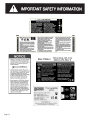
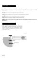
HORIZONTAL
ELECTRIC
7 TON LOG SPLITTER
MODEL NO.
ES7T20
Owner’s Manual
ASSEMBLY & OPERATING INSTRUCTIONS
Purchase Date___________________ Serial No.______________________
Dealer________________________________________________________
Boss Industrial, Inc. • 1864 High Grove Lane, Unit 116 • Naperville, IL 60540 • USA
Phone: (800) 780-BOSS (2677) • Fax (331) 472-2976
www.boss-industrial.com
Table of Contents
Page(s)
Important Safety Information ....................................................................................................................................1-6
Intended Use ...............................................................................................................................................1
Personal Protective Equipment ...................................................................................................................1
Safety Decals ...........................................................................................................................................1-4
Electrical Safety ...........................................................................................................................................5
Log Splitter Overview ...................................................................................................................................6
General Safety .............................................................................................................................................7
Work Area ....................................................................................................................................................8
Operation of the Log Splitter ........................................................................................................................8
Maintenance Safety .....................................................................................................................................9
Hydraulic Safety .........................................................................................................................................10
Fire Prevention ...........................................................................................................................................10
Assembly Instructions ............................................................................................................................................11-12
Pre-Operation Instructions ..........................................................................................................................12
Operating Instructions ............................................................................................................................................13-14
Transportation .............................................................................................................................................14
Storage ........................................................................................................................................................14
Maintenance ...........................................................................................................................................................15-16
Troubleshooting ...........................................................................................................................................................17
Technical Specifications ..............................................................................................................................................18
Exploded Diagram & Parts List ...............................................................................................................................19-21
Warranty Information ...................................................................................................................................................22
Packing List .................................................................................................................................................................23
WARNING: Read and thoroughly understand all instructions and safety information before assem- bling
or operating this log splitter. Failure to do so may cause serious injury or death. Do not allow anyone to
operate this log splitter who has not read this manual. As with all power equipment, a log splitter can be
dangerous if assembled or used improperly. Do not operate this log splitter if you have doubts or
questions concerning safe operation. Call our customer service department at 1-800-780-2677 to
address these concerns.
Si no entiende ingles, se prefiere que busque alguien que interprete las instrucciones para usted.
This safety alert symbol identifies important safety messages in this manual.
Failure to follow this important safety information may result in serious injury
or death.
INTENDED USE
INTENDED
USE
NEVER use this log splitter for any purpose other than splitting wood. It is designed for this use only. Any other use can
cause serious injury or death.
PERSONAL
PROTECTIVE
EQUIPMENT
PROTECTIVE
EQUIPMENT
BEFORE operating this log splitter make sure that you wear safety gear such as goggles or safety glasses, steel toed
shoes and tight fitting gloves (without loose cuffs or draw strings). Always wear a protective hearing device when operating
this log splitter.
NEVER wear loose clothing or jewelry that can be caught by moving parts of the log splitter. Keep clothing and hair away
from all moving parts when operating this log splitter.
SAFETY DECALS
SAFETY
DECALS
Make sure that all safety warning decals are in good condition and readable. Always replace missing or defaced decals.
Contact Boss Industrial, Inc. at 1-800-780-2677 for replacement decals.
Page | 1
Page | 2
Some of the following symbols may be used on this tool. Please study them and learn their meaning. Proper
interpretation of these symbols will allow you to operate the tool better and safer.
SYMBOL
NAME
DESIGNATION/EXPLANATION
V
Volts
Voltage
A
Amperes
Current
Hz
Hertz
Frequency (cycles per second)
W
Watt
Power
Minutes
Time
Alternating Current
Type of current
Direct Current
Type or a characteristic of current
No Load Speed
Rotational speed, at no load
Class II Construction
Double-insulated construction
Per Minute
Revolutions, strokes, surface speed, orbits etc., per minute
Wet Conditions Alert
Do not expose to rain or use in damp locations.
Read The Operator’s Manual
To reduce the risk of injury, user must read and understand
operator’s manual before using this product.
Eye, Face & Ear Protection
Always wear safety goggles or safety glasses with side shields,
earplugs and a face shield when operating this product.
Safety Alert
Precautions that involve your safety.
Wear Gloves
Always wear nonslip, heavy-duty protective gloves when
operating this product.
Wear Safety Footwear
Always wear nonslip safety footwear when operating this product.
Keep Bystanders Away
Always keep bystanders at least 25 ft. (7.5 m) away.
Keep Hands Away
Always keep hands away from the wedge and the ram.
Pinch Point
Never touch the cylinder bed, ram, or wedge during machine
operation.
Rotating & Moving Parts Alert
Beware of rotating and moving parts, serious injury could occur.
Electric Shock Alert
Never touch damaged or exposed wires while the machine is
connected to a power source.
min
no
.../min
Page | 3
The following signal words and meanings are intended to explain the levels of risk associated with this product.
SYMBOL
SIGNAL
MEANING
DANGER:
Indicates an imminently hazardous situation, which, if not avoided, will result
in death or serious injury.
WARNING:
Indicates a potentially hazardous situation, which, if not avoided, could result
in death or serious injury.
CAUTION:
Indicates a potentially hazardous situation, which, if not avoided, may result in
minor or moderate injury.
CAUTION:
(Without Safety Alert Symbol) Indicates a situation that may result in property
damage.
WARNING:
SERVICE & REPAIR
Servicing requires extreme care and knowledge and should
be performed only by a qualified service technician. For
service we suggest you return the product to your nearest
AUTHORIZED SERVICE CENTER for repair. When
servicing, use only identical replacement parts.
To avoid serious personal injury, do not attempt to use
this product until you read thoroughly and understand
completely the operator’s manual. If you do not
understand the warnings and instructions in the
operator’s manual, do not use this product. Call Boss
Industrial customer service for assistance.
WARNING:
The operation of any power tool can result in foreign objects being thrown into your eyes, which can
result in severe eye damage. Before beginning power tool operation, always wear safety goggles or
safety glasses with side shields and, when needed, wear a full face shield and earplugs. We
recommend a Wide Vision Safety Mask for use over eyeglasses or standard safety glasses with side
shields. Always use eye protection which is marked to comply with ANSI Z87.1.
SAVE THESE INSTRUCTIONS
Page | 4
ELECTRICALCONNECTION
CONNECTION
ELECTRICAL
ELECTRICAL SAFETY
EXTENSION CORDS
Use only 3-wire extension cords that have 3-prong
grounding plugs and 3-pole receptacles that accept the
tool's plug. When using a power tool at a considerable
distance from the power source, use an extension cord
heavy enough to carry the current that the tool will draw. An
undersized extension cord will cause a drop in line voltage,
resulting in a loss of power and causing the motor to
overheat. Use the chart provided below to determine the
minimum wire size required in an extension cord. Only
round jacketed cords listed by Underwriter's Laboratories
(UL) should be used.
**Ampere rating (on tool faceplate)
0-2.0
2.1-3.4
Cord Length
3.5-5.0
5.1-7.0
SPEED AND WIRING
The speed is not constant and decreases under a load or
with lower voltage. For voltage, the wiring in a shop is as
important as the motor’s horsepower rating. A line intended
only for lights cannot properly carry a power tool motor.
Wire that is heavy enough for a short distance will be too
light for a greater distance. A line that can support one
power tool may not be able to support two or three tools.
7.1-12.0 12.1-16.0
GROUNDING INSTRUCTIONS
Wire Size (A.W.G.)
25'
16
16
16
16
14
14
50'
16
16
16
14
14
12
100'
16
16
14
12
10
—
**Used on 12 gauge - 20 amp circuit.
NOTE: AWG = American Wire Gauge
When working with the tool outdoors, use an extension
cord that is designed for outside use. This is indicated by
the letters "WA" on the cord's jacket.
Before using an extension cord, inspect it for loose or
exposed wires and cut or worn insulation.
WARNING:
Keep the extension cord clear of the working area.
Position the cord so that it will not get caught on lumber,
tools or other obstructions while you are working with a
power tool. Failure to do so can result in serious
personal injury.
WARNING:
Check extension cords before each use. If damaged
replace immediately. Never use tool with a damaged
cord since touching the damaged area could cause
electrical shock resulting in serious injury.
Page | 5
This tool is powered by a precision built electric motor. It
should be connected to a power supply that is 115 volts,
60 Hz, AC only (normal household current). Do not
operate this tool on direct current (DC). A substantial
voltage drop will cause a loss of power and the motor will
overheat. If the product does not operate when plugged
into an outlet, double check the power supply.
In the event of a malfunction or breakdown, grounding
provides a path of least resistance for electric current to
reduce the risk of electric shock. This tool is equipped with
an electric cord having an equipment-grounding
conductor and a grounding plug. The plug must be
plugged into a matching outlet that is properly installed
and grounded in accordance with all local codes and
GROUNDING
INSTRUCTIONS
ordinances.
In
malfunction
grounding
Dothe
not event
modifyofthea plug
provided.orIf breakdown,
it will not fit the
outlet,
provides
path of
leastinstalled
resistance
electric electrician.
current to
have the aproper
outlet
by aforqualified
reduce
the risk
of electric shock.
This equipment-grounding
tool is equipped with
Improper
connection
of the
an
electric
cord
having
an
equipment-grounding
conductor
conductor can result in a risk of electric shock.
The
and
a
grounding
plug.
The
plug
must
be
plugged
into is
a
conductor with insulation having an outer surface that
yellow stripes
the grounded
equipmentmatching
that is properly
installedisand
in
green withoutlet
or with-out
grounding conductor.
repair
replacement of the
accordance
with all localIfcodes
andorordinances.
electric
cord
or
plug
is
necessary,
do
connect
the
Do not modify the plug provided. If it will not
not fit
the outlet,
to
a
live
terminal.
equipment-grounding
conductor
have the proper outlet installed by a qualified electrician.
Check with
a qualifiedofelectrician
or service personnel
if the
Improper
connection
the equipment-grounding
conductor
grounding
not completely
or if
can
result instructions
in a risk of are
electric
shock. Theunderstood,
conductor with
in doubt as
to whether
thesurface
tool is properly
grounded.
insulation
having
an outer
that is green
with or withRepair
or stripes
replace isa the
damaged
or worn cord immediately.
out
yellow
equipment-grounding
conductor. If
This tool
intended for of
usethe
on aelectric
circuit that
outlet
repair
or isreplacement
cordhas
or an
plug
is
like the one do
shown
Ensure
the outlet has a
necessary,
not below.
connect
the that
equipment-grounding
grounding to
pin.
conductor
a live terminal.
Check with a qualified electrician or service personnel if the
grounding instructions are not completely understood, or if
in doubt as to whether the tool is properly grounded.
Repair
or
replace
a
damaged
or
worn
cord
LOG SPLITTER OVERVIEW
(FIGURE 1).
1.
2.
3.
4.
5.
6.
7.
Page | 6
End wedge
Sliding ram
Support legs, log holder
Machine body / Oil reservoir
Control handle
115v motor
Motor control box
8. On/Off switch
9. Electrical cable with plug
10. Oil drain bolt with dipstick
11. Vent plug
12. Towing handle (DO NOT touch
during operation)
13. Wheel
IMPORTANT SAFETY INFORMATION
GENERAL SAFETY
Failure to follow these instructions may result in serious injury or death.
ALWAYS read the operator’s manual before operation.
NEVER allow children to operate this log splitter. NEVER allow adults lacking proper instructions and
understanding to operate this log splitter.
KEEP all people and pets a minimum of 25 feet away from your work area when operating this log splitter.
Only the operator is to be near the log splitter during use.
ALWAYS wear safety glasses.
NEVER activate the control until all people are clear of the work area.
NEVER use in an explosive atmosphere.
GUARD against electrical shock by preventing body contact with grounded surfaces. For example: pipes,
radiators, ranges, refrigerator enclosures.
KEEP guards in place and in good working order.
USE the proper extension cord. Make sure your extension cord is in good condition.
NEVER operate the log splitter when under the influence of alcohol, drugs or medication.
NEVER allow a person who is tired or otherwise not alert to operate the log splitter.
USE only an electrical circuit having adequate capacity as recommended by the log splitter manufacturer.
“BLOWING” a fuse or tripping a circuit breaker is usually a warning that you are overloading the machine or
have too many devices taking power from the circuit, or both. Do NOT install a higher capacity fuse!
PREPARATION OF THE LOG
Page | 7
WORK AREA
NEVER operate the log splitter on slippery, wet, muddy or icy ground.
ONLY operate your log splitter on level ground. Operating on a slope could cause the log splitter to roll over or
logs to fall off.
NEVER attempt to move your log splitter over hilly or uneven terrain.
ALWAYS block the wheels to prevent movement of the log splitter while in operation.
NEVER leave tools or pieces of wood on the tool while it is in operation.
ONLY operate your log splitter in daylight or under good artificial light.
ALWAYS keep the work area clean. Remove split wood around your log splitter immediately so that you don’t
stumble over it.
OPERATOR ZONE
ONLY operate the log splitter from the operator zone as shown
in the diagram. The operator has the safest and most efficient
access to the control valve and the beam in this location.
Failure to operate the log splitter in this position can result in
serious injury or death.
(FIGURE 2).
Operator Zone
Page | 8
KNOW how to stop the log splitter and disengage the controls before operating it.
NEVER place hands or feet between the log and splitting wedge during forward or reverse stroke. Serious
injury or death could result.
NEVER straddle or step over the log splitter during operation. NEVER reach or bend over the log splitter to
pick up a log. NEVER try to split two logs on top of each other.
NEVER try to cross split a log.
NEVER attempt to load your log splitter when the ram or wedge is in motion.
ALWAYS use your hand to operate the control lever on the valve. NEVER use your foot, a rope or any
extension device.
NEVER move the log splitter while the motor is running. Shut off the motor even if you are leaving the log
splitter for a short period of time.
MAINTENANCE SAFETY
NEVER operate your log splitter when it is in poor mechanical condition or in need of repair. Periodically
check that all nuts, bolts, screws, hydraulic fittings and hose clamps are tight.
NEVER alter your log splitter in any manner under any circumstances. Such alterations may cause your log
splitter to be unsafe and will void the warranty.
ALWAYS unplug from the power source while repairing or adjusting the splitter.
Perform all recommended maintenance procedures before using your log splitter. Replace all damaged or
worn parts immediately.
NEVER tamper with the motor to run it at excessive speeds. The maximum motor speed is preset by the
manufacturer and is within safety limits.
ALWAYS check the level of hydraulic oil before operation.
ALL replacement parts must meet manufacturer’s specifications.
Page | 9
HYDRAULIC SAFETY
The hydraulic system of your log splitter requires careful inspection along with the mechanical parts. Be sure
to replace frayed, kinked, cracked or otherwise damaged hydraulic hoses or hydraulic components.
NEVER check for leaks of hydraulic fluid with your hand. Fluid escaping from a small hole can be almost invisible.
Escaping fluid under pressure can have sufficient force to penetrate skin causing serious personal injury or even
death. Leaks can be detected by passing a piece of cardboard over the suspected leak and looking for discoloration.
ALWAYS seek professional medical attention immediately if injured by escaping hydraulic fluid. Serious infection
or reaction can develop if proper medical treatment is not administered immediately.
ALWAYS be sure to relieve all pressure by shutting off the motor and moving the control handle back to stop
position.
NEVER remove the vent plug from the hydraulic tank or reservoir while the log splitter is running. The tank could
contain hot oil under pressure which could result in serious injury.
NEVER adjust the hydraulic valve. The pressure relief valve on your log splitter is preset at the factory. Only a
qualified service technician should perform this adjustment.
FIRE PREVENTION
FIRE
NEVER operate your log splitter near a flame or spark. Hydraulic oil is flammable and can explode.
NEVER smoke while operating or refueling your log splitter. Gas fumes can easily explode.
ALWAYS take a Class B fire extinguisher with you when operating this log splitter in dry areas as a
precautionary measure against possible flying sparks.
Page | 10
UNPACKING & ASSEMBLY
\UNPACKING
This product has been shipped pre-assembled (see FIGURE 3).
• Carefully remove the log splitter and all accessories from the box. Make sure that all items listed in the
packing list are included.
• Inspect the tool carefully to make sure no breakage or damage occurred during shipping.
• Do not discard packing materials until you have carefully inspected and satisfactorily operated the tool.
• If any parts are damaged or missing, please call 1-800-780-2677 for assistance.
• Screw the control handle lever into handle bracket before operation (see FIGURE 3).
(FIGURE 3).
WARNING:
If any parts are damaged or missing, do not operate this tool until the missing parts are replaced. Failure to do so
could result in possible serious personal injury.
WARNING:
Do not attempt to modify this tool or create accessories not recommended for use with this tool. Any such alteration or
modification is misuse and could result in a hazardous condition leading to possible serious personal injury.
WARNING:
Do not connect to power supply until assembly is complete. Failure to comply could result in accidental starting and
possible serious personal injury.
Page | 11
PRE-OPERATION INSTRUCTIONS
WARNING:
Do not allow familiarity with tools to make you careless. Remember that a careless fraction of a second is
sufficient to inflict serious injury.
Log preparation: Logs should be cut with square ends.
Never split logs larger than 10 in. diameter or 20-1/2 in.
long. Uneven logs (e.g. knotted, curved, etc.) should not be
used.
Oil the wedge and upper side of the machine body. This
will allow the log to move smoothly on the surface (see
highlighted parts on FIGURE 4.).
WARNING:
Always wear safety goggles or safety glasses with side
shields when operating this tool. Failure to do so could
result in objects being thrown into your eyes resulting in
possible serious injury.
(FIGURE 4).
WARNING:
Do not use any attachments or accessories not
recommended by the manufacturer of this tool. The use
of attachments or accessories not recommended can
result in serious personal injury.
BEFORE USING THE LOG SPLITTER
•
•
•
•
•
•
Always block the wheels to prevent movement of the
log splitter while in operation.
Clear the work area.
Check that all nuts, bolts and hydraulic fittings are tight
to be sure the equipment is in a safe working condition.
Make sure your outlet type, voltage, and frequency
match the data stated on the serial number label (or
“Technical Specifications” in this manual).
Check that the switch, power cable and plug are not
damaged (no cracks, etc.) to prevent the risk of electric
shock or a short circuit.
Wear non-slip safety shoes, safety goggles, safety
gloves, protective hair covering and suitable work
clothing. Never wear jewelry, necktie and other loose
clothing.
Loosen the hydraulic vent plug to release any trapped air
that may have accumulated during shipping. Operate the log
splitter for several cycles to repel the air. Do not move the
splitter while the vent plug is loosened as the hydraulic fluid
could spill out. Air must flow in and out of the oil tank during
operation to prevent the seals in the hydraulic system from
rupturing. Refer to the oil tag for further details.
NOTE: Failure to loosen the hydraulic vent prior to operation
of this product may cause abnormal splitting or the seals in
the hydraulic system to blow out. Blown seals could cause
permanent damage to the log splitter.
Page | 12
Always check the oil level before you start the log splitter.
To check the oil level:
•
•
•
•
•
•
•
Unplug the log splitter, and screw off the control
handle lever
Using the lift handle, stand the log splitter on the
wheels end, with a block under position shield. Do
not stand on the control handle, which will damage
the valve core. (see FIGURE 8).
Using a 6mm hex key, remove the oil drain bolt.
Wipe the dipstick clean then reinsert it back into
the oil tank.
Remove the dipstick and check to see if the oil
level is between the first and second groove on the
dipstick (see FIGURE 7).
If there is not enough oil in the oil tank, add oil until
the proper level is reached.
If there is the proper amount of oil in the oil tank,
wipe the dipstick clean then replace it in the oil tank
and tighten the oil drain bolt securely.
NOTE: See “Replacing Hydraulic Oil” in the Maintenance
section for recommended oil type.
OPERATING INSTRUCTIONS
1.
2.
3.
4.
5.
Plug the unit into a 3 prong outlet.
Press the power button to turn the log splitter on.
Place the log firmly against one of the wedges.
Move control handle down to split the log.
Release the handle to retract the ram
automatically and begin loading the next log.
When the machine is no longer in use, switch it
off and unplug the power cable.
(FIGURE 5).
NOTE:
a) Ensure that the horizontal distance between the
splitter and outlet is more than 5 feet.
b) Load each log by grasping the rounded sides of
the log only.
c) Only allow responsible adults who have read and
understand the manual to operate this machine.
d) Be familiar with all controls and proper operation. Know how to stop the machine quickly in the event of an emergency.
e) Do not operate the machine while under the influence of alcohol, drugs or medication.
f) Only a single operator is allowed to load and operate this log splitter. Keep bystanders, helpers, pets and children a
sufficient distance, at least 25 feet from the machine.
g) Only use your hands to operate the control handle and the switch. Arms, feet, knees, rope, heavy objects and extension
device are not allowed.
h) Never put any part of your body between the extending ram and the wedge.
i)
Don’t step over the log splitter when the motor is running.
j)
Always split log along its grain. If it is cut against the grain, there is potential for the wood to burst or fly out resulting in
injury.
k) Don’t force the tool. It is already designed to operate at its maximum speed and tonnage. If you experienced
problems splitting especially hard wood, do not continue to push on the control handle for more than 3
seconds. Release the control handle at once to avoid damage. If the motor stops, turn off the motor and then
turn it back on again to continue operation.
l)
If the log is clipped or jammed on the wedge, release the control handle and unplug the power cable immediately.
Gently knock off the log with a hammer or mallet (not with your hands).
m) Never attempt to split more than one log at a time unless the ram has fully extended and a second log is needed to
complete the separation of the first log. Never attempt to split one log on top of another.
n) Regularly clear the split wood to keep the work area clear of debris.
o) Periodically check that all nuts, bolts, screws, hydraulic fittings and hose clamps are tightened.
p) Never operate your splitter on wet, muddy or icy surfaces. Safe footing is essential in preventing accidents.
q) Never leave the machine unattended while the motor is running.
r) Never use this machine in a damp or rainy environment.
s) Only operate the log splitter when there is sufficient lighting.
t) Never tamper with the motor to run it at excessive speeds. The maximum motor speed is preset by the manufacturer
and is within safety limits.
u) Switch off and unplug the power cable if the machine malfunctions. For example: if the machine makes loud noises and
the ram is running erratically, there is a strong possibility that there is excessive air in the hydraulic lines or there is a
shortage of hydraulic oil in the tank (refer to the Troubleshooting section for the solution).
v) Do not pull on the power supply cable to unplug the machine.
Page | 13
SPLITTING LOGS
See FIGURE 5.
Always place logs lengthwise on the work table and resting
firmly on the side supports with one end against the wedge.
Place logs flat and in the direction of the grain. Never angle
the log to split it or place the log crosswise on the splitter.
Never split more than one log at a time.
•
•
•
WARNING:
Never keep pressure on the wood by trying to force the
log splitter for more than three seconds. After five
seconds, the oil will heat up and could damage the tool.
Place log lengthwise and lying flat on the work
table.
Both ends of the log should be cut as square
as possible to help prevent the log from riding
out of the splitter during operation.
Do not split logs greater than 20.5 inches
in length.
NOTE: If the log is small, place it against the wedge before
starting the splitter.
TRANSPORTATION
•
•
•
This machine can fit in most vehicles for transportation.
Ensure that the splitter is properly secured before the vehicle is in motion.
Ensure vent plug is tightened, and that all hydraulic fittings are tight to avoid leaking oil.
NOTE:
a)
b)
c)
d)
Never move this machine while the motor is running.
Be extra cautious when moving this machine on rugged and rough terrain.
Store the machine upright so and ensure that it cannot be tipped over during transport.
Never allow anyone to ride on the machine while transporting.
STORAGE
NOTE:
a)
b)
c)
d)
e)
Store this unit switched off and unplugged.
Allow machine to cool 5 minutes after every use before storing.
Protect power supply cable from heat, sunshine, aggressive liquids and sharp edges.
Store unit in a clean, dry area. Do not store in unprotected areas outdoors.
Never place near corrosive materials or in a damp environment.
Do not allow children near the splitter.
Page | 14
MAINTENANCE
WARNING:
When servicing, use only identical replacement parts.
Use of any other parts may create a hazard or cause
product damage.
REPLACING HYDRAULIC OIL
See FIGURES 6, 7, 8, 9.
The hydraulic oil in the log splitter should be changed every
100 hours of use.
•
•
WARNING:
Only the parts shown on the parts list are intended to be
repaired or replaced by the customer. All other parts
should be replaced at an Authorized Service Center.
•
•
GENERAL MAINTENANCE
Avoid using solvents when cleaning plastic parts. Most
plastics are susceptible to damage from various types of
commercial solvents and may be damaged by their use.
Use clean wipes to remove dirt, dust, lubricant, grease, etc.
WARNING:
Do not at any time let brake fluids, gasoline, petroleumbased products, penetrating lubricants, etc., come in
con- tact with plastic parts. Chemicals can damage,
weaken or destroy plastic which may result in serious
personal injury.
SHARPENING THE WEDGE
After using the log splitter for some time, it may be
necessary to sharpen the wedge. Using a fine-toothed file,
smooth any burrs or crushed areas along the cutting edge.
LUBRICATION
All of the bearings in this tool are lubricated with a sufficient
amount of high grade lubricant for the life of the unit under
normal operating conditions. Therefore, no further
lubrication is required on the bearings.
Page | 15
•
•
•
•
Unplug the log splitter.
Position the log splitter so that the oil drain bolt is
positioned lower than the opposite side of the
machine. Ensure that the log splitter is tilted to an
angle of at least 30 degrees. The log splitter should
be placed securely.
Using a 6mm hex key, remove the oil drain bolt and
disconnect the vent plug.
Drain the hydraulic oil from the oil tank into a
container of no less than four liter capacity.
Once the oil has drained from the oil tank, turn the
log splitter on the end with the wheels.
Refill the oil tank with fresh hydraulic oil (3.8 liters or
4 quarts).
Place the cleaned dipstick into the oil tank. Remove
and check the oil level.
Level down the log splitter, start the motor and cycle
the ram several times to remove excess air from the
reservoir.
NOTE: The oil level should be between the two grooves
around the bottom of the dipstick as shown in FIGURE
7.
•
•
•
•
Use AW32 hydraulic fluid.
Replace oil drain bolt. Tighten securely.
Dispose old oil at an oil recycling center.
Refer to the oil tag for additional details.
FIGURE 6.
FIGURE 7.
Drain Oil from Reservoir
FIGURE 8.
Place Log Splitter In Vertical Position
Page | 16
Note Acceptable Oil Fill Level
FIGURE 9.
Remove U-Joint and Refill Oil to Desired Level
TROUBLESHOOTING
Problem
Possible Cause
Solution
Motor fails to start.
•
Overload Protection Device
is disengaged to protect the
log splitter from being
damaged.
•
Switch off the motor and
unplug the power cable. Let
motor cool down for half an
hour and restart. If this does
not solve the problem, call
your dealer for customer
support.
The log splitter won’t split logs.
•
•
Log is improperly positioned.
The size or hardness of the
log exceeds the machine’s
capacity.
Wedge cutting edge is blunt.
Insufficient hydraulic oil.
Unauthorized adjustment
was made on the Maximum
Pressure Limiting Screw.
Lower maximum pressure
rating was set.
•
Refer to Operation section
for log loading.
Reduce the log size before
splitting
Refer to “Sharpening The
Wedge” in the Maintenance
section.
Locate leak(s). Contact the
dealer.
Contact the dealer.
Unit is not placed on level
ground.
Lack of hydraulic oil
Excessive air in the
hydraulic system.
Log splitter is over forced.
•
•
•
•
Log ram jerks, vibrates or does not
move.
•
•
•
•
•
•
•
•
•
•
Oil leaks from the hydraulic system
or from other points.
•
•
•
•
Page | 17
Air is sealed in hydraulic
system while operating.
Vent plug is not tightened
before moving the log
splitter.
Oil drain bolt is not tight.
Hydraulic fitting(s) and/or
seal(s) are worn.
•
•
•
•
•
•
Reposition the log splitter
to ensure that the wheel
end of the unit is no
higher than the other end.
Check oil level for possible
oil refilling.
Ensure vent plug is loose
during operation
Turn off and restart the unit.
Contact the dealer.
Loosen vent plug before
operating the log splitter.
Tighten the vent plug before
moving the log splitter.
Tighten the oil drain bolt.
Contact the dealer.
TECHNICAL SPECIFICATIONS
Electrical requirements
115V, 60Hz
Power output
1500W
Rated current
13.5A
Motor speed
3400 RPM
Power cable
SJTW 14 AWG (2.08mm²)
Max splitting force
7 ton
Max splitting length
20.5 in
Max splitting diameter
10 in
Hydraulic pressure
3500 PSI
Cylinder bore
2.2 in
Feed
9 sec
Retract
5 sec
Cycle time
Max cylinder stroke
17 in
Oil capacity
3.8 L
Machine dimensions (L×W×H) (in)
Machine net weight
Page | 18
39.5x13.5x20
106 lbs
EXPLODED DIAGRAM & PARTS LIST
Page | 19
REF #
PART #
PART NAME
SPECIFICATIONS
QTY PER SECTION
1
310-325
Machine Body w/ End Wedge
1
2
530-101
Ram Cap & Shaft
1
3
530-475
Upper Nylon Cushion
1
4
530-898
Lower Nylon Cushion
1
5
530-616
Base Plate of Ram
1
6
750-160
Flat Washer
M8*1
6
7
750-075
Spring Washer
M8*2.3
6
8
710-084
Inner Hex Bolt
M8*15
6
9
710-685
Double-Screw Bolt
M10*813
4
10
530-322
Cylinder Tube
Ø55*743
1
11
730-847
O Seal Ring
Ø55*3.1
12
730-446
Seal Cover
1
13
530-624
Piston Head
1
14
730-924
O Seal Ring
15
530-434
Piston Shaft w/ Connecting Plate
16
530-580
Retracting Spring
17
720-156
Nut
M14
4
18
720-884
Lock Nut
M14
2
19
730-772
Paper Seal Ring
20
730-186
O Seal Ring
21
730-139
Dirt Proof Ring
1
22
540-853
Front Reservoir Cover
1
23
730-094
O Seal Ring
Ø6*1
1
24
540-537
Vent Plug
M4*10
1
25
750-158
Copper Seal Washer
M14*1
1
26
540-333
Oil Dipstick w/ Oil Drain Bolt
1
27
520-974
Hydraulic Valve
1
28
730-198
O Seal Ring
29
750-520
Flat Washer
M10*1
4
30
750-371
Spring Washer
M10*2
4
31
720-465
Nut
M10
32
350-233
Position Shield
33
750-525
Flat Washer
M10*2
4
34
720-678
Snap Head Nut
M10
4
35
520-596
Torsion Spring
36
520-293
Control Handle Bracket
37
520-401
Control Handle Lever w/ Grip
Ø12.5*134
1
38
560-587
Oil Tube
Ø14 - Ø10*100*1
1
39
730-624
O Seal Ring
Ø18*1.9
2
40
750-158
Copper Seal Washer
M14*1
2
41
710-896
Oil Tube Screw
M14*30
2
42
710-895
Inner Hex Head Bolt
M8*20
4
43
750-160
Flat Washer
M8*1
4
44
550-203
Hydraulic Pump
45
730-624
O Seal Ring
Ø18*1.9
1
46
560-587
Oil Tube
Ø14 - Ø10*100*1
1
47
750-158
Copper Seal Washer
M14*1
3
Page | 20
Ø50*3.5
1
1
1
1
2
Ø30*2.65
Ø14*2.4
1
4
4
1
1
1
1
REF #
PART #
48
710-896
Oil Tube Screw
49
540-311
Oil Filter
50
710-541
Inner Hex Head Bolt
M8*35
4
51
750-075
Spring Washer
M8*2.3
4
52
750-160
Flat Washer
M8*1
4
53
910-234
Electric Motor
54
910-194
Fan
55
760-548
Circlip for Shaft
56
910-154
Fan Cover
Ø162
1
57
750-270
Flat Washer
M4*1
3
58
740-477
Cross Recess Pan Head Screw
M4*10
59
920-011
Connecting Box (Bottom)
1
60
920-506
Connecting Box (Rubber Ring)
1
61
920-853
Connecting Box (Cover)
62
740-603
Cross Recess Pan Head Screw
63
920-943
Power Switch
64
920-980
Capacitor
65
930-154
Cable Fastener Nut
1
66
930-807
Cable Fastener
1
67
930-233
Cable Fastener Bolt
1
68
930-511
Cable Bushing
69
930-182
Power Cable
70
320-812
Front Leg
71
740-526
Cross Recess Pan Head Screw
M8*55
4
72
750-638
Flat Washer
M8*1
4
73
720-500
Lock Nut
M8
4
74
750-525
Flat Washer
M10*2
2
75
720-678
Snap Head Nut
M10
2
76
320-666
Front Support Bar Bushing
Ø16*114
1
77
320-563
Front Support Bar
Ø12.7*196
1
78
320-825
Bumper
79
710-690
Hex Head Bolt
M8*55
2
80
750-638
Flat Washer
M8*1
4
81
320-414
Joint Leg and Log Holder
82
720-500
Lock Nut
M8
2
83
740-526
Cross Recess Pan Head Screw
M8*55
4
84
750-638
Flat Washer
M8*1
4
85
720-500
Lock Nut
M8
4
86
320-748
U Shape Towing Handle
87
340-090
Wheel Axle
Ø12.7*336
1
88
340-250
Axle Bushing
Ø16*165
1
89
750-146
Flat Washer
M13*2
2
90
330-214
Wheel
7’*1.8'
2
91
340-132
Bearing spacer
Ø 16*36*1.2
2
92
750-525
Flat Washer
M10*2
2
93
720-120
Lock Nut
M10
2
Page | 21
PART NAME
SPECIFICATIONS
M14*30
QTY PER SECTION
2
1
1
Ø16
1
3
1
M4*10
6
1
60uf
1
1
STJW 3/C 14AWG, Ø2.08*1600
1
2
2
2
1
WARRANTY
LIMITED WARRANTY STATEMENT
Boss Industrial, Inc., (“Boss Industrial”) warrants to the original retail purchaser that this BOSS brand outdoor product
is free from defect in material and workmanship and agrees to repair or replace, at Boss Industrial’s, discretion, any
defective product free of charge within these time periods from the date of purchase.
•
•
Two years for all models if used for personal, family, or household use;
90 days for any unit used for other purposes, such as rental or commercial.
This warranty extends to the original retail purchaser only and commences on the date of the original retail purchase.
Any part of the this product manufactured or supplied by Boss Industrial and found in the reasonable judgment of
Boss Industrial to be defective in material or workmanship will be repaired or replaced without charge for parts and
labor by a Boss Industrial authorized service center.
The product, including any defective part, must be returned to an authorized service dealer within the warranty period.
The expense of delivering the product to the dealer for warranty work and the expense of returning it back to the
owner after repair or replacement will be paid by the owner. Boss Industrial’s responsibility in respect to claims is
limited to making the required repairs or replacements and no claim of breach of warranty shall be cause for
cancellation or rescission of the contract of sale of any BOSS brand product. Proof of purchase will be required by the
dealer to substantiate any warranty claim. All warranty work must be performed by a Boss Industrial authorized
service center.
This warranty is limited to ninety (90) days from the date of original retail purchase for any Boss Industrial brand
product that is used for rental or commercial purposes, or any other income-producing purpose.
This warranty does not cover any BOSS brand product that has been subject to misuse, neglect, negligence, or
accident, or that has been operated in any way contrary to the operating instructions as specified in this operator’s
manual. This warranty does not apply to any damage to the product that is the result of improper maintenance or to
any product that has been altered or modified. The warranty does not extend to repairs made necessary by normal
wear or by the use of parts or accessories which are either incompatible with the BOSS brand product or adversely
affect its operation, performance, or durability. In addition, this warranty does not cover:
B. Tune-ups – Spark Plugs, Carburetors
Adjustments, Ignition, Filters
B. Wear items – Bump Knobs, Outer Spools, Cutting Lines, Inner Reels, Starter Pulleys, Starter Ropes, Drive Belts,
Tines, Felt Washers, Hitch Pins, Mulching Blades, Blower Fans, Blower and Vacuum Tubes, Vacuum Bags and
Straps, Guide Bars, Saw Chains
Boss Industrial reserves the right to change or improve the design of any BOSS brand product without
assuming any obligation to modify any product previously manufactured.
ALL IMPLIED WARRANTIES ARE LIMITED IN DURATION TO THE STATED WARRANTY PERIOD.
ACCORDINGLY, ANY SUCH IMPLIED WARRANTIES INCLUDING MERCHANTABILITY, FITNESS FOR A
PARTICULAR PURPOSE, OR OTHERWISE, ARE DISCLAIMED IN THEIR ENTIRETY AFTER THE EXPIRATION
OF THE APPROPRIATE TWO-YEAR, ONE-YEAR, OR NINETY-DAY WARRANTY PERIOD. BOSS INDUSTRIAL’S
OBLIGATION UNDER THIS WARRANTY IS STRICTLY AND EXCLUSIVELY LIMITED TO THE REPAIR OR
REPLACEMENT OF DEFECTIVE PARTS AND BOSS INDUSTRIAL DOES NOT ASSUME OR AUTHORIZE
ANYONE TO ASSUME FOR THEM ANY OTHER OBLIGATION. SOME STATES DO NOT ALLOW LIMITATIONS
ON HOW LONG AN IMPLIED WARRANTY LASTS, SO THE ABOVE LIMITATION MAY NOT APPLY TO YOU.
BOSS INDUSTRIAL ASSUMES NO RESPONSIBILITY FOR INCIDENTAL, CONSEQUENTIAL, OR OTHER
DAMAGES INCLUDING, BUT NOT LIMITED TO, EXPENSE OF RETURNING THE PRODUCT TO AN
AUTHORIZED BOSS INDUSTRIAL SERVICE CENTER AND EXPENSE OF DELIVERING IT BACK TO THE
OWNER, MECHANIC’S TRAVEL TIME, TELEPHONE OR TELEGRAM CHARGES, RENTAL OF A LIKE PRODUCT
DURING THE TIME WARRANTY SERVICE IS BEING PERFORMED, TRAVEL, LOSS OR DAMAGE TO
PERSONAL PROPERTY, LOSS OF REVENUE, LOSS OF USE OF THE PRODUCT, LOSS OF TIME, OR
INCONVENIENCE. SOME STATES DO NOT ALLOW THE EXCLUSION OR LIMITATION OF INCIDENTAL OR
CONSEQUENTIAL DAMAGES, SO THE ABOVE LIMITATION OR EXCLUSION MAY NOT APPLY TO YOU.
This warranty gives you specific legal rights, and you may also have other rights which vary from state to state.
This warranty applies to all BOSS brand products manufactured by or for Boss Industrial and sold in the United States
and Canada.
Page | 22
PACKING LIST
(1) Log Splitter
(1) Control handle
Page | 23
(1) Owner’s Manual
(1) Hex Key
Page | 24
Boss Industrial, Inc. • 1864 High Grove Lane, Unit 116 • Naperville, IL 60540 •
USA
Phone: (800) 780-BOSS (2677) • Fax (331) 472-2976
www.boss-industrial.com
Page | 25