1
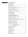
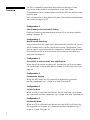
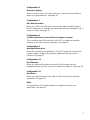
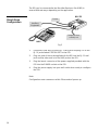
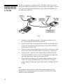
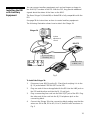
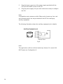
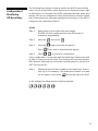
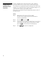
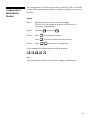
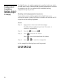
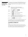
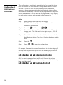
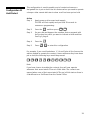
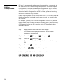
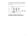
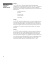
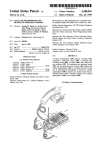
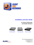
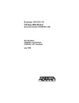
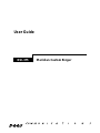
User Guide
DSI-375
Meridian Custom Ringer
Introduction
Dees developed the DSI-375, Meridian Custom Ringer, in conjunction
with Northern Telecom. The DSI monitors the DMS-100™ or SL-100™
digital Centrex lines servicing Meridian™ Business Sets (MBS).
The DSI is equipped with a variable frequency electronic ringer and the
ability to close a set of contacts which can be used to control auxiliary
equipment such as aloud ringer or lamp. The DSI will customize the
ringing performance and enhance the functionality of your MBS.
Table of Contents
Part 1 - Application Overview
Specifications ........................................................................................................2
Part 2 - Getting Started
The Meridian Business Set .................................................................................6
Default Settings .....................................................................................................6
Programming the DSI ...........................................................................................6
When to Apply Power to the DSI .......................................................................7
What to Do If You Make a Mistake While Programming ...............................7
Deactivating a Configuration...............................................................................7
How to Erase Everything and Start Again ........................................................7
How Many lines You Can Monitor......................................................................7
Understanding Day Service and Night Service...............................................7
About DSI's Memory ............................................................................................7
Programming the DSI with the CTA-369 or CRI-376 ........................................8
Part 3 - Installing the DSI
Stand Alone Configuration.................................................................................10
T Adapter Configuration.....................................................................................11
Part 4 - Adding Auxiliary Equipment
Installing the DSI with the CTA-369 or CRI-376..............................................14
Installing the DSI with Auxiliary Equipment ...................................................15
Part 5 - Programming the DSI
Configuration 0: Clear Memory or Factory Default Setting .........................18
Configuration 1: Monitoring Off Hook Busy ....................................................19
Configuration 2: Second Call or Intercom Alert Tone Amplification ..........20
Configuration 3: Simultaneous Ringing ...........................................................21
Configuration 4: Set Idle On-Hook....................................................................22
Configuration 5: Set Busy Off-Hook .................................................................23
Configuration 6: Distinctive Ringing.................................................................24
Configuration 7: MBS Add-On Module............................................................25
Configuration 8: Controlling Auxiliary Contacts
(External Ringers or Lamps) ...............................................26
Configuration 9: Message Waiting Alert.........................................................27
Configuration 10: Hold Reminder......................................................................28
Configuration 11: Hold Detect ...........................................................................29
Linking Configurations........................................................................................30
Part 6 - Operation
Operating the DSI day to day ............................................................................34
Operating Night Service.....................................................................................35
Part 7 - Miscellaneous
Specifications ......................................................................................................38
Warranty Information .........................................................................................39
Regulatory Notes.................................................................................................40
Other Dees Centrex Enhancements.................................................................42
Part 1
Application Overview
Overview
The DSI is capable of performing many different functions. These
functions are described as configurations in this User Guide.
Configurations can be linked together so that the DSI can perform more
than one task.
Each configuration is described briefly here. More detailed explanations
are located on pages 18-29.
Configuration 0
Clear Memory or Factory Default Setting
Clears all previous programming and returns DSI to its factory default
setting. See page 18.
Configuration 1
Monitoring Off-Hook Busy
Used to monitor an "off-hook" state. When detected, the DSI will close a
set of contacts which can be used to light a lamp. Configuration 1 can
also be used in conjunction with the "make busy" feature of the Meridian
Business Set so that a set of contacts will close when this feature is
activated. See page 19.
Configuration 2
Second Call or Intercom Alert Tone Amplification
When there is a second incoming call, an intercom call or a ring again
call on the MBS or associated add-on module, the DSI rings once. See
page 20.
Configuration 3
Simultaneous Ringing
When the MBS rings, the DSI rings and activates any connected
auxiliary equipment, e.g., a ringer or a lamp. See page 21.
Configuration 4
Set Idle On-Hook
When an LCD on selected lines flashes, the DSI rings and can activate
any connected auxiliary equipment, e.g., a ringer or a lamp. See page 22.
Configuration 5
Set Busy Off-Hook
When an LCD on selected lines flashes while the MBS is off-hook, the
DSI rings and can activate any connected auxiliary equipment, e.g., a
ringer or a lamp. See page 23.
2
Configuration 6
Distinctive Ringing
Sets your DSI to ring with a distinctive tone. Choose from ten different
tones or ringing cadences. See page 24.
Configuration 7
MBS Add-On Module
When any LCD on the MBS and its associated add-on module flashes,
the DSI rings and can activate any connected auxiliary equipment, e.g., a
ringer or a lamp. See page 25.
Configuration 8
Controlling Auxiliary Contacts (External Ringers or Lamps)
This is used to control the contacts in the DSI. It enables or disables
contacts to activate auxiliary equipment. See page 26.
Configuration 9
Message Waiting Alert
When the message waiting button is lit, the DSI rings with a distinctive
cadence and/or activates the auxiliary equipment through a set of
contacts. See page 27.
Configuration 10
Hold Reminder
When any selected lines have been left on Hold longer than the
programmed time, the DSI rings with a distinctive cadence. See page 28.
Configuration 11
Hold Detect
When any selected lines are on Hold, the DSI activates the auxiliary
equipment. See page 29.
Note:
Configurations can be linked together to support more than one
application. See page 30.
3
4
Part 2
Getting Started
This section contains important information about installing and
programming the DSI.
The Meridian
Business Set
(MBS)
The following illustration shows the dial pad on the MBS that is used to
operate and set up the DSI. The line buttons that are referenced in the
procedures in this User Guide are also shown. Line button 1 is always
the Primary Directory Number (PDN).
Line button 6
Line button 5
Line button 4
Line button 3
Line button 2
MBS
Line button 1
Primary Directory Number
(PDN)
Fig. 1
Default Settings
When the DSI leaves the factory, the DSI and the DSI ringer are already
switched on, ready to operate in Day Service mode when power is
applied.
Programming
the DSI
Programming the DSI involves identifying what you require the DSI to do
and then inputting a simple program sequence. To program the DSI
always use the dial pad on the MBS with the handset on-hook. Do not
use the line buttons.
Before you start to program, we suggest that you write down the
configuration string so that input via the dial pad is streamlined.
Always test the input program by calling the DSI's host set from another
telephone.
Applications for which the DSI may be used are described in the next
section and one or more configurations may be linked together. See
Linking Configurations on page 30 for examples and methods.
6
When to Apply
Power to the DSI
What to Do If
You Make a
Mistake While
Programming
Deactivation a
Configuration
How to Erase
Everything and
Start Again
How Many Lines
You Can Monitor
The programming mode of the DSI is accessed directly after power is
applied to the unit and is identified by the rapidly flashing LED. You have
20 seconds to commence programming before the DSI times out. If you
wait longer than 20 seconds to commence programming, simply unplug
the power supply and reapply power to start again.
Follow the detailed instructions for each configuration. If a mistake is
made in an individual configuration program, beginning of that
configuration sequence. Do not forget to reapply power to the DSI before
recommencing programming.
If you wish to deactivate a single configuration once it has been entered,
follow the configuration instructions as before, but do not press 1 to
activate the feature, instead press 0 to deactivate the feature.
If you are unsure which programs are resident in the DSI, follow the
instructions outlined in Configuration 0, which will erase any programs
and return the DSI to its factory default mode.
When in Day Service mode, the DSI will monitor as many as 10 line
appearances and in Night Service mode the DSI will monitor all line
appearances including those on a multi-button add-on module.
7
Understanding
Day Service and
Night Service
About DSI's
Memory
Programming the
DSI with the
CTA-369 or the
CRI-376
8
Day Service refers to any configurations that you have programmed the
DSI to perform.
However, sometimes, different service is required at night. For this
reason the DSI provides a Night Service option. When the DSI is
operating on Night Service mode, all lines on the station and the add-on
module will ring whenever there is an incoming call.
The DSI will retain all configuration programming even if there is a
power failure or you unplug it. When power is restored, you may
continue to use your DSI as before.
You can attach the DSI and either the CTA-369 or CRI-376 to your MBS.
For more information about these models refer to the last page of this
guide.
To program the DSI with the CTA/CRI:
1.
Apply power to the DSI and program it using the dial pad of your
MBS.
2.
Disconnect power to the DSI.
3.
Apply power to the CTA/CRI and program it using the dial pad of
your MBS.
4.
Reapply power to the DSI.
Part 3
DSI Installation
The DSI can be connected to the Meridian Business Set (MBS) in
several different ways depending on the application.
DSI-375
Stand Alone
Configuration
Power
Auxiliary
Equipment
Telephone Line
or Wall Jack
MBS
Fig. 2
1.
Disconnect your MBS from the RJ-11 wall jack and plug it in to the
RJ-11 jack marked STATION SET on the DSI.
2.
Plug one end of the cord supplied with the DSl into the RJ-11 wall
jack and the other end in to the LINE jack on the DSI.
3.
Plug the barrel connector of the power supplied provided with the
DSI into the POWER socket on the DSI.
4.
Plug the power supply into your wall outlet when ready to configure
the DSI.
Note:
Configuration must commence within 20 seconds of power up.
10
Installation with
T-Adapter
This installation method can be applied when your MBS model is any of
the following:
model M5209
model M5312
Power
DSI-375
RJ-11
wall outlet
Auxiliary
Equipment
“T” Adapter
MBS
Fig. 3
1.
Disconnect your MBS from the RJ-11 wall jack and plug it in to the
RJ-11 jack marked STATION SET on the DSI.
2.
Plug one end of the cord supplied with the DSI into the T-adapter
and the other end into the LINE jack on the DSI.
3.
Plug the barrel connector of the power supplied provided with the
DSI into the POWER socket on the DSI
4.
Plug the power supply into you wall outlet when ready to configure
the DSI.
Note:
Configuration must commence within 20 seconds of power up.
11
12
Part 4
Adding Auxiliary Equipment
Installing the DSI
with the CTA-369
or CRI-376
The DSI can operate in tandem with the CTA-369 or CRI-376. For more
information about these products see the last page of this guide. The two
units must be programmed separately and are connected together via
the LINE jack on the DSI.
Power
Power
DSI-375
Auxiliary
Equipment
CRI-376 or
CTA-369
Telephone Line
or Wall Jack
MBS
Fig. 4
1.
Disconnect your MBS from the RJ-11 wall jack and plug it in to
RJ-11 jack marked STATION SET on the DSI.
2.
Plug one end of the cord supplied with your DSI into the LINE jack
on your DSI and plug the other end of this cord into the STATION
SET plug on the CTA or CRI.
3.
Plug one end of the cord supplied with the CTA or CRI into the LINE
jack on the CTA or CRI and the other end into the RJ-11 wall jack.
4.
Plug the barrel connector of the power supply provided with the
DSI into the POWER socket on the DSI. Plug the power supply into
your wall outlet when ready to configure the DSI.
5.
Plug the barrel connector of the power supply provided with the
CTA or CRI into the POWER socket of the CTA or CRI. Plug the
power supply into your wall outlet when ready to configure the CTA
or CRI.
Note:
Configuration must commence within 20 seconds of power up. See
Getting Started, Programming the DSI with the CTA-369 or CRI-376 on
page 8, for more information.
14
Installing the DSI
with Auxiliary
Equipment
You can connect auxiliary equipment such as loud ringers or lamps to
the AUX EQPT sockets in the DSI. With the DSI, they provide additional
signals about the status of the lines on the MBS.
The Dees Stinger 24, Model198, or Model126 is fully compatible with the
DSI.
See page 26 for instructions on how to control auxiliary equipment.
The following illustration shows how to attach the Stinger 24.
Stinger 24
Power
Volume
adjustment
control
DSI-375
RJ-11 to Screw
Terminal Jack
Telephone Line
or Wall Jack
MBS
Fig. 5
To install the Stinger 24:
1.
Disconnect your MBS from the RJ-11 wall jack and plug it in to the
RJ-11 jack marked STATION SET on the DSI.
2.
Plug one end of the cord supplied with the DSI into the LINE jack on
the DSI and the other end into the RJ-11 wall jack.
3.
Plug a connecting line cord into the AUX EQPT jack of the DSI. Plug
the other end of the cord into the RJ-11 telephone jack on the
connecting block.
4.
Connect the Stinger 24 to the connecting block making sure that the
wires are: GN to GN, RD to AD, YL to YL, and BK to BK as shown in
Fig. 5.
15
5.
Plug the barrel connector of the power supply provided with the
DSI into the POWER socket on the DSI.
6.
Plug the power supply into your wall outlet when ready to configure
the DSl.
Note:
Configuration must commence within 20seconds of power up. Line cord
and connecting block are not provided with the DSI for hooking up
auxiliary equipment.
The following illustration shows the auxiliary equipment jack in details.
Auxiliary Equipment Jack
Front View
Internal View
Fig. 6
Note:
This application conflicts with the "make busy" feature. To control AUX
EQPT output see Configuration 8.
16
Part 5
Programming the DSI
Configuration 0
Clear Memory or
Factory Default
Setting
Configuration 0 is used to clear the DSI's non-volatile memory and return
the unit to factory default setting which is as follows:
DSI on
Ringer on
Tone selection
Normal MBS
All configuration options are turned off.
Action
18
Step 1:
Apply power or disconnect and then reapply.
The LED will flash rapidly and you have 20 seconds to
commence programming
Step 2:
Press * then press 0
Step 3:
Press #
1 to enter this configuration
Configuration 1
Monitoring
Off-Hook Busy
The Off-Hook Busy feature is used to monitor the MBS for an off-hook
state. The DSI will provide contact closure once detected so that a light
or other device is activated. If the MBS is equipped with the "make busy"
feature, DSl can be configured to close those contacts when the "makebusy" feature has been activated regardless of which key on the MBS is
assigned to the "make busy" feature.
Action
Step 1:
Apply power or disconnect and then reapply.
The LED will flash rapidly and you have 20 seconds to
commence programming.
Step 2:
Press the *
Step 3:
Press the 1 again to activate the feature.
then press 1
Press 0 if you wish to deactivate this feature.
Step 4:
Press #
1
to enter this configuration.
If this configuration is to be used with the "make busy" feature, proceed
to Step 5. If not, you have finished. The contacts will close any time the
MBS goes off-hook and are connected to auxiliary devices via the AUX
EQPT jack on the DSI.
Step 5:
Determine the line button number of the "make busy" feature
(see Fig. 6). For example, if the "make busy" feature is located
on line button 4, then press 4
on the dial pad of the MBS.
In this example the following keys would be pressed:
*
1
1
4
#
1
19
Configuration 2
Second Call or
Intercom
Alert Tone
Amplification
The MBS uses a two second tone (or splash tone) to identify certain
types of calls.
For example:
A second incoming call if off-hook
An intercom call
The "ring again" feature
Sometimes this tone is not loud enough. The DSI can be configured to
provide a louder tone through its own speaker. When the DSI's internal
speaker rings, contacts will close to power auxiliary equipment
connected to the AUX EQPT jack on the DSI. Auxiliary equipment is
optional. Examples of auxiliary equipment are loud ringers or beehive
lamps.
Action
Step 1:
Apply power or disconnect and then reapply.
The LED will flash rapidly and you have 20 seconds to
commence programming.
Step 2:
Press the * then press 2
Step 3:
Press the 1 key to activate this feature.
Press 0 if you wish to deactivate this feature.
Step 4:
#
Press
1 to enter this configuration.
In this example the following keys would be pressed:
*
20
2
1
#
1
Configuration 3
Simultaneous
Ringing on
lines that are
programmed to
ring
Using Configuration 3, the DSI will ring any time any line on the MBS
rings and any associated auxiliary equipment attached to the DSl will
also be activated.
Remember, in this configuration the DSl will ring only if the lines on the
MBS are programmed to ring.
Action
Step 1:
Apply power or disconnect and then reapply.
The LED will flash rapidly and you have 20 seconds to
commence programming.
Step 2:
Press the
Step 3:
Press 1 to activate this feature.
*
and then press 3
Press 0 if you wish to deactivate this feature.
Step 4:
Press #
1 to enter this configuration.
In this example the following keys would be pressed:
*
3
1
#
1
21
Configuration 4
In this application, the DSl can be configured to ring on any line or group
of lines when the MBS is on-hook.
Set Idle On-Hook
Action
Step 1:
Apply power or disconnect and then reapply.
The LED will flash rapidly and you have 20 seconds to
commence programming.
Step 2:
Press the * and then press 4
Step 3:
On your dial pad depress the numbers that correspond with
the line keys you wish to ring. See fig. 1, page 6
Step 4:
Press #
1 to enter this configuration.
For example, to make line buttons 2, 3 and 4 to ring the following keys
would be pressed:
*
4
2
3
4
#
1
Now any call that appears on line buttons 2, 3 or 4 (normally not ringing
lines), will make the DSl ring using the standard MBS ringing cadence.
22
Configuration 5
Set Busy Off-Hook
In his application, the DSI can be configured to ring on any line or group
of lines when the MBS is off-hook or in use.
This configuration can be used to provide normal ringing instead of the
splash tone that normally identifies a second incoming call when the
user is off-hook.
Note:
This application will be very useful if you wear a headset.
Action
Step 1:
Apply power or disconnect and then reapply. The LED will
flash rapidly and you have 20 seconds to commence
programming.
Step 2:
Press the *
Step 3:
On your dial pad depress the numbers that correspond with
the line keys you wish to ring. See Fig 1, page 6.
Step 4:
Press #
then press 5
1 to enter this configuration.
For example, to make line buttons 3, 5 and 7 ring, even if the MBS is offhook, the following keys would be pressed:
*
5
3
5
7
#
1
23
Configuration 6
Distinctive Tone
Selection
The DSI is equipped with an internal electronic ringer capable of
providing 5 different tones in either single or double ringing format.
Tone selection is accomplished through the dial pad of your MBS. Even
numbers (2, 4, 6, 8 and 0) activate a single ring and odd numbers (1, 3, 5,
7 and 9) activate a double or split ringing cadence.
Ringing may be previewed during the programming sequence after * 6
has been pressed.
Action
Step 1:
Apply power or disconnect and then reapply.
The LED will flash rapidly and you have 20 seconds to
commence programming.
Step 2:
Press the
Step 3:
To preview the tones, press any numeric keys in any order on
the dial pad of your MBS. When the desired tone is heard,
*
then press 6
press the * key. This will lock in the desired tone.
Step 4:
24
Press
#
1 to enter this configuration.
Configuration 7
MBS Add-On
Module
This configuration is used to ring the DSI any time any LCD on the MBS
or associated add-on module flashes, whether the phone is on-hook or
off-hook.
Action
Step 1:
Apply power or disconnect and then reapply.
The LED will flash rapidly and you have 20 seconds to
commence programming.
Step 2:
Press the * then press 7
Step 3:
Press 1 to activate this feature.
Press 0 if you wish to deactivate this feature.
Step 4:
Press #
1
to enter this configuration.
In this example the following keys would be pressed:
*
7
1
#
1
Note:
This configuration conflicts with all other ringing configurations.
25
Configuration 8
Controlling
Auxiliary Contacts
(External Ringers
or Lamps)
For Night Service, the auxiliary equipment is usually a loud ringer which
you may want to turn off during the day. Auxiliary equipment is controlled
by contacts in the DSI. You can set the DSI to disable auxiliary
equipment during Day Service.
Disabling Auxiliary Equipment for Day Service
If you wish to reserve auxiliary equipment for Night Service only,
activate this feature. During Day Service all features will activate the DSI
ringer but not the auxiliary equipment.
Action
Step 1:
Apply power or disconnect and then reapply.
The LED will flash rapidly and you have 20 seconds to
commence programming.
Step 2:
Press the * then press 8
Step 3:
Press 1 to activate this feature.
Press 0 if you wish to deactivate this feature.
Step 4:
Press #
1 to enter this configuration.
In this example the following keys would be pressed:
*
26
8
1
#
1
Configuration 9
Message Waiting
Alert Tones
This configuration is used to operate a Message Waiting alert tone or to
give a contact closure to operate lamp. The Message Waiting must be
displayed on the MBS as the DSI will not recognize it if it is on the addon module.
Action
Step 1:
Apply power or disconnect and then reapply.
The LED will flash rapidly and you have 20 seconds to
commence programming.
Step 2:
Press the *
Step 3:
Press 1
then press 9
1
to enable contacts.
Press 0 if you wish to deactivate this feature.
Step 4:
Press 1 to enable the audible alert.
Press 0
if you wish to deactivate this feature.
Step 5:
On your dial pad depress the number that corresponds with
the Message Waiting line key. See Fig 1, page 6.
Step 6:
Press #
1 to enter this configuration.
For this example, line button 5 will be the Message Waiting button. If you
want both the contacts to close and the audible tone enabled when
there is a message waiting the following keys would be pressed:
*
9
1
1
1
5
#
1
Note:
If you have chosen to enable the contacts they will operate whenever
the line button LED 5 is on solid. The DSI will give a tone cadence of 120
ms on, 100 ms off, 120 ms on every 15 seconds until there is a LCD off,
Flash or Wink command or a Hard Reset from the Central Office.
27
Configuration 10
Hold Reminder
Alert Tones
This configuration is used to give an audible alert for lines which have
been put on hold. The Hold Reminder ringing can be timed from 20-99
seconds. If a line has been put on hold at any station and the line
appears on the programmed station the Hold Reminder ringing will be
activated. On the MBS any or all lines may be programmed to ring. On an
add-on module either all or no lines can be programmed to ring. Ringing
is a split ringing cadence with standard ringing frequencies.
Action
Step 1:
Apply power or disconnect and the reapply.
The LED will flash rapidly and you have 20 seconds to
commence programming.
Step 2:
Press the
Step 3:
Enter the time in seconds to expire before the Hold Reminder
ringing starts. This field must be two digits long, e.g., 25 = 25
seconds.
Step 4:
Enter the line number or numbers which are to respond to the
Hold Reminder feature. The # key will select all add-on module
lines.
Step 5:
Press the *
Step 6:
Press #
*
and then press
9
2
1 to enter this configuration.
For example, if you want to program line buttons 1 to 4 to start ringing 25
seconds after they have been put on hold, the following keys would be
pressed:
*
9
2
2
5
1
2
3
4
*
#
1
Or, if you want to program lines 1 and 2 and all lines on the add-on
module to start ringing 40 seconds after being put on hold, the following
keys would be pressed:
*
28
9
2
4
0
1
2
#
*
#
1
Configuration 11
Hold Detect
This configuration is used to enable a set of contacts whenever a
designated line is put on hold. Use this feature when you need to operate
a lamp or other remote indicator to show a call has been put on hold.
Action
Step 1:
Apply power or disconnect and reapply.
The LED will flash rapidly and you have 20 seconds to
commence programming.
and then press 9
3
Step 2:
Press the *
Step 3:
On your dial pad depress the numbers that correspond with
the line keys on which you want to indicate a Hold condition.
See Fig.1, page 6.
Step 4:
Press the *
Step 5:
Press #
1 to enter this configuration.
For example, if you need line buttons 1, 3, 4 and 5 plus all the lines on the
add-on module to operate the contact closure whenever they have been
put on hold, the following keys would be pressed:
*
9
3
1
3
4
5
#
*
#
1
Note:
If you have chosen to enable the contacts, they will now operate
whenever their associated LCDs are in Wink state. The contacts are
opened when none of their associated LCDs are in Wink state or there is
a Hard Reset or a Soft Reset from the Central Office.
29
Linking
Configurations
DSI may be programmed so that several configurations can operate at
the same time. This is called linking configurations. Since the complete
configuration string used to link multiple configurations may be lengthy
depending on the application, we suggest that once you have
determined which configurations are to be linked, you write the string
down. This will lessen any confusion.
Linking is accomplished in the configuration mode. The second, third and
fourth configuration is entered directly after the first. No special codes
are required.
For example, you may wish to utilize Configuration 5 which will provide
ringing to line button 3 even if the MBS is off-hook and a distinctive tone,
Configuration 6, when the DSI rings line button 3. The following keys
would be pressed:
Step 1:
Apply power or disconnect and then reapply.
The LED will flash rapidly and you have 20 seconds to
commence programming.
Step 2:
Press the
Step 3:
Press the * then press 6
Preview and select the tone you desire as described on page
24.
Step 4:
Press the * to lock in the tone.
Step 5:
Press #
then press 5 then press 3
*
1
to enter this configuration.
In this example the following keys would be pressed:
*
30
5
3
8
6
2
*
#
1
Or, for example, you may wish to amplify the splash tone, Configuration 2,
and make a normally non ringing line, say line 3, ring, Configuration 4,
using a different tone to identify it, Configuration 6. The following keys
would be pressed:
Step 1:
Apply power or disconnect and then reapply. The LED will
flash rapidly.
Step 2:
Press the *
then 2 then 1
Step 3:
Press the *
then 4 then 3
Step 4:
Press the *
then 6 then tone selection 8 then *
Step 5:
Press #
1 to enter this configuration.
In this example the following keys would be pressed:
*
2
1
*
4
3
*
6
8
*
#
1
31
32
Part 6
Operation
Operating the DSI
Day to Day
Once the DSI has been configured, day to day operation is controlled via
the dial pad of the MBS. These commands are accomplished by pressing
the # key and a single digit code with the MBS on-hook. Ensure that the
DSI is in the ready state with the LED light on steadily. The DSI will
deliver visual and audible confirmation.
The commands are as follow:
Command
Press
Audible Confirmation
DSls LED
DSI off
#
0
3 descending tones
Slow blink
DSI on
#
1
3 ascending tones
Solid on
Internal ringer on
#
2
1 short high tone
N/A
Internal ringer off
#
3
1 short low tone
N/ A
Low volume
#
4
Tone at low volume
N/A
Medium volume
#
5
Tone at medium volume
N/ A
High volume
#
6
Tone at high volume
N/ A
Night service on
#
7
3 single tones
Flashing
Off
#
8
3 single tones
7 ), any flashing LCD, whether
When Night Service is activated ( #
on the MBS or the add-on module, will ring the DSI. While in Night
Service, the contacts of the AUX PORT jack will always be activated to
ring the loud bell.
34
Operating Night
Service
The DSI can operate in two separate modes: Day Service and Night
Service. This section of the User Guide describes Night Service.
When the DSI is set to Night Service, the DSI rings and the auxiliary
equipment is activated when any LCD on the MBS or add-on module
flashes. For Night Service, the auxiliary equipment is commonly a loud
ringer.
You cannot set any options for Night Service, it always works the same
way. Day Service features do not operate when the DSI is switched to
Night Service.
The following table indicates how the LED on the DSI shows whether the
DSI is switched to Night Service or Day Service.
Mode
DSI's LED Signal
Night Service
Flashing
Day Service - DSI on
Constantly on
DSI off
Slow blink
Switching to Night Service
Action
Step 1:
Press # then press 7
The DSI sounds three single tones and its LED flashes.
Switching back to Day Service
Action
Step 1:
Press # then press 8
The DSI sounds three single tones.
35
36
Part 7
Miscellaneous
Specifications
Min
Typical
Max
Unit
20
24
30
VDC
200
mA
Electrical
Operating Supply Voltage
Operating Supply Current
Note: A 24 VDC 250 mA wall transformer is an acceptable power supply
and is supplied with the DSI-375.
Relay Contacts
Current
1 Amp DC
Voltage
30
Vdc
0
70
dB
32
122
ºF
0
50
ºC
95%
RH
Internal Ringer Volume
(at 1 meter)
Environmental
Operating Temperature
Humidity (non-condensing)
Dimensions
1.5" x 5" x 4" (4 cm x 12 cm x 10 cm)
Shipping Weight
1.79 Ibs (812 grams)
Certification
DOC CS03
DOC C108-8 Class A
CSA C22.2 No.225-M90
FCC
Part 68
FCC
Part 15 Class A
1
UL
1459-2
Approval Number
350 4020 w
Approved
LR65726
FCNCAN-18360-KX-N
Approved
DO592108010
UL 1459-2 listing by ETL Testing Laboratories, Inc., a Nationally
Recognized Testing Laboratory.
1
38
Warranty and
Service
Dees Communications Engineering warrants equipment manufactured by it to be free
from defective material and workmanship for a period of one year. At its option, Dees
shall replace or repair such equipment, which under normal use and service, discloses
such defects. This warranty shall not apply to fuses. Equipment under warranty shall be
returned to Dees’ designated facility, transportation prepaid by the purchaser, for
inspection by Dees, whose opinion as to defects shall be conclusive.
The warranty period shall commence on the date of shipment which shall be deemed to
be the date of final calibration marked on the equipment.
This warranty period shall be void as to any products which have been repaired, worked
upon or altered by persons not authorized by Dees, or which have been subject to
misuse, negligence, accident or abnormal conditions or operations, i.e. lightning,
earthquake, tornado. In all such cases, such repairs shall be billed at a nominal cost,
and an estimated charge will be provided before work is begun. This warranty shall not
apply to any of our products which have been connected, installed, used or adjusted
otherwise in accordance with the instructions furnished by us. Such units shall be
returned to the customer.
If you experience problems while installing this product, or if this product stops
functioning, please call Dees’ Technical Support. If the problem cannot be resolved on
the phone, return the product(s) to Dees. A material return authorization number must be
secured prior to return shipment by calling Dees.
You can reach Technical Support by calling the following number:
1 800 654 5604
or visit our website at:
www.dees.com
Goods returned to the following address:
4130 148th Avenue NE
Redmond, WA
98052
Repair returns should be accompanied by a complete description regarding the nature
of the defect. All return shipments must be properly packed in protective containers with
identification of the sender and return authorization number on the carton.
A repair charge will be assessed on units returned for repair after expiration of the
warranty period. A service and handling charge will be assessed on units returned to
Dees and found not to be defective.
Repaired units are warranted for 90 days or the remainder of the original warranty,
whichever is greater.
In all instances, Dees retains the option of updating returned products to current
technological standards in components or circuitry, conditioned on no change of
features, functions or compatibility with approved units.
39
I.
Regulatory Notes
FCC REQUIREMENTS:
1.
The federal Communications Commission (FCC) has established Rules,
which permit this device to be directly connected to the telephone network.
Standardized jacks are used for these connections. This equipment should
not be used on party lines or coin lines.
2.
If this device is malfunctioning, it may also be causing harm to the
telephone network; this device should be disconnected until the source of
the problem can be determined and until repair has been made. If this is not
done, the telephone company may temporarily disconnect service.
3.
The telephone company may make changes in its technical operations and
procedures; if such changes affect the compatibility or use of this device,
the telephone company is required to give adequate notice of the changes.
You will be advised of your right to file a complaint with the FCC.
4.
If the telephone company requests information on what equipment is
connected to their lines, inform them of:
a.
The telephone number this unit is connected to
b.
The ringer equivalence number
c.
The USOC jack required
d.
The FCC registration number
Items ‘b’ and ‘d’ are indicated on the label.
The ringer equivalence (REN) is used to determine how many devices can be connected
to your telephone line. In most areas, the sum of the RENs of all devices on any one line
should not exceed five (5.0). If too many devices are attached, they may not ring
properly.
II.
SERVICE REQUIREMENTS
1.
In the event of equipment malfunction, all repairs should be performed by
our Company or an authorized agent. It is the responsibility of users
requiring service to report the need for service to our Company or to one of
our authorized agents. Service can be obtained at:
Dees Communications Engineering
#4130-148th Avenue NE,
Redmond, WA 98052
Phone: 1 800 654 5604
Warning:
Changes or modifications to this unit not expressly approved by the party responsible for
compliance could void the user’s authority to operate the equipment.
NOTE:
This equipment has been tested and found to comply with the limits for a Class A digital
device, pursuant to Part 15 of the FCC Rules. These limits are designed to provide
reasonable protection against harmful interference when the equipment is operated in a
commercial environment. This equipment generates, uses, and can radiate radio
frequency energy and, if not installed and used in accordance with the instruction
manual, may cause harmful interference to radio communications. Operation of this
equipment in a residential area is likely to cause harmful interference in which case the
user will be required to correct the interference at his own expense.
40
WARNING:
Changes or modifications to this unit not expressly approved by the party responsible for
compliance could void the user’s authority to operate the equipment.
Note:
This equipment has been tested and found to comply with the limits for a Class B digital
device, pursuant to Part 15 of the FCC Rules. These limits are designed to provide
reasonable protection against harmful interference in a residential installation. This
equipment generates, uses, and can radiate radio frequency energy and, in not installed
and used in accordance with the instructions, may cause harmful interference with
radio communications. However, there is no guarantee that interference will not occur in
a particular installation. If this equipment does cause harmful interference to radio or
television reception, which can be determined by turning the equipment off and on, the
user is encouraged to try to correct the interferences by one or more of the following
measures:
•
Reorient or relocate the receiving antenna.
•
Increase the separation between the equipment and receiver.
•
Connect the equipment into an outlet on a circuit different from that to which the
receiver is connected.
•
Consult the dealer or an experienced radio TV technician for help.
Equipment Attachment Limitations Notice
The Canadian Department of Communications label identifies certified equipment. This
certification means that the equipment meets certain telecommunications network
protective, operational and safety requirements. The Department does not guarantee the
equipment will operate to the user’s satisfaction.
Before installing this equipment, user’s should ensure that it is permissible to be
connected to the facilities of the local telecommunications company. The equipment
must also be installed using acceptable method of connection. In some cases, the
company’s inside wiring associated with a single line individual service may be extended
by means of a certified connector assembly (telephone extension cord). The customer
should be aware that compliance with the above conditions may not prevent
degradation of service in some situations.
Repairs to certified equipment should be made by an authorized Canadian maintenance
facility designated by the supplier. Any repairs or alterations made by the user to this
equipment, or equipment malfunctions, may give the telecommunications company
cause to request the user to disconnect the equipment.
Users should ensure for their own protection that the electrical ground connections of
the power utility, telephone lines and internal metallic water pipe system, if present, are
connected together. This precaution may be particularly important in rural areas.
Caution:
Users should not attempt to make such connections themselves, but should contact the
appropriate electric inspection authority or electrician as appropriate.
41
CTA-369
Other Dees
Centrex
Enhancements
The CTA-369, Centrex Terminal Adapter allows Standard analog
equipment to be connected directly to the MBS line. The CT A enhances
the performance of the MBS and eliminates the need for additional
analog lines. Some examples of equipment that can be connected to the
MBS lines are:
Answering Machines
Modems
Electronic Mail
Secure Phones
Auto dialers
CRI-376
The CRI-376, Centrex Recording Interface, is a terminal adapter that can
be used to allow direct connection to any automatic recording device
such as the Dictaphone 9000™ series multi-rack recorder. The CRI-376
allows you to select which line or group of lines you wish to record. As
an option, the CRI can deliver a tone to indicate when a call is being
recorded.
CLE-373
The CLE-373, Centrex Loop Extender, is used to increase the distance a
Meridian Business Set can be installed from the Central Office by as
much as 70%. The CLE-373 has been standardized on by many North
American telephone companies. It is installed in the Central Office and is
a cost effective method of providing MBS service on long loops without
the loss of any features. The technology used in the CLE-373 was
acquired on a North American exclusive basis from B.C. Labs.
42
4130 148th Avenue NE, Redmond, Washington, USA, 98052 Tel: 425-869-1963 Fax: 425-869-0717
Website: www.dees.com
Meridian, DMS100 and SL100 are trademarks of Northern Telecom.
Dictaphone 9000 is a registered trademark of Dictaphone.
Printed in Canada
95.110.02G 11.01