1
DX200 Editor
Manual
Important Notices
The DX200 Editor is a comprehensive editing software program specially designed for
the DX200 Desktop Control Synthesizer - providing an easy, intuitive way to edit and
create your own original DX200 patterns for the DX200 Desktop Control Synthesizer.
IMPORTANT:
• Do not use any of the panel controls on an external synthesizer while editing the Patterns
with the DX200 Editor, since this may inadvertently change the settings of the DX200.
Copyright Notices
• The software and this owner's manual are the exclusive copyrights of Yamaha Corporation.
• Copying of the software or reproduction of this manual in whole or in part by any means is
expressly forbidden without the written consent of the manufacturer.
• Copying of the commercially available music sequence data and/or digital audio files is
strictly prohibited except for your personal use.
Trade Marks and Registered Trade Marks
• OMS® and
are trademarks of Opcode Systems, Inc.
• The company names and product names in this Owner's Manual are the trademarks or registered trademarks of their respective companies.
Notices
• Yamaha makes no representations or warranties with regard to the use of the software and
documentation and cannot be held responsible for the results of the use of this manual and
the software.
• The windows and illustrations in this manual are for instructional purposes only, and may be
slightly different from the ones shown on your software.
Copyright (c) 2001 Yamaha Corporation. All rights reserved.
January, 2001
YAMAHA CORPORATION
About the DX200 Editor
The DX200 Editor is a full-featured editing software program for the DX200 Desktop
Control Synthesizer, providing an exceptionally simple and convenient way to edit and
control all of the parameters on the DX200 Desktop Control Synthesizer --- even providing the same control format as used on the original DX7.
DX200 Editor lets you store your edits as an original pattern and save up to 64 patterns
directly to the DX200. Naturally, you can save additional sets of 128 patterns to floppy
disks or your hard disk drive as DX200 Files. The DX200 Editor also features a convenient, easy-to-use DX Librarian that lets you organize your patterns.
Generally, editing on the DX200 Editor is done from the Main window (the window that
automatically appears when you call up the Editor). However, you can also use a second window (the DX7 Edit Panel) to edit the Patterns. This lets you perform all edits just
as if you were using an actual DX7 synthesizer.
For general instructions and explanations on how to use the DX200 Editor, see Setting
and Changing Parameter Values and Toolbar. For information on specific, commonly
used operations, see Operations.
2
Operations
Selecting a DX200 Pattern
Selecting a DX200 pattern is the important first step in editing. Once you've edited a
pattern you can store it to the DX200 or save it to a floppy disk/hard disk drive with other
patterns as a DX200 File.
• Make sure to store your edits to a pattern before selecting another pattern. If you've edited
the DX200 Editor parameters and then select a different pattern, all your edited parameters
will be replaced by those of the newly selected pattern.
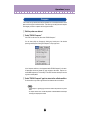
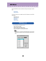
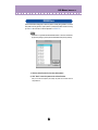
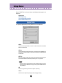
z Select "DX200 Pattern List."
Click "Edit" on the menu bar, then select "DX200 Pattern List."
You can also quickly call up this dialog box by clicking any inactive part of the window pressing control key and clicking "DX200 Pattern List" in the pop-up menu. Or,
you can click "Edit" on the menu bar, then select "DX200 Pattern List."
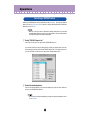
x Select the desired pattern.
Click on the desired pattern, then close the dialog box (click the close button) to
return to the DX200 Editor window.
• You can play the currently selected pattern by clicking on the keys of the keyboard in the DX7
Simulator window.
3
Operations /
Opening the Various Windows
Opening the Various Windows
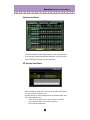
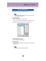
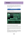
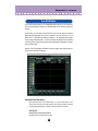
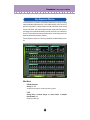
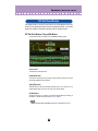
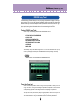
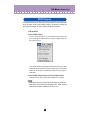
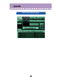
DX200 Editor Main Window
This window provides a comprehensive, at-a-glance display of all DX200 pattern
parameters, and allows you to easily change any desired parameter. (For more
information, see Editing a DX Pattern.)
Alternately, click "Edit" on the menu bar, then select "DX7 Simulator." You can also
call it up from the toolbar.
4
Operations /
Opening the Various Windows
• About the [<= DETAIL] button
Clicking this button lets you toggle between the full editing display (with all parameters
shown) and a smaller editing display (with a limited parameter set). The smaller display
leaves out many of the more detailed parameters, making the editing display less cluttered and easier to handle.
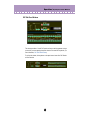
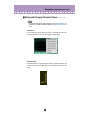
Free EG Window
This window contains the versatile Free EG function, which gives you four tracks for
recording complex real-time parameter changes. To call up the window, click the
"FREE EG" button at the top of the Main window.
5
Operations /
Opening the Various Windows
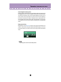
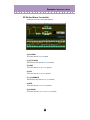
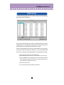
Step Sequencer Window
This window contains the convenient Step Sequencer function, which allows you to
quickly and easily create sophisticated looped Sequences. To call up the window,
click the "STEP SEQ." button at the top of the Main window.
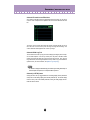
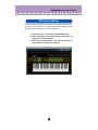
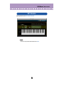
DX7 Simulator Panel Window
Select this window by clicking "Edit" on the menu bar, then selecting "DX7 Simulator." You can also call it up from the toolbar.
No editing functions are directly available from the DX7 Simulator window. However, from this window you can:
• Audition the currently selected pattern by clicking on the keys of the keyboard.
• Open a DX200 File by clicking on the cartridge or cartridge slot.
• Open the Edit Panel windows (below).
6
Operations /
Opening the Various Windows
DX7 Edit Panel Window
This window provides a "virtual" DX7 panel, and lets you edit the patterns much as
you would if you were operating the panel controls of an actual DX7 keyboard. (For
more information, DX7 Edit Panel Window.)
To call up this window, click anywhere on the panel control area of the DX7 Simulator Panel window.
7
Operations /
Opening the Various Windows
Selecting a Mode – Play, Edit or Function
In the Edit Panel window, you can select from among the three main modes: Play, Edit
and Function.
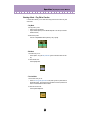
• Play Mode
In the play mode, you can:
• Select one of the 128 patterns.
• Play the selected pattern (from the DX200's keyboard or from the keys in the DX7
Simulator window).
To select the Play mode:
Click one of the [MEMORY SELECT] buttons: [1-32] or [33-64].
• Edit Mode
In the Edit mode, you can:
• Edit the pattern, using the Edit parameters (printed in lavender above each button).
To select the Edit mode:
Click the [EDIT] button.
• Function Mode
In the Function mode, you can:
• Edit the Function (global) parameters of the pattern (printed in yellow below the
appropriate buttons). These include other miscellaneous Function parameters as
well, such as Edit Recall and Pattern Initialize.
To select the Function mode:
Click the [FUNCTION] button.
8
Operations /
Editing a DX200 Pattern
Editing a DX200 Pattern
z Select the desired pattern.
Refer to Selecting a DX200 Pattern.
x Edit the pattern parameters as desired.
c Store the edited settings as a pattern, then save it with other
edited patterns as a DX200 File.
Use the Store operation to store your newly edited pattern. Then use the Save
operation to save that edited pattern with other User Patterns to a DX200 File.
Both the Store and Save operations are necessary to ensure that your pattern is
saved properly. Failing to do so would be roughly similar to writing a letter but not
putting it in an envelope. Make sure to execute both operations when you wish to
keep a pattern you've edited.
9
Operations /
Compare
Compare
This function lets you switch back and forth between the current edited condition of the
pattern and its original un-edited condition. This allows you to easily hear and compare
the changes you make to a pattern with its original condition.
z Edit the pattern as desired.
x Select "DX200 Compare."
Click "Edit" on the menu bar, then select "DX200 Compare."
You can also quickly use Compare by clicking any inactive part of the window
pressing control key and clicking "DX Compare" in the pop-up menu.
In the Compare condition, a check appears beside "DX200 Compare" in the menu.
All parameter values are ghosted (in gray) and cannot be edited. Play the connected MIDI keyboard (or click the keys in the DX7 Simulator window) to hear the
original un-edited pattern.
c Select "DX200 Compare" again to return to the edited condition.
Do this as often as you wish to go back and forth between the two conditions.
• "DX200 Compare" is ghosted (gray) and cannot be selected if the pattern has not yet been
edited.
• The Compare function can be used with the parameter in the Main Window and with Tempo
and Swing in the Step Sequencer window.
10
Operations /
Initializing a DX200 Pattern to the Default Settings
Initializing a DX200 Pattern to the Default Settings
This function allows you to reset all the parameters of the selected pattern to the factory
"initial pattern default values". This gives you a "blank slate" from which you can create
your own pattern.
Keep in mind that this operation automatically erases all the settings of the selected pattern. If you wish to save the pattern for future recall, use the Store and Save functions.
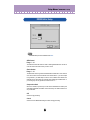
z Select "DX200 Pattern List."
Click "Edit" on the menu bar, then select "DX200 Pattern List."
You can also quickly call up this dialog box by clicking any inactive part of the window pressing control key and clicking "DX200 Pattern List" in the pop-up menu.
x Select the desired pattern to be initialized.
Click on the desired pattern.
c Initialize the pattern.
Click the "Pattern Init." button in the dialog box. The specified pattern is initialized
and automatically selected for editing.
To return to the DX200 Editor window, close the dialog box (click the close button).
11
Operations /
Storing a DX200 Pattern
Storing a DX200 Pattern
This operation lets you store your pattern edits as a User pattern.
• To ensure that your new pattern is available for future recall, make sure to also save the pattern (with other patterns) to a DX200 File.
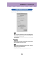
z Select "DX200 Store."
Click "Edit" on the menu bar, then select "DX200 Store."
You can also quickly call up this dialog box by clicking any inactive part of the window pressing control key and clicking "DX200 Store" in the pop-up menu.
x Select the destination pattern.
Click on the desired pattern in the dialog box.
c Store the pattern.
Click the "Store" button in the dialog box. The specified pattern is replaced with the
newly edited pattern.
• This operation deletes the original pattern data at the destination.
12
Operations /
Saving Patterns to a DX200 File
Saving Patterns to a DX200 File
Once you've edited a DX200 pattern to your satisfaction you can save it to a DX200 File.
Each DX200 File can contain up to 64 patterns, and these can be called up at any time
with the Open command. (Also see Calling Up Patterns from a DX200 File.)
Additional DX200 Files of 128 patterns each can be saved to floppy disks or your hard
disk drive as DX200 Files --- giving you unlimited storage for your original patterns. For
organizing the patterns in the DX200 Files, use the convenient DX200 Librarian function.
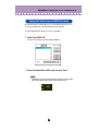
z Select "Save DX200 File."
Click "File" on the menu bar, then select "Save DX200 File."
• "Save DX200 File" can also be selected from the toolbar.
x Select the desired folder, type in the file name, and click "Save."
13
Operations /
Calling Up Patterns from a DX200 File (Open)
Calling Up Patterns from a DX200 File (Open)
Once you've saved a set of User patterns to one or more DX200 Files (see Saving Patterns), you can instantly call up the desired patterns with this command.
To create a new DX200 File, use the New DX200 File command.
z Select "Open DX200 File."
Click "File" on the menu bar, then select "Open DX200 File."
x Select the desired folder and file name, then click "Open."
• "Open DX200 File" can also be selected by clicking on the cartridge slot in the DX7 Simulator
window. (When a DX200 File has been opened, a cartridge is shown in the slot.)
14
Operations /
Receiving Pattern/Voice Data from a DX200/DX7 Series Instrument
Receiving Pattern/Voice Data from a DX200/DX7 Series Instrument
This operation lets you transfer pattern data from an instrument of the DX7 Series. A
single pattern or 128 patterns can be received. (See Receive DX200 Bulk Dump Data).
z Select "Receive DX200 Bulk Dump Data" from the Setup menu.
x Select the desired Receive Method ("1 Voice/Pattern" or "All Patterns/Voices") and Machine (DX200 or DX7 Series).
c Click "Start." The "Start" button changes to "Stop" and the
operation is set to standby (waiting for incoming data).
v Transmit the data from the DX200 or other instrument. (See the
owner's manual of the instrument for instructions.)
• Make sure that the MIDI connections and settings are appropriate. (This includes the "DX200
Editor Setup.")
b As soon as the DX200 Editor starts receiving data, the progress
bar moves, indicating the amount of data received. When the
bar is completely filled, the operation is complete.
To cancel the operation, click "Stop."
n Click "OK" to exit the operation.
15
Parameters
Virtually all of the DX200 Editor parameters for editing the DX200 patterns are contained in the Main control panel window. From this main panel, you can also jump to
other windows for controlling additional DX200 functions (such as the Free EG, Step
Sequencer, and DX7 Simulator).
DX200 Editor Main Window
This is the primary editing window for the DX200 Editor. Virtually all editing functions
and operations are done from this window.
To change any of the parameter values, click on the desired parameter so it is highlighted, then type in the value from the keyboard and press [ENTER].
You can also use the mouse to change the values or settings. Click on the desired
parameter, move the cursor to the top or bottom of the box (to select the "up" arrow or
the "down" arrow, respectively), then click the mouse button to increase or decrease the
value. (Clicking with the "up" arrow increases the value; clicking with the "down" arrow
decreases it.)
Alternately, drag the mouse to continuously change values. Click on the parameter and
drag horizontally or vertically as desired. Dragging to the left or down decreases the
value, and dragging right or up increases it. The parameter value changes accordingly.
Any parameter changes are output as MIDI data, to the DX200.
16
Parameters /
DX200 Editor Main Window
• About the EG combo box and EG window
Also contained in the Main window is a special EG window, from which you can use the
mouse to "draw" envelopes for each Operator's EG, as well as the Pitch EG and Filter
EG.
To use this, click on the down arrow above the window, and select the EG you wish to
edit. Then, click on one of the box "joints" and drag it to change the EG settings. The
current relevant EG values appear at the cursor as you drag it.
• About the DX200 Copy Tool
This convenient function lets you copy the various settings (including EG) from one Operator to another Operator. Click on any inactive part of the panel in the Main window
pressing control key and select "DX Copy Tool" from the pop-up menu. Then, from the
Copy Tool window, click and drag the Operator or EG you want to copy to the destination
Operator or EG. (For more information, see [DX200 Copy Tool] dialog.)
• The Pitch EG is displayed in the DX200 Copy Tool window only for viewing the EG shape. It
cannot be copied to an Operator, nor can an Operator EG be copied to it.
• About the [<= DETAIL] button
Clicking this button lets you toggle between the full editing display (with all parameters
shown) and a smaller editing display (with a limited parameter set). The smaller display
leaves out many of the more detailed parameters, making the editing display less cluttered and easier to handle.
17
Parameters /
DX200 Editor Main Window
• Toolbar
The toolbar gives you quick access to some important functions and controls. These
buttons let you easily execute the desired function without having to select a menu.
Open DX200 Editor File
This is the same as the corresponding command in the File menu. It lets you select and
open an existing DX200 File. (See File Menus, Open DX200 File.)
Save DX200 Editor File
This is the same as the corresponding command in the File menu. It lets you save the
current set of User patterns as a DX200 Editor File for future recall. (See File Menus,
Save DX200 File.)
DX200 Editor Setup
This is the same as the corresponding command in the Setup menu. It lets you make
various important settings for configuring the DX200 Editor with the DX200. (See Setup
Menus, DX200 Editor Setup.)
Transmit DX200 Bulk Dump Data
This is the same as the corresponding command in the Setup menu. It lets you transmit
the current DX200 Editor settings as MIDI data to the DX200. (See Setup Menus, Transmit DX200 Bulk Dump Data.)
Receive DX200 Bulk Dump Data
This is the same as the corresponding command in the Setup menu. It lets you receive
the current DX200 Editor settings as MIDI data from a DX7, DX7II or other DX-compatible instrument. (See Setup Menus, Receive DX200 Bulk Dump Data. Also see Receiving Pattern/Voice Data from a DX200/DX7 Series Instrument)
Open DX7 Simulator
This is the same as the corresponding command in the Edit menu. It lets you open the
DX7 Simulator. (See Edit Menus, Open DX7 Simulator.)
18
Parameters /
DX200 Editor Main Window
■ Setting and Changing Parameter Values ...................
• The conventions described here pertain primarily to the DX200 Editor Main Window. For
information on the controls in the Edit Panel window, see Edit Panel Window / Play and Edit
Modes.
• Combo boxes
For combo boxes (such as the EG select box in Main, or Track Parameter in Free EG),
click the down arrow to expand the box, then highlight the desired setting.
• Parameter sliders
For parameter sliders, click and hold the slider, then drag as desired. Alternately, click
and hold any position along the slider path; the slider automatically snaps to the new
position.
19
Parameters /
DX200 Editor Main Window
• Incrementing/decrementing values
Values and settings in the Main window can be changed by clicking on the value box, and
then dragging the cursor up or down (or right/left), in the direction of the desired change.
To increment or decrement a value, click on the desired parameter, move the cursor to
the top or bottom of the box (to select the "up" arrow or the "down" arrow, respectively),
then click the mouse button to increase or decrease the value. (Clicking with the "up"
arrow increases the value; clicking with the "down" arrow decreases it.) The cursor keys
on the keyboard can be used to move around the parameter grid of the DX200 Editor
window.
• Typing values directly
Most parameters in the Main Window can also be set by typing the value directly in the
value box. Click on the box, then type the desired value and press [enter]. Once a value
box has been selected, you can also use the mouse to change the value (as described
above).
• The [enter] key have no effect in the Pattern Name parameter.
20
Parameters /
DX200 Editor Main Window
■ DX200 Parameters .......................................................
Pattern Name
Settings: 1 ... 0, A ... Z, -, ., space, (ASCII 20H ... 7FH)
This determines the name of the pattern being edited. Up to ten characters can be
entered. (In the DX200 Editor window, both uppercase and lowercase letters can be
entered.)
1) Click on the PATTERN NAME box.
2) At the cursor position, type the desired name. Up to ten characters
(uppercase or lowercase) can be entered.
3) Store the pattern, if desired.
FM Level
Range: 0 ... 127
This determines the level of FM signal.
Noise Parameter
• Noise level
Range: 0 ... 127
This determines the level of the Noise. The higher the value, the greater the Noise Level.
When not using Noise, set the value to "0."
• Noise OSC Type
Settings: White, Pink, UpSlow, UpMid, UpHigh, DownSlow, DownMid,
DownHigh, PitchScale1...4, Variation1...4
This is used to select the type of Noise signal.
For detail of types, refer to the DX200 Editor Owner's Manual.
21
Parameters /
DX200 Editor Main Window
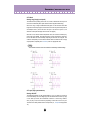
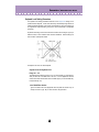
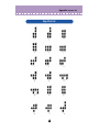
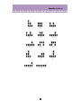
Algorithm
Range: 1 ... 32
This determines the algorithm used for the pattern. The algorithm determines how the
operators are configured for the pattern. The FM synthesis system of the DX200 has 32
of these configurations, called "algorithms." (Refer to the Algorithm List.)
This section displays the signal path, showing which operators are "carriers" and which
are "modulators." The carriers are in the bottom row of the algorithm and are the actual
sound producers for the pattern. Modulators are stacked above the carriers and alter the
timbre or tonal quality of the carriers. A modulator stacked on top of another modulator
alters the timbre even further. Simply put, the carriers produce the sound, and the modulators change the character of the sound.
• Changing the algorithm may result in drastic changes to the pattern, and could produce unexpectedly loud and noisy sounds.
Feedback
Range: 0 ... 7
This determines the level of feedback. Each algorithm provides a feedback operator, in
which the output signal of the operator is looped back to its input. As its name implies,
Feedback produces harsh noise-like harmonics in the pattern. The degree of harshness
or amount of noise depends not only on this setting, but also on the level of the feedback
operator and its position in the algorithm.
Free EG button
Open [Free EG] window.
Step Sequencer button
Open [Step Sequencer] window.
Filter Parameters
The Filter parameters are a special addition to the DX200, not found on the original DXseries synthesizers. The Filter lets you control the tone in various ways, using the same
filter types, functions and parameters as found on analog synthesizers.
The DX200 also features a Filter EG, letting you control the filter operation over time.
(See Filter EG Parameters.)
22
Parameters /
DX200 Editor Main Window
• Filter Type
Determines the filter type used for the VCF section. The filter passes only a specified
range of frequencies while cutting off the rest. There are several completely different
types, as well as a variety of filter slopes (see below).
Settings:
LPF24 (Low Pass Filter 24dB/octave), LPF18 (LPF 18dB/octave), LPF12
(LPF 12dB/octave), BPF (Band Pass Filter), HPF12 (High Pass Filter
12dB/octave), BEF (Band Eliminate Filter)
LPF24, LPF18, LPF12
The Low Pass Filter passes only those frequencies below the specified cutoff point.
Cutoff curves of 24dB/octave, 18dB/octave and 12dB/octave can be selected.
BPF
The Band Pass Filter passes only those frequencies in the specified range, with a cutoff curve of 12dB/octave.
HPF12
The High Pass Filter passes only those frequencies above the specified cutoff point,
with a cutoff curve of 12dB/octave.
23
Parameters /
DX200 Editor Main Window
BEF
The Band Eliminate Filter passes only those frequencies outside the specified frequency range. The Resonance setting (below) determines the eliminate range.
• Filter Cutoff
Range: 0 ... 127
Determines the frequency at which the Filter effect starts. The higher the value, the
higher the frequency.
• Filter Resonance (res)
Range: -16 ... 100
Determines the emphasis of the resonant peak of the Filter (at the Cutoff frequency).
24
Parameters /
DX200 Editor Main Window
• Filter Cutoff Scailing
Range: -64 ... 63
This determines how the Filter Cutoff Frequency follows the keyboard. For a setting of
"0," the particular notes played on the keyboard have no effect on the Filter.
• Filter Input Gain
Range: -12 ... 12 (dB)
Determines the level of the signal sent to the Filter. If the Filter doesn't seem to have
much effect on the sound, try increasing this parameter. If the Filter effect seems too
boomy, loud or harsh, try decreasing this.
Distortion Parameters
Distortion lets you apply a wide variety of distortion and overdrive effects to the
sound, and simulate the effect of various guitar amplifiers and speakers.
• Distortion Switch
Range: On, Off
This turns the Distortion effect on or off.
• Distortion Drive
Range: 0 ... 100
This determines the amount of distortion "drive" for the guitar amplifier simulation effect
block. The higher the value, the greater the degree of distortion in the sound.
• Distortion Dry/Wet
Range: D63>W ... D=W ... D<W63
This determines the level balance of the unprocessed (dry) original sound of the pattern,
and the distortion processed (wet) sound. A setting of D=W results in an equal balance
of dry and wet sound. (In the display, "D" indicates "dry," and "W" indicates "wet.")
• Distortion Guitar Amp. Type
Settings: Off, Stack, Combo, Tube
This determines the type of guitar amplifier simulated by the Distortion effect. Each produces a slightly different distortion sound, recreating the characteristics of an actual
amplifier. "Stack" simulates a separate amp and speaker setup, "Combo" simulates a
single cabinet transistor amp and speaker, and "Tube" simulates a single cabinet tube
amp and speaker. When this is set to "Off," some of the guitar amplifier simulation effect
is cancelled (however, Distortion Drive and LPF are still applied to the sound).
• Distortion Low Pass Filter
Range: 1.0 kHz ... 18.0 kHz, Thru
This determines the frequency of the low pass filter that is applied to the distortion sound.
Depending on the Guitar Amp. Type setting, this parameter can be used to "fatten" the
sound or make it piercing and brittle. When this is set to "Thru," no filtering is applied to
the distortion sound.
• Distortion Output Level
Range: 0 ... 100
This determines the output volume of the distortion sound. Keep in mind that this may
not have any effect unless the Distortion Dry/Wet is set to an appropriate value.
25
Parameters /
DX200 Editor Main Window
Filter EG Parameters
The Filter EG parameters determine how the timbre of the pattern changes over
time. This lets you produce subtle or pronounced filter effects (such as wah, for
example).
You can also conveniently edit the Filter EG parameters from the EG window. To
make changes to this, click on the down arrow above the EG window, and select
the Filter EG. Then, click on one of the box "joints" and drag it to change the EG
settings. The current relevant Filter EG values appear at the cursor as you drag it.
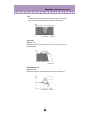
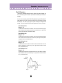
• Filter EG Attack Time
Range: 0 ... 127
This determines the attack time of the Filter EG, which is the time it takes for the signal to
reach its maximum cutoff frequency level after a key is pressed (key on). Higher values
produce a longer Attack time. (See illustration below.)
• Filter EG Decay Time
Range: 0 ... 127
This determines the decay time of the Filter EG, which is the time it takes for the signal to
reach its sustain level from the maximum level while a key is held. Higher values produce
a longer Decay time. (See illustration below.)
• Filter EG Sustain Level
Range: 0 ... 127
This determines the level of sustain of the Filter EG, which is the fixed level of the cutoff
frequency maintained as long as the key is held. Higher values increase the Sustain
level. (See illustration below.)
• Filter EG Release Time
Range: 0 ... 127
This determines the release time of the Filter EG, which is the time it takes for the filter to
reach its initial level after a key is released (key off). Higher values increase the Release
time. (See illustration below.)
26
Parameters /
DX200 Editor Main Window
• Filter EG Depth
Range: -64 ... 0 ... +63
This determines the range of movement of the cutoff frequency. This must be set to a
proper level for the Filter EG parameters (Attack, Decay, Sustain, and Release) to have
an effect on the sound. Positive values increase the Filter EG Depth. Negative values
reverse the shape of the envelope.
• Filter EG Velocity Sense
Range: -64 ... 0 ... +63
This determines how the Filter responds to keyboard velocity. The higher the value (positive), the more sensitive the Filter is to your keyboard playing strength. Negative values
produce the opposite effect; in other words, the Filter effect gets stronger the lighter you
play.
2-Band EQ Parameters
This flexible 2-Band EQ gives you comprehensive control over the sound, with both
Gain and Frequency parameters --- plus a Resonance control on the Mid Frequency band.
• 2-Band EQ Low Gain
Range: -12 ... 0 ... +12 (dB)
This determines the gain or level of the low frequency band. Positive values boost the
level of the frequency and negative values attenuate it.
• 2-Band EQ Low Frequency
Range: 32Hz ... 2.0kHz
This determines the specific frequency that is controlled by the Low Gain parameter
(above).
• 2-Band EQ Mid Gain
Range: -12 ... 0 ... +12 (dB)
This determines the gain or level of the mid frequency band. Positive values boost the
level of the frequency and negative values attenuate it.
• 2-Band EQ Mid Frequency
Range: 100Hz ... 10.0kHz
This determines the specific frequency that is controlled by the Mid Gain parameter
(above).
• 2-Band EQ Mid Resonance
Range: 1.0 ... 12.0
This determines the resonant boost applied to the Mid Frequency.
27
Parameters /
DX200 Editor Main Window
LFO Parameters
The LFO (Low Frequency Oscillator) parameters are used to regularly modulate
the pitch or volume of a pattern, letting you create vibrato, tremolo, or "wah" effects.
These are also related to the Modulation Sensitivity parameters.
• LFO Waveform
Settings:
TRI (triangle)
SAW- (sawtooth down)
SAW+ (sawtooth up)
SQU (square)
SIN (sine)
S/Hold (sample and hold)
This determines the waveform of the LFO: triangle, sawtooth down, sawtooth up, square,
sine, or sample and hold.
• LFO Speed
Range: 0 ... 99
This determines the speed or frequency of the LFO, with higher values resulting in higher
frequencies (greater speed).
28
Parameters /
DX200 Editor Main Window
• LFO PMD (Pitch Modulation Depth)
Range: 0 ... 99
This determines the amount of Pitch Modulation Depth. This sets the degree to which
LFO modulation affects the pitch of the pattern, or how widely pitch is modulated by the
LFO. This produces a vibrato effect for the pattern. This has no effect if Pitch Modulation
Sensitivity is set to zero.
• LFO AMD (Amplitude Modulation Depth)
Range: 0 ... 99
This determines the amount of Amplitude Modulation Depth. This sets the degree to
which LFO modulation affects the volume of the pattern, or how widely volume is modulated by the LFO. When applied to a carrier operator, this produces a tremolo effect;
when applied to a modulator, it produces a "wah" effect. This has no effect if Amplitude
Modulation Sensitivity is set to zero.
• LFO FMD (Filter Modulation Depth)
Range: 0 ... 99
This determines the amount of Filter Modulation Depth. This sets the degree to which
LFO modulation affects the filter of the pattern, or how widely filter is modulated by the
LFO.
• LFO Delay
Range: 0 ... 99
This determines the delay time for the LFO, or the amount of time that elapses between
the press of a key and onset of the LFO effect. This is useful in producing delayed vibrato
or tremolo effects (often used by singers or instrumentalists). Higher values result in a
longer delay time.
• Both Pitch and Amplitude are modulated together by the LFO; LFO cannot be set to modulate
these independently. However, by using the Sensitivity and Depth controls, you can set different degrees of the LFO effect for each.
29
Parameters /
DX200 Editor Main Window
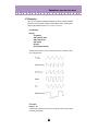
• LFO Mode
Settings: sngl (single), mult (multi)
This determines the operating mode of the LFO; in effect, it determines how many LFOs
are used to modulate the pattern (when several notes are played simultaneously).
When set to "sngl," a single LFO affects all notes played. In other words, the LFO effect
begins when the first key is played, and continues in the same way at the same phase for
all subsequent notes. (This is true when LFO Sync is off; when LFO Sync is on, the
waveform is interrupted and begins anew for each note played.)
When set to "mult," there are sixteen independent LFOs, one for each of the sixteen polyphonic notes of the DX200. This means that when you play several notes in sucession,
the LFO will affect each note individually, depending on when each note is played. This
creates an exceptionally rich and natural modulation effect for sustained notes in strings
and pad patterns, especially when LFO Delay is set to an appropriate value.
• These illustrations show the various LFO conditions for different Sync and Mode settings.
• LFO Sync (Key Synchronization)
Settings: ON, OFF
This determines whether LFO Key Synchronization is on or off. When Sync is ON, the
LFO is automatically reset to the beginning of the selected waveform each time you play
a note. When sync is OFF, the LFO waveform continues in a "free running" condition;
when you play a note, the result will vary depending on where the LFO is in the cycle.
The effect can be easily detected at low LFO frequencies (i.e., LFO Speed settings below
10).
30
Parameters /
DX200 Editor Main Window
Key Transpose
Range: C1 - C5 (MIDI notes 36 - 84)
This determines the overall pitch (key) transposition setting for the pattern. The default
value is C3 (60). Use this control to change the octave setting of a pattern, or change it
to a key for ease in playing. For example, to play the pattern in the key of C but have it
sound in the key of F#, enter a value of F#3 or F#2 (depending on whether you want to
transpose up or down).
In the DX200 Editor window:
Click KEY TRANSPOSE, then type in the value MIDI note value (36 - 84; note names
cannot be typed) and press [enter] on the computer keyboard. Or use the mouse buttons to increment/decrement the values.
In the Edit Panel window:
1) Click on Pattern Select button [31] (KEY TRANSPOSE).
2) Select the DX200 Editor window.
3) Click the desired key on the "virtual" keyboard. (The DATA ENTRY controls in the
Edit Panel window cannot be used to change the value.)
4) Return to the Edit Panel window to continue editing or save the pattern.
Pitch Bend Parameters
These parameters determine how the Pitch Bend wheel (on the connected MIDI
keyboard) affects the pitch of the pattern.
• The Pitch Bend parameters are Function mode parameters in the Edit Panel window.
• Pitch Bend Range
Range: 0 ... 12 semitones
This determines the maximum amount of pitch change with the Pitch Bend wheel, up or
down. When set to "0," there is no pitch change. When set to the default of "2," pitch can
be raised or lowered by a maximum of 2 semitones (1 whole step). The maximum setting
of "12" gives you a full two-octave range (one octave down, one up).
• This parameter is automatically set to "12" and cannot be changed unless Pitch Bend Step
(below) is set to "0."
31
Parameters /
DX200 Editor Main Window
• Pitch Bend Step
Range: 0 ... 12 (semitones)
This determines the size of the increments by which the Pitch Bend wheel (on a connected MIDI keyboard) changes the pitch. A setting of "0" results in perfectly smooth
pitch bending. Values other than "0" represent the number of semitones by which the
pitch will "jump" as you move the wheel. For example, the maximum setting of "12" will
cause the wheel to change the pitch in a single, one-octave jump.
• When this parameter is set to a value other than "0," Pitch Bend Range (above) is automatically set to "12." (In order to change Pitch Bend Range, this parameter must be set to "0.")
Portamento
These three parameters are used to set portamento (glide) and glissando (stepped
glide) effects, and to control certain sustain characteristics of the keyboard. The
particular effects available will change, depending on the Poly/Mono setting of the
pattern.
•The Portamento parameters are Function mode parameters in the Edit Panel window.
• Step
Settings: 0 ... 12 (semitones)
When Glissando is set to 1...12, the glide in pitch occurs in discrete semitone steps. This
effect is best heard with a slower rate and when two widely separated notes are played
one after the other. When Glissando is set to "OFF," normal (continuous) Portamento is
available.
• Time
Range: 0 ... 99
This determines the time of the Portamento or Glissando effects. A setting of "0" produces no effect, while a setting of "99" produces the longest (slowest) pitch changes.
This is contrary to the operation of most DX200 rate controls for which higher values
result in faster (shorter) times. In order to turn Portamento or Glissando off, make sure to
set this to "0."
• Mode
Settings:
In Mono mode:
Fingered Porta
Full Time Porta
In Poly mode:
Sus-Key P Follow
Sus-Key P Retain
32
Parameters /
DX200 Editor Main Window
When the keyboard is in Mono mode, the available settings are "Fingered Porta" and
"Full Time Porta." Fingered Portamento is glide that occurs only when you play legato --in other words, playing successive notes smoothly, not releasing a previously played note
until after the next note is played. Full Time Portamento produces glide from one note to
the next even when you play staccato (releasing one note before playing the next).
When the keyboard is in Poly mode, the available settings are "Sus-Key P Follow" and
"Sus-Key P Retain." In Sustain-Key Pitch Follow mode, if you play a note or chord and
then play another note or chord, the sustain from the original note/chord glides to the
pitch of the most recently played note/chord. In Sustain-Key Pitch Retain mode, the pitch
of the new note or chord glides from that original pitch(es) without interrupting the sustain
of the original note or chord.
Unison Parameters
These parameters let you "fatten" up sound of a pattern, by grouping together four
detuned "copies" of the pattern for every note played.
The DX200 features sixteen-note polyphony, meaning that sixteen notes can be
played simultaneously. In effect, a pattern is made up of sixteen sound generating
"elements," one for each note of polyphony.
The Unison parameters let you reconfigure the element assignment of the DX200
such that four elements sound together in unison when you play a single note. The
elements can be detuned from each other by a variable amount, adding warmth
and richness to the sound of the pattern.
• The overall polyphony of the DX200 is reduced when Unison is on. Normally, polyphony is
sixteen; when Unison is on, it is four. (Naturally, when Poly/Mono is set to "Mono," polyphony
is fixed at one, no matter what the Unison setting is.)
• These parameters are not available in the Edit Panel window.
• Unison Switch
Settings: ON, OFF
This determines whether the Unison function is on or not. When set to "ON," four of the
DX200's sixteen sound generating "elements" are sounded in unison for each note
played. Keep in mind that this reduces the overall polyphony of the instrument.
• Unison Detune
Range: 0 ... 7
This determines the amount of detuning applied for the Unison function. This setting has
no effect unless Unison Switch is set to "ON." A value of "0" results in no detuning;
higher values shift the tuning of the four sound generating "elements" further away from
each other, creating a warm, fat sound.
33
Parameters /
DX200 Editor Main Window
Poly/Mono
Settings: Poly, Mono
This determines how notes of the pattern are allocated. The "Mono" (monophonic) setting allows only one note to be sounded at a time. This is useful for reproducing "classic"
synthesizer lead and bass sounds, and is also ideal for playing parts in which you deliberately want the end of one note to be cut off by the next. The "Poly" setting allows you to
play up to sixteen notes simultaneously.
• Poly/Mono is a Function mode parameter in the Edit Panel window.
Random Pitch
Range: 0 ... 7
This function lets you randomize the overall pitch of the pattern for each note you play.
When this is set to "0," Random Pitch is turned off. Higher values produce greater
amounts of random pitch change for successively played notes.
Pitch Envelope Generator (Pitch EG) Parameters
These parameters (eleven altogether) determine how the pitch of the pattern
changes over time. The Pitch EG parameters affect all operators equally.
The four Level parameters determine the pitch of the operator at five different
points, and the four Rate parameters determine the amount of time that elapses
between changes of pitch. Range, Rate Scaling, and Velocity Switch parameters
give you further detailed control over the Pitch EG effect.
Pitch EG can be used to reproduce the subtle pitch changes of acoustic instruments (for example, at the beginning and/or end of a note). At extreme settings, it
also can be used to create unusual special effects.
You can also conveniently edit the Pitch EG parameters from the EG window. To
make changes to this, click on the down arrow above the EG window, and select
the Pitch EG. Then, click on one of the box "joints" and drag it to change the EG
settings. The current relevant Pitch EG values appear at the cursor as you drag it.
• A real-time pitch controller, such as the Pitch Bend wheel on a connected MIDI keyboard, can be
used to augment (or cancel) the "automatic" pitch changes made in the Pitch EG parameters.
34
Parameters /
DX200 Editor Main Window
• Pitch EG Rate 1 - 4
Range: 0 ... 99
These determine the amount of time that elapses between changes in the pitch (as set in
Level 1 - 4 below).
• Pitch EG Level 1 - 4
Range: 0 ... 99
These determine the overall pitch of the pattern at five points in time. A value of "50" corresponds to normal pitch, or no pitch change. Values under "50" lower the pitch, and values above "50" raise it. The actual pitch range here depends on the Pitch EG Range
parameter setting. (Higher Pitch EG Range settings result in greater pitch variation.)
The amount of time that elapses between these pitch change points is set in Rate 1 - 4
above.
In the Edit Panel window:
Click button [29] (PITCH EG RATE) repeatedly to call up Rate 1, 2, 3, and 4 in succession. (This includes the Pitch EG Rate Scaling parameter.) Likewise, click button
[30] (PITCH EG LEVEL) repeatedly to call up Level 1, 2, 3, and 4 in succession.
(This includes the Pitch EG Level Range parameter.) Use the DATA ENTRY controls
to set the value for each parameter.
• Pitch EG Range
Settings:
1/2v (six semitones)
1va (one octave)
2va (two octaves)
8va (eight octaves)
This determines the maximum range of pitch change with the Pitch EG. For example,
when this is set to "1va," the full range of the Pitch EG Level 1 - 4 parameters is one
octave (six semitones above and below the normal pitch value of "50"). The minimum
setting of "1/2v" lets you create subtle pitch changes, whereas the maximum setting of
"8va" is for extreme pitch variations.
35
Parameters /
DX200 Editor Main Window
• Pitch EG Rate Scaling
Range: 0 ... 7
This determines how the Rate times of the Pitch EG respond to keyboard position. In
other words, this lets you automatically speed up or slow down the overall Pitch EG time
(Rate 1 - 4) of the pattern depending on which range of the keyboard you play. This
parameter controls the degree of scaling; a value of "0" produces no scaling, and higher
values produce a more pronounced scaling effect. For values other than "0," the higher
the note played, the shorter its overall Pitch EG time.
Pitch EG Rate Scaling is useful for simulating the natural pitch scaling found on many
acoustic instruments --- for example, as on a cello or double bass, for which the beginnings of lower notes may have a slower rise in pitch. It's also useful for producing
unusual pitch change effects depending on key position.
• Pitch EG Velocity Switch
Settings: ON, OFF
This determines whether Pitch EG intensity is touch sensitive or not. When set to "ON,"
the range of pitch change of the Pitch EG is affected by key velocity. This gives you
exceptionally realistic and expressive control over Pitch EG changes.
Oscillator Parameters
The Oscillator parameters give you detailed control over the pitch or frequency of the individual operators of a pattern.
• Oscillator Mode
Settings: Ratio, Fixed
This determines whether each operator changes pitch according to the notes playes.
When set to "Ratio" (Frequency Ratio Mode), the corresponding operator tracks the keyboard pitch normally. In other words, playing higher notes on the keyboard results in correspondingly higher frequencies on the operator. When set to "Fixed" (Fixed Pitch
Mode), the keyboard does not affect the operator's frequency; the operator plays at the
same pitch no matter what key is played.
• The term "oscillator" refers to the frequency or waveform generating element of the operator.
36
Parameters /
DX200 Editor Main Window
• Oscillator Sync (Key Synchronization)
Settings: ON, OFF
This determines whether Oscillator Key Synchronization is on or off --- whether or not the
waveforms of all operators start at the beginning of the wave cycle when a key is
pressed. Note that this affects all operators together.
When Sync is ON, the oscillators are automatically reset to the beginning of their waveforms each time you play a note. When sync is OFF, the waveforms continues in a "free
running" condition; when you play a note, the result will vary depending on where the
waveform is in the cycle. This creates subtle differences in the sound, even when you
play the same note repeatedly. Keep in mind that for certain patterns, there may be little
or no audible effect.
Frequency Coarse/Fine
Range (in Ratio mode): 0.500 ... 61.69
Range (in Fixed mode): 1.000 Hz ... 9772 Hz
This determines the frequency for each individual operator.
Type in the desired value in the appropriate value box or use the mouse to change the
value.
Detune
Range: -7 ... +7
Detune is a "super fine" frequency adjustment for each operator. Mild detuning between
carrier operators can make the overall sound of the pattern more full, rich and natural,
and reproduce the subtle pitch differences found in actual acoustic instruments. Maximum detuning between carriers can be used to produce chorusing effects or simulate an
ensemble of multiple instruments.
Operator Parameters
These parameters let you set the Output Level and Velocity Sensitivity for each operator.
• Operator Output Level
Range: 0 ... 99
This determines the level of each operator. The setting made here affects the workings
of many other parameters. For example, Feedback, EG Level 1 - 4, and Velocity Sensitivity may have little or no audible effect if Output Level is set too low. On the other hand,
Keyboard Level Scaling settings may have little or no effect if Output Level is set too high.
When applied to a carrier operator, this affects the volume of the pattern; when applied to
a modulator, it affects the timbre.
37
Parameters /
DX200 Editor Main Window
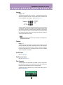
About Operator On/Off Controls
Each operator can be independently turned on and off during editing --- an important
tool in hearing the effects of your edits. For example, you may want to temporarily
mute one carrier operator to better hear the edits you are making on another carrier.
Or you may want to turn an operator alternately on and off to hear how its presence
and absence affects the overall sound.
The numbers in the top row indicate the operators' on/off status:
"1" for on, "0" for off. In this example, operator 3 is off.
Click the appropriate "OP No." (Operator Number) button (1 - 6). When an operator is
off, all its parameters are ghosted.
Keep in mind that Operator On/Off is used only temporarily in editing and the on/off status is not saved with the pattern. To actually turn an operator off, set its Output Level to
"0."
• Operator Key Velocity Sensitivity
Range: 0 ... 7
This determines the touch sensitivity of an operator, or how its level responds to your
playing strength. When Velocity Sensitivity is set to a value other than "0," the harder you
play a key, the greater the level of the corresponding operator. The softer you play a key,
the lower the level. When this is set to "0," the operator level remains the same, no matter how softly or strongly you play the key. Higher values give you greater dynamic range
between low and high levels. Setting this to an appropriate value for a carrier operator
gives you touch control over volume; setting it for a modulator gives you touch control
over timbre.
38
Parameters /
DX200 Editor Main Window
Envelope Generator (EG) Parameters
These parameters (eight for each operator) determine how the level of the operator changes
over time. EG applied to a carrier operator changes the volume of the sound over time, while
EG applied to a modulator changes the timbre or the tonal characteristics.
The four Level parameters determine the levels of the operator at five different points, and
the four Rate parameters determine the amount of time that elapses between changes of
levels. Together, these eight settings give you detailed control over the shape (attack, decay,
sustain and release) of the sound, both in volume and timbre.
You can also conveniently edit the Operator EG parameters from the EG window. To make
changes to this, click on the down arrow above the EG window, and select the desired Operator's EG (1 - 6). Then, click on one of the box "joints" and drag it to change the EG settings.
The current relevant EG values appear at the cursor as you drag it.
The EG Copy function (in the Edit Panel window) and DX Copy Tool (in the DX200 Editor
window) let you easily copy all EG Rate and Level values of one operator to another operator.
• Rate 1 - 4
Range: 0 ... 99
These determine the amount of time that elapses between changes in the operator level
(as set in Level 1 - 4 below).
• Level 1 - 4
Range: 0 ... 99
These determine the levels of the operator at five points in time. The amount of time that
elapses between these points is set in Rate 1 - 4 above.
• For most normal applications --- and especially for carrier operators --- the Level 4 parameter
(which determines both the starting and ending level of the operator) should be set to "0."
Otherwise, the pattern will continue to sound indefinitely. Also, Level 1 should be set to an
appropriate value, such as "50" or greater, for proper EG operation.
Type in the desired value in the appropriate value box or use the mouse to change the
value.
39
Parameters /
DX200 Editor Main Window
Modulation Sensitivity Parameters
The Modulation Sensitivity parameters (Pitch and Amplitude) determine the degree to which
LFO modulation affects the pattern --- in other words, the intensity of the LFO effect. Modulation Sensitivity is effectively a master control for all modulation --- whether it is automatically applied when the notes are played, or whether it is applied only by using the "real time"
modulation controls on the MIDI keyboard, such as the Modulation Wheel, Foot Control,
Breath Control or After Touch. If the Pitch or Amplitude Modulation sensitivity is set at zero,
then none of the external controllers can affect the patterns.
• Pitch Modulation Sensitivity
Range: 0 ... 7
This determines sensitivity of the pattern (all operators) to LFO pitch modulation. Higher
values result in greater sensitivity, or greater intensity of pitch modulation. This parameter setting affects all operators of the pattern equally.
• Amplitude Modulation Sensitivity
Range: 0 ... 7
This determines sensitivity of each operator to LFO amplitude (volume) modulation.
Higher values result in greater sensitivity, or greater intensity of volume modulation.
When applied to carrier operators, this produces a tremolo effect. When applied to a
modulator operator, this varies the timbre, producing a "wah" effect.
• These settings may have little or no effect on the sound if the Operator Level is set to a low
value.
40
Parameters /
DX200 Editor Main Window
Keyboard Level Scaling Parameters
The Keyboard Level Scaling parameters determine how the Output Level settings of the
operators track the keyboard. In other words, these let you automatically change the level of
individual operators depending on which range of the keyboard you play. Each operator can
be programmed to respond according to any of four curves on either side of an adjustable
break point.
Keyboard Level Scaling can be used to make the tone and/or volume change as you play in
different octaves, for more realistic acoustic instrument simulations. Extreme settings can
also be used for "split keyboard" effects.
The Depth of each curve can also be adjusted.
• Keyboard Level Scaling Break Point
Range: A-1 ... C8
This determines the middle point for the curve. The level is scaled up or down independently on either side of the Break Point in the curve. For most applications and best
results, this should be set somewhere near the middle range of your connected MIDI keyboard (for example, C3).
In the DX200 Editor window:
Type in the desired value in the appropriate value box (MIDI note numbers only; for
example, to select C3, type "60") or use the mouse to change the value.
41
Parameters /
DX200 Editor Main Window
• Keyboard Level Scaling Curve Left (L), Curve Right (R)
Settings:
-LIN (Linear, negative)
-EXP (Exponential, negative)
EXP (Exponential, positive)
LIN (Linear, positive)
These parameters determine the left and right Keyboard Scaling Curves for each of the
operators. Curve Left corresponds to the keys on the keyboard lower than the Break
Point, and Curve Right corresponds to the keys higher than the Break Point. Any one of
the Left Curves can be used with any one of the Right Curves, giving you sixteen different curve variations to choose from.
Negative curves decrease the operator level as you play notes further away from the
Break Point, and positive curves increase the level.
Exponential curves feature a more gradual change in level near the Break Point, and
change the level more drastically the further you play away from the Break Point. Linear
curves provide a "straight line," proportional relationship between the note played and the
resulting operator level.
• Keyboard Level Scaling Depth Left (L), Depth Right (R)
Range: 0 ... 99
These parameters determine the depth of the selected left or right curve. At a minimum
setting ("0"), there is no scaling, and you can increase (or decrease, for negative curves)
the level up to maximum of "99."
• For values near the maximum, there has to be some "headroom" --- in other words, some
operator output level must be available for increasing. For example, if the Operator Output
Level is set to "90," and a positive (+) curve is set, the greatest curve depth that can be
achieved is "9" (the difference between the maximum Output Level and the actual set value).
In this example, while the curve Depth can be set to a value greater than 9, there will be no
more effect than if it were set at 9; if you want more boost as you move up or down the keyboard, then you'll have to set the operator Output Level at a lower value so that more "headroom" is available for the scaling to boost the level to the maximum of 99.
42
Parameters /
DX200 Editor Main Window
• Keyboard Rate Scaling
Range: 0 ... 7
This determines how the Rate times of the EG respond to keyboard position. In other
words, this lets you automatically speed up or slow down the overall EG time (Rate 1 - 4)
of individual operators depending on which range of the keyboard you play. This parameter controls the degree of scaling; a value of "0" produces no scaling, and higher values
produce a more pronounced scaling effect. For values other than "0," the higher the note
played, the shorter its overall EG time.
Keyboard Rate Scaling is useful for simulating the natural scaling found on many acoustic instruments --- for example, as on an acoustic piano, on which higher notes decay
more quickly than lower notes.
43
Parameters /
DX200 Editor Main Window
EG Copy
This convenient function (in the Edit Panel window) allows you to easily copy all EG Rate and
Level values of one operator to another operator. (In the DX200 Editor window, use DX200
Copy Tool.)
z Select the source operator, by repeatedly clicking the [OPERATOR
SELECT] button.
The currently selected operator number is shown at the top right of the LCD.
x Click the [STORE] button.
c Click the desired [EG COPY] button (1 - 6), corresponding to the number of the destination operator.
The source operator values are automatically copied to the destination operator.
(The LCD shows the source operator values.)
44
Parameters /
Free EG Window
Free EG Window
The Free EG function gives you four independent tracks to which you can record complex real-time parameter changes, over a specified length of time, either in measures or
seconds.
In this window, you can draw a custom Free EG "curve" for each track that controls a
single selectable parameter (such as filter, resonance, LFO, etc.) over time. Four of
these curves --- each affecting a different parameter --- can be played back automatically by simply playing the pattern. A variety of drawing and editing tools are available
for creating unique, continuous parameter changes that would be impossible to achieve
with conventional EGs.
Naturally, Free EG parameters and data are stored as pattern data, allowing each pattern to have its own Free EG settings.
Individual Track Parameters
These parameters apply to each individual track (1 - 4) of the Free EG function. Each
track can have its own EG "curve" and parameter. When a pattern is played, all Free EG
tracks playback simultaneously, controlling the assigned parameters in real time.
• EDIT SELECT
Settings: Track 1, Track 2, Track 3, Track 4
This determines the particular track for editing.
45
Parameters /
Free EG Window
• TRACK PARAMETER Switch
Settings: ON, OFF
This determines whether the specified track is active (ON) or not (OFF). This must be set
to "ON" for the Free EG of the track to have any effect.
When this is set to "ON," two red dotted lines appear in the Free EG display. These represent the range over which the selected parameter (set in Track Parameter below) can be
changed by the Free EG curve. The position of these two lines depends on the particular
parameter and its current value or setting. A Free EG curve can extend above or below
these lines; however, the portions that extend will have no further effect on the parameter
(beyond the values represented by the lines).
• TRACK PARAMETER
This determines which DX200 parameter will be played by the EG "curve" in the selected
Free EG track. Only one parameter can be selected for a track.
• VALUE Display
This shows the current value or setting for the selected Track Parameter. Keep in mind
that this is only a display indication; the value/setting cannot be changed here, but must
be changed from the appropriate parameter in the main control panel window (or the
Details page).
• TRACK Display Buttons 1 - 4
Click on each of these to display the Free EG curves of two or more tracks simultaneously. Each track's curve is shown in a different color, making it easy to distinguish
between the tracks.
TRACK COMMON PARAMETERS
• LENGTH
Settings:
1/2, 1, 3/2, 2, 3, 4, 6, 8 bars (number of measures)
1.0 ... 16.0 sec (seconds)
The Length setting determines the time for recording and play of the Free EG sequence.
There are two Length types, including length determined by number of measures (bars)
or by absolute time (seconds).
• Setting the Length to a number of bars automatically causes the Free EG to be affected by
Tempo.
• TRIGGER
Settings : Free, MIDI In Notes, All Notes, Seq Start
This determines how the Free EG track playback is triggered, as described below.
Free
After selecting a pattern, the first key pressed on the keyboard triggers the Free EG.
46
Parameters /
Free EG Window
MIDI in Notes
The Free EG is triggered by a note on message from a connected MIDI instrument or
sequencer.
All Notes
The Free EG is triggered by either a Note On message from a connected MIDI instrument or sequencer, or from the first recorded Step of the Step Sequencer.
Seq Start
The Free EG is triggered by the start of the Step Sequencer.
• LOOP TYPE
Settings: Off, Forward, Forward Half, Alternate, Alternate Half
This determines the type of loop for play of the Free EG sequence, as described below.
Off
The Free EG sequence plays once but does not loop. The parameter settings at the
end of the Free EG sequence remain in effect.
Forward
The Free EG sequence loops from start to end.
Forward Half
The Free EG sequence loops from the middle to the end.
Alternate
The Free EG sequence loops from start to end, then end to start.
Alternate Half
The Free EG sequence loops from middle to end, then end to middle.
• TEMPO
Range: 20 - 300 bpm (beats per minute)
This determines the tempo or speed at which the selected Free EG track plays back.
• The Tempo setting also affects the Step Sequencer patterns.
47
Parameters /
Free EG Window
Edit Tools
Indicates the starting point
of the selected range.
Indicates the select point
(along the X-axis, expressed in steps).
Indicates the ending point
of the selected range.
Indicates the value (height of the curve
along the Y-axis) at the selected point.
The toolbar at the left of the Free EG window contains the Edit tools. They are divided
into two basic types: the Drawing tools (which include special wave tools) and the Transform tools.
Using the Drawing Tools
1) Click on the desired Drawing tool.
For details on each tool, refer to the descriptions in step #2 below.
2) Hold down the mouse button at the desired start point, and simultaneously drag the mouse to draw the curve. Release the button to
stop drawing.
For the pencil tool, the curve is immediately changed. For the other tools, a "ghost"
curve temporarily appears (along with the original one) while you are drawing to
indicate the new curve. Release the mouse button, and after a slight pause, the
newly drawn curve replaces the old one. However, for any area left undrawn, the
original curve remains.
pencil
The "pencil" tool lets you draw the desired curve in freehand.
straight
The "straight" tool lets you draw a perfectly straight line by "pulling" the cursor away
from the starting point.
48
Parameters /
Free EG Window
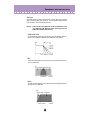
pulse
triangle
sine
These three wave tools let you easily draw the respective waveforms. The example
illustrations below (using the sine wave) show how dragging the mouse affects the
wave.
• Dragging the mouse up or down increases the amplitude of the wave, or the
degree to which the parameter value will change.
• Dragging up creates a waveform of normal phase.
• Dragging down reverses the phase by 180 degrees.
• Dragging to the right decreases the frequency, or makes the parameter value
change slower, while dragging to the left increases the frequency.
49
Parameters /
Free EG Window
Using the Transform Tools
1) Click on the "cursor" button.
2) Highlight (define) the area you wish to transform.
Move the cursor to the beginning point of the desired area, then hold down the
mouse button and drag the mouse to the right, highlighting or defining the area to be
changed. Release the button to set the highlight end point.
• The Transform tools are "ghosted" unless an area is defined.
3) Click on the desired Transform tool.
For the "smooth" and "random" tools, clicking on the respective button starts the
operation. After a short pause, the Free EG curve changes according to the transform.
smooth
As its name suggests, this transform "smooths" jagged edges in the curve. Use
this repeatedly to make the edges as round as desired.
random
This transform randomly assigns different values at successive points in the curve.
To a certain extent, this is the opposite of "smooth" above, since it produces jagged
jumps and edges in the curve.
4) If using "scale" or "move," use the mouse to adjust the setting as
desired.
For the "scale" and "move" tools, hold down the mouse button and drag the mouse
in the appropriate direction, releasing it at the desired point.
scale
This useful tool lets you compress or expand the overall "dynamic range" of the
curve. For example, if the changes in the Free EG are too sudden or dramatic, use
this to compress the curve and make the changes more subtle. Dragging away
from the central axis expands the range; dragging toward the axis compresses it.
Dragging up maintains the original phase; dragging it down reverses the phase by
180 degrees.
move
This is a combination copy-and-paste operation, allowing you to "grab" a defined
section of the curve and move it to another place. The copied section can be
moved freely in any direction, and it replaces the original curve at the destination.
50
Parameters /
Step Sequencer Window
Step Sequencer Window
The Step Sequencer is a powerful, versatile feature that allows you to quickly and easily
create sophisticated looped Sequences. It's also highly interactive, since it can be triggered from the keyboard in a variety of ways, and can be used with the various real-time
controls of the DX200. Each individual step event (Note, Velocity, Gate Time, and Control Change) can be accessed and edited by a specific "panel knob," over a maximum of
16 steps. The Step Sequencer features extensive memory as well, letting you save one
Sequence pattern with each pattern (128 total).
The Step Sequencer share a set of "Common" parameters for added flexibility and control.
Effect Block
• PARAM (Parameter)
Settings: 0 ... 127
This determines the degree for the effect selected in Type below.
• TYPE
Settings: Delay 1-3, Reverb, Flanger 1-2, Chorus, Phaser 1-3, AmpSim
(Amp Simulator) 1-3
Determines the Effect type.
51
Parameters /
Step Sequencer Window
COMMON Block
• TEMPO
Settings: 20 ... 300 bpm (beats per minute)
The Tempo setting determines the tempo for the DX200's internal clock in beats per
minute (BPM), between a range of 40 and 240 BPM. The Tempo setting controls Step
Sequencer playback.
• When Tempo is set to "MIDI," the DX200's clock can be controlled by the clock of an external
MIDI device such as a music sequencer, connected to the MIDI [IN] terminal.
• When the Free EG Length parameter is set to one of the "bar" values, the Free EG sequence
will be synchronized with the Tempo set here.
• BEAT
Settings: 8, 12, 16
Determines the number of steps in the selected Sequence for playback.
• SWING
Settings: 50 ... 83%
The Swing parameter lets you apply a Swing rate to the Sequence to slightly shift certain
beats in order to create a "swing" feel. A setting of "50%" produces no Swing and "83%"
produces maximum Swing. For information about how the Swing levels affect the rhythm
of the Sequence, see the illustration below.
• REVERSE
Setting: On, Off
This function lets you completely turn the Sequence around, and play all the notes backwards.
• GATE TM (Gate Time)
Settings: 1 ... 200%
This is an offset contol and determines the note length of the notes of the Sequence, making all notes either shorter or longer, as a percentage of the original. This lets you, for
example, set the note to play staccato, so that its sound switches off well before its step
time is over. Or you can have the note hold right up to the start of the subsequent step so
that it slurs (legato) into the next note. A setting of "100%" maintains the original relationship between notes. Lower values decrease the Gate Time, and higher values increase it.
• When the combined value of any individual note's Gate Time (as set from the Gate Time Bank
knobs) and the offset Gate Time (set here) exceeds 100%, the note is played legato.
52
Parameters /
Step Sequencer Window
TRACK PARAMETER block
• CUTOFF (Cutoff Frequency)
Settings: Synth track 0 ... 127
Rhythm 1 ... 3 track -64 ... 63
Determines the frequency at which the Filter effect starts of each track. The higher the
value, the higher the frequency.
• RES (Resonance)
Settings: Synth track -16 ... 100
Rhythm 1 ... 3 track -64 ... 63
Determines the emphasis of the resonant peak of the Filter (at the Cutoff frequency) of
each track.
• VOLUME
Settings: 0 ... 127
Controls the volume level of each track.
• PAN
Settings: Synth track C, L63 ... C ... R63
Rhythm 1 ... 3 track RND (Random), L63 ... C ... R63
Determines the panning position (the left or right placement in the stereo image) spectrum of each track. The Random setting (available only for Rhythm tracks) automatically
and randomly specifies a Pan position for each instrument sound.
• WET
Settings: 0 ... 127
Changes the depth or degree of the Effect of each track. When set to the 0 (all the way
left), the Effect sound cannot be heard.
PLAY/STOP buttons
Click the [PLAY] button to start the Sequence. The Sequence repeats (loops) until you
click the [STOP] button to stop it.
NOTE NO./INST.SELECT/VELOCITY/GATE TIME/PITCH
The Step Sequencer allows you to enter notes and other parameter settings to a
Sequence one-by-one.
• NOTE NO. (Note Number) Bank (Synth track only)
Range: C-2 ... G8 (MIDI note numbers 0 ... 127)
This bank of 16 virtual "knobs" lets you set the note number for each step of the
Sequence. To set the note, adjust the parameter normally by "turning" the appropriate
knob, or click on the value window above the knob to call up the pop-up value list, and
click the desired note number.
53
Parameters /
Step Sequencer Window
• INST. SELECT Bank (Rhythm tracks only)
Settings: Refer to "Inst List" of the DX200 Owner's Manual.
This bank of 16 virtual "knobs" lets you select the instrument sound (drums, percussion,
bass, sound effects) for each step of the Sequence. To set the instrument, adjust the
parameter normally by "turning" the appropriate knob, or click on the instrument window
above the knob to call up the pop-up list, and click the desired instrument.
• VELOCITY Bank
Range: Rest, 1 ... 127
This bank of 16 virtual "knobs" lets you set the note velocity for each step of the Step
Sequencer pattern. To set the velocity, you can use one of these methods:
• Adjust the parameter normally by "turning" the appropriate knob.
• Move the cursor to the value window above the knob and click in the top half of the
window to step up through the values, or click in the bottom half to step down. You
can also continuously fast-forward/-reverse through the values by clicking and dragging --- either up/down, or right/left.
• Use [shift] and the cursor keys to step or fast-forward/-reverse through the values.
• Enter the value directly from the computer keyboard.
When set to "Rest," a rest (no sound) is inserted for the step.
• GATE TIME Bank
Range: 1 ... 1600%
This bank of 16 virtual "knobs" lets you set the gate time (or note length) for each step of
the Step Sequencer pattern. To set the gate time, you can use one of these methods:
• Adjust the parameter normally by "turning" the appropriate knob.
• Move the cursor to the value window above the knob and click in the top half of the
window to step up through the values, or click in the bottom half to step down. You
can also continuously fast-forward/-reverse through the values by clicking and dragging --- either up/down, or right/left.
• Use [shift] and the cursor keys to step or fast-forward/-reverse through the values.
• Enter the value directly from the computer keyboard.
Keep in mind that the final gate time of all the notes in the pattern is also determined by
the Common Gate Time control.
• PITCH Bank (Rhythm tracks only)
Range: -64 ... +24
This bank of 16 virtual "knobs" lets you set the pitch for each step of the Step Sequencer
pattern.
To set the pitch, you can use one of these methods:
• Adjust the parameter normally by "turning" the appropriate knob.
• Move the cursor to the value window above the knob and click in the top half of the
window to step up through the values, or click in the bottom half to step down. You
can also continuously fast-forward/-reverse through the values by clicking and dragging --- either up/down, or right/left.
• Use [shift] and the cursor keys to step or fast-forward/-reverse through the values.
• Enter the value directly from the computer keyboard.
• Step Mute buttons
These determine whether the individual step of the track is on (sounded) or off (muted).
54
Parameters /
DX7 Simulator Window
DX7 Simulator Window
Select this window by clicking "Edit" on the menu bar, then selecting "DX7 Simulator ."
You can also call it up from the toolbar. Keep in mind that you can't directly do any editing from this window. However, you can do three things here:
1) Play the virtual keys --- and hear the connected DX200 sounds.
2) Open a new Pattern, or store a Pattern that you've been editing --- by
clicking on the virtual cartridge slot.
3) Click on the virtual panel controls --- and call up the Edit Panel window, for editing in the fashion of an actual DX7.
55
Parameters /
DX7 Edit Panel Window
DX7 Edit Panel Window
This window provides a "virtual" DX7 panel, and lets you edit the patterns much as you
would if you were operating the panel controls of an actual DX7 keyboard. To call up this
window, click anywhere on the panel control area of the DX7 Simulator window.
DX7 Edit Panel Window / Play and Edit Modes
To select the Play mode, click either one of the [MEMORY SELECT] buttons.
• Volume slider
This adjusts the overall output level.
• DATA ENTRY slider
This is used for making rapid or large changes. Moving it all the way down and up covers
the full range available for each parameter.
• [NO]/[YES] buttons
These are used to increment or decrement parameter values, to turn a function on or off,
answer display prompts, and to move the cursor when naming a pattern.
• [STORE] button
This button calls up the Store operation, for storing the selected pattern to the memory of
the DX200. In the Edit mode, this selects the EG Copy function.
• After you've stored a pattern to the DX200, make sure to save the pattern to a DX200 File.
56
Parameters /
DX7 Edit Panel Window
• [MEMORY PROTECT 1-32/65-96]/[MEMORY PROTECT 33-64/97-128] buttons
These buttons let you view and change the MEMORY PROTECT status.
• These are effective only when using the Store operation in the DX7 Edit Panel window.
• [OPERATOR SELECT] button
This button is used to select the desired operator (1-6) for editing in the Edit mode. Each
successive click of the button steps through the available operators. (If an operator is off,
it will be unavailable.) The operator number is shown at the top right of the LCD for the
appropriate parameters.
Currently selected operator (Operator 6).
Use this button when editing the following Edit parameters:
Amplitude Modulation Sensitivity
Oscillator
Envelope Generator (EG)
Keyboard Level Scaling
Keyboard Rate Scaling
Operator (Output Level and Velocity Sensitivity)
These parameters can all be edited independently for each of the operators.
• [EDIT/COMPARE] button
This button is used to select the Edit mode or the Compare function.
• [MEMORY SELECT 1-32/33-64] buttons
These buttons are used to select the four pattern banks of the User patterns: 1-32/65-96
or 33-64/97-128. Clicking either of these buttons also activates the Play mode.
• [FUNCTION] button
This button is used to select the Function mode, which lets you edit certain global parameters of the pattern or instrument (printed in yellow below the appropriate voice buttons).
• LED display
The LED window indicates the number of the selected pattern. It also indicates whether
the original or edited pattern is active when using the Compare function.
• LCD display
The LCD window displays the current status of the DX200. In the Play mode, it indicates
the selected pattern bank, and the selected pattern name and number. In the Edit and
Function modes, it shows the selected parameter, function, or operation, along with the
relevant value(s) or setting(s).
57
Parameters /
DX7 Edit Panel Window
• Pattern Select buttons
In the Play mode, these are used to select patterns 1-32/65-96 (or 33-64/97-128) on the
DX200. In the Edit mode, the buttons are used to select the Edit parameters (printed in
lavender above the buttons). In the Function mode, they are used to select the Function
parameters (printed in yellow below the appropriate buttons).
The following descriptions explain each button's use in the Edit mode.
• [1] - [6] OPERATOR ON/OFF-EG COPY (1-6)
These buttons have two functions: 1) to turn individual operators on and off while you are
programming a pattern, and 2) to select the operator to which you wish to copy certain
envelope generator (EG) settings.
• [7] ALGORITHM
This button is used to select the Algorithm parameter.
• [8] FEEDBACK
This button is used to select the Feedback parameter.
• [9] - [14] LFO
These buttons are used to select the LFO (Low Frequency Oscillator) parameters.
• [9] WAVE
This is used to select the LFO Waveform parameter.
• [10] SPEED
This is used to select the LFO Speed parameter.
• [11] DELAY
This is used to select the LFO Delay parameter.
• [12] PMD
This is used to select the LFO Pitch Modulation Depth parameter.
• [13] AMD
This is used to select the LFO Amplitude Modulation Depth parameter.
• [14] SYNC
This is used to select the LFO Key Synchronization parameter.
• [15], [16] MOD SENSITIVITY
These buttons are used to select the Modulation Sensitivity parameters.
• [15] PITCH
This is used to select the Pitch Modulation Sensitivity parameter.
58
Parameters /
DX7 Edit Panel Window
• [16] AMPLITUDE
This is used to select the Amplitude Modulation Sensitivity parameter.
• [17] - [20] OSCILLATOR
These buttons are used to select the Oscillator parameters.
• [17] MODE/SYNC
These buttons are used to alternately select the Oscillator Mode and Oscillator Sync
parameters.
• [18] FREQUENCY COARSE
This is used to select the Oscillator Frequency Coarse parameter, letting you make large
changes in the current operator's frequency.
• [19] FREQUENCY FINE
This is used to select the Oscillator Frequency Fine parameter, letting you make small
changes in the current operator's frequency.
• [20] DETUNE
This is used to select the Oscillator Detune parameter.
• [21], [22] EG
These buttons are used to select the EG Rate 1 - 4 and EG Level 1 - 4 parameters.
• [21] RATE
This is used to select the EG Rate 1 - 4 parameters.
• [22] LEVEL
This is used to select the EG Level 1 - 4 parameters.
• [23] - [25] KEYBOARD LEVEL SCALING
These buttons are used to select the Keyboard Level Scaling parameters.
• [23] BREAK POINT
This is used to select the Keyboard Level Scaling Break Point parameter.
• [24] CURVE
This is used to select the Keyboard Level Scaling Curve parameters.
• [25] DEPTH
This is used to select the Keyboard Level Scaling Depth parameters.
• [26] KEYBOARD RATE SCALING
This is used to select the Keyboard Rate Scaling parameter.
• [27], [28] OPERATOR
These buttons are used to select the Operator parameters.
59
Parameters /
DX7 Edit Panel Window
• [27] OUTPUT LEVEL
This is used to select the Operator Output Level parameter.
• [28] KEY VELOCITY SENSITIVITY
This is used to select the Operator Velocity Sensitivity parameter.
• [29], [30] PITCH EG
These buttons are used to select the Pitch EG parameters.
• [29] RATE
This is used to select the Pitch EG Rate 1 - 4 and Pitch EG Rate Scaling parameters.
• [30] LEVEL
This is used to select the Pitch EG Level 1 - 4 and Pitch EG Level Range parameters.
• [31] KEY TRANSPOSE
This is used to select the Key Transpose parameter.
• [32] VOICE NAME
This is used to select the Pattern Name parameter.
60
Parameters /
DX7 Edit Panel Window / Function Mode
To select the Function mode, click the [FUNCTION] button.
• [2] POLY/MONO
This is used to select the Poly/Mono parameter.
• [3], [4] PITCH BEND
These buttons are used to select the Pitch Bend parameters.
• [3] RANGE
This is used to select the Pitch Bend Range parameter.
• [4] STEP
This is used to select the Pitch Bend Step parameter.
• [5] - [7] PORTAMENTO
These buttons are used to select the Portamento parameters.
• [5] MODE
This is used to select the Portamento Mode parameter.
• [6] GLISSANDO
This is used to select the Portamento Glissando (Step) parameter.
61
DX7 Edit Panel Window
Parameters /
DX7 Edit Panel Window
• [7] TIME
This is used to select the Portamento Time parameter.
• [9] EDIT RECALL
This is used to select the Edit Recall function.
• [10] VOICE INIT
This is used to select the Pattern Initialize function.
• [14] VERSION CHECK
This is used to select the Version Check function.
• [15], [16] FILE
These buttons are used to select the File Save and File Load operations.
• [15] SAVE
This is used to select the File Save operation.
• [16] LOAD
This is used to select the File Load operation.
62
Parameters /
DX7 Edit Panel Window
Edit Recall
This Edit Panel window function is used to recall the edited settings of a pattern, in the
event you have inadvertently left the editing mode and selected another pattern.
1) Click [FUNCTION] to enter the Function mode.
2) Click [EDIT RECALL].
3) Answer the display prompts "EDIT RECALL ?" and "ARE YOU SURE
?" by clicking [YES] twice.
• Edit Recall is available only in the Edit Panel window.
Pattern Init (Initialize)
The Pattern Initialize function lets you create a "blank slate" starting point for programming a new pattern.
1) Click [FUNCTION] to enter the Function mode.
2) Click [VOICE INIT].
3) Answer the display prompts "VOICE INIT ?" and "ARE YOU SURE ?"
by clicking [YES] twice.
The resulting initialized pattern has the following settings:
* Algorithm 1
* No modulation
* Operator 1 Output Level set to 99; all other operators off
* "Square" envelopes (EGs)
* All frequency ratios set to 1.00
• Although this operation pertains to the Edit Panel window, a similar Pattern Initialize function
is also available in the DX200 Editor window from the DX Pattern List dialog box.
Version Check
This Edit Panel window function is used to check the current version of the DX200 Editor
software.
1) Click [FUNCTION] to enter the Function mode.
2) Click [VERSION CHECK].
The current software version is shown in the LCD.
63
Parameters /
DX7 Edit Panel Window
File Operations
These two file-related operations let you Save or Load DX200 File data from the Edit
Panel window.
• SAVE
This lets you save the current set of 128 patterns to a DX200 File.
1) Click the [FUNCTION] button.
2) Click [SAVE] to call up the Save DX200 File dialog box.
(Refer to Save DX200 File for detailed instructions.)
• LOAD
This lets you load (open) a set of 128 User patterns from an existing DX200 File.
1) Click the [FUNCTION] button.
2) Click [LOAD].
3) Answer the display prompts "64 VOICES LOAD?" and "ARE YOU
SURE?" by clicking [YES] twice.
This calls up the Open DX200 File dialog box.
(Refer to Open DX200 File for detailed instructions.)
64
File Menus
When the DX200 Editor is active and selected, the following functions appear in the File
menu:
•
•
•
•
New DX200 File
Open DX200 File
Save DX200 File
Save DX200 File As
These are used for creating, saving, and opening your original DX200 Files. Using the
Save (or Save As) command here saves all 128 User patterns to a selected DX200 File.
(The special .DXC extension allows you to easily organize the files.)
By keeping a library of your original patterns as DX200 Files, you can easily call up the
settings you need (with the Open command) and quickly insert them to a song or transmit them to your tone generator/sound card.
• Before saving a set of User patterns as a DX200 File, make sure to store the pattern currently
being edited. If a pattern is not properly stored, it will not be contained in the DX200 File data.
New DX200 File
Use this function to create a new DX200 File.
If the currently selected pattern has been edited, the display prompts you to store the
pattern before opening a new DX200 File. (See Storing a DX200 Pattern.) The new
DX200 File contains the factory preset 256 patterns. (These are the same patterns that
are automatically loaded when you open the DX200 Editor.)
65
File Menus /
Open DX200 File
Open DX200 File
Use this function to open an existing DX200 File.
Selects the desired file name.
Selects the desired folder.
Selects the desired file type.
• The "***.DXC" file can be selected and opened with FileType.
Save DX200 File / Save DX200 File As
Use these commands to save the current set of User patterns to a DX200 File. (The
"Save As" command lets you specify a different file name than the original one.)
Selects the desired folder.
Creates a new folder.
Selects the desired file type.
Selects the file name.
Type the desired name here.
• Save DX200 File" can also be selected from the toolbar.
66
Edit Menus
When the DX200 Editor is active and selected, the following functions appear in the Edit
menu:
• DX7 Simulator
• DX200 Librarian
The following functions are not available from the DX7 Simulator and the DX7 Edit
Panel window;
•
•
•
•
DX200 Pattern List
DX200 Copy Tool
DX200 Store
DX200 Compare
DX200 Pattern List
In the DX200 Pattern List dialog box you can:
• Select a pattern for editing.
• Initialize a pattern to the default settings.
• Copy or swap patterns in the Preset pattern banks.
• "DX200 Pattern List" is only available from the DX200 Editor window. It can also be selected
from a pop-up menu by clicking any inactive part of the DX200 Editor window pressing control key.
67
Edit Menus /
DX200 Pattern List
Pattern List Combo Box
Select a pattern by clicking on the desired pattern name in the list, and 1 Pattern
Bulk data is transmitted automatically.
• Copying a pattern to another pattern location
1) Set Drag Mode to "Copy."
2) Click the desired pattern and drag it to the desired location. Keep in
mind that this replaces (and erases) the pattern at the location.
• Swapping the location of two patterns
1) Set Drag Mode to "Swap."
2) Click the desired pattern and drag it to pattern you wish to swap it
with. This simply moves the pattern to the selected location; it does
not affect the actual data.
Copy and Swap operations can also be executed from the DX200 Librarian dialog box.
Pattern Init.
Click this to initialize the selected pattern to its default parameter values. This gives you
a "blank slate" from which to create a new pattern.
Drag Mode
In the Pattern List combo box, a pattern can be dragged to another pattern location. This
setting determines the result of that operation: whether the pattern is copied to the new
location, or swapped with the pattern at the new location.
68
Edit Menus /
DX200 Copy Tool
DX200 Copy Tool
The DX200 Copy Tool box allows you to quickly copy the parameter values of one operator to another. You can copy all operator parameter values or just the EG values. This
box also allows you to view the shapes of each operator's EG and the Pitch EG --- giving you quick, at-a-glance information about all current settings for the EGs.
To select DX200 Copy Tool:
Click on any of the following title bars in the DX200 Editor window:
• PITCH ENVELOPE GENERATOR
• OSCILLATOR
• ENVELOPE GENERATOR
• KEYBOARD LEVEL SCALING
• KEYBOARD RATE SCALING
• OPERATOR
• MOD SENS
This directly calls up the DX200 Copy Tool box. It can also be selected from a pop-up
menu by clicking any inactive part of the DX200 Editor window pressing control key.
• "DX200 Copy Tool" is only available from the DX200 Editor window.
To use the Copy Tool:
Click on the desired operator or EG and drag it to the operator/EG to which you wish to
copy. For example, to copy the EG settings of Operator 6 to Operator 2, click on the EG
corresponding to Operator 6 and drag it to the EG corresponding to Operator 2.
The top row of boxes ("OP COPY") lets you copy all parameter values of one operator to
another. The second row ("EG COPY") is for copying only EG values of the operators.
The "PITCH EG" box is only for viewing edits made to the Pitch EG parameters.
69
Edit Menus /
DX200 Store
DX200 Store
Use the DX200 Store dialog box to store the pattern currently being edited to one of the
User pattern memory spaces. Once a pattern or patterns have been stored in this way,
you can save the entire set of 128 User patterns to a DX200 File.
• "DX200 Store" is only available from the DX200 Editor window. It can also be selected from a
pop-up menu by clicking any inactive part of the DX200 Editor window pressing control key.
1) Click the desired location for the newly edited pattern.
2) Click "Store" to store the pattern to the selected location.
Keep in mind that this replaces (and erases) the pattern at the location with the
newly edited one.
70
Edit Menus /
DX200 Compare
DX200 Compare
The Compare function lets you switch back and forth between the current edited condition of the pattern and its original un-edited condition. This allows you to easily hear
and compare the changes you make to a pattern with its original condition.
1) Edit the pattern.
2) Select "DX200 Compare."
You can do this from the Edit menu. You can also quickly select Compare by clicking any inactive part the window pressing control key and clicking "DX200 Compare" in the pop-up menu.
In the Compare condition, a check appears beside "DX200 Compare" in the menu.
All parameter values are ghosted and cannot be edited. Play the connected MIDI
keyboard (or click the keys in the DX200 Editor window) to hear the original unedited pattern.
3) Select "DX200 Compare" again to return to the edited condition.
Do this as often as you wish to go back and forth between the two conditions.
• "DX200 Compare" is ghosted and cannot be selected if the pattern has not yet been edited.
• "DX200 Compare" is only available from the DX200 Editor window. However, an identical
Compare function is available in the Edit Panel window. (See Compare.)
71
Edit Menus /
DX7 Simulator
Selecting this calls up the DX7 Simulator Window.
• You can also call up the DX7 Simulator window from the toolbar.
72
DX7 Simulator
Edit Menus /
DX200 Librarian
DX200 Librarian
The Librarian dialog box gives you a set of convenient, easy-to-use tools for organizing
the User patterns of your DX200 Files.
The Source box shows User patterns contained in the opened DX200 File (see Open
Cartridge File below). The Destination box contains the set of User patterns currently in
the DX200 Editor, and represents the new DX200 File to be created.
First copy the desired patterns from the Source to the Destination, then exit the Librarian and save the new set of patterns as a DX200 File. You can open different DX200
Files one by one, and freely copy the desired patterns to the Destination before saving.
Copying a pattern from the Source box to the Destination box:
1) Click the desired pattern in the Source box. (This is the pattern you will be copying.)
2) Drag the highlighted pattern to the Destination box, and drop it at the desired number.
(This is the location to which the pattern will be copied. The previous pattern at the
location is erased and replaced with the new one.)
3) Click "OK" to exit the Librarian.
4) Save the newly created set of User patterns as a DX200 File.
73
Edit Menus /
DX200 Librarian
• Open DX200 File
Click this to select and open an existing DX200 File. (See Open DX200 File.) The patterns of the opened DX200 File are shown in the Source box.
• Copy All
Clicking this button copies all the patterns listed in the Source box to the Destination
box. (This is the same as Open DX200 File.)
• This operation erases all previous patterns in the Destination box and replaces them with the
Source patterns.
• Init. All
Clicking this button initializes all the Destination patterns to their default settings. (See
Initial Pattern Default Settings.)
• This operation erases all previous patterns in the Destination box and replaces them with
identical initialized patterns.
• OK
Click this to actually execute any of the Librarian operations and exit from the Librarian
box.
• Cancel
Click this to exit the Librarian box without executing any of the Librarian operations.
74
Setup Menus
When the DX200 Editor is active and selected, the following functions appear in the
Setup menu:
•
•
•
•
System Setup
DX200 Editor Setup
Transmit DX200 Bulk Dump Data
Receive DX200 Bulk Dump Data
System Setup
This opens the Properties dialog for setting the MIDI In/Out of the OMS driver.
• MIDI In
This box is for selecting the MIDI input device. The device corresponds to the DX200's
MIDI OUT is selected here.
• MIDI Out
This box is for selecting the MIDI output device. The parameters of the DX200 Editor are
transmitted to the device selected here. The device corresponds to the DX200's MIDI IN
is selected here.
• MIDI Thru
When this is checked, the MIDI signal received from the MIDI IN will pass through the
device selected with MIDI Out (see above) before being sent to tone generator.
• The names of devices vary with the setup files. Use the setup file appropriate to your system.
• You need the serial port MIDI interface for using the serial port, and the USB MIDI interface for
using the USB port.
• OK
Click this to apply the setting and exit from the System Setup dialog.
• Cancel
Click this to exit the System Setup dialog box without changing the setting.
75
Setup Menus /
DX200 Editor Setup
DX200 Editor Setup
• "DX200 Editor Setup" can also be selected from the toolbar.
• MIDI Channel
Range: 1 ... 16
This determines which MIDI channel is used for sending DX200 Editor data. Set this to
match the receive channel for the Part you wish to control.
• Device Number
Range: 1 ... 16
This determines which tone generator the DX200 Editor will send data to. This should be
set to same number as the Device Number of the external device. If you have multiple
tone generators in your MIDI setup and each is set to a different Device Number, this
parameter lets you select which tone generator will be affected by the DX200 Editor. If
you are using only one tone generator, this should be set to "1."
• Output when edited
When this is checked, any edits that you make with the DX200 Editor are instantly and
automatically transmitted to the DX200. This ensures that you can audition edits as soon
as you make them.
• OK
Click this to apply the setting.
• Cancel
Click this to exit the DX200 Editor dialog box without changing the setting.
76
Setup Menus /
Transmit DX200 Bulk Dump Data
Transmit DX200 Bulk Dump Data
This is used for directly transmitting the current DX200 Editor pattern data as MIDI bulk
dump data to the DX200. To use this, highlight the command in the menu, then click.
• When you want to store the data to the User Pattern memory of the DX200, the Memory Protect should be turned "Off."
• Transmit Method
1 Pattern
When this is selected, only the data for the currently selected pattern will be transmitted.
User Patterns
When this is selected, User patterns will be transmitted.
Bulk Dump Interval
Range: 0msec ... 1.5sec
This parameter is available when "User Patterns" above is selected. Bulk Dump Interval
determines the amount of time (in clocks) that separates each data transmission. If the
DX200 "chokes" on the incoming MIDI data, or DX200 Editor has trouble sending all the
data properly, or some other trouble occurs, try setting the Interval to a higher number.
• Transmit DX200 Bulk Dump
Start
First, click this button to start transmission of the data. Then start transmitting the bulk data.
• OK
Click this to exit from the dialog box once all data has been transmitted.
• "Transmit DX200 Bulk Dump Data" can also be selected from the toolbar.
77
Setup Menus /
Receive DX200 Bulk Dump Data
Receive DX200 Bulk Dump Data
This is used for importing DX200 pattern data from a DX200 or DX7/DX7II. All current
settings will be replaced by the received data.
• Make sure the connection of the MIDI IN/OUT jacks of transmitting device and the OUTPUT/
INPUT of computer. (When the DX7 transmits to the computer, connect only MIDI OUT jack of
DX7 and the INPUT of computer. Also transmit data from the DX7 after starting the bulk
receiving on "Receive DX200 Bulk Dump" dialog.
• Refer to the "MIDI Data Format" in the DX200 Owner's Manual about the data compatibility
with transmitting device.
• Receive Method
1 (Pattern/Voice)
When this is selected, only the data for one pattern/voice will be received. This data is
loaded into the edit buffer (temporary memory storage).
• Make sure to store the received pattern/voice after executing this operation. Otherwise the
data will be lost upon selecting a different pattern/voice.
All User (Patterns/Voices)
When this is selected, the data for 128 User patterns/voices will be received.
78
Setup Menus /
Receive DX200 Bulk Dump Data
• Select Model
DX200
Click this when receiving data from the DX200.
DX7 Series
Click this when receiving data from the DX7 Series.
• Receive DX200 Bulk Dump
Start
First, click this button to start reception of the data. Then start transmitting the bulk
data from DX200.
The progress bar indicates how much data has been received. When the bar is completely filled, all data has been received.
• OK
Click this to exit from the dialog box once all data has been received.
79
Appendix
Initial Pattern Default Settings
80
Appendix /
Algorithm List
81
Algorithm List
Appendix /
82
Algorithm List