1
Door Communication
ABB-Welcome
User Manual
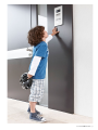
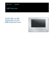
The front door is the gateway between
the outside world and your private living
space. The modern door communication
of ABB-Welcome now opens new
possibilities for both sides – overall comfort,
greater safety and stylistically matching
design. The system harmoniously adapts
to the architecture outdoors. In the
interior area it can be uniformly matched
with light switches and socket outlets.
User Manual ABB-Welcome | 3
Most welcome.
Intelligence with system.
4 | User Manual ABB-Welcome
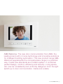
ABB-Welcome. The new door communication from ABB, the
leading brand with in home technology and innovative solutions
for intelligent building automation. The new product range ABBWelcome supplements the comprehensive range in a practical
way. It sets new standards as a holistic system. It combines
perfect design, comfort, efficiency and security. Living space
can now be consistently and uniformly designed. From the light
switch up to door communication. Inside and outside.
User Manual ABB-Welcome | 5
Door to door.
Technology and progress.
02
01
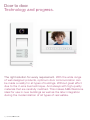
The right solution for every requirement. With the wide range
of well-designed products, optimum door communication can
be made a reality for all types of buildings. Without great effort
due to the 2-wire bus technique. And always with high-quality
materials that are carefully matched. This makes ABB-Welcome
ideal for use in new buildings as well as the later integration
during the modernization of all types of real estate.
6 | User Manual ABB-Welcome
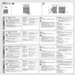
01 ABB-Welcome Video outdoor station
02 ABB-WelcomeTouch
03ABB-Welcome audio indoor station with handset
04ABB-Welcome audio indoor station with display
04
03
User Manual ABB-Welcome | 7
8 | User Manual ABB-Welcome
Contents
01 Examples for typical ABB-Welcome systems
10
02 Planning ABB-Welcome systems
14
03 Installation
30
04 Commissioning
36
05 Operation
42
06 Overview of product range
44
07 Connection diagrams
52
56
Legend
User Manual ABB-Welcome | 9
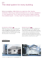
01
The ideal system for every building
More is possible. ABB-Welcome systems offer flexible
solutions. Planning is made as simple for you as are installation
or commissioning. The 2-wire bus technique makes possible
the suitable layout – to fully meet the requirements of the user.
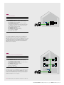
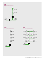
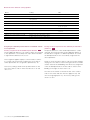
One-family house, audio/video Fig. 1
ABB-Welcome systems consist at least of a system controller,
outdoor station and indoor station. In Fig. 1 three indoor
stations are installed in the one house. When a visitor rings
the bell at the ABB-Welcome video outdoor station, the call
can be answered either at the ABB-WelcomeTouch, at the
ABB-Welcome audio indoor station with display or the ABBWelcome audio indoor station with handset.
Multifamily house, audio Fig. 2
Retrofitting an ABB-Welcome system in a multifamily house
with existing wiring is very easy. Even a plain bell system
can be converted to audio or video. Depending on the local
circumstances, an installation with recourse to a rising mains,
as shown in Figure 2, is recommended. The wires branch off
on each floor where the existing apartments are located –
to where an audio indoor station with handset is mounted.
There the user can answer incoming calls, open the door and
switch on the lights in the stairwell. Also floor call buttons can
be used. These are connected to the indoor station.
01One-family house
02 Multifamily house
01
10 Examples for typical ABB-Welcome systems | User Manual ABB-Welcome
02
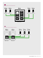
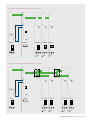
Fig. 1
One-family house/villa
»
System type: audio/video combined
»
Wiring: looped from device to device
»Devices used
» One ABB-Welcome video outdoor station, 1gang,
article number: 83121/1-xxx-500
» One ABB-Welcome audio indoor station with display,
article number: 83200 U-500,
cover plates article number: 83260-xxx-500 2gang frame
» One ABB-Welcome audio indoor station with handset,
article number: 83205 AP-xxx-500
» One ABB-WelcomeTouch,
article number: 83220 AP-xxx-500
» One ABB-Welcome system controller,
article number: 83300-500
» One electric door opener
S
The combined audio/video solution for the one-family house.
The drawing shows the easy-to-install 2-wire bus. From the
ABB-Welcome video outdoor station to the ABB-Welcome system
controller. And from there to the ABB-WelcomeTouch as well as
to the ABB-Welcome audio indoor station with display and the
ABB-Welcome audio indoor station with handset. Additional
distributors are not required.
Fig. 2
Multifamily house with 4 private apartments
»
System type: audio
»Wiring: rising mains with branch connections
»Devices used
» One ABB-Welcome audio outdoor station, 4gang,
article number: 83102/4-xxx-500
» Four ABB-Welcome audio indoor stations with handset,
article number: 83205 AP-xxx-500
» One ABB-Welcome system controller,
article number: 83300-500
» Four floor call buttons
» One electric door opener
The audio solution for the multifamily house. The drawing shows
the easy-to-install 2-wire bus From the ABB-Welcome outdoor
audio station to the ABB-Welcome system controller. And from
there to the ABB-Welcome audio indoor station with handset.
Additional distributors are not required
S
Note: Graphic symbols are explained in the legend on page 56.
User Manual ABB-Welcome | Examples for typical ABB-Welcome systems 11
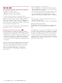
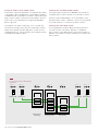
Multifamily house, audio/video Fig. 3
The setup of a video system or a combined audio/video
system can include an existing rising mains. To correctly
distribute the video image of the outdoor station inside the
house, flush-mounted video distributors are installed in each
branch box. Or MDRC units can be used in existing subdistributions.
Commercial object, audio/video Fig. 4
For buildings with several entrances (doctor's office, law firm,
small workshops, or similar), these can be individually equipped
with ABB-Welcome outdoor stations. A combination of ABBWelcome audio outdoor stations and ABB-Welcome video
outdoor stations is possible. For this a video outdoor distributor
as MDRC unit must be used. The door – from which the bell is
rung – is opened from the indoor station called.
01 Multifamily house
02 Commercial object
01
12 Examples for typical ABB-Welcome systems | User Manual ABB-Welcome
02
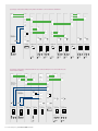
Fig. 3
Multifamily house with 6 private apartments
»
System type: audio/video combined
»Wiring: rising mains with branch connections, i.e. video
distributors
D
»Devices used:
» One ABB-Welcome video outdoor station,
6gang, article number: 83122/6-xxx-500
» Four ABB-Welcome audio indoor stations with handset,
article number: 83205 AP-xxx-500
» Two ABB-WelcomeTouch,
article number: 83220 AP-xxx-500
» ABB-Welcome system controller,
article number: 83300-500
» Three ABB-Welcome video distributors, FM indoor,
article number: 83320/2 U-500
» Six floor call buttons
» One electric door opener
D
D
The combined audio/video solution for the multifamily house
with six private apartments. The wiring from the ABB-Welcome
system controller to the indoor stations is designed as rising
mains. From here the wires branch off into the apartments. Each
of the two bottom floors has an ABB-Welcome audio indoor station with handset installed. All branch connections require video
distributors.
in
in
in
S
Fig. 4
Commercial object
»
System type: audio/video
»
Wiring: looped from device to device
»Devices used
» One ABB-Welcome video outdoor station, 1gang,
article number: 83121/1-xxx-500
» One ABB-Welcome audio outdoor station, 1gang,
article number: 83101/1-xxx-500
» One ABB-Welcome audio indoor station with display,
article number: 83200 U, cover plates article number:
83260-xxx-500 2gang frame
» One ABB-WelcomeTouch,
article number: 83220 AP-xxx-500
» One ABB-Welcome system controller,
article number: 83300-500
» One ABB-Welcome video outdoor distributor,
article number: 83325/2-500
» One ABB-Welcome bell transformer,
article number: 83315-500
» One switch actuator, door/light,
article number: 83330-500
» Two electric door openers
S
D
out
A
The combined audio/video solution for a building with several
entrances – such as private apartment and office. One indoor
station is located on the left at the office entrance, another one
on the right at the apartment. Inside the building the two internal
bus lines of the system controller are used. A distributor is
required to connect the two outdoor stations.
User Manual ABB-Welcome | Examples for typical ABB-Welcome systems 13
02
Assistance for planning.
Early advantage: With the planning aids for ABB-Welcome.
This makes even complex projects easy to manage and easy
to implement at a later stage.
The ABB-Welcome door communication can be used purely
as a 2-wire bus system in new buildings and for modernizing
existing systems. In most cases, the existing lines can be
used. The universally used 2-wire bus technology allows a
bell system to be upgraded to a video system with outdoor
camera.
An ABB-Welcome system can be set up purely as an audio
system. Visitors and residents use it to communicate with
each other between outdoor station and indoor station. Or
it can be a video system. This makes the camera image of
the video outdoor station visible on the ABB-WelcomeTouch.
Video and audio units can also be installed in the same
system. Also the later exchange of audio units with video
units, and the reverse, is possible.*
An ABB-Welcome system is made up of the following units:
»» One or more outdoor stations
»» One or more indoor stations
»» The system controller
» » And, if required, additional system devices
Equipping apartments and entrances with indoor or
outdoor stations
With an ABB-Welcome system buildings can be upgraded
from a one-family house to a large multifamily house. On the
one system up to 15 apartments with audio applications (up
to 12 apartments with video or mixed applications) can have
their own bell connected to the outdoor station.**
Up to four different indoor stations can be installed in each
apartment. They are assigned the same address and ring
simultaneously at an incoming call. Also several indoor
stations with different addresses can be installed in the
one private apartment.
In one ABB-Welcome system up to four different entrances
can be equipped with outdoor stations. The doors can be
opened remote-controlled. The associated lighti ng can also
be switched.
All units are connected with each other via the ABB-Welcome
2-wire bus.
* T he special system topology of a video system is to be observed (S. 20, Chapter. 02).
** T he actual number of apartments is limited by the available bell buttons.
14 Planning ABB-Welcome systems | User Manual ABB-Welcome
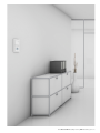
A flexible system. Also for residential buildings with
integrated medical and legal and other offices.
User Manual ABB-Welcome | Planning ABB-Welcome systems 15
Options of flexible addressing
Assigning doorbell push-buttons to apartments
The doorbell push-buttons of an outdoor station can be freely
assigned to an apartment. When the doorbell push-button is
pressed the call is received at the fixed address. The option
of flexible addressing allows the ABB-Welcome system to
be adapted to the individual requirements of the user. This
is a big advantage – especially when a system has several
outdoor stations.
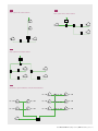
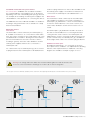
System controller and auxiliary power supply Fig. 7
The system controller supplies the other bus subscribers with
voltage and controls communication on the 2-wire bus. Starting from the system controller, the 2-wire bus divides into three
bus lines, the external bus and the two internal bus lines.
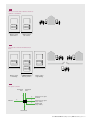
The use of several outdoor stations: uniform assignment
of call buttons Fig. 5
With several outdoor stations within an ABB-Welcome system
the call buttons of each outdoor station are generally assigned
similarly. This means that all apartments can be called from
all outdoor stations. This is practical for buildings with several
entrances – from each of which all apartments are accessible.
These hints should definitely be observed to prevent faults
from occurring during the audio and video transmission.
Several outdoor stations with different bell fields Fig. 6
Alternatively, the call buttons of the various outdoor stations
can be assigned differently when all apartments are to be
called from one outdoor station and only some apartments
from additional outdoor stations.
In the example an outdoor station is mounted at the gate
entrance with which all four apartments can be called. One
outdoor station is on the left building with apartments 01 and
02 and a further outdoor station on the right building with
apartments 03 and 04. This means that only two apartments
can be called from these two outdoor stations.
The use of several outdoor stations: assigning the
standard outdoor station
The ABB-Welcome system guarantees the opening of the
door at several outdoor stations at which the visitor has rung
the bell. The resident simply presses the button "Open door"
at the indoor station. Also the associated light at the entrance
can be switched on. Opening and switching in the apartment
is also possible without an existing outside call.
For several entrances with a system with outdoor stations, one
standard outdoor station is defined for opening the door and
switching the light. The setting is made at the indoor stations of
each apartment. With the ABB-WelcomeTouch the camera image
of an outdoor station can also be activated without having
received a call. Here the camera image of the standard outdoor
station is displayed.
* Detailed information about calculations, starting from page 24, Chapter 02.
16 Planning ABB-Welcome systems | User Manual ABB-Welcome
The ABB-Welcome system controller additionally offers options
for connecting a door opener and hallway or path illumination.
The switching times can be set on the device.
Notes:
» All branches of the wiring system should be terminated by
a connected bus device (e.g., an indoor station, outdoor
station or a system device). This means that no branches
are to be open.
» The system controller should not be installed in the
immediate vicinity of bell transformers or other switched
power supplies to prevent interference.
» Do not install the lines of the system bus together with
230 V cables.
» Connection cables for door openers should not be placed
in the same cable as the lines of the 2-wire bus.
» Avoid transitions between different cable types.
» In a cable with four or more wires, only one pair of wires
should be used for the 2-wire bus.
» When looping the 2-wire bus to a bus that is incoming or
outgoing from a device, it should not be installed in the
same cable.
» Internal and external bus must not laid in the same cable.
A system controller makes 65 consumer units available to the
ABB-Welcome. They are used to supply the connected devices.
In a one-family house, for example, this allows one video
outdoor station as well as up to four ABB-WelcomeTouch
to be operated.
In a multifamily house, for example, this allows a system with
one ABB-Welcome audio outdoor station with 15 bell buttons
and 30 audio indoor stations with handset (i.e. two per
apartment) to be operated by one system controller. For a
larger number of units an auxiliary power supply is required.*
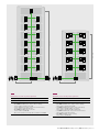
Fig. 5
The use of several outdoor stations: uniform assignment of call buttons
Apartment 01 A
Apartment 01 A
Apartment 02 B
Apartment 02 B
Apartment 03 C
Apartment 03 C
Outdoor station
Main entrance
Outdoor station
Side entrance
Fig. 6
Several outdoor stations with different bell
fields
A
Apartment 01Apartment
01 A
Apartment 01Apartment
A
01 A
Apartment 03Apartment
A
03 A
B
Apartment 02Apartment
02 B
B
Apartment 02Apartment
02 B
B
Apartment 04Apartment
04 B
Apartment 03Apartment
03 C
C
Apartment 04Apartment
04 D
D
Outdoor Outdoor
station station Outdoor Outdoor
station station Outdoor Outdoor
station station
Left building
Left building GatewayGateway
entranceentrance Right building
Right building
Fig. 7
The system controller
Internal bus
Line 1
Internal bus
Line 2
2
2
232 V AC
2
S
2
Electronic door opener
8-12V AC
2
Electronic door opener
(relay contact)
2
Hallway light
(relay contact)
2
External bus
User Manual ABB-Welcome | Planning ABB-Welcome systems 17
Auxiliary power supplies
Auxiliary power supplies can be connected to the internal bus
lines at any position. They serve for the connection of indoor
stations. One auxiliary power supply makes available 45 consumer
units. Neither they nor the connected devices put a load on the
system controller.
The use of auxiliary power supplies increases the number of
devices in a system. The maximum signal range – measured
from the system controller – is not increased. The indoor
stations can be connected to each of the four outputs of the
auxiliary power supply. A uniform distribution of the outputs is
recommended.
Cable type and signal ranges
The following cable types with a diameter of 0.8 mm are
recommended:
» » Telecommunication lines J-Y(St)-Y
» » Bell lines YR
»» Telecommunication lines for outdoor A-2Y(L)2Y
The following cable types should not be used:
» » Antenna cables
»» NYM cables
»» Riser cables
»» C able with a diameter smaller than 0.6 mm
The signal ranges for bus lines
The length of cables for the system controller to the remotest
indoor station or outdoor station must not exceed the following
values:
Bus lines
Connected
indoor or
outdoor stations
Signal range
External bus
Audio
300 m
External bus
Audio/Video
100 m*
Internal bus line 1
Audio
300 m
Internal bus line 1
Audio/Video
100 m
Internal bus line 2
Audio
300 m
Internal bus line 2
Audio/Video
100 m
*W
hen connecting only one ABB-Welcome video outdoor station to
the external bus line the signal range is 150 m.
Note: The two separate internal bus lines 1 and 2 permit the
setup of a pure audio line with a signal range of 300 m and
an audio/video line with a signal range of 100 m.
18 Planning ABB-Welcome systems | User Manual ABB-Welcome
Maximum number of devices per internal bus line
The maximum number of devices per internal bus line must
be observed. It is dependent on the power consumption of
the connected indoor stations:
Maximum number of
Connected device type indoor stations
Maximum cable length
between power supply and the remotest
indoor station
ABB-Welcome audio
indoor station with
handset
30 devices
300 m
ABB-Welcome audio
indoor station with
display
30 devices
100 m*
ABB-Welcome audio
indoor station with
display
6 devices
200 m*
ABB-Welcome audio
indoor station with
display
4 devices
300 m
ABB-Welcome IP
gateway for
Busch-ComfortTouch®
ABB-WelcomeTouch
4 devices
4 devices
100 m
100 m
*T
he shortened length of cable in comparison to the signal range of the
ABB-Welcome indoor audio station with display results from the increase
in current consumption in comparison to the ABB-Welcome audio indoor
station with handset. When the maximum number of devices at the system
controller is exceeded, an auxiliary power supply must be used. In turn, for
each of the four outputs of the auxiliary power supply the number of devices
and limits of cable length specified in the table apply.
Note: The maximum cable length specified applies to cables with
a diameter of 0.8 mm. For a diameter of 0.6 mm the length of
cable is halved.
Topology rules for the internal and external bus
Indoor stations, outdoor stations and system devices must
be connected to the system controller according to topology
rules for ABB-Welcome systems.
Topology rules for audio systems Topology rules for
Fig. 9
audio systems Fig. 8
For planning an ABB-Welcome audio system in which, next
to control information, only one audio signal is transmitted on
a 2-wire bus.
Audio system: Connection of devices on the internal bus
The following devices, aside from the system controller, are
usually connected to the internal bus of an audio system:
»» ABB-Welcome audio indoor station with handset
»» ABB-Welcome audio indoor station with display
»» ABB-Welcome auxiliary power supply
There are two options for wiring the devices: Looping and
branch line connections ("stub lines"). Both versions can be
combined within the one system.
Audio system: Looping the internal bus
For looping a continuous bus line the incoming and outgoing
2-wire bus is connected at each device as shown in Fig. 8.
A device must be connected to the end of the bus line – so
that the bus line does not remain "open". In all devices of the
audio system the terminal resistor should not be activated –
the switch "RC" is always on "OFF". Fig. 8
Audio system: Internal bus stub lines
As an alternative to looping, the devices can also be
connected at the end of a branch line or stub line:
»» ABB-Welcome audio indoor station with handset
»» ABB-Welcome audio indoor station with display
»» ABB-Welcome auxiliary power supply
An example of this layout: A rising mains in a building
connects the floors and the stub lines branch off on the
floors. Fig. 9
A topology with a rising mains and several stub lines can
easily be set up in an audio system. Here the bus lines are
switched parallel to the branch connections.
Note: For all devices the terminal resistor should not be
activated – the switch "RC" is always on "OFF".
Fig. 8
Fig. 9
Audio system: Looping the internal bus
RC – OFF
Audio system: Internal bus stub line
RC – OFF
AUDIO
RC – OFF
AUDIO
AUDIO
AUDIO
AUDIO
AUDIO
RC – OFF
RC – OFF
RC – OFF
RC – OFF
AUDIO
S
AUDIO
AUDIO
RC – OFF
AUDIO
RC – OFF
AUDIO
RC – OFF
AUDIO
RC – OFF
RC – OFF
AUDIO
S
AUDIO
User Manual ABB-Welcome | Planning ABB-Welcome systems 19
Audio system: Connection of devices to the external bus
Fig. 10
The following devices, aside from the system controller, are
usually connected to the external bus of an audio system:
» » ABB-Welcome audio outdoor station
» » Switch actuator, door/light
Up to four outdoor stations can be connected. For each of
these, two switch actuators for opening doors and switching
lights can be used. When installing only one outdoor station,
the door opening or light function of the system controller can
be used.
The connection is made directly on their external bus. With
two or more outdoor stations, star-shaped wiring is to be
selected. The star point is to be located as close to the
system controller as possible. Fig. 10
It is irrelevant whether the external bus is terminated from an
audio outdoor station or a switch actuator.
Note: Neither the ABB-Welcome audio outdoor station nor
the switch actuator have a switch for the terminal resistor.
Topology rules for video systems
An ABB-Welcome video system with transmission of the
control information, of the audio signal as well as the video
signal is planned as follows:
Video system: Connection of devices on the internal bus
The devices used for setting up an audio system can also be
used for setting up a video system. This means system
controller, ABB-Welcome audio outdoor station and audio
indoor station. And, depending on the layout, the following
devices are additionally connected to the internal bus.
» » ABB-WelcomeTouch
»» ABB-Welcome IP gateway
»» Video indoor distributor
Video system: Looping the internal bus Fig. 11
The 2-wire bus for a video system can be looped from device
to device similar to an audio system. This results in a continuous
bus line.
The terminal resistor must be activated on the last device of
the bus line – the switch "RC" is set to "ON". For all other
devices the switch is set on "OFF".
Video system: Internal bus stub lines Fig. 12
As an alternative to looping, the devices can also be
connected at the video system via stub line. In this case a
video distributor is to be used on all branch connections.
The video indoor distributor exist as MDRC unit for mounting
in a sub-distribution or as built-in device for flush-mounted
installation in a branch box. The terminal resistor must be
activated on the last device of each stub line and at the end
of the riser main – the switch "RC" is set to "ON".
20 Planning ABB-Welcome systems | User Manual ABB-Welcome
Fig. 10
Audio system: Two outdoor stations
RC – OFF
AUDIO
RC – OFF
AUDIO
S
AUDIO
A
AUDIO
Fig. 11
Fig. 12
Video system: Looping the internal bus
RC – ON
Video system: Internal bus stub lines
D
RC – ON
VIDEO
AUDIO
RC – OFF
D
RC – ON
AUDIO
VIDEO
RC – OFF
D
RC – ON
VIDEO
AUDIO
RC – OFF
D
RC – ON
AUDIO
AUDIO
in
RC – ON
in
RC – OFF
in
RC – OFF
in
RC – OFF
RC – ON
AUDIO
RC – ON
AUDIO
RC – ON
VIDEO
RC – ON
AUDIO
S
S
VIDEO
VIDEO
User Manual ABB-Welcome | Planning ABB-Welcome systems 21
Video system: Connection of devices on the external bus
Fig. 13
Fig. 14
Fig. 15
The following devices, aside from the system controller and
the previously listed devices, are usually connected to the
external bus of an video system:
» » ABB-Welcome video outdoor station
» » ABB-Welcome video outdoor distributor
For a video system only, branch connections with one
outdoor video distributor each are permitted for wiring several
ABB-Welcome video outdoor stations. Additional devices –
such as the corridor/light switch actuators or ABB-Welcome
audio outdoor station – can be connected via looping. For
systems with up to four ABB-Welcome video outdoor stations
we recommend the topologies shown.
It is irrelevant whether the external bus is terminated from an
audio outdoor station or a switch actuator.
Utilization of the two internal bus lines Fig. 16
Two internal bus lines can be connected to the system
controller via the two terminal pairs. Depending on the layout
of the building, the following divisions are recommended:
» » All devices are connected to an internal bus line. The second
internal bus line remains unoccupied for later applications.
»» T he devices are distributed uniformly on the two internal
bus lines. This allows two rising mains to be implemented,
for example.
For the second version one internal bus line can be used for
audio only. This is wired according to the rules for audio
systems. No video distributors are required on the branch
connections and the terminal resistors are to be set on
"OFF". The other internal bus line – for video and, if
necessary, for audio – is to be wired according to the
rules for video.
22 Planning ABB-Welcome systems | User Manual ABB-Welcome
The following applies to the system limits:
» » When calculating the consumer units, all devices without
a power supply that are connected to the internal bus line
must be taken into consideration.
» » For a pure audio internal bus line the signal range is 300 m.
» » For a video internal bus line the signal range is 100 m.
»» For each internal bus line the upper limits for the device
apply which are listed in the Table on page 18, Chapter 02.
Notes:
»» The twisted pairs of both internal bus lines must not be
installed in the same cable.
»» The two internal bus lines must not be connected together.
Connection of floor call buttons
In multifamily houses the floor call buttons for ringing at the
apartment door are mostly installed in the stairwell or corridor.
In an ABB-Welcome system a floor call button for connecting
to an indoor station is provided for each apartment. If available,
two wires of the cable can be used, which also includes the
2-wire bus. The maximum distance from the indoor station
to the floor call button can be 50 metres. When the button
is pressed all indoor stations will ring. At the indoor station a
separate bell sound can be selected for the floor call and the
call from the outdoor station.
Fig. 13
Fig. 14
Video system: Two outdoor stations
Video system: Three outdoor stations
S
VIDEO
D
VIDEO
out
D
out
A
VIDEO
VIDEO
A
VIDEO
S
A
VIDEO
D
VIDEO
out
Fig. 15
Video system: Four outdoor stations
S
D
A
D
out
VIDEO
out
A
D
VIDEO
out
A
VIDEO
VIDEO
Fig. 16
Audio/video system: Utilization of the two internal bus lines
D
RC – ON
AUDIO
RC – OFF
RC – OFF
AUDIO
AUDIO
AUDIO
AUDIO
RC – OFF
D
RC – ON
VIDEO
RC – OFF
D
RC – ON
AUDIO
in
RC – ON
in
RC – OFF
in
RC – OFF
RC – ON
VIDEO
RC – ON
AUDIO
RC – ON
AUDIO
S
VIDEO
User Manual ABB-Welcome | Planning ABB-Welcome systems 23
Planning simple systems
One-family house with four indoor stations Fig. 17
An ABB-Welcome system with up to four indoor stations can
be set up in a one-family house without further calculation.
Also up to four ABB-WelcomeTouch can be connected to the
system controller.
Multifamily houses
The following table serves to calculate the maximum number
of devices with power supply in multifamily houses.
Note: The table applies only to apartments with one to two
indoor stations.
Calculation of consumption for system controller
Device
Number
Consumption units
Number x
Consumer units
Indoor stations
ABB-Welcome audio indoor station with handset
1
ABB-Welcome audio indoor station with display
2
ABB-WelcomeTouch
11
ABB-Welcome IP gateway for Busch-ComfortTouch®
11
Video outdoor stations
ABB-Welcome video outdoor station, 1gang, 2gang, 3-gang
8
ABB-Welcome video outdoor station, 4gang, 6gang
10
ABB-Welcome video outdoor station, 8gang, 12gang
13
Audio outdoor station
ABB-Welcome audio outdoor station, 1gang, 2gang, 3-gang
5
ABB-Welcome audio outdoor station, 4gang, 6gang
6
ABB-Welcome audio outdoor station, 10gang, 15gang
11
System devices
ABB-Welcome door/light switch actuators
2
Only for two indoor stations per apartment
Number of apartments with two audio indoor stations
1 or 2
Number of apartments with one audio indoor station and one
ABB-WelcomeTouch
1 or 2
Number of apartments with two ABB-WelcomeTouch
Must not be
considered
Total number of consumer units
must not exceed 65
24 Planning ABB-Welcome systems | User Manual ABB-Welcome
Must not
be
considered
"1 or 2": If an ABBWelcome audio
indoor station with
display is installed in
the apartments, please
attach 2 consumer
units; otherwise attach
only 1 consumer unit.
The following table serves to calculate the maximum number
of devices with auxiliary power supply in multifamily houses.
Note: The table applies only to apartments with one to two
indoor stations.
Consumption calculation for auxiliary power supply
Device
Number
Consumer units
Number x
Consumer units
Indoor stations
ABB-Welcome audio indoor station with handset
1
ABB-Welcome audio indoor station with display
2
ABB-WelcomeTouch
11
ABB-Welcome IP gateway for Busch-ComfortTouch®
11
Only for two indoor stations per apartment
Number of apartments with two
ABB-Welcome audio indoor stations
1 or 2
Number of apartments with one ABB-Welcome
audio indoor station and one ABB-WelcomeTouch
1 or 2
Number of apartments with two ABB-WelcomeTouch
Must not be
considered
"1 or 2": If an ABBWelcome audio
indoor station with
display is installed in
the apartments, please
attach 2 consumer
units; otherwise attach
only 1 consumer unit.
Must not
be
considered
Total number of consumer units
must not exceed 45
Fig. 17
Single-family house
»
System type: audio/video combined
»
Wiring: looping
»
Devices used:
» One ABB-Welcome video outdoor station, 1gang,
article number: 83121/1-xxx-500
» One ABB-Welcome audio indoor station with display,
article number: 83200 U-500, cover plates,
article number: 83260-xxx-500, 2gang frame
» One ABB-Welcome audio indoor station with handset,
article number: 83205 AP-xxx-500
» One ABB-WelcomeTouch,
article number: 83220 AP-xxx-500
» One Busch-ComfortTouch®
» One IP gateway for Busch-ComfortTouch®,
article number: 83340-500
» One ABB-Welcome system controller,
article number: 83300-500
S
Max. 150 m
IP
Max. 100 m
User Manual ABB-Welcome | Planning ABB-Welcome systems 25
Multifamily houses with 15 private apartments, in each
apartment: one ABB-Welcome audio indoor station with
handset Fig. 18
Calculation of consumption for system controller
Device
Number
Consumer units
Number x
Consumer units
15
1
15
2
11
22
1
2
2
Indoor stations
ABB-Welcome audio indoor station with handset
Audio outdoor station
ABB-Welcome audio outdoor station, 15gang
System devices
ABB-Welcome door/light switch actuators
Total number of consumer units
must not exceed 65
39
The consumer units required are covered by the system
controller. The maximum number of devices per internal bus
line is not exceeded. No auxiliary power supply required.
Multifamily houses with 10 private apartments, in each
apartment: one ABB-Welcome audio indoor station with
display and one ABB-Welcome audio indoor station with
handset Fig. 19
Calculation of consumption for system controller
Number
Consumer units
Number x
Consumer units
ABB-Welcome audio indoor station with handset
10
1
10
ABB-Welcome audio indoor station with display
10
2
20
1
11
11
Device
Indoor stations
Audio outdoor station
ABB-Welcome audio outdoor station, 10gang
Only for two indoor stations per apartment
Number of apartments with two
ABB-Welcome audio indoor stations
10
Total number of consumer units
must not exceed 65
The required number of consumer units are covered by the
system controller. The maximum number of devices per
internal bus line is not exceeded. The maximum lenghth is
100 m. No additional auxiliary power supply is necessary.
26 Planning ABB-Welcome systems | User Manual ABB-Welcome
1 or 2: 2
20
61
"1 or 2": If an ABBWelcome audio indoor
station with display is
installed, please attach 2
consumer units;
otherwise attach only
1 consumer unit.
Max. 100 m
Max. 300 m
S
S
A
Max. 300 m
Max. 300 m
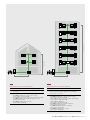
Fig. 18
Multifamily house with 15 private apartments
»
System type: audio
Fig. 19
Multifamily house with 10 private apartments
»
System type: audio
»Wiring: rising mains with branch connections to the apartments
»Wiring: rising mains with branch connections to the apartments
»Devices used:
» One ABB-Welcome audio outdoor station, 15gang,
article number: 83105/15-xxx-500
» Fifteen ABB-Welcome audio indoor stations with handset,
article number: 83205 AP-xxx-500
» One ABB-Welcome system controller,
article number: 83300-500
» One switch actuator, door/light, article number: 83330-500
»Devices used:
» One ABB-Welcome audio outdoor station, 10gang,
article number: 83105/10-xxx-500
» Ten ABB-Welcome audio indoor station with display,
article number: 83200 U-500, cover plates,
article number: 83260-xxx-500, 2gang frame
» Ten ABB-Welcome audio indoor stations with handset,
article number: 83205 AP-xxx-500
» One ABB-Welcome system controller,
article number: 83300-500
User Manual ABB-Welcome | Planning ABB-Welcome systems 27
Multifamily house with 4 apartments, in each apartment:
one ABB-WelcomeTouch Fig. 20
Calculation of consumption for system controller
Device
Number
Consumer units
Number x Consumer units
4
11
44
1
10
10
Indoor stations
ABB-WelcomeTouch
Video outdoor stations
ABB-Welcome video outdoor station, 4gang
54
Total number of consumer units must not exceed 65
The consumer units required are covered by the system
controller. The maximum number of devices per internal bus
line is not exceeded. No auxiliary power supply required.
Multifamily houses with 12 private apartments, in each
apartment: one ABB-WelcomeTouch and one ABBWelcome audio indoor station with handset Fig. 21
Calculation of consumption for system controller
Number
Consumer units
Number x
Consumer units
ABB-Welcome audio indoor station with handset
12
1
12
ABB-WelcomeTouch
12
11
132
1
13
13
Device
Indoor stations
Video outdoor stations
ABB-Welcome video outdoor station, 12gang
Only for two ABB-Welcome indoor stations per
apartment
Number of apartments with one audio indoor station and
one ABB-WelcomeTouch
12
1 or 2: 1
Total number of consumer units must not exceed 65
The consumer units required are covered by the system
controller (65 consumer units) and the five auxiliary power
supplies (5x45=225). The maximum number of devices of the
internal bus line and the maximum number of outputs of the
auxiliary power supplies are not exceeded.
28 Planning ABB-Welcome systems | User Manual ABB-Welcome
12
169
"1 or 2": If an ABBWelcome audio indoor
station with display is
installed, please attach
2 consumer units;
otherwise attach only
1 consumer unit.
D
in
PS
PS
D
in
PS
in
PS
Max. 100 m
D
S
S
Max. 150 m
Fig. 20
Multifamily house with 4 private apartments
»
System type: video
»Wiring: rising mains with video distributors at the branch
connections
»Devices used:
» One ABB-Welcome video outdoor station, 4gang,
article number: 83122/4-xxx-500
» Four ABB-WelcomeTouch, article number: 83220 AP-xxx-500
» Two ABB-Welcome video distributors, FM indoor, article
number: 83320/2 U-500
» One ABB-Welcome system controller,
article number: 83300-500
Max. 100 m
PS
Max. 150 m
Fig. 21
Multifamily house with 12 private apartments
»
System type: video
»Wiring: Rising mains with five auxiliary power supplies at the
branch connections; a video distributor is located at the
topmost branch connection
»Devices used:
» One ABB-Welcome video outdoor station, 12gang,
article number: 83124/12-xxx-500
» Twelve ABB-Welcome audio indoor stations with handset,
article number: 83205 AP-xxx-500
» Twelve ABB-WelcomeTouch,
article number: 83220 AP-xxx-500
» One ABB-Welcome video distributor, FM indoor,
article number: 83320/2 U-500
» Five ABB-Welcome auxiliary power supplies,
article number: 83310-500
» One ABB-Welcome system controller,
article number: 83300-500
User Manual ABB-Welcome | Planning ABB-Welcome systems 29
03
Expert installation.
General information for the installation of an ABB-Welcome
system in new and existing buildings. The installation of flushmounted and surface-mounted devices as well as MDRC units
is described in detail in the operating manuals of the devices.
Installation instructions for new buildings
The following should be ensured when setting up a reliable,
simple, economical and future-oriented ABB-Welcome
system:
» » T he use of telecommunication cables J-Y(St)-Y in the
indoor and A-2Y(L)2Y in the outdoor area with a diameter
of 0.8 mm. In addition to the wire pair of the ABB-Welcome
2-wire bus, other pairs of wires can be kept as "reserve"
in the same cable. For example, for later connection to a
Busch-Watchdog movement detector in the outdoor area
or as power supply for future bus devices.
» » F or smaller systems: Looping the internal bus from device
to device
» » F or larger systems: Setup of a structure with a rising mains
and several stub lines. If two rising mains are provided, the
two internal bus lines can be used.
An ABB-Welcome audio system should make later
conversion to video easy. The conversion includes the
exchange of at least one ABB-Welcome audio outdoor
station with an ABB-Welcome video outdoor station and
at least one ABB-Welcome audio indoor station with an
ABB-WelcomeTouch. The system controller need not be
replaced.
For branch connections in the system, video distributors
must be installed for the conversion. These are not required
in the internal bus – if it is looped from device to device.
The setting of the terminal resistors of the system must be
checked after the conversion (See 20, Chapter 02).
Part of daily life. The ABBWelcomeTouch in new buildings.
30 Installation | User Manual ABB-Welcome
User Manual ABB-Welcome | Installation 31
Installation instructions for modernization
The modernization of a building is an ideal opportunity for
replacing an existing intercom with a modern ABB-Welcome
system within the design of the other electrical installations.
Here, as a rule – independent of the type of wiring of the old
system (pure bell system, intercom in "1+n“ technology or
comparable systems, 2-wire bus technique) – existing lines can
be used. In case of existing cable material a possible reduction
of the transmission range is to be checked.
It is recommended not to install the bus lines and power
supply for the electric door opener in the same cable, since
this may impair the quality of the picture in video systems.
We additionally recommend the use of high-impedance door
openers.
Conversion of old bell systems in one-family houses to
ABB-Welcome
Available:
» » At the door: one bell
» » Indoors: one gong
»» In the sub-distribution: one transformer for the gong and
the name plate
The conversion of the bell system in a one-family house to an
ABB-Welcome system is easy if a cable is available from the
front door to the distribution and a cable from the distribution
into the building, e.g. in the hallway. This layout is used by the
system controller, outdoor station and indoor station.
This enables buildings with only a bell system to be retrofitted
with audio or video systems.
32 Installation | User Manual ABB-Welcome
The conversion of old bell and intercom systems to ABBWelcome ("1+n" technique, with coaxial cable for video if
necessary) The multifamily house has available:
»At the door: bells (with "1+n" wiring) + loudspeakers /
microphones
»» Indoors: in each apartment, one indoor station with gong
and a button for opening the front door
»» In the sub-distribution: one bell transformer for the buzzer/
electronic door opener, one transformer for the house
telephones
For systems with "1+n" wiring as rising mains installation with
branch connections to the indoor stations only two wires are
required from the multi-wire cable. The indoor stations of the
ABB-Welcome system are also connected to the rising mains
via the branch line. For a video system one indoor FM video
distributor should be installed in the branch box.
The layout of a system in "1+n" wiring as star-shaped
installation – which comes from the main distribution, for
example – can easily be used in an ABB-Welcome system.
Here all cables to the indoor stations are connected to
the system controller. For a video system, indoor MDRC
video distributors must additionally be installed. For an
existing "1+n" system without system controller a two-wire
cable must be laid from the outdoor station to the system
controller. Usually an existing cable can be used here.
01
02
03
04
05
06
ABB-Welcome outdoor stations
01 ABB-Welcome video outdoor station, 1gang,
dimensions in mm (H x W xD): 277 x 135 x 43,
article number: 83121/1-664-500
02 ABB-Welcome video outdoor station, 6gang,
dimensions in mm (H x W xD): 349 x 135 x 43,
article number: 83122/6-664-500
03 ABB-Welcome video outdoor station, 12gang,
dimensions in mm (H x W xD): 277 x 235 x 43,
article number: 83124/12-664-500
04 ABB-Welcome audio outdoor station, 1gang,
dimensions in mm (H x W xD): 205 x 135 x 29,
article number: 83101/1-664-500
05 ABB-Welcome audio outdoor station, 6gang,
dimensions in mm (H x W xD): 277 x 135 x 29,
article number: 83102/6-664-500
06 ABB-Welcome audio outdoor station, 15gang,
dimensions in mm (H x W xD): 277 x 235 x 29,
article number: 83105/15-664-500
User Manual ABB-Welcome | Installation 33
Installation of the outdoor stations Fig. 22 Fig. 23
For all outdoor stations an installation wall box of matching
colour is available for flush-mounting or surface-mounting.
Surface-mounting is suitable for all types of walls, whether
rendered, clinker or cavity wall. They are recommended
particularly for walls with a thermal sandwich system. Here
the use of suitable mounting material should be ensured.
Also flush-mounting is possible on the same wall types,
because the installation socket has a full perimeter frame.
For flush-mounting in a cavity wall (thickness between 2 and
25 mm) a cavity wall mounting set consisting of mounting
anchors is available.
To make plastering easy after a cavity has been cut into of
the wall for flush-mounted installation a mounting accessory
is available. This is inserted in the cavity and removed again
after plastering is completed. The flush-mounting box can
then be installed.
For dismantling the end strip, a distance of 1 cm should be
kept to the right of the outdoor station.
To be able to change the name plates while the outdoor
station is mounted, a distance of 10 cm should remain free
below the outdoor station. If this is not possible the outdoor
station must be removed from the installation socket to
change the name plates.
Fig. 22
Note: The camera of the ABB-Welcome video outdoor station
should not face powerful light sources, such as street lights.
This should be taken into consideration when choosing the
correct position for mounting. Lamps in the entrance area
should uniformly illuminate the face of the visitor. The
recommended installation height is 1.50 m. This optimally
captures persons of average body size. Bright or backgrounds
with a deep contrast should be avoided. It could reduce the
quality of the picture.
Installation of indoor stations
The ABB-Welcome audio indoor station with handset and
the ABB-WelcomeTouch are easy to install as a surfacemounted device with the aid of the enclosed mounting frame.
The devices can also be mounted on a commercially available
58 flush-mounted wall box.
The ABB-Welcome audio indoor station with display can be
installed in the design of various switch programs and so
adapts to the other light switches and socket outlets in an
apartment. Two 58 flush-mounted wall boxes are required for
the installation.
Additional information is contained in the operating manuals.
The associated QR codes are listed starting from page 46.
Fig. 23
The distance zones for the installation of the
outdoor station
Detection angle of camera
0.4 m
1 cm
1.12 m
0.4 m
0.6 m
+
– 15°
10 cm
Distance zone
-15°
34 Installation | User Manual ABB-Welcome
0.6 m
0.6 m
+15°
0.6 m
Installation instructions for system devices
Recommendation: All MDRC units should be mounted in
the central distribution of the building. This can be altered
depending on the size of the building and topology selected.
For example, when installing an auxiliary power supply in the
sub-distribution of the apartment, for connecting the devices.
The ABB-Welcome indoor FM video distributor is suitable for
mounting in rising mains below a floor call button in a deep
flush-mounted wall box.
Wiring the devices
Internal bus
The internal bus is wired continuously via terminal pairs a1/
b 1 available on the devices. To connect the two internal bus
lines, the system controller has two terminal pairs a1/b1. They
are labelled OUT 1 and OUT 2. Starting from these terminal
pairs the internal bus lines are fed to the indoor stations,
including IP gateway, the indoor video distributors and the
auxiliary power supplies and there also connected to a
terminal pair a1/b1.
For a device with only one terminal pair a 1/b1 this is used for
looping the bus line. Also terminal pairs a 1/b1 labelled IN are
used for looping the bus line on indoor video distributors and
the auxiliary power supply.* The stub line of the bus line is
connected to the terminal pairs a1/b1 labelled OUT 1 to 4.
External bus
The external bus is wired continuously via the terminal pairs
a2/b2 available on the devices. The system controller has a
terminal pair a2/b2 labelled IN to connect the external bus line.
To these the external bus lines to the outdoor stations, the
outdoor video distributors and the switch actuators are connected.
The terminal pairs a2/b2 labelled IN 1 and IN 2 are used on
the outdoor video distributors for connecting the bus lines
coming from the outdoor stations. The terminal pair a2/b2
labelled OUT is used for connecting the bus line going to the
system controller. Only one terminal pair a2/b2 is available on
the door/light switch actuator. It is used for looping the bus line.
Additional terminal pairs
All additional terminal pairs – for connecting an electronic
door opener or floor call button – are explained in the operating
manuals of the respective devices. Additional connecting
diagrams are available as example on pages 52 to 53.
0.4 m
1.12 m
0.4 m
Warning: Low-voltage and 230 V cables must not be installed together in a flush-mounted socket.
In case of a short-circuit there is the danger of a 230 V load on the low-voltage line.
0.6 m
+
– 15°
* A n exception is the indoor FM video distributor, which contains two internally bridged terminal pairs a1/b1 labelled IN for more practical wiring.
-15°
0.6 m
0.6 m
1.5 m
1.10 m
1.90 m
0.82 m
+15°
0.6 m
1.70 m
1.30 m
2.18 m
User Manual ABB-Welcome | Installation 35
04
Basic settings
Well-prepared for everything. Several settings need to be made
prior to the installation of an ABB-Welcome system. These can
be carried out by the electrical installer already at the factory,
so that the devices can be directly installed at the customer's
premises.
The following settings are to be carried out.
Setting the address of the outdoor station: Fig. 24
The allocation to one of the four inputs of the ABB-Welcome
system is made on the outdoor stations and the associated
switch actuators for door and light via the setting of the
address.
outdoor station or the front of the MDRC switch actuator.
Setting the button sounds on/off
On the outdoor stations the acoustic feedback signal is
switched on and off via the "TT" button sounds switch when
a doorbell button is pressed. The switch is located on the
rear of the outdoor station.
Here the rotary knob house/outdoor is set on an address
between 1 and 4. The knob is located on the rear of the
Comfortable for the electrical installers.
Setting in the workshop. Installing at the building and in the apartment.
Fig. 24
Rotary knob for setting the address of an
outdoor station
Top
Address
Outdoor station
K10
5 6
2 3
4
7 8
2 3
5 6
7 8
9
0 1
7 8
2 3
4
0 1
5 6
9
4
TT
K1
9
0 1
36 Commissioning | User Manual ABB-Welcome
K10
Bell button
Tens digit
K1
Bell button
Single digit
TT
Button sounds
(ON = active)
ON
User Manual ABB-Welcome | Commissioning 37
Overview of the different setting options
Device
Setting
ABB-Welcome outdoor station
Address of the outdoor station
Note
Button sounds on/off
Assigning the doorbell buttons to
the apartments
ABB-Welcome indoor station
Only if the specified allocation is different
Address of the indoor station
Setting of the terminal resistor
Setting of the standard outdoor station
Only if several outdoor stations are used
in the one system
Setting of the main indoor station
ABB-Welcome system controller
Setting of the door opener times and light times
ABB-Welcome video indoor distributor
Setting of the terminal resistor
ABB-Welcome Switch actuator, door/light
Address of the associated outdoor station
Only if the door opener and light switch
are used
Setting of the door opener or light switch
Setting of the door opener times and light times
Assigning the doorbell push-button of an outdoor station
to an apartment
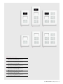
Factory assignment of the doorbell push-buttons Fig. 25
The doorbell push-buttons of an outdoor station are assigned
to the apartments consecutively from top to bottom and left
to right with the addresses 01, 02, etc.
This assignment applies equally to several outdoor stations
in a system. This means that in Figure 26 in each outdoor
station push-button A is assigned to apartment 01, etc.
This factory setting is fixed via two potentiometers on the
rear of the outdoor station. "K10" must be set on "0" and
"K1" on "1".
Change in the assignment of the doorbell push-buttons
("Offset") Fig. 27
The preset addresses of the doorbell push-buttons can be
changed. This means that the top doorbell push-button on
the left side is assigned to a different apartment. The other
doorbell push-buttons are consecutively assigned to the
other apartments.
Figure 27 shows the three outdoor stations from the example
on page 16. The outdoor station at the gate entrance and the
outdoor station at the left building show the factory assignment
of the doorbell push-buttons. At the outdoor station of the
building on the right an offset of 03 is set.
The value of the "Offset" is fixed at the rear of the outdoor
station. Here "K10" indicates the tens digit (here "0") and
"K1" the single digit (here "3"). The factory setting of the
offset is on "01".
38 Commissioning | User Manual ABB-Welcome
Fig. 25
Factory assignment of doorbell push-buttons
STATION X10
1
0
X1
STATION X10
2
1
0
X1
1
1
K10
K1
0
1
STATION X10
1
X1
0
9
STATION X10
1
1
X1
0
Apartment 05 E
Apartment 06 F
Apartment 02
Apartment 01
Apartment 09
Apartment 01 A
Apartment 07 G
Apartment 02 B
Apartment 08 H
Apartment 03 C
Apartment 09
Apartment 04 D
Apartment 10 J
Apartment 10
I
Outdoor station
Fig. 26
Several outdoor stations with identical assignment
1
K10
K1
0
1
2
K10
K1
0
1
STATION X10
1
0
X1
1
Apartment 01
Apartment 01 A
Apartment 01 A
Apartment 02 B
Apartment 02 B
Apartment 03 C
Apartment 03 C
Outdoor station
Main entrance
Outdoor station
Side entrance
STATION X10
1
0
X1
2
Apartment 02
STATION X10
1
0
X1
3
Apartment 03
User Manual ABB-Welcome | Commissioning 39
Setting the address of the indoor station
At the indoor stations the apartment is assigned via the setting
of the address. Up to 99 apartments can be addressed within
an ABB-Welcome system. Up to four indoor stations with equal
rights can be located in each with the same address. The four
indoor stations are called when the assigned doorbell pushbutton is pressed.
Setting of the "standard outdoor station"
For several outdoor stations in an ABB-Welcome system the
"standard outdoor station" must be set on the indoor stations.
The address of an indoor station (e.g. "15") is set with the
aid of the rotary knobs "X10" and "X1" at the indoor stations,
where "X10" specifies the tens digit (here "1") and "X1" the
single digit (here "5"). The rotary knobs are located at the rear
or outside of the indoor stations.
Setting of the main indoor station
In each apartment the switch "M/S" must be activated on
one indoor station. This means "M=ON". For additional
indoor stations in the apartment the switch here must be on
"M=OFF". The switch is located on the back or outside of the
indoor stations.
Here the rotary knob STATION is set on the address of the
standard outdoor station – between 1 and 4. The rotary knob
is located at the rear or outside of the indoor stations.
Fig. 27
Several outdoor stations with identical
assignment
STATION X10
2
0
X1
2
Apartment 02
STATION X10
2
0
X1
1
2
K10
K1
0
1
1
K10
K1
0
1
3
K10
K1
0
3
Apartment 01
3
0
X1
3
Apartment 03
Apartment 01 A
Apartment 01 A
Apartment 02 B
Apartment 02 B
Outdoor station
Left building
40 Commissioning | User Manual ABB-Welcome
STATION X10
Apartment 03 C
Apartment 03 A
Apartment 04 D
Apartment 04 B
Outdoor station
Gateway entrance
Outdoor station
Right building
STATION X10
3
0
X1
4
Apartment 04
Setting of the terminal resistor
As described in Chapter 02, the terminal resistor in ABBWelcome audio only systems is always switched to "OFF".
For video systems, the terminal resistors are to be switched
to "ON" for the last devices of a branch and to "OFF" for all
others.
The terminal resistors are set via the switch "R/C" on all
indoor stations as well as video indoor distributors and
auxiliary power supplies.
Setting of the door opener or light switch
The setting is only made on the door/light switch actuator. It
shows the respective function of the device in the ABB-Welcome system. The sliding switch on the device is used
for setting.
Setting of the door opener times and light times
This setting on the system controller and the door/light
switch actuator determines the operating period of the door
buzzer (from one to ten seconds). The light-on period can be
set between one second and five minutes.
A separate potentiometer for both is located on the system
controller. In case of the switch actuator the same potentiometer
is used for one of the two control values depending on the
position of the sliding switch.
User Manual ABB-Welcome | Commissioning 41
05
Control and system behaviour
Always intuitively correct. ABB-Welcome systems make this
possible from the very first contact. Because the eyes, hands
and ears quickly orient themselves. In this way the intelligent
system fulfils individual wishes and requirements.
Operating the outdoor and indoor stations
The ABB-Welcome outdoor and indoor stations are operated
intuitively. Familiar style elements and easy-to-understand
icons are used. For the ABB-WelcomeTouch and the ABBWelcome audio indoor station with display the intelligent
menu structure is used.
The functions of all devices are described in the respective
operating manuals.
System behaviour
The digital technology of an ABB-Welcome system offers the
user a large variety of options.
A connection can be established by ringing the bell on the
outdoor station. Or it can be established at the indoor station
by switching on the microphone and/or the camera of the
outdoor station. A connection lasts at the most two minutes
after which it is automatically terminated.
To guarantee that no call of a visitor is missed at an outdoor
station, the two following simple rules apply:
»» Connections that are established at the outdoor station
always have a higher priority than existing connections. This
means that an existing connection is interrupted as soon as
the bell is rung at the outdoor station.
»» A resident cannot establish a connection to an outdoor
station if one already exists. An occupied ABB-Welcome
system is displayed on the indoor stations.
The floor call buttons can be rung irrespective of an existing
connection between outdoor and indoor station. Depending
on the work load of the ABB-Welcome system, settings can
be carried out on several indoor stations. If the system is
occupied, this is indicated at the indoor station.
In front of the door and behind
the door. Intuitive operability. For
visitors and residents.
42 Control | User Manual ABB-Welcome
User Manual ABB-Welcome | Control 43
06
Design and technology in full harmony.
The ABB-Welcome product range is innovative, sets standards in
design, function and technique. It offers high-quality design,
attractive colours and numerous intelligent functions. It raises the
quality of life in every area of the house. All products are designed
to harmonize perfectly, so that living space can be uniformly
designed throughout the home. From light switches to socket
outlets and up to door communication. This makes the new door
communication from ABB not only outstandingly attractive, but
also convincingly comfortable. And clear operating instructions
with the most important technical data assist in the safe and
faultless installation. More about the latest door communication
you will also discover with our QR-Code service.
Living space perfectly designed.
With ABB-Welcome. With uniform
language of form. For all functions.
44 Overview of Range | User Manual ABB-Welcome
User Manual ABB-Welcome | Overview of Range 45
ABB-Welcome
video outdoor station
ABB-Welcome
audio outdoor station
Article number: 8312x/x-xxx-500
Article number: 8310x/x-xxx-500
Functions
Functions
»» Two high-quality versions: outdoor station studio white matt
(metal-coated) and stainless steel (brushed), especially robust
and resistant to environmental factors
»» Thickness of front plate of all outdoor stations is 3 mm
»» S tainless steel version: robust polished stainless steel front
plate
»» A BB-Welcome audio outdoor station with 1 to 12 doorbell
push-buttons
» » S uppression of noise interference for clearly audible door
communication between resident and visitor
» » P ower supply via 2-wire bus; additional wiring with outdoor
station for auxiliary power is not required
» » N ame plates: hidden mechanism for exchanging, protects
against unauthorized access
» » Hands-free function
» » H omogenous illumination of name plates and call buttons
with long-life LEDs
»» S upplied ready for connection, only the 2-wire bus needs to
be connected
»» If required, selectable acoustic feedback signal with a press
of the call button
»» V ideo camera with wide detection angle (H: 86°, V: 67°) and
mechanical adjustment (H +/- 15°, V +/- 15°)
»» Automatic day and night switchover and infrared LEDs for
illumination during the night
»» Two high-quality versions: outdoor station stainless steel
(brushed) and studio white matt (metal-coated), especially
robust and resistant to environmental factors
»» Thickness of front plate of all outdoor stations is 3 mm
»» Stainless steel version: robust polished stainless steel front
plate
»» ABB-Welcome audio outdoor station with 1 to 15 doorbell
push-buttons
»» Suppression of noise interference for clearly audible door
communication between resident and visitor
»» Power supply and data transmission via 2-wire bus;
additional wiring with outdoor station for auxiliary power is
not required
»» Name plates: hidden mechanism for exchanging, protects
against unauthorized access
»» Homogenous illumination of name plates and call buttons
with long-life LEDs
»» Supplied ready for connection, only the 2-wire bus needs to
be connected
»» If required, selectable acoustic feedback signal with a press
of the call button
Technical data
Operating temperature: -25°C–+55°C
Protection: IP 44
Single-wire clamps: 2 x 0.6 mm2–2x 1 mm2
Fine-wire clamps: 2 x 0.6 mm2–2 x 0.75 mm2
Bus voltage: 28 V – ±2 V
Technical data
Operating temperature: -25°C–+55°C
Protection: IP 44
Single-wire clamps: 2 x 0.6 mm2–2x 1 mm2
Fine-wire clamps: 2 x 0.6 mm2–2 x 0.75 mm2
Bus voltage: 28 V – ±2 V
QR-Code service
QR-Code service
www.busch-jaeger-catalogue.com/
8300-0-0091,artikel.html
www.busch-jaeger-catalogue.com/
8300-0-0086,artikel.html
46 Overview of Range | User Manual ABB-Welcome
ABB-WelcomeTouch ABB-Welcome Audio indoor station with handset
Article number: 83220 AP-xxx-500
Article number: 83205 AP-xxx-500
Functions
Functions
»» 1 7.8 cm (7") large high-quality colour TFT touchdisplay with
intuitive control (resolution of 800 x 480 [WVGA])
» » A utomatic activation of the camera image at an incoming
door call
»» D uring absence three pictures of the visitor are
automatically stored in the events memory
»» M anual recording of pictures during a conversation is
possible at any time
»» E vents memory: the user is informed who rang the bell at
his front door and when
»» Electronic picture frame can be selected in standby mode
»» H ands-free function with suppression of noise and echo
interference for audible communication
»» S ix easy operation keys for the basic functions of
communication, opening of doors, mute function, switching
of lights, snapshot and settings are easy and fast to operate
»» D ifferentiating between door call and floor ringing
»» F ive ring tones can be selected
»» M onitoring barrier
»» F ive-stage adjustable volume
»» A utomatic door opening function, opens the front door
when the doorbell button is pressed
»» P ower supply and data transmission via 2-wire bus;
additional wiring with indoor station for auxiliary power
is not required
»» The handset is easy to take up and replace
»» Three easy operation keys for the basic functions:
opening the door, switching the lights and mute function
»» Activating the easy operation keys without lifting the handset
»» Differentiating between door call and floor ringing
»» Five ring tones can be selected
»» Monitoring barrier
»» Easy to mount on the surface or install on the commercially
available 58 flush-mounted socket
Technical data
Operating temperature: -5°C–+40°C
Protection: IP 30
Single-wire clamps: 2 x 0.6 mm2–2 x 1 mm2
Fine-wire clamps: 2 x 0.6 mm2–2 x 0.75 mm2
Bus voltage: 28 V – ±2 V
Technical data
Operating temperature: -5°C–+40°C
Protection: IP 30
Single-wire clamps: 2 x 0.6 mm2–2 x 1 mm2
Fine-wire clamps: 2 x 0.6 mm2–2 x 0.75 mm2
Bus voltage: 28 V – ±2 V
QR-Code service
QR-Code service
www.busch-jaeger-catalogue.com/
8300-0-0083,artikel.html
www.busch-jaeger-catalogue.com/
8300-0-0080,artikel.html
User Manual ABB-Welcome | Overview of Range 47
ABB-Welcome Indoor station with display
ABB-Welcome
System controller
Article number: 83200 U-500,
Article number for cover plates: 83260-xxx-500, 2gang frame
Article number: 83300-500
Functions
Functions
»» Large illuminated, monochrome display 3.8 cm (1.5")
»» F eedback signals in the display make operation easier for
the user since he gets constant feedback about the setting
that is currently being made
»» A utomatic activation of the screen at an incoming door call
»» H ands-free function with suppression of noise and echo
interference for audible communication
» » T he basic functions of communication, opening of doors,
switching of lights and mute function are located directly on
the rocker switch and are quick and easy to adjust
» » Differentiating between door call and floor ringing
» » F ive ring tones can be selected
» » M onitoring barrier
» » F ive-stage adjustable volume
»» A utomatic door opening function, opens the front door
when the doorbell button is pressed
»» P ower supply and data transmission via 2-wire bus; additional wiring with indoor station for auxiliary power is not
required
»» Supplies and controls the entire door communication system
»» The ABB-Welcome outdoor stations, the ABB-Welcome
indoor stations and the electric door opener as well as the
hall light are connected to the system controller
»» The switching duration of door opener and light can be
adjusted
Technical data
Operating temperature: -5°C–+45°C
Protection: IP 20
Single-wire clamps: 2 x 0.6 mm2–2 x 1 mm2
Fine-wire clamps: 2 x 0.6 mm–2 x 0.75 mm2
Bus voltage: 28 V– ±2V; 1.5 A
Mains voltage: 100–240 V; 50–60 Hz; 0.9 A
Cross section of connection for 230 V: 1.5 mm² – 2.5 mm²
Power supply for door opener: ~12 V; 1.6 A
Floating output for door opener: 30 V AC/DC; 3 A
Floating output for light: 230 V~; 3 AX
Size: 12 MW
Technical data
Operating temperature: -5°C–+40°C
Protection: IP 30
Single-wire clamps: 2 x 0.6 mm2–2 x 1 mm2
Fine-wire clamps: 2 x 0.6 mm2–2 x 0.75 mm2
Bus voltage: 28 V – ±2 V
QR-Code service
QR-Code service
www.busch-jaeger-catalogue.com/
8300-0-0218,artikel.html
www.busch-jaeger-catalogue.com/
8300-0-0125,artikel.html
48 Overview of Range | User Manual ABB-Welcome
ABB-Welcome Auxiliary power
supply
Article number: 83310-500
ABB-Welcome Video indoor distributor
Article number: 83320/2 U-500
Article number: 83320/2-500
Functions
Functions
»» A dditional supply device of the Busch-Welcome system to
increase the number of connectable indoor stations
Technical data
Operating temperature: -5°C–+45°C
Protection: IP 20
Single-wire clamps: 2 x 0.6 mm2–2 x 1 mm2
Fine-wire clamps: 2 x 0.6 mm2–2 x 0.75 mm2
Bus voltage: 28 V–±2 V; 1 A
Mains voltage: 100 – 240V; 50/60 Hz; 0.9 A
connection cross section for 230 V: 1.5 mm² – 2.5 mm²
Indoor stations for direct connection: 4
Size: 8 TE
»» Distributes the video signal of the ABB-Welcome video
outdoor station in the building
»» The video signal of the entrance door can be received in
different apartments or in several rooms with the aid of the
distributor
»» Is available as MDRC unit or for flush-mounted installation
»» Is only required when installing stub lines and rising mains
Technical data
Operating temperature: -5°C–+40°C
Protection: IP 20
Single-wire clamps: 2 x 0.6 mm2–2 x 1 mm2
Fine-wire clamps: 2 x 0.6 mm2–2 x 0.75 mm2
Bus voltage: 28 V – ±2 V
Size 83320/2 U: for installation in a deep flush-mounted
socket
Größe 83320/2: 2 MW
QR-Code service
For flush-mounting
www.busch-jaeger-catalogue.com/
8300-0-0121,artikel.html
QR-Code service
www.busch-jaeger-catalogue.com/
8300-0-0126,artikel.html
MDRC unit
www.busch-jaeger-catalogue.com/
8300-0-0120,artikel.html
User Manual ABB-Welcome | Overview of Range 49
ABB-Welcome Outdoor video distributor
ABB-Welcome Switch actuator, door/light
Article number: 83325/2-500
Article number: 83330-500
Functions
Functions
» » Makes possible the connection of several ABB-Welcome
video outdoor stations to the ABB-Welcome system
controller
»» Is used in buildings with more than one ABB-Welcome
video outdoor station
»» For connecting an electronic door opener or for switching
the hall light or connecting a hall light relay
»» The switching duration of the door opener or the hall light is
adjustable
»» Assignment to an outdoor station is adjustable
Technical data
Technical data
Operating temperature: -5°C–+45°C
Protection: IP 20
Single-wire clamps: 2 x 0.6 mm2–2 x 1 mm2
Fine-wire clamps: 2 x 0.6 mm2–2 x 0.75 mm2
Bus voltage: 28 V – ±2 V
Size: 2 MW
Operating temperature: -5°C–+45°C
Protection: IP 20
Single-wire clamps: 2 x 0.6 mm2–2 x 1 mm2
Fine-wire clamps: 2 x 0.6 mm2–2 x 0.75 mm2
Bus voltage: 28 V – ±2 V
Door opener: 3 A maximum
Light: switch actuator
Neon light: 350 W
230-V halogen lamp: 300 W
Low-voltage halogen lamp, conv. transformer: 350 VA
Low-voltage halogen lamp, electr. transformer: 300 VA
Size: 4 MW
QR-Code service
QR-Code service
www.busch-jaeger-catalogue.com/
8300-0-0122,artikel.html
www.busch-jaeger-catalogue.com/
8300-0-0123,artikel.html
50 Overview of Range | User Manual ABB-Welcome
ABB-Welcome IP gateway for
Busch-ComfortTouch®
Article number: 83340-500
Functions
»» M akes possible the integration of audio and video signals
of the ABB-Welcome system into the building system
technology (KNX installation)
»» W ith the ABB-Welcome IP gateway (ABB i-bus ® KNX
installation) the Busch-ComfortTouch® turns into a
comfortable video indoor station
Technical data
Operating temperature: -5°C–+45°C
Protection: IP 20
Single-wire clamps: 2 x 0.6 mm2–2 x 1 mm2
Fine-wire clamps: 2 x 0.6 mm2–2 x 0.75 mm2
Bus voltage: 28 V – ±2 V
Size: 10 MW
QR-Code service
www.busch-jaeger-catalogue.com/
8300-0-0127,artikel.html
User Manual ABB-Welcome | Overview of Range 51
07
Connection without detours
Simple, easy to read, informative. ABB-Welcome not only
makes daily life more comfortable. The products can also
be easily and quickly connected and are suitable for all
requirements. The following four examples of terminal
diagrams provide optimum orientation and guarantee
effective installation.
52 Terminal Diagrams | User Manual ABB-Welcome
System type: audio/video; Wiring: looped from device to device
a2
a2
b2
b2
IN
a1
a1
a1
a1
b1
OUT1
b1
b1
b1
12V~
FCB
FCB
FCB
13
FCB
FCB
FCB
83205 AP-500
83200 U-500
83220 AP-500
a1
b1
OUT2
12V~
14
DO
23
23
24
Please use a
high-impedance
door opener
LI
L
N
8312X-500
1
K10
K1
0
1
Mains
230V~
83300-500
STATION X10
1
0
X1
STATION X10
1
1
RC ON
RC OFF
0
X1
1
STATION X10
1
0
X1
1
RC ON
RC OFF
RC ON
RC OFF
System type: audio; Wiring: rising mains with branch connections
a2
a2
b2
b2
IN
Xn
Xn
a1
a1
b1
b1
a1
b1
OUT1
a1
a1
a1
b1
b1
Onsite junction box
e.g. in the stairwell
b1
OUT2
Onsite junction box
e.g. in the stairwell
12V~
FCB
FCB
FCB
FCB
12V~
FCB
FCB
FCB
FCB
83205 AP-500
83205 AP-500
83205 AP-500
83205 AP-500
13
14
DO
23
23
24
Please use a
high-impedance
door opener
LI
L
N
8310X-500
1
K10
K1
0
1
Mains
230V~
83300-500
STATION X10
1
0
RC ON
RC OFF
X1
1
STATION X10
1
0
RC ON
RC OFF
X1
2
STATION X10
1
0
RC ON
RC OFF
X1
3
STATION X10
1
0
X1
4
RC ON
RC OFF
User Manual ABB-Welcome | Terminal Diagrams 53
System type: audio/video; Wiring: rising mains with branch connections/video distributors
a2
a2
a1
a1
b2
b2
IN
b1
OUT1
b1
a1
a1
a1
a1
b1
OUT1
b1
b1
OUT2
b1
a1
a1
b1
b1
IN
a1
b1
OUT2
a1
a1
b1
IN
b1
a1
b1
12V~
12V~
a1
a1
13
b1
OUT1
b1
14
DO
23
23
Please use a
high-impedance
door opener
a1
a1
a1
a1
b1
OUT2
b1
b1
OUT1
b1
24
a1
a1
LI
b1
OUT2
b1
L
83300-500
83320/2 U-500
D
1
K10
K1
0
1
FCB
FCB
FCB
FCB
FCB
FCB
FCB
FCB
FCB
FCB
FCB
FCB
83205 AP-500
83205 AP-500
83205 AP-500
83205 AP-500
83220 AP-500
83220 AP-500
Mains
230V~
N
83312X-500
IN
83320/2 U-500
D
in
STATION X10
1
RC ON
RC OFF
X1
0
STATION X10
1
1
RC ON
RC OFF
D
in
X1
0
STATION X10
2
1
RC ON
RC OFF
RC ON
RC OFF
0
X1
STATION X10
3
1
RC ON
RC OFF
0
RC ON
RC OFF
System type: audio/video combination with two door stations; Wiring: the two internal bus lines are
used inside the building
a2
a2
5
a1
a1
b2
b2
IN1
6
4V~
b1
OUT1
b1
a2
a2
a2
5
a1
a1
b2
b2
IN2
b2
IN
7
8V~
b1
OUT2
b1
Please use a
high-impedance
door opener
a2
a2
b2
OUT
b2
IN
12V~
12V~
13
DO/ LI
Please use a
high-impedance
door opener
14
DO
33
33
5
23
23
34
24
8
12V~
L/1
N/4
8310X-500
8312X-500
K10
K1
K10
K1
0
1
0
1
1
2
83325/2-500
83330-500
LI
Mains
230V~
83315-500
L
N
FCB
FCB
FCB
FCB
83200 U-500
83220 AP-500
Mains
230V~
83300-500
STATION X10
2
DO
LI
54 Terminal Diagrams | User Manual ABB-Welcome
1
83320/2 U-500
0
RC ON
RC OFF
X1
1
STATION X10
2
0
RC ON
RC OFF
X1
1
X1
in
STATION X10
4
1
RC ON
RC OFF
0
RC ON
RC OFF
X1
5
STATION X10
1
0
RC ON
RC OFF
X1
6
Notes.
Legend.
Terminal devices
ABB-Welcome video
outdoor station
ABB-Welcome audio
outdoor station
System devices/wiring
S
D
VIDEO
Indoor video station
(ABB-WelcomeTouch)
ABB-Welcome video outdoor
distributor, construction type:
MDRC
AUDIO
Audio indoor station (ABB-Welcome
audio indoor station with handset,
ABB-Welcome audio indoor station
with display)
ABB-Welcome video indoor distributor,
neutral construction type: MDRC, FM
VIDEO
Video outdoor station
AUDIO
Audio outdoor station
ABB-Welcome system controller
out
ABB-WelcomeTouch
D
ABB-Welcome audio indoor
station with handset
PS
ABB-Welcome auxiliary power supply
ABB-Welcome audio indoor
station with display
A
Switch actuator
2-wire bus line
ABB-Welcome bell transformer
Wire
Electronic door opener
LAN connection
in
Busch-ComfortTouch®
Inputs
IP
Main entrance
Side entrance
ABB-Welcome IP gateway
Floor call button
M/S
RC
Master/Slave configuration
Terminal resistor
A member
of the ABB Group
Busch-Jaeger Elektro GmbH
P.O. Box
58505 Lüdenscheid
Germany
Freisenbergstraße 2
58513 Lüdenscheid
Germany
www.BUSCH-JAEGER.com
[email protected]
Central sales service:
Phone +49 180 5 669900
Fax
+49 180 5 669909
(0.14 €/min. from the German landline but different
costs from abroad, please check it locally)
BJE 0001-0-1305/2.12/0502-D, dpi 406302
Contact