1
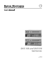
DVS 100 and DVS150
Digital Video Scalers
68-459-01
Printed in USA
Precautions
Safety Instructions • English
This symbol is intended to alert the user of important operating and maintenance
(servicing) instructions in the literature provided with the equipment.
This symbol is intended to alert the user of the presence of uninsulated dangerous
voltage within the product's enclosure that may present a risk of electric shock.
Warning
Power sources • This equipment should be operated only from the power source indicated on the
product. This equipment is intended to be used with a main power system with a grounded
(neutral) conductor. The third (grounding) pin is a safety feature, do not attempt to bypass or
disable it.
Caution
Power disconnection • To remove power from the equipment safely, remove all power cords from
the rear of the equipment, or the desktop power module (if detachable), or from the power
source receptacle (wall plug).
Read Instructions • Read and understand all safety and operating instructions before using the
equipment.
Power cord protection • Power cords should be routed so that they are not likely to be stepped on or
pinched by items placed upon or against them.
Retain Instructions • The safety instructions should be kept for future reference.
Servicing • Refer all servicing to qualified service personnel. There are no user-serviceable parts
inside. To prevent the risk of shock, do not attempt to service this equipment yourself because
opening or removing covers may expose you to dangerous voltage or other hazards.
Follow Warnings • Follow all warnings and instructions marked on the equipment or in the user
information.
Avoid Attachments • Do not use tools or attachments that are not recommended by the equipment
manufacturer because they may be hazardous.
Slots and openings • If the equipment has slots or holes in the enclosure, these are provided to
prevent overheating of sensitive components inside. These openings must never be blocked by
other objects.
Lithium battery • There is a danger of explosion if battery is incorrectly replaced. Replace it only with
the same or equivalent type recommended by the manufacturer. Dispose of used batteries
according to the manufacturer's instructions.
Consignes de Sécurité • Français
Avertissement
Ce symbole sert à avertir l’utilisateur que la documentation fournie avec le matériel
contient des instructions importantes concernant l’exploitation et la maintenance
(réparation).
Alimentations• Ne faire fonctionner ce matériel qu’avec la source d’alimentation indiquée sur
l’appareil. Ce matériel doit être utilisé avec une alimentation principale comportant un fil de
terre (neutre). Le troisième contact (de mise à la terre) constitue un dispositif de sécurité :
n’essayez pas de la contourner ni de la désactiver.
Ce symbole sert à avertir l’utilisateur de la présence dans le boîtier de l’appareil de
tensions dangereuses non isolées posant des risques d’électrocution.
Déconnexion de l’alimentation• Pour mettre le matériel hors tension sans danger, déconnectez tous
les cordons d’alimentation de l’arrière de l’appareil ou du module d’alimentation de bureau (s’il
est amovible) ou encore de la prise secteur.
Attention
Lire les instructions• Prendre connaissance de toutes les consignes de sécurité et d’exploitation avant
d’utiliser le matériel.
Conserver les instructions• Ranger les consignes de sécurité afin de pouvoir les consulter à l’avenir.
Respecter les avertissements • Observer tous les avertissements et consignes marqués sur le matériel ou
présentés dans la documentation utilisateur.
Eviter les pièces de fixation • Ne pas utiliser de pièces de fixation ni d’outils non recommandés par le
fabricant du matériel car cela risquerait de poser certains dangers.
Protection du cordon d’alimentation • Acheminer les cordons d’alimentation de manière à ce que
personne ne risque de marcher dessus et à ce qu’ils ne soient pas écrasés ou pincés par des objets.
Réparation-maintenance • Faire exécuter toutes les interventions de réparation-maintenance par un
technicien qualifié. Aucun des éléments internes ne peut être réparé par l’utilisateur. Afin
d’éviter tout danger d’électrocution, l’utilisateur ne doit pas essayer de procéder lui-même à ces
opérations car l’ouverture ou le retrait des couvercles risquent de l’exposer à de hautes tensions
et autres dangers.
Fentes et orifices • Si le boîtier de l’appareil comporte des fentes ou des orifices, ceux-ci servent à
empêcher les composants internes sensibles de surchauffer. Ces ouvertures ne doivent jamais
être bloquées par des objets.
Lithium Batterie • Il a danger d'explosion s'll y a remplacment incorrect de la batterie. Remplacer
uniquement avec une batterie du meme type ou d'un ype equivalent recommande par le
constructeur. Mettre au reut les batteries usagees conformement aux instructions du fabricant.
Sicherheitsanleitungen • Deutsch
Vorsicht
Dieses Symbol soll dem Benutzer in der im Lieferumfang enthaltenen
Dokumentation besonders wichtige Hinweise zur Bedienung und Wartung
(Instandhaltung) geben.
Stromquellen • Dieses Gerät sollte nur über die auf dem Produkt angegebene Stromquelle betrieben
werden. Dieses Gerät wurde für eine Verwendung mit einer Hauptstromleitung mit einem
geerdeten (neutralen) Leiter konzipiert. Der dritte Kontakt ist für einen Erdanschluß, und stellt
eine Sicherheitsfunktion dar. Diese sollte nicht umgangen oder außer Betrieb gesetzt werden.
Dieses Symbol soll den Benutzer darauf aufmerksam machen, daß im Inneren des
Gehäuses dieses Produktes gefährliche Spannungen, die nicht isoliert sind und
die einen elektrischen Schock verursachen können, herrschen.
Stromunterbrechung • Um das Gerät auf sichere Weise vom Netz zu trennen, sollten Sie alle
Netzkabel aus der Rückseite des Gerätes, aus der externen Stomversorgung (falls dies möglich
ist) oder aus der Wandsteckdose ziehen.
Achtung
Lesen der Anleitungen • Bevor Sie das Gerät zum ersten Mal verwenden, sollten Sie alle Sicherheits-und
Bedienungsanleitungen genau durchlesen und verstehen.
Aufbewahren der Anleitungen • Die Hinweise zur elektrischen Sicherheit des Produktes sollten Sie
aufbewahren, damit Sie im Bedarfsfall darauf zurückgreifen können.
Befolgen der Warnhinweise • Befolgen Sie alle Warnhinweise und Anleitungen auf dem Gerät oder in
der Benutzerdokumentation.
Keine Zusatzgeräte • Verwenden Sie keine Werkzeuge oder Zusatzgeräte, die nicht ausdrücklich vom
Hersteller empfohlen wurden, da diese eine Gefahrenquelle darstellen können.
Instrucciones de seguridad • Español
Schutz des Netzkabels • Netzkabel sollten stets so verlegt werden, daß sie nicht im Weg liegen und
niemand darauf treten kann oder Objekte darauf- oder unmittelbar dagegengestellt werden
können.
Wartung • Alle Wartungsmaßnahmen sollten nur von qualifiziertem Servicepersonal durchgeführt
werden. Die internen Komponenten des Gerätes sind wartungsfrei. Zur Vermeidung eines
elektrischen Schocks versuchen Sie in keinem Fall, dieses Gerät selbst öffnen, da beim Entfernen
der Abdeckungen die Gefahr eines elektrischen Schlags und/oder andere Gefahren bestehen.
Schlitze und Öffnungen • Wenn das Gerät Schlitze oder Löcher im Gehäuse aufweist, dienen diese
zur Vermeidung einer Überhitzung der empfindlichen Teile im Inneren. Diese Öffnungen dürfen
niemals von anderen Objekten blockiert werden.
Litium-Batterie • Explosionsgefahr, falls die Batterie nicht richtig ersetzt wird. Ersetzen Sie
verbrauchte Batterien nur durch den gleichen oder einen vergleichbaren Batterietyp, der auch
vom Hersteller empfohlen wird. Entsorgen Sie verbrauchte Batterien bitte gemäß den
Herstelleranweisungen.
Advertencia
Este símbolo se utiliza para advertir al usuario sobre instrucciones importantes de
operación y mantenimiento (o cambio de partes) que se desean destacar en el
contenido de la documentación suministrada con los equipos.
Alimentación eléctrica • Este equipo debe conectarse únicamente a la fuente/tipo de alimentación
eléctrica indicada en el mismo. La alimentación eléctrica de este equipo debe provenir de un
sistema de distribución general con conductor neutro a tierra. La tercera pata (puesta a tierra) es
una medida de seguridad, no puentearia ni eliminaria.
Este símbolo se utiliza para advertir al usuario sobre la presencia de elementos con
voltaje peligroso sin protección aislante, que puedan encontrarse dentro de la caja
o alojamiento del producto, y que puedan representar riesgo de electrocución.
Desconexión de alimentación eléctrica • Para desconectar con seguridad la acometida de
alimentación eléctrica al equipo, desenchufar todos los cables de alimentación en el panel trasero
del equipo, o desenchufar el módulo de alimentación (si fuera independiente), o desenchufar el
cable del receptáculo de la pared.
Precaucion
Leer las instrucciones • Leer y analizar todas las instrucciones de operación y seguridad, antes de usar
el equipo.
Conservar las instrucciones • Conservar las instrucciones de seguridad para futura consulta.
Obedecer las advertencias • Todas las advertencias e instrucciones marcadas en el equipo o en la
documentación del usuario, deben ser obedecidas.
Evitar el uso de accesorios • No usar herramientas o accesorios que no sean especificamente
recomendados por el fabricante, ya que podrian implicar riesgos.
Protección del cables de alimentación • Los cables de alimentación eléctrica se deben instalar en
lugares donde no sean pisados ni apretados por objetos que se puedan apoyar sobre ellos.
Reparaciones/mantenimiento • Solicitar siempre los servicios técnicos de personal calificado. En el
interior no hay partes a las que el usuario deba acceder. Para evitar riesgo de electrocución, no
intentar personalmente la reparación/mantenimiento de este equipo, ya que al abrir o extraer las
tapas puede quedar expuesto a voltajes peligrosos u otros riesgos.
Ranuras y aberturas • Si el equipo posee ranuras o orificios en su caja/alojamiento, es para evitar el
sobrecalientamiento de componentes internos sensibles. Estas aberturas nunca se deben obstruir
con otros objetos.
Batería de litio • Existe riesgo de explosión si esta batería se coloca en la posición incorrecta. Cambiar
esta batería únicamente con el mismo tipo (o su equivalente) recomendado por el fabricante.
Desachar las baterías usadas siguiendo las instrucciones del fabricante.
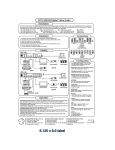
Quick Start — DVS 100 and DVS 150
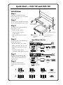
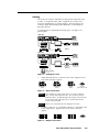
Installation
Step 1
Install the four rubber feet on the
bottom of the scaler (1A), or mount the
scaler in a rack (1B).
Step 2
Turn off power to the input and output
devices, and unplug their power cords.
Step 3
False front panel
uses 2 front holes
Attach the scaler to the input devices.
Input options (3) are:
INPU
T
1
Composite video (input 1)
2
3
CO
LO
R
TIN
T
BR
IT
CO
NT
RA
ST
H SH
IFT
Component video (input 2)
V SH
IFT
(2) 4-40 x 1/8" screws
RA
TE
DIG
ITA
DV
L VID S
EO 10
SC 0
AL
ER
S-video (input 3)
1A
RGB pass-thru (input 4; DVS 150
only)
Step 4
or
Rubber feet
bottom side
(4 plcs)
1B
Use 2 mounting holes on
opposite corners
Input/Output Devices
Attach the scaler to the output devices.
DVS 100
Output options (4) are:
100-240V
0.1A
INPUTS
VID
OUTPUTS
B-Y
1
S-VIDEO
RGsB (connected to R, G, and B)
RGB OUT
Y
R-Y
2
50/60 Hz
3
R
G
B
H
V
S
REMOTE
RS-232 Control
RGBS (connected to R, G, B, and S)
or
RGBHV (connected to R, G, B, H,
and V)
or
DVD Player
HDTV Plasma
DLP Projector
CRT Projector
Laserdisc Player
VGA/XGA/SVGA/SXGA
(connected to RGB output connector)
OUTPUT
DSS Receiver
INPUT
DVS 150
Step 5
100-240 VAC .3A MAX
INPUTS
VIDEO
OUTPUTS
B-Y
1
Y
R-Y
Plug the scaler, input device, and
output device into a grounded AC
source, and turn on the input and
output devices.
2
50/60 Hz
REMOTE
R
G
B
H
V
S
RGB
PASS-THRU
S-VIDEO
3
RGB
4
RS-232 Control
DLP Projector
DVD Player
or
or
Laserdisc Player
Step 6
HDTV Plasma
VID
Laptop
Computer
VID
INPUT
B-Y
1
B-Y
1
Y
R-Y
2
1
Y
R-Y
2
3
Composite Video
(Input 1)
Y
R-Y
2
3
Component Video
(Input 2)
3
S-video
(Input 3)
R
G
B
R
G
B
R
G
B
H
V
S
H
V
S
H
V
S
RGsB
CRT Projector
OUTPUT
VID
B-Y
3
LCD Projector
DSS Receiver
Use the LCD menu screens to
configure the scaler (see the next
page).
4
DLP Projector
RGBS
RGBHV
RGB
Pass-Thru
(Input 4; DVS 150 only)
RGB Output
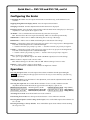
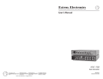
Quick Start — DVS 100 and DVS 150, cont’d
Configuring the Scaler
Configuring the scaler: Press the input and rate buttons simultaneously, and hold them for two
seconds.
Stepping through the LCD display menus: Press the input selection button.
Changing a selection: Turn the adjustment knob while the menu is displayed.
Exiting the menus: Press the input selection button while the Detail menu is displayed, or don’t press
any buttons or turn any knobs for eight seconds.
AUTOSW — Choose whether the DVS automatically selects the active input.
On: The DVS selects the active input automatically. Off: You select the input manually.
TOPBLANK — Add or remove additional blanking lines at the top of the image.
BOTBLANK — Add or remove additional blanking lines at the bottom of the image.
H-SYNC — Change the polarity of the horizontal sync signal to allow any projector to distinguish the
DVS 100 or DVS 150 input from a standard RGB input.
+: Sets the horizontal sync polarity to positive. -: Sets the horizontal sync polarity to negative.
V-SYNC — Change the polarity of the vertical sync signal to allow any projector to distinguish the
DVS 100 or DVS 150 input from a standard RGB input.
+: Sets the vertical sync polarity to positive. -: Sets the vertical sync polarity to negative.
SOG — Set the sync output format.
Yes: Sync on green (RGsB) output. No: RGBS or RGBHV output (based on unit cabling).
STILL — Enhance output for still or motion video.
On: Enhanced image for still video and text. Off: Enhanced image for motion video.
DETAIL — Apply a filter to improve image detail.
1: Low level of detail. 2: Medium level of detail. 3: High level of detail.
Operation
Choosing the input source: Press the input selection button until the desired input LED lights.
If input 4 (RGB pass-through) of the DVS 150 is selected, you cannot make any of the following
adjustments.
Adjusting the image: Press the button for the adjustment, and rotate the adjustment knob until the
desired result is achieved.
Choosing the output rate: Press and hold the rate button for two seconds, and then rotate the
adjustment knob until the desired rate appears in the LCD display. Options are:
640x480 (VGA), 60/75 Hz 848x480 (plasma), 60 Hz
1280x768 (plasma), 56 Hz 480p (HDTV)
800x600 (SVGA), 60/75 Hz 852x480 (plasma), 60/75 Hz 1280x1024 (SXGA), 60 Hz 720p (HDTV)
832x624 (Mac), 60/75 Hz
1024x768 (XGA), 60/75 Hz
1360x765 (plasma), 60 Hz 1080p (HDTV)
Activating freeze mode: Issue the RS-232 freeze mode command.
Deactivating freeze mode: Press the input selection button or issue an RS-232 command.
Restoring default picture control settings (active input): Press and hold the input selection button for
two seconds.
Restoring all settings to factory defaults: Press and hold the input selection button while attaching
the AC power cord.
Table of Contents
Chapter 1 • Introduction .......................................................................................... 1-1
About the Scaler .................................................................................................... 1-2
Features ..................................................................................................................... 1-2
Chapter 2 • Installation ............................................................................................. 2-1
Rear Panel Features .............................................................................................. 2-2
Installation ............................................................................................................... 2-3
Overview .............................................................................................................. 2-3
Mounting the scaler ............................................................................................ 2-3
Installing the rubber feet .................................................................................... 2-4
Cabling ................................................................................................................. 2-5
Front Panel Features ............................................................................................. 2-6
Configuring the Scaler ......................................................................................... 2-6
Configuration settings ........................................................................................ 2-7
Chapter 3 • Operation ................................................................................................ 3-1
Front Panel Operations ........................................................................................ 3-2
Default screens .................................................................................................... 3-2
Choosing the input source .................................................................................. 3-2
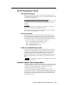
Adjusting an image ............................................................................................. 3-2
Choosing the output rate ................................................................................... 3-3
Freeze mode ........................................................................................................ 3-4
Executive mode ................................................................................................... 3-4
Resetting the scaler ............................................................................................. 3-4
Channel reset .................................................................................................. 3-4
System reset .................................................................................................... 3-5
Chapter 4 • Serial Communication ..................................................................... 4-1
RS-232 Programmer’s Guide .............................................................................. 4-3
DVS initiated messages ....................................................................................... 4-3
DVS error response .............................................................................................. 4-3
Using the command/response table ................................................................... 4-3
Command/response table ................................................................................... 4-4
Remote Contact Closure Operation ................................................................ 4-3
Control Software for Windows ........................................................................ 4-5
Installing the Software ........................................................................................ 4-5
Using the Software .............................................................................................. 4-6
DVS 100 and DVS 150 Table of Contents
1-i
Table of Contents, cont’d
Chapter 5 • Troubleshooting .................................................................................. 5-1
Operating Problems .............................................................................................. 5-2
Appendix A • Specifications .................................................................................. A-1
Appendix B • Reference Information ................................................................ B-1
Part Numbers .......................................................................................................... B-2
DVS 100 and DVS 150 part numbers .................................................................. B-2
Related part numbers ......................................................................................... B-2
BNC cables ........................................................................................................... B-2
Glossary ..................................................................................................................... B-3
68-459-01 C
Printed in the USA
04 00
ii
DVS 100 and DVS 150 Table of Contents
DVS 100 and DVS 150
1
Chapter One
Introduction
About the Scaler
Features
Introduction
Introduction, cont’d
About the Scaler
Each DVS 100 and DVS 150 digital video scaler allows analog video
signals (composite video, S-video, and component video) to be
displayed on a device with a fixed resolution and aspect ratio, such as an
LCD (liquid crystal display) projector, DLP (digital light processing)
projector, or plasma display.
DVS 150 includes a 15-pin HD RGB pass-through connector for RGB
input. Video signals coming into the scaler from this connector are not
scaled. Instead, they are passed directly to the ouputs.
Features
• Autosave — Automatically stores adjustments and uses the control
settings associated with the selected input.
• Autoswitch mode — Automatically selects the active input device. If
more than one input device is on, the device with the highest
video quality is selected.
• Blanking — Allows noise or unwanted information, such as tape head
switching and closed captioning, to be eliminated from the top
and bottom of the display.
• Dual output connectors — Allow you to connect and run two output
devices simultaneously.
• Executive mode — Locks out all front-panel image adjustment
functions except input selection. When executive mode is active,
all image adjustments are available through RS-232 commands.
• Freeze mode — Locks the output display to the current image.
• Inputs — Includes three BNC connectors for component video, one
BNC connector for composite video, and one 4-pin mini-DIN
connector for S-video. The DVS 150 also includes one 15-pin HD
connector for RGB pass-through input.
• Multiple control methods — Allow you to make adjustments by
pressing a button on the front panel, choosing options from a
menu, sending an RS-232 command from a computer, or using a
remote contact closure control.
• Outputs — Outputs video as RGB, RGsB, RGBS, and RGBHV. BNC
connectors and a 15-pin HD connector are provided.
1-2
DVS 100 and DVS 150 Introduction
• Output resolutions — Supports the following output resolutions:
•
640 x 480 (VGA) at 60 or 75 Hz (Hertz)
•
800 x 600 (SVGA) at 60 or 75 Hz
•
832 x 624 (Macintosh) at 60 or 75 Hz
•
848 x 480 (plasma) at 60 Hz
•
852 x 480 (plasma) at 60 or 75 Hz
•
1024 x 768 (XGA) at 60 or 75 Hz
•
1280 x 768 (plasma) at 56 Hz
•
1280 x 1024 (SXGA) at 60 Hz
•
1360 x 765 (plasma) at 60 Hz
•
480p (HDTV)
•
720p (HDTV)
•
1080p (HDTV)
• Power supply — Includes an internal, 100-240VAC, 50/60 Hz, autoswitchable power supply.
• Precise image processing — Provides the latest in motion compensation,
which produces motion images that are free of “jaggies”; a threeline adaptive comb filter, which eliminates chroma crawl; and a quad
standard decoder, which ensures compatibility with NTSC (National
Television Standards Committee) 3.58, NTSC 4.43, SECAM
(sequential couleur avec mémoire), and PAL (phase alternate line)
video standards.
• Software-based configuration — Allows you to configure the scaler
through menu controls, simplifying installation.
• Switchable sync polarities — Allow you to manually set the
horizontal and vertical sync polarities, to allow the output device
to store DVS input as a unique input.
DVS 100 and DVS 150 Introduction
1-3
Introduction, cont’d
1-4
DVS 100 and DVS 150 Introduction
DVS 100 and DVS 150
2
Chapter Two
Installation
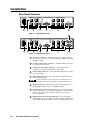
Rear Panel Features
Installation
Front Panel Features
Configuring the Scaler
Installation
Installation, cont’d
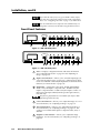
Rear Panel Features
100-240V
0.3A
INPUTS
VIDEO
OUTPUTS
B-Y
1
S-VIDEO
R-Y
2
50/60 Hz
2
1
RGB
Y
3
4
3
R
G
B
H
V
S
5
REMOTE
7
6
Figure 1 — DVS 100 rear panel
7
100-240V
0.3A
INPUTS
VIDEO
OUTPUTS
B-Y
REMOTE
R
G
B
H
V
S
1
R-Y
S-VIDEO
2
50/60 Hz
1
Y
2
3
RGB
3
4
RGB
4
8
6
5
Figure 2 — DVS 150 rear panel
2-2
1
AC power connector — Standard AC power connector attaches
the scaler to any power source from 100VAC to 240VAC, operating
at 50 Hz or 60 Hz.
2
Composite video input connector — One BNC female connector
for composite video input.
3
Component video input connectors — Three BNC female
connectors for component (R-Y, B-Y, Y) video input.
4
S-video input connector — One 4-pin mini-DIN female connector
for S-video input.
5
RGB output connector — One 15-pin HD female RGB connector
for the output projector.
You can install and run two output devices simultaneously, one
using BNC connectors, and the other using the RGB connector.
6
Output connectors — BNC female connectors for RGsB (sync on
green), RGBS (composite sync), or RGBHV output.
7
RS-232/contact closure remote connector — One 9-pin D female
connector that allows you to attach a computer or another device,
such as a keypad or other contact closure device, for remote
control of the scaler.
8
RGB pass-thru connector (DVS 150 only) — One 15-pin HD
female RGB connector for input. The signal from the input device
is passed through to the output connectors without being scaled.
DVS 100 and DVS 150 Installation
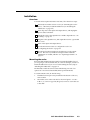
Installation
Overview
To install and set up the DVS 100 or DVS 150, follow these basic steps:
1
If desired, mount the scaler in a rack (see “Mounting the scaler”
below). Otherwise, install the rubber feet (see “Installing the
rubber feet” on page 2-4).
2
Turn off power to the input and output devices, and unplug the
power cables from them.
3
Attach the scaler to the input devices and the output devices. See
“Cabling” on page 2-5.
4
Plug the scaler, input devices, and output devices into a grounded
AC source.
5
Turn on the input and output devices.
6
Use the LCD menu screens to configure the scaler. See
“Configuring the Scaler” on page 2-7.
7
The image from the input device should appear on the output
device. If it does not, double check steps 3 and 4 and make
adjustments as needed, and then see “Operating Problems” on
page 5-2.
Mounting the scaler
Each DVS 100 and DVS 150 ships with four uninstalled rubber feet. If
you are going to rack mount the unit, do so before cabling it, and do not
install the rubber feet. If you are not rack mounting the scaler, skip to
“Installing the rubber feet” on page 2-4.
The DVS 100 or DVS 150 can be rack mounted using one side of an
optional 19” 1U Universal Rack Shelf (Extron part # 60-190-01).
To rack mount the scaler, do the following:
1.
If rubber feet were previously installed on the bottom of the case,
remove them.
2.
Mount the scaler on the rack shelf as shown in figure 3. Use two
4-40 x 1/8” screws in opposite (diagonal) corners to secure the case
to the shelf.
DVS 100 and DVS 150 Installation
2-3
Installation, cont’d
False front panel
uses 2 front holes
INPU
T
1
2
3
CO
LO
R
(2) 4-40 x 1/8" Screws
TIN
T
BR
IT
CO
NT
RA
ST
H SH
IFT
V SH
IFT
RA
TE
DIGI
TA
D
L VI VS
DE
O 100
SC
AL
ER
Use 2 mounting holes on
opposite corners
Figure 3 — Mounting the scaler
Installing the rubber feet
The scaler ships with four uninstalled rubber feet. Install the rubber feet
only if you are not rack mounting the scaler. To install the rubber feet,
do the following:
1.
Turn the scaler upside down and place it on a flat surface.
2.
Remove the protective backing from a rubber foot.
3.
Place the rubber foot on one corner of the scaler as shown in figure
4, and press it into place.
Position the rubber foot carefully before pressing it into place. It is
difficult to move the foot after it is in place.
INPU
T
1
2
3
CO
LO
R
TIN
T
BR
IT
CO
NT
RA
ST
H SH
IFT
V SH
IFT
RA
TE
Rubber Feet
Bottom Side (4 Plcs)
DIG
ITA
DV
L VID S
EO 10
SC 0
AL
ER
Figure 4 — Installing the rubber feet
2-4
4.
Repeat steps 2 and 3 to install a rubber foot on each of the
remaining corners of the scaler.
5.
Turn the scaler right side up and place it in the desired location.
DVS 100 and DVS 150 Installation
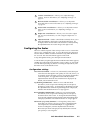
Cabling
The scaler can connect to input devices that produce composite video,
S-video, or component video, and to output devices, such as LCD
projectors, DLP displays, or plasma displays. The DVS 150 can also
connect to input devices that produce RGB video via the RGB passthrough connector.
To cable the scaler, complete the following steps. Use figure 5 as a
general guide.
DVS 100
100-240V
0.1A
INPUTS
VID
OUTPUTS
B-Y
1
S-VIDEO
RGB OUT
Y
R-Y
2
50/60 Hz
3
R
G
B
H
V
S
REMOTE
RS-232 Control
or
or
DVD Player
HDTV Plasma
DLP Projector
CRT Projector
Laserdisc Player
OUTPUT
DSS Receiver
DLP Projector
INPUT
DVS 150
100-240 VAC .3A MAX
INPUTS
VIDEO
OUTPUTS
B-Y
1
Y
R-Y
2
50/60 Hz
REMOTE
R
G
B
H
V
S
RGB
PASS-THRU
S-VIDEO
3
RGB
4
RS-232 Control
DLP Projector
DVD Player
or
or
Laserdisc Player
HDTV Plasma
LCD Projector
DSS Receiver
Laptop
Computer
CRT Projector
OUTPUT
INPUT
Figure 5 — Cabling the scaler
1.
Attach the input device (or devices) to the scaler. Figure 6 shows
each of the connection options.
VID
VID
VID
B-Y
B-Y
1
B-Y
1
R-Y
Y
2
1
R-Y
Y
2
3
Composite Video
(Input 1)
R-Y
Y
2
3
Component Video
(Input 2)
RGB
Pass-Thru
(Input 4; DVS 150 only)
3
S-video
(Input 3)
Figure 6 — Input connections
You can attach up to three input devices, one each of composite
video, S-video, and component video. You can also connect an
RGB input device, for pass-through to the output, to the DVS 150.
You can select among the input sources via the input selection
switch on the front panel.
If there is no video input, the LCD displays “No Source”.
2.
Use BNC connectors or a 15-pin HD connector to connect the scaler
to the output device. Figure 7 shows each of the connection
options.
R
G
B
R
G
B
R
G
B
H
V
S
H
V
S
H
V
S
RGsB
RGBS
RGB Output
RGBHV
Figure 7 — Output connections
DVS 100 and DVS 150 Installation
2-5
Installation, cont’d
If you cable the scaler for sync on green (RGsB or SOG) output,
you must also configure the scaler for SOG via the configuration
menu. See “Configuring the Scaler” on page 2-7 for instructions.
You can install and run two output devices simultaneously, one
using BNC connectors, and the other using the RGB connector.
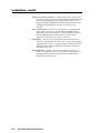
Front Panel Features
INPUT
1
2
3
COLOR
TINT
BRIGHT
CONT
H SHIFT
V SHIFT
RATE
DVS 100
DIGITAL VIDEO SCALER
1
3
2
4
5
6
7
8
9
10
11
Figure 8 — DVS 100 front panel
INPUT
1
2
3
4
COLOR
TINT
BRIGHT
CONT
H SHIFT
V SHIFT
RATE
DVS 150
DIGITAL VIDEO SCALER
1
2
3
4
5
6
7
8
9
10
11
Figure 9 — DVS 150 front panel
2-6
1
LCD — Displays configuration menus and status information.
See “Configuring the Scaler” on page 2-7 and “Adjusting an
image” on page 3-2.
2
Input selection button — Allows you to select the input type (see
“Choosing the input source” on page 3-2). If the image has been
frozen via an RS-232 command, the input button cancels the freeze
function (see “Freeze mode” on page 3-4).
3
Input LEDs — Display the active input. If LED (light emitting
diode) 1 is lit, the input is composite video. If LED 2 is lit, the
input is component video. If LED 3 is lit, the input is S-video. If
LED 4 is lit , the input is RGB (from the pass-though connector;
DVS 150 only).
The following adjustments are not available if the input is RGB
pass-through (DVS 150 only).
4
Color control button — Allows you to adjust the image color. For
more information, see “Adjusting an image” on page 3-2.
5
Tint control button — Allows you to adjust the image tint. For
more information, see “Adjusting an image” on page 3-2. This
control is not available if the input is component video, PAL, or
SECAM.
6
Brightness control button — Allows you to adjust the image
brightness. For more information, see “Adjusting an image” on
page 3-2.
DVS 100 and DVS 150 Installation
7
Contrast control button — Allows you to adjust the image
contrast. For more information, see “Adjusting an image” on
page 3-2.
8
Horizontal shift control button — Allows you to adjust the
horizontal shift. For more information, see “Adjusting an image”
on page 3-2.
9
Vertical shift control button — Allows you to adjust the vertical
shift. For more information, see “Adjusting an image” on
page 3-2.
10
Output rate control button — Allows you to choose the output
rate. For more information, see “Choosing the output rate” on
page 3-3.
11
Adjustment knob — With a control button selected, allows you to
make adjustments to the feature controlled by the button. For
example, if the horizontal shift control button is selected, turning
the adjustment knob moves the image to the right or left.
Configuring the Scaler
The LCD on the front panel of the scaler provides access to a menu that
allows you to configure the scaler. To access the menu, press the input
selection button and the rate button simultaneously, and hold them for
two seconds. The Autoswitch menu appears in the LCD.
To step through the menus, press the input selection button.
To exit the menu, step through the menus until the Detail menu appears,
and then press the input selection button one more time. Or, wait eight
seconds without pressing any buttons or turning the adjust knob, and
the menu reverts to the default screens.
Configuration settings
Autoswitch (AUTOSW) — If set to On, automatically selects the input
source that uses the highest video quality. If set to Off, allows you
to manually specify the input source by pressing the input button
on the front panel. To toggle between On and Off, turn the
adjustment knob while the Autoswitch menu is displayed. By
default, autoswitch mode is Off.
Top blanking (TOPBLANK) — Removes noise and unwanted
information, such as tape head switching and closed captions,
from the top of the screen. To change the top blanking level, turn
the adjustment knob while the Top blanking menu is displayed,
until the unwanted information no longer appears.
Bottom blanking (BOTBLANK) — Removes noise and unwanted
information, such as tape head switching and closed captions,
from the bottom of the screen. To change the bottom blanking
level, turn the adjustment knob while the Bottom blanking menu
is displayed, until the unwanted information no longer appears.
Horizontal sync polarity (H-SYNC) — Changes the polarity of the
horizontal sync signal to allow any projector to distinguish the
scaler input from a standard RGB input. To toggle between
Positive and Negative, turn the adjustment knob while the
Horizontal sync menu is displayed. By default, the horizontal
sync polarity is set to Negative.
DVS 100 and DVS 150 Installation
2-7
Installation, cont’d
Vertical sync polarity (V-SYNC) — Changes the polarity of the vertical
sync signal to allow any projector to distinguish the DVS 100 input
from a standard RGB input. To toggle between Positive and
Negative, turn the adjustment knob while the Vertical sync menu
is displayed. By default, the vertical sync polarity is set to
Negative.
Sync on green (SOG) — If set to Yes, provides sync on green (RGsB or
SOG) output. If set to No, provides RGBS or RGBHV output,
depending on the attached cables. To toggle between Yes and No,
turn the adjustment knob while the Sync on green menu is
displayed. By default, Sync on green is set to No.
Still (STILL) — If set to On, provides enhanced resolution for easier
viewing of text and other motionless video. If set to Off, provides
optimized motion video. To toggle between On and Off, turn the
adjustment knob while the Still menu is displayed. By default,
still mode is set to Off.
Detail (DETAIL) — Applies a filter to improve the image’s level of
detail. To switch between 1 (low), 2 (medium), and 3 (high), turn
the adjustment knob while the Detail menu is displayed. By
default, detail mode is set to 3.
2-8
DVS 100 and DVS 150 Installation
DVS 100 and DVS 150
3
Chapter Three
Operation
Front Panel Operations
Operation
Operation, cont’d
Front Panel Operations
The front panel includes an LCD screen that displays the current status
of the scaler and the scan rate of the current video input signal. You can
also use controls on the front panel to control the image display.
Diagrams of the front panels are shown on page 2-6.
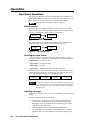
Default screens
By default, the LCD toggles between two screens every four seconds.
One screen displays the product name, and the other shows the output
resolution and frequency (figure 10 shows an example).
EXTRON
DVS 100
1280 X
1024 @60
Figure 10 — Default screens
If no input signal is present, the LCD backlight turns off and the LCD
toggles between screens similar to those shown in figure 11.
EXTRON
DVS 100
No
Source
Figure 11 — No signal present
Choosing the input source
To choose an input source, press the input selection button to toggle
through the inputs. The LED corresponding to the selected input lights:
• Input LED 1 — Composite video
• Input LED 2 — Component video
• Input LED 3 — S-video
• Input LED 4 — RGB pass-through video (DVS 150 only)
When the button is released, the input changes and the LCD shows the
current input and signal type (see figure 12). The message appears for
8 seconds, and then changes back to the default screens.
INPUT 1
CMPOSITE
INPUT 2
COMPNENT
INPUT 3
S-VIDEO
INPUT 4
RGB
Figure 12 — Current input screens
If an RS-232 command was issued to activate the freeze function, to
change the input source you must press the input selection button
twice. The first press unfreezes the image, and the second changes
the input source.
Adjusting an image
The front panel controls allow you to make adjustments to the displayed
image.
To make an adjustment, do the following:
3-2
1.
Push the control button that corresponds to the adjustment you
want to make. The LED above the pressed button lights, and,
depending on the selected button, the LCD displays the current
level value for the adjustment.
2.
Turn the adjustment knob until the desired adjustment is
accomplished. The LCD returns to the default screens, and the
adjusted value is saved for future use by the active input, if you
DVS 100 and DVS 150 Operation
press the same button again or if you stop turning the knob for
eight seconds.
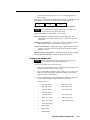
If an image control reaches its minimum, maximum, or default level, the
LCD displays a screen similar to the screens shown in figure 13.
COLOR
Min
COLOR
Default
COLOR
Max
Figure 13 — Minimum, maximum, and default value screens
If input 4 (RGB pass-through) of the DVS 150 is selected, you
cannot adjust the image through the scaler.
Color control button — Adjusts the color intensity.
Tint control button — Adjusts the amount of tint displayed. This
adjustment is not available if the input is component video, PAL,
or SECAM.
Brightness control button — Adjusts the amount or intensity of video
light produced on the screen, without regard to color.
Contrast control button — Adjusts the range of light and dark values in
a picture, or the ratio between the maximum and the minimum
brightness values.
Horizontal shift control button — Shifts the image to the left and right.
Vertical shift control button — Shifts the image up and down.
Choosing the output rate
If input 4 (RGB pass-through) of the DVS 150 is selected, you
cannot change the output rate through the scaler.
To choose the output rate, do the following:
1.
Refer to the documentation that accompanied the display device to
determine its native mode (or sweet spot).
2.
Press and hold the rate button on the scaler for two seconds. The
LED above the button lights, and the LCD displays the current
output resolution and frequency.
3.
Turn the adjustment knob until the desired output rate appears in
the LCD and the image is displayed at the correct rate.
Available rates are:
•
640 x 480, 60 Hz
•
640 x 480, 75 Hz
•
800 x 600, 60 Hz
•
800 x 600, 75 Hz
•
832 x 624, 60 Hz
•
832 x 624, 75 Hz
•
848 x 480, 60 Hz
•
852 x 480, 60 Hz
•
852 x 480, 75 Hz
•
1024 x 768, 60 Hz
•
1024 x 768, 75 Hz
•
1280 x 768, 56 Hz
•
1280 x 1024, 60 Hz
•
1360 x 765, 60 Hz
•
HDTV 480p
•
HDTV 720p
•
HDTV 1080p
DVS 100 and DVS 150 Operation
3-3
Operation, cont’d
Freeze mode
Freeze mode locks the output display to the current image. Freeze mode
can be activated only by issuing an RS-232 command
IMAGE
(see chapter 4 for more information). If freeze mode
FROZEN
is activated, the LCD screen displays the message
displayed at the left.
If input 4 (RGB pass-through) of the DVS 150 is selected, you
cannot activate freeze mode.
You can deactivate freeze mode in the following ways:
• By issuing another RS-232 command
• By pressing the input selection button
• Automatically, if the scaler is in autoswitch mode and the input source
changes.
Executive mode
Executive mode limits the number of operations available from the front
panel. This is useful for situations in which many end users operate the
scaler, and you want to prevent them from changing the adjustments
you have made.
To enable executive mode, press the horizontal shift and vertical shift
control buttons simultaneously for two seconds. The
X-MODE
ENABLED
LCD displays the message at the left for eight
seconds, and then changes back to the default
screens.
When executive mode is enabled, the only front panel button that can be
used is the input selection button. If any other button is pressed, the
LCD displays the same message for eight seconds, then changes back to
the default screens.
To disable executive mode, press the horizontal shift and vertical shift
control buttons simultaneously for two seconds. The
X-MODE
LCD displays the message at the left for eight
DISABLED
seconds, then changes back to the default screens.
Resetting the scaler
You can perform two types of reset:
• Channel reset restores the factory default picture control settings (color,
tint, brightness, contrast, horizontal shift, and vertical shift) for
only the currently selected input.
If input 4 (RGB pass-through) of the DVS 150 is selected, you
cannot perform a channel reset.
• System reset restores all factory default settings, including all picture
controls for all inputs, the output rate, and all configuration
options available from the LCD menu.
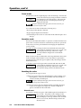
Channel reset
To perform a channel reset, press and hold the input selection button for
two seconds. The picture control settings for the
INPUT 1
active input are reset to their factory default settings.
RESET
The LCD displays a message similar to the one at the
left for four seconds, and then changes back to the
default screens.
3-4
DVS 100 and DVS 150 Operation
System reset
To perform a system reset, press and hold the input selection button
while attaching the AC power cord. The picture
SYSTEM
control settings for all input sources, the output rates,
RESET
and the configuration options are reset to their factory
default settings. The LCD displays the message at
the left for four seconds, and then changes back to the
default screens.
DVS 100 and DVS 150 Operation
3-5
Operation, cont’d
3-6
DVS 100 and DVS 150 Operation
DVS 100 and DVS 150
4
Chapter Four
Serial Communication
RS-232 Programmer’s Guide
Remote Contact Closure Operation
Control Software for Windows
Serial
Communication
Serial Communication,
cont’d
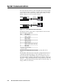
The scaler’s RS-232 connector can be connected to the serial port output
of a host device such as a computer or control system. This connection
makes software control of the scaler possible. Figure 14 shows a scaler
RS-232 connection to a host serial port connector.
OUTPUTS
R
G
H
V
B
REMOTE
RS-232
Control Cable
S
DVS 100
OUTPUTS
REMOTE
R
G
B
H
V
S
Computer Control
RS-232
Control Cable
RGB
Computer Control
DVS 150
Figure 14 — Scaler RS-232 to host connection
The RS-232 connector on the scaler is a 9-pin D female connector with
the following pin assignments:
Pin
Description
1
Input 1 select*
2
Transmit data
3
Receive data
4
Input 2 select*
5
Signal ground
6
Input 3 select*
7
Input 4 select* (DVS 150 only)
8
Not used
9
Not used
* Used for remote contact
closure control
The protocol is 9600 baud, 8-bit, 1 stop bit, no parity, and no flow
control.
The DVS 100 or DVS 150 scaler accepts SIS™ (Simple Instruction Set™)
commands through the RS-232 port. SIS commands consist of one or
more characters per command field. They do not require any special
characters to begin or end the command character sequence. Each scaler
response to an SIS command ends with a carriage return and a line feed
(CR/LF = ), which signals the end of the response character string. (A
string is one or more characters.)
4-2
DVS 100 and DVS 150 Serial Communication
RS-232 Programmer’s Guide
DVS initiated messages
When a local event occurs, such as a front panel operation, the scaler
responds by sending a message to the host. The DVS-initiated messages
are listed below (underlined).
(C) Copyright 1999, Extron Electronics, DVS xxx, Vx.x
The copyright message is initiated by the scaler when it is first powered
on. DVS xxx is the scaler model, and Vx.xx is the firmware version
number.
Reconfig
The Reconfig message is initiated by the scaler when a new input is
selected or when any image adjustment is made.
The scaler does not expect a response from the host, but, for example,
the host program might request a new status.
DVS error response
When the scaler receives an SIS command and determines that it is
valid, it performs the command and sends a response back to the host
device. If the scaler is unable to perform the command because the
command is invalid or contains invalid parameters, the scaler returns an
error response to the host. The error response codes are:
E01 — Invalid input channel number (too large)
E09 — Invalid function number (too large)
E10 — Invalid command
E13 — Invalid value (out of range)
Using the command/response table
The command/response table is shown on the next page. Lower case
characters are acceptable in the command field only where indicated.
Symbols are used throughout the table to represent variables in the
command/response fields. Symbol definitions are shown at the
beginning of the table, as is an ASCII-to-hexadecimal (HEX) conversion
table. Command and response examples are shown throughout the
table.
Screen adjustment commands are not available if input 4 is selected
(DVS 150 only).
Remote Contact Closure Operation
The RS-232 connector provides a way to control the scaler from a remote
contact closure device. This is made possible by using pins that are not
normally used by the RS-232 interface. The contact closure pin
assignments are shown in the table on page 4-2.
To select a different input number through the RS-232 connector,
momentarily short the pin for the desired input number (#) to the signal
ground (pin 5). To force one of the inputs to be selected continuously,
leave the short to signal ground in place. This will override any front
panel input selection.
DVS 100 and DVS 150 Serial Communication
4-3
Serial Communication, cont’d
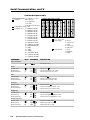
Command/response table
Symbol definitions: = CR/LF, • = space
= Inputs =
1 = Composite
2 = Component
3 = S-video
4 = RGB (DVS 150 only)
= Adjustment range 1-127
= Output rate = 1 = 640x480 @ 60 Hz
2 = 640x480 @ 75 Hz
3 = 800x600 @ 60 Hz
4 = 800x600 @ 75 Hz
5 = 832x624 @ 60 Hz
6 = 832x624 @ 75 Hz
7 = 852x480 @ 60 Hz
8 = 852x480 @ 75 Hz
9 = 1024x768 @ 60 Hz
10 = 1024x768 @ 75 Hz
11 = 1280x1024 @ 60 Hz
12 = 480p
13 = 720p
14 = 1080p
15 = 848x480 @ 60 Hz
16 = 1280x768 @ 56 Hz
17 = 1360x765 @ 60 Hz
COMMAND
Input selection
ASCII
ASCII to HEX Conversion Table
•
= 1 = on, 0 = off
= Input type
0 = None
1 = NTSC 3.58
2 = PAL
3 = NTSC 4.43
4 = SECAM
= Detail level
1 = Low
2 = Medium
3 = High
RESPONSE
DESCRIPTION
!
C
Sets input source
C
Col
Col
Col
Selects color
Selects next higher color value
Selects next lower color value
T
Tin
Tin
Tin
Selects tint
Selects next higher tint value
Selects next lower tint value
^
Con
Con
Con
Selects contrast
Selects next higher contrast value
Selects next lower contrast value
Y
Brt
Brt
Brt
Selects brightness
Selects next higher brightness value
Selects next lower brightness value
H
Hph
Hph+
Hph–
Selects horizontal shift
Shift image right one step
Shift image left one step
Color
Specific value
Increment up
Increment down
{C
}C
Tint
Specific value
Increment up
Increment down
{T
}T
Contrast
Specific value
Increment up
Increment down
{^
}^
Brightness
Specific value
Increment up
Increment down
{Y
}Y
Horizontal shift
Specific value
Increment up
Increment down
4-4
{H
}H
DVS 100 and DVS 150 Serial Communication
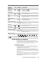
COMMAND
Vertical shift
Specific value
Increment up
Increment down
ASCII
RESPONSE
DESCRIPTION
/
Vph
Vph+
Vph–
Selects vertical shift
Shift image up one step
Shift image down one step
=
Rte
Set the video output rate
F
f
Frz 1
Frz Ø
Set freeze mode to On (freeze current displayed image)
Set freeze mode to Off
X
x
Exe 1
Exe Ø
Set executive mode to On
Set executive mode to Off
{/
}/
Set output rate
Freeze
Enable
Disable
Executive mode
Enable
Disable
Query software version
q
Q
(Same as Q below)
Example response: Ver 1.23
Ver x.xx
Still mode
#
Stl
Sets still mode On or Off
D
Det
Sets detail mode to level 1 (low), 2, or 3 (high)
Detail mode
Request part number
n
N
(Same as N below)
Displays the Extron part number: 60-304-01 is DVS 100,
N6Ø-3Ø4-Ø1
and 60-317-01 is DVS 150
Request information*
i
I
(Same as I below)
C •Col •Tin •Con •Brt
•Exe •Typ •Stl •Det
•Hph
•Vph
•Rte
•Frz
* Typ
displays the type of input video signal as automatically sensed by the scaler. You cannot change
this entry.
Control Software for Windows
The Signal Enhancement Products Control Program (part # 29-017-01),
which is used by the scalers, is compatible with Windows 3.1, 3.11, 95/
98, and NT. It provides remote control of scaler settings. For DVS 100,
use version 3.1 or later; for DVS 150, use version 3.2 or later.
Installing the software
The program is contained on a single 3.5-inch diskette, and it can run
from the floppy drive. However, it is usually more convenient to load
and run the program from the hard drive.
To install the software from the floppy disk onto the hard drive, run
SETUP.EXE from the floppy disk, and follow the instructions that appear
on the screen. The program occupies approximately 1 MB (megabyte) of
hard-drive space.
By default, the Windows installation creates a C:\S_ENHANC directory,
and it places two icons (Signal Enhancement Products Control Pgm and
Signal Enhancement Products Help) into a group or folder named
“Extron Electronics”.
DVS 100 and DVS 150 Serial Communication
4-5
Serial Communication, cont’d
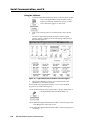
Using the software
1.
To run the Signal Enhancement Products Control Program, doubleclick on the Signal Enhancement Products Control
Pgm icon in the Extron Electronics group or folder.
The Comm menu appears on the screen.
2.
Click on the comm port that is connected to the scaler’s RS-232
port.
The Extron Signal Enhancement Products Control Program
window appears. It displays the current settings and input type
detected (see figure 15).
78
70
42
89
63
58
Figure 15 — Signal Enhancement Products Control Program
3.
Using normal Windows controls, you can perform the same
adjustments as from the front panel.
For information about program features, you can access the Help
program in any of the following ways:
• From the Extron Electronics program folder or group, double-click on
the Signal Enhancement Products Help icon.
• From within the Signal Enhancement Products Control Program, click
on the Help menu on the main screen.
• From within the Signal Enhancement Products Control Program, press
the F1 key.
4-6
DVS 100 and DVS 150 Serial Communication
DVS 100 and DVS 150
5
Chapter Five
Troubleshooting
Operating Problems
Troubleshooting
Troubleshooting, cont’d
This section gives recommendations on what to do if you have problems
operating the DVS 100 or DVS 150, and it provides examples and
descriptions for some image problems you might encounter.
Following are some tips to help you in troubleshooting.
1. Some symptoms may resemble others, so you may want to look
through all of the examples before attacking the problem.
2. Be prepared to backtrack in case the action taken doesn’t solve the
problem.
3. It may help to keep notes and sketches in case the troubleshooting
process gets lengthy. This will also give you something to
discuss if you call for technical support.
4. Try simplifying the system by eliminating components that may
have introduced the problem or made it more complicated.
5. For sync-related problems: Portable digital projectors are designed
to operate close to the video source. Sync problems may result
from using long cables or from improper termination. A sync
adapter, such as Extron’s ASTA (active sync termination adapter),
may help solve these problems.
6. For LCD and DLP projectors and plasma displays: In addition to the
sync-related information above, check the user’s manual that
came with the projector for troubleshooting tips, as well as for
settings and adjustments. Each manufacturer may have its own
terms, so look for terms like “auto setup”, “auto sync”, “pixel
phase”, and “tracking”.
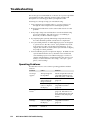
Operating Problems
The table below shows some common operating problems and their
solutions.
Problem
Cause
Solution
No image
appears.
The input signal is
incompatible.
Attach an input device that is
compatible with NTSC 3.58,
NTSC 4.43, PAL, or SECAM.
Deactivate freeze mode
(page 3-4).
Freeze mode was
entered when the
image was black.
The scaled output
rate is too high for
the display.
5-2
Change the scaled output to a
compatible resolution
(page 3-3).
The image is
frozen.
Freeze mode is on.
Deactivate freeze mode
(page 3-4). If that does not
work, unplug the power cord
from the scaler, then plug it
back in.
The image is
flashing.
The scaled output
rate is too high for
the display.
Change the scaled output to a
compatible resolution
(page 3-3).
Inputs cannot
be switched.
Autoswitch is
turned on.
Turn off autoswitch (page 2-7).
DVS 100 and DVS 150 Troubleshooting
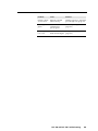
Problem
Cause
Solution
Picture controls
are not active.
Input 4 is selected
(DVS 150 only).
Switch to input 1–3. Input 4 is
pass-through only (page 1-2).
The image is
green.
The unit is
configured for
sync on green.
Turn off sync on green
(page 2-8).
The image
is too soft.
The detail level
Change the detail level
needs to be changed. (page 2-8).
DVS 100 and DVS 150 Troubleshooting
5-3
Troubleshooting, cont’d
5-4
DVS 100 and DVS 150 Troubleshooting
DVS 100 and DVS 150
A
Appendix A
Specifications
Specifications
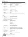
Video input
Number/type ............................... 1 composite video, 1 S-video, 1 component video (R-Y, B-Y, Y);
1 RGB pass-through (DVS 150 only)
Connectors .................................... 3 BNC female .......................... component video
1 4-pin mini-DIN female ...... S-video
1 BNC female .......................... composite video
1 15-pin HD female ............... RGB pass-through (DVS 150 only)
Nominal level(s) .......................... Analog — 0.7V to 1.0V p-p
Impedance .................................... 75 ohms
Vertical frequency ....................... 50 Hz to 60 Hz
Video output
Number/type/format ................ 1 scaled RGBHV, RGBS, RGsB
1 scaled VGA RGBHV
Connectors .................................... 6 BNC female ..................... RGB output
1 15-pin HD female .......... RGBHV output
Nominal level ............................... 0.7V p-p
Impedance .................................... 75 ohms
Vertical frequency ....................... 56 Hz, 60 Hz, or 75 Hz
Scaled VGA resolution ............... 640x480, 800x600, 832x624, 840x480, 852x480, 1024x768, 1280x768, 1280x1024,
1360x765, HDTV 480P, 720P, and 1080P
Sync
Output type ..................................
Standards ......................................
Output level .................................
Output impedance ......................
Polarity ..........................................
RGBHV, RGBS, RGsB
NTSC 3.58, NTSC 4.43, PAL, SECAM
TTL — 5.0V p-p
75 ohms
Positive or negative (switch-selectable)
Control/Remote — decoder/scaler
Serial control port ....................... RS-232, 9-pin female D connector
Baud rate and protocol ............... 9600, 8-bit, 1 stop bit, no parity
Pin configurations ....................... 1 = input 1 select
2 = TX
3 = RX
4 = input 2 select
5 = GND
6 = input 3 select
7 = input 4 select (DVS 150 only)
Contact closure ............................ 9-pin female D connector
Program control ........................... Extron’s control program for Windows®
Extron’s SIS™ (Simple Instruction Set™)
General
Power ............................................ 100VAC to 240VAC, 50/60 Hz, 30 Watts, internal, auto-switchable
Temperature/humidity ............. Storage -40° to +158°F (-40° to +70°C) / 10% to 90%, non-condensing
Operating +32° to +122°F (0° to +50°C) / 10% to 90%, non-condensing
Rack mount .................................. Yes, with optional rack shelf, part #60-190-01
Enclosure type ............................. Metal
Enclosure dimensions ................ 1.75" H x 8.75" W x 9.50" D
4.45 cm H x 22.22 cm W x 24.13 cm D
Shipping weight .......................... 6 lbs (2.7 kg)
Vibration ....................................... NSTA 1A in carton (National Safe Transit Association)
Approvals ..................................... UL, CUL, CE, FCC Class B
MTBF ............................................. 30,000 hours
Warranty ....................................... 2 years parts and labor
Specifications are subject to change without notice.
A-2
DVS 100 and DVS 150 Specifications
DVS 100 and DVS 150
B
Appendix B
Reference Information
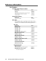
Part Numbers
Glossary
Reference
Information
Reference Information,
cont’d
Part Numbers
DVS 100 and DVS 150 part numbers
Extron Part
Part #
DVS 100
DVS 150
Signal Enhancement Products Control Program
DVS 100 and DVS 150 User’s Manual
S-video cable, 6’
60-304-01
60-317-01
29-017-01
68-459-01
26-316-02
Related part numbers
Extron Part
Part #
Universal rack shelf
60-190-01
BNC cables
Extron SHR BNC cables are super-high resolution cables. Extron
recommends using high-resolution BNC cables for signals with scan
frequencies of 15 — 125 kHz to achieve maximum performance.
Bulk cable
Extron Part
Part #
SHR bulk cable
Bulk SHR-1, 500’
Bulk SHR-1, 1000’
Bulk SHR-4, 500’
Bulk SHR-5, 500’
BNC SHR crimp connectors, qty. 50
BNC-4 Mini-HR Bulk Cable
22-098-02
22-098-03
22-099-02
22-100-02
100-075-51
Bulk BNC 4-500’ HR
Bulk BNC 4-1000’ HR
BNC 5 Mini-HR Bulk Cable
22-032-02
22-032-03
Bulk BNC 5-500’ HR
Bulk BNC 5-1000’ HR
BNC 5 Plenum Mini-HR BULK Cable
22-020-02
22-020-03
Bulk BNC 5-500’ HRP
Bulk BNC 5-1000’ HRP
Install Plenum Bulk Cable
22-103-02
22-103-03
Bulk Install Plenum, 500’
Bulk Install Plenum, 1000’
22-111-03
22-111-04
Assorted connectors
BNC Connectors
BNC Mini-HR crimp connectors, qty. 50
BNC SHR crimp connectors, qty. 50
BNC Bulkhead connectors, qty. 50
(for custom wall plates)
B-2
DVS 100 and DVS 150 Reference Information
100-074-51
100-075-51
100-076-51
Pre-cut cables
BNC-4 HR cable is used for RGBS cable runs, and BNC-5 is used for
RGBHV cable runs. Either type can also be used for RGsB (sync on
green). All Extron BNC cables have male gender connectors at both
ends. A plenum version of the BNC-5 HR cable is also available.
BNC-4 HR Cable
BNC-4-25’ HR (25 feet/7.5 meters)
BNC-4-50’ HR (50 feet/15.0 meters)
BNC-4-75’ HR (75 feet/23.0 meters)
BNC-4-100’ HR (100 feet/30.0 meters)
BNC-4-150’ HR (150 feet/45.0 meters)
BNC-4-200’ HR (200 feet/60.0 meters)
BNC-4-250’ HR (250 feet/75.0 meters)
BNC-4-300’ HR (300 feet/90.0 meters)
BNC-5 HR Cable
26-210-04
26-210-05
26-210-06
26-210-07
26-210-08
26-210-09
26-210-54
26-210-53
BNC-5-25’ HR (25 feet/7.5 meters)
BNC-5-50’ HR (50 feet/15.0 meters)
BNC-5-75’ HR (75 feet/23.0 meters)
BNC-5-100’ HR (100 feet/30.0 meters)
BNC-5-150’ HR (150 feet/45.0 meters)
BNC-5-200’ HR (200 feet/60.0 meters)
BNC-5-250’ HR (250 feet/75.0 meters)
BNC-5-300’ HR (300 feet/90.0 meters)
26-260-03
26-260-04
26-260-16
26-260-05
26-260-12
26-260-06
26-260-18
26-260-14
Bulk cable in lengths up to 5000’ rolls is available with or without
connectors.
Glossary
Autoswitch mode — Automatically selects the active input device. If
more than one input device is on, the device with the highest
video quality is selected.
Blanking, top and bottom — A feature that removes noise and
unwanted information, such as tape head switching and closed
captioning, from the top and bottom portions of the screen.
Channel reset — Reconfigures the settings for the active input to the
original factory settings.
Detail filter — Controls the sampling of the horizontal plane, thereby
affecting the sharpness or smoothness of the scaled image.
Digital video scaler — See scaler.
Executive mode — Locks out all front panel functions except input
selection.
Freeze — Locks the output display to the current image.
Motion compensation — Eliminates scan lines and “jaggies” in motion
video.
Precise image processing — A combination of three technologies
(motion compensation, three-line adaptive comb filter, and quad
standard decoder) that produces the best possible upscaled image.
Quad standard decoder — A device, compatible with the NTSC 3.58,
NTSC 4.43, SECAM, and PAL standards, that separates the RGBS
(red, green, blue, and sync) signals from a composite, S-video, or
component video signal.
DVS 100 and DVS 150 Reference Information
B-3
Reference Information, cont’d
Scaling — Changes the size of an image without changing its shape.
Scaling can be used when the image size does not fit the display
device. A digital video scaler converts an NTSC, PAL, or SECAM
image to a size that can be displayed on a device with a fixed
resolution and aspect ratio, such as an LCD (liquid crystal display)
projectors, DLP (digital light processing) projectors, or plasma
projector .
Sync polarity — A circuit can be designed to operate on the positivegoing or negative-going part of the sync pulse. The DVS 100 and
DVS 150 have menu options that allow you to select which edge
(positive or negative) to trigger on.
System reset — Reconfigures all DVS 100 settings to the original factory
settings.
Three-line adaptive comb filter — A filter circuit that passes a series of
frequencies and rejects the frequencies in between, producing a
frequency response that resembles the teeth of a comb. Its precise
separation of the chroma and luma signals reduces both cross
chroma and cross luma artifacts (chroma crawl or “zipper”
artifacts). It preserves more detail in the black-and-white,
resulting in a better quality picture. Although comb filters are
successful in reducing artifacts, they may also cause a certain
amount of loss of resolution in the picture. Each DVS 100 and
DVS 150 uses a three-line adaptive comb filter, which examines
three scan lines instead of one, producing a picture of higher
quality than one produced by a standard comb filter.
B-4
DVS 100 and DVS 150 Reference Information
FCC Class B Notice
This equipment has been tested and found to comply with the limits for a Class B digital device,
pursuant to part 15 of the FCC Rules. These limits are designed to provide reasonable protection
against harmful interference in a residential installation. This equipment generates, uses and can
radiate radio frequency energy and, if not installed and used in accordance with the instructions,
may cause harmful interference to radio communications. However, there is no guarantee that the
interference will not occur in a particular installation. If this equipment does cause harmful
interference to radio or television reception, which can be determined by turning the equipment off
and on, the user is encouraged to try to correct the interference by one or more of the following
measures:
• Reorient or relocate the receiving antenna.
• Increase the separation between the equipment and receiver.
• Connect the equipment into an outlet on a circuit different from that to which the receiver is
connected.
• Consult the dealer or an experienced radio/TV technician for help.
This unit was tested with shielded cables on the peripheral devices. Shielded cables must be used
with the unit to ensure compliance.
Extron’s Warranty
Extron Electronics warrants this product against defects in materials and workmanship for a period
of two years from the date of purchase. In the event of malfunction during the warranty period
attributable directly to faulty workmanship and/or materials, Extron Electronics will, at its option,
repair or replace said products or components, to whatever extent it shall deem necessary to restore
said product to proper operating condition, provided that it is returned within the warranty period,
with proof of purchase and description of malfunction to:
USA, Canada, South
America, Central
America, and Asia:
Extron Electronics
1230 South Lewis Street
Anaheim, CA 92805, U.S.A.
Europe, Africa, and the
Middle East:
Extron Electronics, Europe
Beeldschermweg 6C
3821 AH Amersfoort
The Netherlands
This Limited Warranty does not apply if the fault has been caused by misuse, improper handling
care, electrical or mechanical abuse, abnormal operating conditions or non-Extron authorized
modification to the product.
If it has been determined that the product is defective, please call Extron and ask for an Applications
Engineer at (714) 491-1500 (USA), 31.33.453.4040 (Europe), or 65.226.0015 (Asia) to receive an RA# (Return
Authorization number). This will begin the repair process as quickly as possible.
Units must be returned insured, with shipping charges prepaid. If not insured, you assume the risk
of loss or damage during shipment. Returned units must include the serial number and a
description of the problem, as well as the name of the person to contact in case there are any
questions.
Extron Electronics makes no further warranties either expressed or implied with respect to the
product and its quality, performance, merchantability, or fitness for any particular use. In no event
will Extron Electronics be liable for direct, indirect, or consequential damages resulting from any
defect in this product even if Extron Electronics has been advised of such damage.
Please note that laws vary from state to state and country to country, and that some provisions of
this warranty may not apply to you.
EXTRON ELECTRONICS/RGB SYSTEMS, INC.
1230 South Lewis Street, Anaheim, CA 92805
800.633.9876 714.491.1500 FAX 714.491.1517
U.S.A.
EXTRON ELECTRONICS, EUROPE
Beeldschermweg 6C, 3821 AH Amersfoort
+31.33.453.4040 FAX +31.33.453.4050
The Netherlands
EXTRON ELECTRONICS, ASIA
41B Kreta Ayer Road, Singapore 089003
+65.226.0015 FAX +65.226.0019
Singapore
EXTRON ELECTRONIC INFORMATION
EXTRONWEB™: www.extron.com
EXTRONFAX™: 714.491.0192
24-hour access—worldwide!