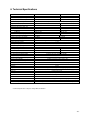
1
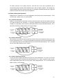
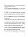
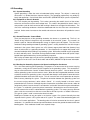
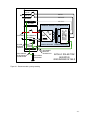
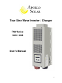
True Sine Wave Inverter / Charger
TSW Series:
3224 / 4048
User’s Manual
-0-
TABLE OF CONTENTS
Purpose ……………………………………………………………………………………
3
Scope ………………………………………………………………………………………
3
Audience
3
…………………………………………………………………………………
Conventions Used
………………………………………………………………………
Important Safety Instructions
General Precautions
…………………………………………………………
4
…………………………………………………………………
4
…………………………………………………………………
Personal Precautions
1. Introduction
3
5
…………………………………………………………………………
6
1.1 Introduction to the Inverter … ………………………………………………...…
6
1.2 Indicators and Settings
7
2. The Battery Charger
……………………………………………………….………
8
……………………………………………………………..
8
…………………………………………………………………….
8
……………………………………………………………………………………..
8
2.1 Theory of Operation
2.2 Transfer Relay
2.2.1 Current Rating
2.2.2 Transfer Speed
3. Installation
………………………………………………….………
…………………………………………………………………… 8
…………………………………………………………………………….
3.1 Installation Steps
………………………………………………………………….. 9
3.11 Selecting a Proper Location
………………………………………………………………………..
3.12 Inverter Mounting (vertical)
……………………………………………………………………….. ..
3.13 Inverter Mounting (horizontal)
4. Wiring
9
……………………………………………………………………….
9
10
10
…………………………………………………………………………………… 11
4.1 Battery Information
4.1.1 Battery Size
………………………………………………………………... 12
………………………………………………………………………………………….
4.1.2 Battery Bank Sizing
12
………………………………………………… ……………………………..
12
………………………………………………………………………………
12
4.1.3 Monthly Maintenance
……………………………………….. ………………………..
13
4.1.4.1 Parallel Connection
………………………………………………………………………….
13
4.1.4.2 Series Connection
…………………………………………………………………………...
13
4.1.4 Battery Hook-up Configurations
…………………………………………………………………
13
………………………………………………………………………………...
14
4.1.4.3 Series-Parallel Connection
4.1.5 Battery Installation
…………………………………………………………………………….
14
……………………………………………………………………………
14
………………………………………………………………………………
14
………………………………………………………………………...
15
4.1.5.1 Battery Location
4.1.5.2 Battery Enclosure
4.1.5.3 Battery Cabling
4.2 Grounding
4.2.1 System Grounding
……………………………………………………………………………….
15
-1-
4.2.2 Equipment or Chassis Grounds
………………………………………………………………
15
…………………………………………………………..
15
4.2.4 Bonding the Grounding System to the Neutral and Negative Conductors ……. ………….
15
4.3 AC and DC Wiring ………………………………………………………………
17
4.2.3 Ground Electrodes / Ground Rods
4.3.1 DC Wiring ………………………………………………………………………………………..
19
4.3.1.1 DC Cable Connections …………………………………………………………………..
20
4.3.1.2 Wiring the Battery Bank …………………………………………………………………
20
4.3.1.3 Battery Temperature Sensor Installation ………………………………………………
21
4.3.1.4 Wiring the Inverter to the Battery Bank ………………………………………………..
21
4.3.2 AC Wiring ………………………………………………………………………………………
23
4.3.2.1 AC Wire Size and Overcurrent Protection ……………………………………………
24
4.3.2.2 AC Input and Output Wiring Connections ……………………………………………
24
4.4 Apollo TSW Inverter Stacking ………………………………………………..
25
4.4.1 Connection Diagram ………………………………………………………………………….
25
4.4.2 Parameter Setting …………………………………………………………………………….
26
4.4.3 Parallel Operation …………………………………………………………………………….
26
5. Operation
………………………………………………………………………..
27
5.1 Functional Test and Initial Setup ………………………………………… ..
27
5.2 LCD Screen Descriptions ………………………………………………………………..
27
5.2.1 Startup Screen ……………………………………………………………………………….
27
5.2.2 Initial Status Screen ………………………………………………………………………..
27
5.2.3 Inverter Mode Main Status Screen ……………………………………………………….
27
5.2.4 Charger Mode Main Status Screen ……………………………………………………….
28
5.2.5 Search Mode ………………………………………………………………………………..
28
5.2.6 Error Messages ……………………………………………………………………………...
28
5.3 System Default Settings ………………………………………………………………….
29
6. Technical Specification
7. Troubleshooting
……………………………………………………….
30
……………………………………………………………….
31
8. Service and Support
…………………………………………………………..
31
Five Year Limited Warranty Information ………………………………………..
32
-2-
Purpose
The purpose of this Installation and Operation Manual is to provide explanations and procedures for
installing, operating, maintaining, and troubleshooting TSW series of Inverter/charger.
Scope
The Manual provides safety guidelines, detailed planning and setup information, procedures for installing
the inverter, as well as information for operating and troubleshooting the unit. It does not provide details or
suggestions on specific brands of batteries – consult individual battery manufacturers for this information.
Audience
This manual is intended for anyone who needs to install and operate the TSW inverter/charger. Installers
should be certified electricians or technicians.
Conventions Used
WARNING
Warnings identify conditions or practices that could result in personal injury or loss of life.
Les avertissements identifient les conditions ou les pratiques qui pourraient avoir comme conséquence le
dommage corporel ou les pertes humaines.
CAUTION
Cautions identify conditions or practices that could result in damage to the unit or other equipment.
Les attentions identifient les conditions ou les pratiques qui pourraient avoir comme conséquence les
dommages à l'unité ou à tout autre équipement.
IMPORTANT
These notes describe things that are important to know, but not as serious as a caution or warning.
Ces notes décrivent les choses il est importante savoir que, mais pas aussi sérieux qu'une attention ou un
avertissement.
Abbreviations and Acronyms
AC
ASNET
COM
Alternating Current
Apollo Solar Network Interface
COMmunications Port
DC
Direct Current
LED
Light Emitting Diode
PV
PVGFI
RE
RMA
TSW Inverter
Photovoltaic
PV Ground Fault Interrupter
Renewable Energy
Return Material Authorization
TSW series Inverter/charger
-3-
IMPORTANT SAFETY INSTRUCTIONS
INSTRUCTIONS DE SÉCURITÉS IMPORTANTES
SAVE THESE INSTRUCTIONS
CONSERVER CES INSTRUCTIONS
General Precautions
1. Before using the TSW inverter, please read all instructions and cautionary marks on (1) the inverter, (2)
the batteries, and (3) all appropriate sections of this instruction manual.
2. Do not expose INVERTER to rain, snow, or liquids of any type. The INVERTER is designed for indoor
mounting only. Protect the inverter from splashing if used in vehicle applications.
3. Do not disassemble the INVERTER; take it to a qualified service center when service or maintenance
is required. Incorrect re-assembly may result in risk of electric shock or fire.
4. To reduce risk of electric shock, disconnect all wiring before making any attempt to maintain or clean.
Simply turning off the INVERTER will not reduce this risk.
WARNING
5. WORKING IN THE VICINITY OF A LEAD ACID BATTERY IS DANGEROUS. BATTERIES
GENERATE EXPLOSIVE GASES DURING NORMAL OPERATION. Provide ventilation to outdoors
from the battery compartment. The battery enclosure should be designed to prevent accumulation and
concentration of hydrogen "pockets" at the top of the compartment. Vent the battery compartment from
the highest point. A sloped lid can also be used to direct the flow through the vent opening location.
ATTENTION:
Une batterie peut présenter un risque de choc électrique, de brûlure par transfert d’énergie, d’incenie ou
d’explosion des gaz dégagés. Suivre les précautions qui s’imposent.
6. NEVER charge a frozen battery.
7. No terminals or lugs are required for hook-up of the AC wiring. AC wiring must be no less than
2
10 AWG (5.3mm ) gauge copper wire and rated for 90ººC or higher. Crimped and sealed copper
ring terminal lugs with a 5/16 inch hole should be used to connect the battery cables to the DC
terminals of the INVERTER. Soldered cable lugs are also acceptable .See section on battery cable
sizing for more details for your application (see Table 4.1 page 18).
8. Torque all AC wiring connections to 30 in-lbs (3.4 N-m). Torque all DC cable connections to 5 ft-lbs
(6.78 N-m). Be extra cautious when working with metal tools on or around batteries. The potential of
dropping a tool causing the batteries or other electrical parts resulting in sparks could cause an
explosion. Tools required for AC wiring connections: wire strippers, 1/2"(13mm) open-end wrench or
socket, Phillips screw driver #2, slotted screw driver 3/16"(4.6 mm) blade.
9. The INVERTER must be used with a battery supply of nominal voltage that matches the last two digits
of the model number; e.g., 24 volts with a TSW3224, and 48 volts with a TSW4048.
10. GROUNDING INSTRUCTIONS. This battery charger should be connected to a grounded, permanent
wiring system. For most installations, the negative battery conductor should be bonded to the
grounding system at one, and only one, point in the system. All installations should comply with all
national and local codes and ordinances.
-4-
11. Personal Precautions
1. Someone should be within voice range when you work near batteries in case of an emergency.
2. Have plenty of fresh water and soap nearby in case battery acid contacts skin, clothing, or eyes.
3. Wear complete eye and clothing protection. Avoid touching eyes while working near batteries.
Wash your hands when done.
4. If battery acid contacts skin or clothing, immediately wash with soap. If acid enters eyes
immediately, flood eyes with cool, running water for at least 15 minutes. Immediately seek medical
attention.
5. Never smoke or allow a spark or flame in the vicinity of a battery or generator.
6. Be extra cautious when working with metal tools on and around batteries. The potential of dropping
a tool causing the batteries or other electrical parts resulting in sparks could cause an explosion.
7. Remove personal metal items such as rings, bracelets, necklaces, and watches when working with
a battery. A battery can produce a short -circuit current, which is high enough to weld a ring or the
like to metal causing severe burns.
8. If a remote or automatic generator starter system is used to disable the automatic starting circuit
and/or disconnect the generator from its starting battery while servicing to prevent accidental
starting during servicing.
-5-
1. Introduction
1.1 Introduction to the Inverter
The TSW series inverter is not only an inverter but also contains a powerful intelligent charger.
Actually, it contains three modules in a single unit: inverter, charger and switch.
The TSW series inverter is a heavy-duty, continuous working module generating a sinusoidal wave
from a 24V, or 48V battery bank, which can supply energy to various loads such as resistive load
(heater), inductive load (air conditioners, refrigerator), motors (vacuum cleaners), and rectifier load
(computer). All TSW series are designed to work in heavy load condition. De-rating is not necessary.
It provides a rapid and complete charging process.
The TSW series are True Sine wave Inverters, not to be confused with Modified Sine wave models on
the market. Unlike the modified sine wave counterpart, a true sine wave inverter provides a pure
signal which will not interfere with some of the sensitive electronic equipment currently on the market.
The TSW series inverters provide a 120/240 Volt AC Split-Phase input and output. No external
transformers are required for step up, step down or balancing, thus saving added costs, installation
time, and several points of efficiency. The output provides 240 volts for well pumps, appliances, or
shop tools while providing 120 volts for standard circuits. Either side of the output line can supply up
to 75% of the total load. The input can accept the line or 240 volt AC generators. The transfer relay
is internal.
The smart charger can be set with different charging profiles and battery capacities to match in
various battery types and sizes. The switch module automatically diverts the energy transfer path
between inverter and utility source. When the utility source is lower than the transfer level, the path
switches to the inverter. Otherwise the load is conducted to the utility source. The transfer time is
1/4~1/2 of the total cycle time. The high power charger (100A) can charge a 24V/1000 AH battery
bank in 10 hours. For example, a single unit of Inverter TSW 3224 with a 1000 AH battery bank can
supply a 3200W workload for over 6 hours after a charge of 10 hours.
TSW series is an extremely good choice for utility back up power. However, it also can be used as a
UPS for computers.
-6-
1.2 Indicators and Settings
Figure 1.0: TSW Control Panel
Display: This is a 16 character by 2 line LCD which provides operational information and setup prompts.
Note: For detailed description of the LCD screens, refer to the Operation Section 5.0.
On LED: Glows green to indicate that the inverter is powered on (i.e. connected to the battery and receiving
power).
Status LED: Glows amber to indicate the following functions:
Page Key: Allows the user to scroll through the various LCD screens (refer to Operation Section for
description of individual screen data.
Standby Key: Allows the user to enter/exit standby mode.
Audible Indication: Provides a loud audio tone to signal mode change or error conditions.
-7-
2. The Battery Charger
2.1 Theory of Operation
The internal battery charger and automatic transfer relay allow the unit to operate as either a battery
charger or inverter, but not at the same time. An external source of AC power (e.g. line power or
generator) must be supplied to the Inverter’s AC input in order to allow it to operate as a battery
charger. When the unit is operating as a charger, AC loads are powered by the external source (i.e.,
generator or public power).
The Battery Charger utilizes a five stage charger algorithm (Bulk, Absorb, Float, Equalize and
Standby). Figure 2.0 is a chart which illustrates the operation of this unit.
APOLLO SOLAR T80 TurboCharger tm
BATTERY CHARGING DETAILS
15
ABSORB SET POINT
B
BATTERY VOLTAGE
14
FLOAT SET POINT
13
E
12
11
CHARGING CURRENT
10
80
A MAX CHARGE CURRENT SET POINT
70
60
50
40
30
20
C
10
F
START
0
BULK CHARGE MODE
(CONSTANT CURRENT)
(Approx 80% of energy is replaced
in the bulk mode.)
ABSORB MODE
(CONSTANT
VOLTAGE)
2 HOURS
FLOAT
MODE
STANDBY
Inverter On
D
Figure 2.0: Battery Charger operation
2.2 Transfer Relay
2.2.1 Current Rating
40 Amps per leg
2.2.2 Transfer Speed
The transfer time is 1/4~1/2cycle (8ms max).
-8-
3.0 Installation
3.1 Installation Steps
3.1.1 Selecting appropriate Location
The Inverter is a sophisticated electronic device and should be treated accordingly. When selecting
the operating environment for the inverter, do not think of it in the same terms as other equipment that
works with it (e.g. Batteries, diesel generators, motor generators, washing machines, etc). It is a
highly complex microprocessor controlled device. It should be treated similarly to other electronic
devices (e.g. entertainment equipment, computers, etc.) The use of conformal coated circuit boards,
plated copper bus bars, powder coated metal components, and stainless steel fasteners allows the
unit to function in hostile environments, but high humidity/varying temperature (condensing)
environment should be avoided. In a condensing environment the life expectancy of the inverter
cannot be determined and the warranty is voided.
CAUTION
It is in your best interest to install the Inverter in a dry protected location away from sources of high
temperature and moisture. Exposure to saltwater is particularly destructive and potentially
hazardous.
ATTENTION
Il est dans votre meilleur intérêt d'installer l'inverseur dans un endroit protégé sec à partir des sources
de température et d'humidité. L'exposition à l'eau de mer est particulièrement destructive et
potentiellement dangereuse.
Locate the Inverter as close as possible to the batteries in order to keep the battery cables short.
However, do not locate the inverter in the same compartment as non-sealed batteries. The Inverter
may be located in a compartment with other sealed electronic equipment. Batteries generate
hydrogen and oxygen. If accumulated, this combination could be ignited by an arc resulting from
connection of the battery cables or by switching a relay.
Do not mount the inverter in a closed container. Unrestricted airflow is required to operate at high
power for sustained periods of time. Without it, the protection circuitry will activate and reduce the
maximum power available.
-9-
3.1.2 Inverter Mounting (Vertical)
The TSW Series inverter may be mounted vertically or horizontally. The vertical
configuration is preferable when using the Apollo Solar Switch Gear. Apollo
Switch Gear provides a convenient method for mounting other Balance of
System (BOS) components such as circuit breakers, shunts, etc.
The next section shows dimensions which will aid in mounting the unit. Be sure
to mount on a strong stable surface (some suggestions follow). The next section
details horizontal mounting of the TSW series Inverter.
Please Note, the TSW Series inverter is shipped with the Display/Keypad
mounted for the vertical mounting configuration. To position it for
horizontal mounting, please follow the steps below:
•
•
•
Remove the four (4) Display/Keypad mounting screws
Carefully rotate the Display/Keypad 90 degrees
Re-install the mounting screws using care not to over tighten.
Horizontal mounting is necessary when using the TSW Series Inverter as a replacement for other
inverters with a similar form factor.
3.1.3 Inverter Mounting (Horizontal)
It is recommended that the TSW Inverter be mounted on a ¾” plywood sheet which is nailed or
screwed into the wall studs. Ensure that the plywood spans across three wall studs for adequate
support. Alternately, when mounting horizontal, two 2x4s may be placed 8” on center to mount the
inverter. Again, be sure to span three studs for adequate support.
It is best to locate the Inverter approximately 4 – 5 feet from the floor.
- 10 -
4. Wiring
NOTE: AC
NEUTRAL AND
DC NEGATIVE
WIRES ARE
WHITE, BUT ARE
SHOWN AS
LIGHT GRAY.
AC OUT AC IN
APOLLO SOLAR
TSW 3224
APOLLO SOLAR
TSW 3224 or TSW 4048
TRUE SINE WAVE
INVERTER/CHARGER
CAT-5
ETHERNET
CABLE
INTERNET
APOLLO
COMMUNICATION
GATEWAY
TRUE SINE WAVE
INVERTER / CHARGER
OPTIONAL
REMOTE DISPLAY
ACG-1
Solar Power Center
ASNET
APOLLO
SHUNT
BOARD
DC IN
AC
GFP
- BUS
250
+BUS
AC
AWG #3
125V DC
BREAKERS
TurboCharger
PV
IN
AC BREAKERS
BAT
OUT
BATTERY
CHASSIS
EARTH
GND
PV
ARRAY
BATTERY
VOLTAGE
SENSE
WIRES
6V
BATT
PV
IN
APOLLO SOLAR T80
PV CHARGE
CONTROLLER
GND
PV IN
240VAC
IN FROM
LINE OR
GENERATOR
240VAC
OUT TO
LOAD
PANEL
WIRED FOR 120/240VAC SPLIT PHASE
* GND NOTE: IF THIS SYSTEM IS THE SOURCE OF THE
BUILDING POWER, THE AC NEUTRAL MUST BE
CONNECTED TO EARTH GROUND AT THIS POINT ONLY.
IF THE SYSTEM HAS AN AC INPUT AT A CIRCUIT
BREAKER BOX, THE AC NEUTRAL MUST BE TIED TO
GROUND AT THAT SOURCE OF POWER ONLY.
6V
BATT
6V
BATT
6V
BATT
APOLLO SOLAR
BATTERY
TEMPERATURE
SENSOR
PV INPUT
(UP TO 75A)
WIRES MAY BE AS
LARGE AS AWG #2
BATTERY BOX AND BATTERIES
(MADE BY OTHERS)
BATTERY MAY BE 24 OR 48V
DEPENDING ON THE INVERTER.
(24 VOLT VERSION SHOWN)
STRINGS MAY BE TIED IN
PARALLEL FOR MORE AMP-HRS.
Figure 4.0: Typical system wiring diagram (single inverter).
- 11 -
4.1 Battery Information
4.1.1 Battery Size
Batteries are the Inverter’s fuel tank. The larger the batteries the longer the INVERTER can operate
before recharging is necessary. An undersized battery bank results in reduced battery life and
disappointing system performance.
Avoid discharging batteries to more than 50% of their capacity too often. Under extreme conditions,
such as a severe storm or a long utility outage, cycling to a discharge level of 80% is acceptable.
Totally discharging a battery may result in permanent damage and reduced life.
For stand-alone applications, battery size should provide between 3 and 5 days of storage before
needing to be recharged. The power contribution from other charging sources is not included in this
calculation to duplicate the conditions present during a cloudy or windless period. This is often
referred to as the "number of days of autonomy." If the system is a hybrid system with daily generator
runs periods then the battery size may be smaller. During cloudy periods the generator would be
expected to run longer. Utilities back up applications often have very small batteries. The minimum
recommended battery capacity is 100 amp-hours@24vdc, and 50 amp-hours@48vdc.
4.1.2 Battery Bank Sizing
To determine the proper battery bank size, compute the number of amp hours that will be used during
charging cycles. Doubling the expected amp hour usage ensures that the batteries will not be overly
discharged and extends battery life. To compute total amp hours usage, determine the amp hour
requirements of each load and total them.
You can compute your battery requirements using the nameplate rating of your appliances. The
formula is WATTS=VOLTS X AMPS. Divide the wattage of your load by the battery voltage to
determine the amperage the load will draw from the batteries.
If the AC current is known, then the battery amperage will be as follows:
AC Current x AC Voltage / Battery Voltage = DC amps.
Multiply the amperage by the number of hours that the load will operate, and you have a reasonable
estimate of amp hours.
Motors are normally marked with their running current rather than their starting current. Starting
current may be three to six times running current. Manufacturer's literature may provide more
accurate information than the motor nameplate. For larger motors, increasing the battery size
indicates that the high demand for start-ups should be required.
Follow this procedure for each individual load. Add the resulting amp hour requirements for each load
to arrive at a total requirement. The minimum properly sized battery bank should be approximately
double this amount. This will allow the battery to be cycled only 50% on a regular basis.
4.1.3 Monthly Maintenance
The level of the electrolyte of a flooded battery should be checked monthly. It should be about 1/ 2"
above the top of the plates, but not completely full. Don't overfill the batteries or the electrolyte will
seep out during charging. Refill the batteries with distilled water. Avoid "spring" water and regular tap
water as they may have high mineral levels that can affect the battery chemistry and reduce life.
Check the battery interconnections for tightness and corrosion. If corrosion is found, disconnect the
cables; clean them with a mild solution of baking soda and water. DO NOT ALLOW THE SOLUTION
TO ENTER THE BATTERY. Rinse the top of the battery with clean water when finished (replace the
caps first.)
- 12 -
To reduce corrosion on the battery terminals, coat them with a thin layer of petroleum jelly or
anti-corrosion grease available from automotive parts stores or battery suppliers. Do not apply any
material between the terminal and the cable lugs, the connection should be metal to metal. Apply the
protective material after the bolts have been tightened
4.1.4 Battery Hook-up Configurations
Battery banks of substantial size can be configured by connecting several smaller batteries. There
are three ways: parallel, series, or series-parallel.
4.1.4.1 Parallel Connection
Batteries are connected in parallel when all of the positive terminals and all of the negative terminals
of a group of batteries are connected. In a parallel configuration the battery bank has the same
voltage as a single battery and an amp/hour rating equal to the sum of the individual batteries. This is
done when the battery voltage matches the inverter voltage.
4.1.4.2 Series Connection
When batteries are connected with the positive terminal of one to the negative terminal of the next,
they are connected in series. In a series configuration the battery bank has the same amp/hour rating
as a single battery and an overall voltage equal to the sum of the individual batteries. This is common
with 24 volt or higher battery-inverter systems.
4.1.4.3 Series-Parallel Connection
As the name implies, both of the above techniques are used in combination. The result is an increase
in both the voltage and the capacity of the total battery bank. This is done very often to make a larger,
higher voltage battery bank out of several smaller, lower voltage batteries. This is common with all
battery-inverter system voltages.
- 13 -
4.1.5 Battery Installation
CAUTION
Batteries can produce extremely high currents in short-circuit. Be very careful working around them.
Read the important safety instructions at the beginning of this manual and the battery supplier's
precautions before installing the Inverter and batteries.
ATTENTION
Les batteries peuvent produire les courants extrêmement élevés dans le court-circuit. Soyez
fonctionnement très soigneux autour de elles. Lisez les instructions de sûreté importantes au début
de ce manuel et de la batterie supplier' ; précautions de s avant d'installer l'inverseur et les batteries.
4.1.5.1 Battery Location
Batteries should be located in an accessible location with nothing restricting access to the battery
caps and terminals. At least two feet of clearance above is recommended. Locate as close as
possible to the Inverter, but do not limit access to the Inverter and the Inverter's disconnect. Do not
locate the inverter in the same compartment with non-sealed batteries (sealed batteries are
acceptable) as the gasses produced during charging are very corrosive and will shorten the life of the
inverter.
Battery to inverter cabling should be no longer than required. For 24 VDC systems do not exceed 10
feet (one way) if 4/0 AWG cables are used. For 48 VDC systems do not exceed 20 feet (one way) if
4/0 AWG cables are used.
4.1.5.2 Battery Enclosure
Batteries should be protected within a ventilated, locked enclosure or room. The enclosure should be
ventilated to the outdoors from the highest point to prevent accumulation of hydrogen gasses that are
released from the battery during charging. An air intake should also be provided at a low point in the
enclosure to allow air to enter to promote good ventilation. For most systems a one-inch diameter
vent pipe from the top of the enclosure is adequate. A sloped top can help direct the hydrogen to the
vent location and prevent pockets of hydrogen from occurring. The enclosure should also be capable
of containing at least one battery cell worth of electrolyte in the event a spill or leak occurs. The
enclosure should be made of acid resistant material or have an acid resistant finish. If the batteries
are located outdoors, the enclosure should be rainproof and have mesh screens over any openings
to prevent insects and rodents from entering. Before placing the batteries in the enclosure, cover the
bottom with a layer of baking soda to neutralize any acid that might be spilled in the future.
4.1.5.3 Battery Cabling
Heavy cables should be used to connect individual batteries to configure a larger battery
bank. The actual size of the cable depends upon whether the batteries are connected in parallel or
series. Generally, the cables should not be smaller than the main battery cables to the inverter. E.g.
If the main cables are 4/0 AWG the battery interconnects should be 4/0 AWG.
It is preferable to connect the batteries first in series and then in parallel when connecting smaller
batteries. The best option is to connect the batteries both in series and parallel in a configuration
often called "cross-trying'. This requires additional cables but reduces imbalances in the battery and
can improve the overall performance. Consult your battery supplier for more information regarding
the hook-up configuration required for your system.
- 14 -
4.2 Grounding
4.2.1 System Grounding
System grounding is often the most misunderstood wiring concept. The subject is more easily
discussed if it is divided into three separate subjects. The grounding requirements vary widely by
locale and application. Consult local codes and the NEC (ANSI/NFPA 70) for specific requirements.
4.2.2 Equipment or Chassis Grounds
This is the simplest part of grounding. This involves connecting the metallic chassis of the various
enclosures to have them at the same voltage level. This reduces the potential for electric shock. It
also provides a path for fault currents to flow resulting in blown fuses or tripped circuit breakers. The
size of the connecting conductors should be coordinated with the size of the over current devices
involved. Under some circumstances the conduit and enclosures themselves will provide the current
paths.
4.2.3 Ground Electrodes / Ground Rods
There are two purposes of the grounding electrode, also known as a ground rod. The first is to
"bleed" off any electrical charge that may accumulate in the electrical system. The second is to
provide a path for 'induced electromagnetic energy' or lightning to be dissipated. The size of the
conductor to the grounding electrode or grounding system is usually based on the size of the largest
conductor in the system. Most systems use a 5/8' (16mm) copper plated rod 6 feet (2meters) long
driven in to the earth as a grounding electrode. It is also common to use copper wire placed in the
concrete foundation of the building as a grounding system. While either method may be acceptable,
the local code will prevail. Connection to the ground electrode should be done with special clamps
located above ground where they can be periodically inspected.
Well casings and water pipes may be used as grounding electrodes. Under no circumstance should
a gas pipe or line be used. Consult local codes and the NEC (ANSI/NFPA 70) for more information.
4.2.4 Bonding the Grounding System to the Neutral and Negative Conductors
This is the most confusing part of grounding. The purpose is to connect one of the current carrying
conductors, usually the AC neutral and DC negative, to the grounding system. This connection is
why we call one of the wires "neutral" in North American electrical systems. You can touch this wire
and the grounding system and not receive a shock. When the other ungrounded conductor, the hot
or positive, touches the grounding system, current will flow through it to the point of connection to the
grounded conductor and back to the source. This will cause the over current protection to shop the
flow of current, protecting the system. The point of connection between the grounding system and
the current carrying conductor is often called a "bond." It is usually located in the over current
protection devices' enclosure. Although the point of connection can be done at the inverter, codes do
not generally allow it since the inverter is considered a "serviceable” item which may be removed from
the system. In residential systems the point of connection is located at the service entrance panel.
In some countries the neutral is not bonded to the grounding system. This means you may not know
when a fault has occurred since the over current device will not trip unless a "double" fault occurs.
This type of system is used in some marine electrical codes.
Bonding must be done at only one point in an electrical system. Our systems inherently have two
separate electric systems- a DC system and an AC system. This means that two bonding points will
occur in all inverter applications. The bonding point will also be connected to the chassis ground
conductors. It is common to have two separate conductors connect the ground electrode and the two
bonding points. Each conductor should use a separate clamp.
- 15 -
AC SYSTEM
HOT IN
AC
HOT IN
HOT OUT
HOT OUT
NEUTRAL
NEUTRAL
NEUTRAL
BUS-BAR
DC SYSTEM
SYSTEM
BONDING
JUMPERS
GROUNDING
ELECTRODE
CONDUCTOR
DC
DC NEGATIVE
BUS-BAR
CHASSIS GROUND
GROUND
BUS-BAR
EQUIPMENT
GROUND
CONDUCTOR
GROUNDING
ELECTRODE
AC TRANSFER
SWITCH AND
FILTER BOARD
TO
BATTERY
APOLLO SOLAR TSW INVERTER
CHASSIS GROUND
APOLLO SOLAR TSW
INVERTER
GROUNDING DETAILS
Figure 4.1: Recommended system grounding
- 16 -
4.3 AC and DC Wiring
NOTE: AC NEUTRAL AND
DC NEGATIVE WIRES ARE
WHITE, BUT ARE SHOWN
AS LIGHT GRAY.
AC OUT AC IN
APOLLO SOLAR
TSW 3224
APOLLO SOLAR
TSW 3224 or TSW 4048
TRUE SINE WAVE
INVERTER/CHARGER
CAT-5
ETHERNET
CABLE
INTERNET
APOLLO
COMMUNICATION
GATEWAY
TRUE SINE WAVE
INVERTER / CHARGER
OPTIONAL
REMOTE DISPLAY
ACG-1
APOLLO SOLAR
SWITCHGEAR
MODULE
ENCLOSURE
Solar Power Center
ASNET
APOLLO
SHUNT
BOARD
DC IN
AC
AWG #3
- BUS
GFP
250
+BUS
AC
AWG #3
125V DC
BREAKERS
TurboCharger
PV
IN
AC BREAKERS
BAT
OUT
BATTERY
CHASSIS
EARTH
GND
6V
BATT
PV
IN
PV
ARRAY
BATTERY
VOLTAGE
SENSE
WIRES
APOLLO SOLAR T80HV
PV CHARGE
CONTROLLER
GND
PV IN
240VAC
IN FROM
LINE OR
GENERATOR
240VAC
OUT TO
LOAD
PANEL
WIRED FOR 120/240VAC SPLIT PHASE
* GND NOTE: IF THIS POWER CENTER IS THE SOURCE
OF THE BUILDING POWER, THE AC NEUTRAL MUST BE
CONNECTED TO EARTH GROUND AT THIS POINT ONLY.
IF THE SYSTEM HAS AN AC INPUT AT A CIRCUIT
BREAKER BOX, THE AC NEUTRAL MUST BE TIED TO
GROUND AT THAT SOURCE OF POWER ONLY.
6V
BATT
6V
BATT
6V
BATT
APOLLO SOLAR
BATTERY
TEMPERATURE
SENSOR
PV INPUT
(UP TO 75A)
WIRES MAY BE AS
LARGE AS AWG #2
BATTERY BOX AND BATTERIES
(MADE BY OTHERS)
BATTERY MAY BE 24 OR 48V
DEPENDING ON THE INVERTER.
(24 VOLT VERSION SHOWN)
STRINGS MAY BE TIED IN
PARALLEL FOR MORE AMP-HRS.
Figure 4.2: TSW Inverter with AC and DC wiring including essential circuit breakers utilizing Solar
TM
Switchgear . The CHASSIS GND bus bar is the central ground point. Please note DC Ground
connection (repositioned for clarity).
- 17 -
45A
45A
45A
45A
50A
.5A
50A
RES
500A SHUNT
AC NEUTRAL BUS
GND
4/0 GAUGE WIRE
NEUTRAL
L2
L1
AC OUT
*GND
NOTE
GROUND BUS
250A DC
BREAKER
AWG #6
40A MAX AWG #8
40A
40A
40A
40A
40A
40A
250A DC
BREAKER
GROUND BUS
AC NEUTRAL BUS
BYPASS
AWG #6
40A MAX AWG #8
BYPASS
40A
40A
40A
40A
40A
40A
NEUTRAL
AC IN
IN LINE 0.5 A
FUSE
L2
L1
OPTIONAL DELTA
302R LIGHTNING
ARRESTORS
Figure 4.3: A pair of TSW Inverters in complete system with Charge Controller from Photovoltaic input.
Refer to section 4.3.4 for additional information on Stacking Inverters.
Please note: DC grounds repositioned for clarity.
APOLLO
MODEL
DC INPUT
Amps
AWG
AC INPUT WIRING
mm2
120 VAC
AC OUTPUT WIRING
240 VAC
120 VAC
240 VAC
TSW3224
160A 2/0 AWG 67
40A 8 AWG
40A 8 AWG
40A 8 AWG
40A 8 AWG
TSW4048
90A
40A 8 AWG
40A 8 AWG
40A 8 AWG
40A 8 AWG
1/0 AWG 50
Table 4.1 Input/Output Ampacity and Minimum Recommended Wire Gage
- 18 -
4.3.1 DC Wiring
WARNING
Even though DC Voltage is low voltage, significant hazards may exist, particularly from short
circuits of the battery system. A 250A rated circuit breaker must be used on the DC input.
AVERTISSEMENT
Quoique la tension CC Soit basse tension, les risques significatifs peuvent exister, en particulier
des courts-circuits de l'installation de batterie.
CAUTION
The inverter is NOT reverse polarity protected. Use care not to connect the negative and
positive battery voltage backward or damage to the inverter will result. Verify the correct voltage
polarity before connecting the DC wires.
ATTENTION
L'inverseur n'est pas polarité renversée protégée. Prenez soin de ne pas relier le négatif et la
tension positive de batterie vers l'arrière ou les dommages à l'inverseur résultera. Vérifiez la
polarité correcte de tension avant de relier les fils de C.C.
IMPORTANT
DO NOT connect the battery cables to the inverter until all wiring is complete and the correct
voltages and polarities are verified.
IMPORTANT
Ne reliez pas les câbles de batterie à l'inverseur jusqu'à ce que tout le câblage soit complet et les
tensions et les polarités correctes sont vérifiées.
THIS IS THE SYMBOL FOR GROUND:
GND
GROUND LUG
Figure 4.4: Terminals (DC Side) – Positive Top Left, Negative Bottom Right, Ground Lug Bottom Right
•
When the inverter is installed in a Photovoltaic system, the NEC (ANSI/NFPA 70)
- 19 -
•
•
•
•
requires that the DC wiring and circuit protection be sized to carry not less than 125% of
the inverter’s maximum current rating.
Crimped and sealed copper ring terminal lugs with a 5/16” hole should be used to
connect the DC wires to the DC terminals.
To ensure the maximum performance from the inverter, all connections from the battery
bank to the inverter should be minimized.
All wiring to the battery terminals should be checked periodically (once a month) for
proper tightness. The torque requirement is 5 ft-lb (6.78 N-m).
Refer to Table 4.1 for proper wire sizing.
4.3.1.1 DC Cable Connections
When connecting the DC cable to the battery or inverter input terminals, the cable should be placed
directly against the inverter or battery terminals. Incorrectly installed hardware can cause a high
resistance connection which could result in poor inverter/charger performance and/or high heat which
can melt the cable and terminal connections.
CAUTION
Use proper torque when tightening the inverter’s DC terminal nuts. Assure that the cable lug is
firmly seated against the body of the connector. It is advisable to use an anti-seize lubricant to
prevent binding.
ATTENTION
Employez le couple approprié en serrant les écrous terminaux du C.C de l'inverseur. Assurez
que le crochet de câble est fermement posé contre le corps du connecteur. Il est recommandé
d'employer un lubrifiant anti-grippage pour empêcher lier.
4.3.1.2 Wiring the Battery Bank
WARNING
Lethal currents will be present if the positive and negative battery cables touch each other.
During the wiring process, ensure the cable ends are insulated or covered to avoid shorting to
each other.
AVERTISSEMENT
Les courants mortels seront présent si les câbles positifs et négatifs de batterie se touchent.
Pendant le processus de câblage, assurez que les extrémités de câble sont isolées ou couvertes
pour éviter de court-circuiter entre eux.
IMPORTANT
Do not connect the cables from the battery bank to the inverter until 1) all DC and AC wiring is
complete, 2) the correct DC and AC current protection has been installed and 3) the correct DC
voltage and polarity has been verified.
IMPORTANT
Ne reliez pas les câbles de la banque de batterie à l'inverseur jusque 1) à tout le C.C et le
câblage à C.A. est complet, 2) la protection courante correcte de C.C et à C.A. a été installée et
- 20 -
3) la tension CC et la polarité Correcte a été vérifiée.
Place the batteries as close as possible to the inverter, preferably in an insulated and ventilated
enclosure. Allow adequate space above the batteries to access the terminals and vent caps (if
flooded cells). Allow at least 1 inch of space between batteries too promote air flow. Avoid mounting
the batteries directly under the inverter.
When wiring the batteries in either series or parallel (or combination) use a wire size appropriate to the
charge/discharge current.
4.3.1.3 Battery Temperature Sensor Installation
Remove backing strip from adhesive on Battery Temperature Sensor, and attach to the side of one of
the batteries in the bank (toward the center is preferable).
IMPORTANT
Do not attach to a battery terminal.
Plug the 4pin modular plug into the jack labeled Battery Temperature Sensor on the left side of the
Inverter.
IMPORTANT
N'attachez pas à une borne de batterie. Branchez la prise 4pin modulaire au cric marqué sonde de
température de batterie de l'aile gauche de l'inverseur.
4.3.1.4 Wiring the Inverter to the Battery Bank
IMPORTANT
The DC overcurrent device (i.e. circuit breaker) must be wired in the positive DC cable line
between the inverter’s positive DC terminal and the battery positive terminal.
IMPORTANT
Le dispositif de surintensité de C.C (c.-à-d. disjoncteur) doit être câblé dans la ligne positive de
câble de C.C entre la borne positive du C.C de l'inverseur et la borne positive de batterie.
IMPORTANT
The shunt must be wired in the negative DC cable line between the inverter’s negative DC
terminal and the battery negative terminal as close to the inverter as possible.
IMPORTANT
Le shunt doit être câblé dans la ligne négative de câble de C.C entre la borne négative du C.C de
l'inverseur et la borne négative de batterie aussi étroitement à l'inverseur comme possible.
- 21 -
DC Negative Cable – Route the appropriately sized cable from the battery negative terminal to
the shunt, and from the other side of the shunt to the inverter’s negative DC terminal.
IMPORTANT
The side of the shunt that connects to the inverter should be considered the DC negative bus in
order for the State of Charge (SOC) function to operate properly.
IMPORTANT
Le côté du shunt qui se relie à l'inverseur devrait être considéré l'autobus négatif de C.C afin de
l'état de fonction de la charge (SOC) à fonctionner correctement.
DC Positive Cable - Route the appropriately sized cable from the battery cable terminal to the circuit
breaker.
CAUTION
Observe the proper polarity (line side vs. load side) on DC circuit breakers.
ATTENTION
Observez la polarité appropriée (ligne côté contre le côté de charge) sur des disjoncteurs de
C.C.
WARNING
Assure that the DC circuit breaker is off when connecting the positive battery cable to avoid
activating the inverter prematurely.
AVERTISSEMENT
Assurez que le disjoncteur de C.C est outre de en reliant le câble positif de batterie pour éviter de
déclencher l'inverseur prématurément.
Next route the appropriately sized cable from the other side of the circuit breaker to the positive DC
terminal on the inverter.
- 22 -
4.3.2 AC Wiring
WARNING
Ensure that the DC input voltage to the inverter is not present prior to making AC connections to
the inverter.
AC INPUT / OUTPUT CONNECTIONS
SUITABLE FOR USE WITH 90oC COPPER CONDUCTORS
TORQUE CONNECTOR SCREWS TO 30 in-lbs / 3.4N-m
AC OUTPUT TO LOAD AC INPUT FROM LINE
OR GENERATOR
120V
120V
120V
120V
240V
240V
L1
L2
N
GND GND
N
L2
L1
Figure 4.5: Terminal Block (AC Side)
•
•
•
•
•
•
•
AC loads powered by the inverter must be installed in an electrical panel.
Read all instructions and cautionary markings located in the beginning of this manual prior
to installing the inverter and batteries.
Always use 30 Amp rated circuit breakers.
AC wiring must be no less than #10 AWG copper wire and approved for residential use per
the NEC (ANSI/NFPA 70).
DO NOT connect the inverter’s output to an AC power source.
Listed or labeled equipment must be installed and used in accordance with any instructions
included in the listing or labeling.
Assure that the AC output neutral is bonded to ground per NEC (ANSI/NFPA 70).
CAUTION
The inverter’s internal AC transfer relay is rated at 40 Amps (each leg). The pass-thru current
must be no greater than 40 Amps or damage to the relay may occur.
ATTENTION
Le relais interne de transfert à C.A. de l'inverseur est évalué à 40 ampères (chaque jambe).
Passer-à travers le courant ne doit être aucune râpe que 40 ampères ou dommages au relais
peuvent se produire.
- 23 -
4.3.2.1 AC Wire Size and Overcurrent Protection
AC input and output wiring must be sized per NEC (ANSI/NFPA 70) and local electrical safety code
requirements to ensure the wires ability to safely handle the inverter’s maximum load current.
Overcurrent protection devices are required to protect the inverter’s input and output wiring. Since
overcurrent protection is not included in the inverter, it must be added at the time of installation.
4.3.2.2 AC Input and Output Wiring Connections
Refer to Table 4.1 for proper AC input and output wiring gauge. Connect the wires from the AC
terminal block (refer to Figure 4.3) to the AC circuit breakers. Please observe the proper torque rating
on the terminal block. To avoid confusion (and to conform to code), use white for neutral (N), and
black and red for line (L1, L2) connections. Connect Green wires from the ground (GND) terminals to
the earth ground bus bar.
WARNING
Be sure to bond AC neutral to Ground.
- 24 -
4.4 Apollo TSW Inverter Stacking
Follow these directions when connecting multiple inverters in parallel for increased current
output.
4.4.1 Connection diagram
:
ASNET
AC OUT AC IN
AC OUT AC IN
APOLLO SOLAR
TSW 4048
APOLLO SOLAR
TSW 4048
Solar Power Center
TRUE SINE WAVE
INVERTER / CHARGER
TRUE SINE WAVE
INVERTER / CHARGER
ASNET
DATA LINK
TO ALL
DEVICES
TurboCharger
MODBUS
BETWEEN
STACKED
INVERTERS
BYPASS
BAT
OUT
DC IN
DC IN
PV
IN
BYPASS
250
250
GFP
+ BUS
+ BUS
CHASSIS
GND
240VAC
240VAC
IN FROM
OUT TO
LINE OR
LOAD PANEL
GENERATOR
CHASSIS
GND
CHASSIS
GND
12V
BATT
6 GAUGE
WIRE
240VAC
IN FROM
LINE OR
GENERATOR
240VAC
OUT TO
LOAD
PANEL
WIRED FOR 240VAC
SPLIT PHASE
(120VAC EITHER
SIDE OF NEUTRAL)
12V
BATT
12V
BATT
12V
BATT
BATTERY
VOLTAGE
SENSE
WIRES
PV
IN
APOLLO SOLAR
BATTERY
TEMPERATURE
SENSOR
BATTERY MAY
BE 24 OR 48V
DEPENDING ON
THE INVERTER
(48V SHOWN)
1. Use 250A breakers on the DC input and 40A breakers at AC output.
2. 4/0 AWG cable is recommended on the DC side and 10 AWG cable is recommended on the AC
side. Beyond the AC combiner point, select a gauge which is appropriate for the total current.
3. Ensure that output L1/L2 connections are correct.
4. Use 6P4C 1.2m line for CAN BUS communication and terminator resistor 120 .
5. Be sure that each Inverter voltage and frequency setting is the same.
Ω
- 25 -
Note: The following settings must be performed after the initial functional test (Section 5.1)
4.4.2 Parameter settings
1. Turn on Inverter 1 and press standby key to enter standby mode.
S
B
T
A
A
T
N
:
D
2
B
4
Y
.
0
V
2. Press page key 5 seconds to enter communication ID setting.
S
C
E
O
T
M
T
M
I
.
N
I
G
D
=
X
X
3. Press page key to change ID. Please set 32-40 for parallel used.
4. Press page key 5 seconds to enter operation mode setting.
S
M
E
O
T
D
T
E
I
=
N
G
S
T
A
N
D
A
R
D
5. Press page key to set PARALLEL.
6. Press page key 5 seconds to enter standby mode.
7. Set other Inverter following steps 1-~6.
4.4.3 Parallel Operation:
1. Auto Master setting:
When only one inverter is powered on in a parallel system, it would show ‘CAN BUS NO
RESPONSE’ on LCD. When another inverter turns on, through normal CAN BUS operation, the
first inverter powered will be the master. If both inverters power at the same time, then the
inverter with the smaller ID will become the master. Because the system already has a master,
even if a third inverter ID is smaller than the master, it only could be a slave.
When the master fails or is off-line, the slave inverter with the smallest ID will become the master.
2. Average output load:
A Slave will switch from standby to output automatically based on average load on a parallel
system. When the total load is over 1760W, the inverter that is in standby mode with the smallest
ID will change to output mode. When the average load is under 800W, the inverter that is in
output mode with the biggest ID would change to standby mode.
- 26 -
5. Operation
5.1 Functional Test and Initial Setup
● Step 1
Confirm all wiring is correct and terminals are tight.
● Step 2
Check that the voltage and polarity is correct. Turn on the DC circuit breaker.
● Step 3
The unit will auto start in inverter mode within 6 seconds after power (battery) is applied.
● Step 4
Apply AC input (utility or generator). The unit should switch to charger mode.
CAUTION
Excessively high charging rate can overheat a battery. If a small battery capacity is used, set the
battery charge rate to the minimum setting.
ATTENTION
Excessivement - le taux de remplissage élevé peut surchauffer une batterie. Si une petite capacité de
batterie est utilisée comme moyen de placer le taux de charge de batterie à l'arrangement minimum.
5.2 LCD Screen Descriptions
5.2.1 Startup Screen
A
R
P
E
O
V
L
X
L
.
O
X
S
X
O
S
L
/
A
N
R
X
T
X
X
S
X
W
X
Displayed for 2 seconds when DC power is applied to TSW Inverter. Displays current operating firmware
revision and Serial Number.
5.2.2 Initial Status Screen
A
B
C
A
T
2
:
4
2
0
4
.
.
0
0
V
V
0
X
0
X
.
.
0
X
A
A
The TSW Inverter powers up in Auto Start mode. The AC voltage, frequency and current battery voltage is
displayed.
A
A
U
F
T
T
O
E
R
S
T
5
A
.
R
0
T
S
E
C
The display counts down the time until startup. After 5 seconds, the TSW enters inverter mode, and
displays the Inverter Status Screen.
- 27 -
5.2.3 Inverter Mode Main Status Screen
I
2
N
4
V
0
E
.
R
0
T
V
I
N
G
X
6
X
0
X
.
X
0
V
H
A
z
Upon entering Inverter Mode, the TSW displays Main Status Screen #1 which displays total power, line to
line voltage and frequency. Pressing the “Page” key switches to screen #2:
I
L
N
1
V
:
E
X
R
X
T
.
I
X
N
A
G
X
X
X
X
X
X
X
X
V
V
A
A
Main Status Screen #2; which reports total power, and AC Line 1 current and power. Pressing the “Page”
key switches to screen #3:
I
L
N
2
V
:
E
X
R
X
T
.
I
X
N
A
G
X
X
X
X
X
X
X
X
V
V
A
A
Main Status Screen #3 reports total power, and AC Line 2 current and power. Pressing the “Page” key
switches to screen #4:
I
B
N
A
V
T
E
:
R
2
T
4
I
.
N
0
G
V
X
X
X
X
X
X
X
.
V
X
A
A
Main Status screen #3: Battery status. Pressing “Page” cycles to screen #1.
5.2.4 Charger Mode Main Status Screen
C
A
H
C
A
:
R
2
G
4
I
0
N
.
G
0
6
0
X
V
.
X
0
.
H
X
z
A
When an AC input is present, the TSW changes to Charger mode and displays Charger Main Status Screen
#1; which reports the AC input status (voltage, frequency, and current). The “Page” key switches between
screens:
C
L
H
1
A
:
R
X
G
X
I
.
N
X
G
A
X
X
6
X
0
X
H
V
z
A
Main Status Screen #2: Line 1 output (voltage, current, and frequency)
C
L
H
2
A
:
R
X
G
X
I
.
N
X
G
A
X
X
6
X
0
X
H
V
z
A
Main Status Screen #3: Line 2 output (voltage, current, and frequency)
C
B
H
A
A
T
R
:
G
2
I
4
N
.
G
0
A
X
V
B
X
S
X
O
.
R
X
B
A
Main Status Screen #4: Battery Status (voltage, current, and mode – BULK, ABSORB, FLOAT, EQUALize)
5.2.5 Search Mode
S
2
E
4
A
0
R
.
C
0
H
V
X
X
.
X
A
This screen is displayed when the inverter is in Search Mode.
- 28 -
5.2.6 Error Messages
All error messages are accompanied by an audible tone.
H
O
E
V
A
E
T
R
S
I
T
N
E
K
M
P
E
R
A
T
U
R
E
R
E
Displayed when the Heatsink temperature is too high.
T
O
R
V
A
E
N
R
S
F
T
O
E
R
M
M
P
E
E
R
R
A
T
U
Displayed when the Transformer temperature is too high.
O
U
T
P
U
T
E
R
R
O
R
!
Displayed if a short circuit occurs on the output.
B
L
A
O
T
W
T
E
V
R
O
Y
L
T
A
G
E
!
Displays if battery voltage drops below the preset LBCO level.
B
O
A
V
T
E
T
R
E
R
V
Y
O
L
T
A
G
E
!
Displays if battery voltage rises above the preset HBCO level.
P
C
A
A
R
N
A
L
B
L
U
E
S
L
E
F
R
A
R
U
O
L
R
T
!
!
Displays if a CAN Bus communication error occurs when units are stacked.
5.3 System Default Settings
Battery Low Voltage Cutout (LVCO): 10.5V (TSW2212), 21.0V (TSW3224), 42.0V (TSW4048)
Battery High Voltage Cutout (HVCO): 16.1V (TSW2212), 32.2V (TSW3224), 64.4V (TSW4048)
Search Watts: 0 VA
Setting at which the inverter will “wake up” and start inverting.
Battery AmpHours: 400
Battery Type: Flooded
Charge Rate: 100%
Maximum Charge Current: 20A
VAC Dropout: 160VAC
Minimum AC voltage that must be present on the input before the unit switches from charge
mode to inverter mode.
- 29 -
6. Technical Specifications
True Sine Wave Inverter SPECIFICAT IO NS
TSW3224
TSW4048
Max. Power Rating 25º C
Nominal DC Battery Input Voltage
Battery input current at rated power
3200 VA
24 VDC
148 Amps
4000 VA
48 VDC
95 Amps
Nominal AC Output Voltage
Selectable 120 / 240 VAC Split Phase, 120VAC single phase or 230VAC single phase
Surge Power Peak (1m s)
L-N: 80A AC, L-L: 41A AC
L-N: 80A AC, L-L: 41A AC
Surge Power RMS (100ms)
Overload Capacity from 25ºC start
L-N: 52A AC, L-L: 37A AC
L-N: 52A AC, L-L: 37A AC
6400 VA 200%
4800 VA 150%
3840 VA 120%
8000 VA 200%
6000 VA 150%
4600 VA 115%
7Seconds:
30 Seconds:
30 Minutes:
Max. AC RMS Amps Output @ 25º C
L-N: 26A AC, L-L: 13A AC
L-N: 30A AC, L-L: 15A AC
Full on, No load power consumption
Search mode power consumption
Inverter Efficiency (Peak)
~ 27 Watts
~ 4.5 Watts
>93%
~ 39 Watts
~ 4.5 Watts
>95%
Total Harmonic Distortion
Output Voltage Regulation
AC Output Frequency
AC Input Frequency Range
AC Input Voltage Range for Charge Mode
DC Output Range
Maxim um Input Short Circuit Current
Continuous Battery Charger Output at 25º C
Five Stage Battery Charger Output
Typical: 3.5%, Maximum: 5% (T rue sine wave)
+/- 3%
50 or 60Hz +/-1% (Switch Selectable)
46 to 55Hz at 50Hz Nominal, 55 to 65 Hz at 60Hz Nominal, Switch Selectable
L-N: 80 ― 150 VAC for 120VAC mode, L-L: 160 ― 270 VAC for 240VAC m ode
21.0 to 35.0 VDC
42.0 to 64.0 VDC
250A
250A
100 amps DC
70 amps DC
Bulk, Absorb, Float, Equalize & Standby
Battery Charging Power Factor Corrected
Battery Charge temperature compensation
Transfer relay capability
>0.92
With external temperature sensor
40 Amps per leg; 8 to 16ms transfer time
Operating Temperature Range
Overtemperature Protection
-20º C to +45º C
Sensors on MOSFETs, Transformer and Battery
UL Certification
Warranty
Weight
UL 1741
5 Years
25.1kg, 55 lbs. (27.5kg, 60.6 lbs shipping weight)
Size
Enclosure
Cooling
Data Communication
572x229x184mm , 22.5"x9"x7.25" (686x330x305mm , 27"x13"x12" shipping box)
Powder coated steel
Variable Speed, Temperature controlled fans
ASNET (RS-485) and CANBUS
O PT IO NAL ACCESSO RIES
Charge Controllers
Ethernet / Internet Monitoring
Apollo Solar T 80 and T100 TurboCharger provide optimum charging from PV arrays.
Optional Communication Gateway provides full data monitoring from any computer.
Inverter Switchgear Module
Optional Switchgear Module includes all the DC and AC circuit breakers required.
* Technical Specifications subject to change without notification.
- 30 -
7. Troubleshooting
1. A small size battery being charged with a higher charging rate could cause an over voltage shut down
or begin charging an already charged battery. Both could cause an over voltage shut down. Please
reduce the charge rate or discharge the battery before recharging.
2. If the system does not turn on properly, turn off the Battery Breaker (DC input), disconnecting the
system from the battery for 30 seconds, and then repeat the turn on steps. If the system still does not
function please contact your Technical Support.
8. Service and Support
If you have any questions or problems with the TSW Series Inverter, call Apollo Solar and ask for a
technical support representative.
Please have the following information ready when you call Technical Support:
● Model number
● Serial number
● Date of failure or problem
● Symptoms of failure or problem
● Customer returns address and contact information
If repair is required, you will be given a Returned Material Authorization (RMA) Number. This number
must appear on the outside of the package and on the Bill of Lading (if applicable). Use the original
packaging (if available) or repack in a secure shipping carton. Units damaged in shipment as a result of
improper packaging are not covered under warranty. A replacement or repair unit will be shipped,
freight prepaid for all warranted units.
- 31 -
Five Year Limited Warranty Information
Warranty and Conditions
Apollo Solar Inc. warrants that the TSW Inverter/Charger it manufacturers will be free from defects in
materials and workmanship for a period of five (5) years subject to the conditions set forth below:
⇒ This limited warranty is extended to the original user and is non-transferable.
⇒ The limited warranty term begins on the date of invoice to the original user of the product. If no
invoice is available the warranty term begins on the date of manufacture as recorded by the serial
number of the unit.
⇒ The limited warranty does NOT apply to any product or part thereof damaged or made inoperable
by:
Operation or installation contrary to the TSW manual, alteration or disassembly, reverse polarity,
accident or abuse, corrosion, lightning damage, or repair or service provided by an unauthorized
repair facility.
.
Apollo Solar’s liability for any defective TSW Inverter/Charger or any part thereof shall be limited to the
repair or replacement of the TSW, at Apollo Solar’s discretion. This warranty is limited to the TSW and in no
way extends to cover the workmanship of any individual or firm installing the product.
How to Get Warranty Service
This warranty requires that all equipment suspected of being defective in either materials or workmanship
be returned to Apollo Solar or its designated service agents. During the five year warranty period products
covered under this warranty will be repaired or replaced with equivalent equipment at the discretion of
Apollo Solar.
⇒ All products submitted for warranty service must have an RMA number.
To obtain an RMA (return merchandise approval) number, a return shipping address and/or more
information about your limited warranty contact Apollo Solar by phone 203 790 6400 or by email at
[email protected]
⇒ Mark all parcels sent for service with RMA number.
Send all equipment approved for warranty service in original or equivalent packaging. All inbound freight
must be fully pre-paid, no items will be accepted for service with collect or COD freight charges.
Replaced or repaired equipment will be shipped to the address associated with the RMA number. Freight
charges for ground service will be paid by Apollo Solar within the continental United States. Return
shipments to other states or US territories or foreign countries will be sent freight collect.
- 32 -
THIS LIMITED WARRANTY GIVES YOU SPECIFIC LEGAL RIGHTS, AND YOU MAY ALSO HAVE OTHERRIGHTS
THAT VARY FROM STATE TO STATE (OR JURISDICTION TO JURISDICTION). APOLLO SOLAR’S
RESPONSIBILITY FOR MALFUNCTIONS AND DEFECTS IN HARDWARE IS LIMITEDTO REPAIR AND
REPLACEMENT AS SET FORTH IN THIS LIMITED WARRANTY STATEMENT. ALL EXPRESS AND IMPLIED
WARRANTIES FOR THE PRODUCT, INCLUDING BUT NOT LIMITED TO ANY IMPLIED WARRANTIES OF AND
CONDITIONS OF MERCHANTABILITY AND FITNESS FOR PARTICULAR PURPOSE, ARE LIMITED IN DURATION
TO THE LIMITED WARRANTY PERIOD SET FORTH ABOVE AND NO WARRANTIES, WHETHER EXPRESS OR
IMPLIED, WILL APPLY AFTER SUCH PERIOD. SOME STATES (OR JURISDICTIONS) DO NOT ALLOW
LIMITATIONS ON HOW LONG IMPLIED WARRANTY LASTS, SO THE ABOVE LIMITATION MAY NOT APPLY TO
YOU. APOLLO SOLAR DOES NOT ACCEPT LIABILITY BEYOND THE REMEDIES SET FORTH IN THIS LIMITED
WARRANTY STATEMENT OR LIABILITY FOR INCIDENTAL OR CONSEQUENTIAL DAMAGES, INCLUDING
WITHOUT LIMITATION ANY LIABILITY FOR PRODUCTS NOT BEING AVAILABLE FOR USE. SOME STATES (OR
JURISDICTIONS) DO NOT ALLOW THE EXCLUSION OR LIMITATION OF INCIDENTAL OR CONSEQUENTIAL
DAMAGES, SO THE ABOVE EXCLUSION OR LIMITATION MAY NOT APPLY TO YOU.
- 33 -