1
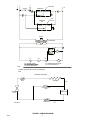
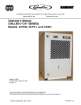
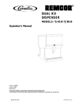
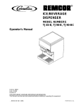
IMI CORNELIUS REMCOR INC g 500 REGENCY DRIVE g GLENDALE HEIGHTS, IL 60139–2268
Telephone (800) 551–4423
Facsimile (800) 519–4423
CHILLER
Models: CH1502A–LP
Operator’s Manual
Part No. 92074
July 24, 2002
Revision C
THIS DOCUMENT CONTAINS IMPORTANT INFORMATION
This Manual must be read and understood before installing or operating this equipment
IMI Cornelius Inc.; 1997–2002
PRINTED IN U.S.A
TABLE OF CONTENTS
Page
GENERAL DESCRIPTION . . . . . . . . . . . . . . . . . . . . . . . . . . . . . . . . . . . . . . . . . . . . . . . . . .
1
NAMING CONVENTION CH–1502–A . . . . . . . . . . . . . . . . . . . . . . . . . . . . . . . . . . . .
1
CONTROL SETTINGS . . . . . . . . . . . . . . . . . . . . . . . . . . . . . . . . . . . . . . . . . . . . . . . . .
2
INSTALLATION . . . . . . . . . . . . . . . . . . . . . . . . . . . . . . . . . . . . . . . . . . . . . . . . . . . . . . . . . . . .
3
LOCATION: . . . . . . . . . . . . . . . . . . . . . . . . . . . . . . . . . . . . . . . . . . . . . . . . . . . . . . . . . . .
3
ELECTRICAL: . . . . . . . . . . . . . . . . . . . . . . . . . . . . . . . . . . . . . . . . . . . . . . . . . . . . . . . . .
3
PLUMBING . . . . . . . . . . . . . . . . . . . . . . . . . . . . . . . . . . . . . . . . . . . . . . . . . . . . . . . . . . .
3
START–UP . . . . . . . . . . . . . . . . . . . . . . . . . . . . . . . . . . . . . . . . . . . . . . . . . . . . . . . . . . .
3
THERMOSTAT ADJUSTMENT . . . . . . . . . . . . . . . . . . . . . . . . . . . . . . . . . . . . . . . . . .
3
MAINTENANCE . . . . . . . . . . . . . . . . . . . . . . . . . . . . . . . . . . . . . . . . . . . . . . . . . . . . . . . . . . .
4
SERVICE . . . . . . . . . . . . . . . . . . . . . . . . . . . . . . . . . . . . . . . . . . . . . . . . . . . . . . . . . . . . .
4
REMOVING WRAPPER . . . . . . . . . . . . . . . . . . . . . . . . . . . . . . . . . . . . . . . . . . . . . . . 4
REPLACING THERMOSTAT . . . . . . . . . . . . . . . . . . . . . . . . . . . . . . . . . . . . . . . . . . . 4
ACCESS ELECTRICAL HOOK-UP . . . . . . . . . . . . . . . . . . . . . . . . . . . . . . . . . . . . . 5
FLUID RECOMMENDATIONS . . . . . . . . . . . . . . . . . . . . . . . . . . . . . . . . . . . . . . . . . . . . . . .
7
TROUBLESHOOTING . . . . . . . . . . . . . . . . . . . . . . . . . . . . . . . . . . . . . . . . . . . . . . . . . . . . . .
8
CHILLER DOES NOT OPERATE . . . . . . . . . . . . . . . . . . . . . . . . . . . . . . . . . . . . . . . .
8
UNIT OPERATES, BUT DOES NOT COOL. . . . . . . . . . . . . . . . . . . . . . . . . . . . . . . .
8
PART LIST . . . . . . . . . . . . . . . . . . . . . . . . . . . . . . . . . . . . . . . . . . . . . . . . . . . . . . . . . . . . . . . .
9
WARRANTY . . . . . . . . . . . . . . . . . . . . . . . . . . . . . . . . . . . . . . . . . . . . . . . . . . . . . . . . . . . . . .
10
LIST OF FIGURES
FIGURE 1. SAMPLE DATA PLATE FOR CH–1502–A . . . . . . . . . . . . . . . . . . . . . . .
4
FIGURE 2. WIRING DIAGRAM . . . . . . . . . . . . . . . . . . . . . . . . . . . . . . . . . . . . . . . . . .
6
LIST OF TABLES
TABLE 1. SPECIFICATION . . . . . . . . . . . . . . . . . . . . . . . . . . . . . . . . . . . . . . . . . . . . .
i
1
92074
GENERAL DESCRIPTION
This section gives the Unit description, theory of operation, and design data.
IMPORTANT: To the user of this manual – This manual is a guide for installing, operating, and maintaining this equipment. Refer to the Table of Contents for page location for detailed information pertaining to questions that arise during installation, operation, service, or maintenance of this equipment.
NAMING CONVENTION CH–1502–A
CH –
15 –
02 –
A–
W–
Denotes “CH” series chiller product.
Denotes 18,000 BTU/Hr. Nominal capacity. “1.5 TON”.
Voltage 230/3/60,
OD – 230/1/60
03 – 460/3/60
Denotes Air-Cooled Condenser
Denotes Water Cooled Condenser
The CH-1502-A model chiller from Remcor is designed to provide a continuous flow of clean cooling water at a
constant temperature.
The unit incorporates a refrigeration system with all necessary operating controls and safety devices. The housing is constructed of painted cold rolled steel panels, angles and a galvanized base with optional casters. All
flow requirements must be externally provided as there is no pump or tank provided with the CH-1502-A.
The chiller is designed to operate in a clean industrial or laboratory environment where ambient temperatures
range from 40 - 110_F. For applications which reject dirt or particles to the cooling fluid (i.e. EDM’s) it is necessary to filter the fluid before it enters the chiller (#20 mesh strainer, not supplied with unit). Fluid contaminated
with metal particles or dirt can clog the evaporator causing a decrease in capacity. There is an air filter installed
to keep the condenser fins clean. A dirty condenser leads to a decrease in capacity and higher than normal refrigerant pressure.
WARNING: Allow unit to sit in ambient for 24 hours before starting out of box. Never
operate the chiller with panels removed. Verify that air flow is unobstructed.
Table 1. SPECIFICATION
Cooling Capacity @ 70_F Ambient:
18,000 BTU/Hr.
Compressor:
Copeland Corporation CRA1-0150-TF5
1-1/2 Horsepower
Power Requirements:
230 Volts - 60 Hz, 7.3 Amps, 3 Phase
Condenser:
Total Heat Rejection to room
Air Cooled,
25,000 BTU/Hr.
Refrigerant:
HCFC–22 6.0 Lbs.
Temperature Control:
Set Point Range:
Temperature probe type:
Probe location:
Differential:
Eliwell digital display
40 – 100_F
Thermistor
Water inlet
$ 1_F
Dimensions:
Water Connections:
20”L x 20”W x 25”H
3/4” FPT stainless steel couplings
1
92074
CONTROL SETTINGS
92074
High Pressure Cut-Out:
350 PSI
Low Pressure Cut-Out:
44 PSI
Freeze Thermostat:
35_F (Probe on evaporator outlet)
Hot Gas By-Pass
This option feeds hot gas to the evaporator when the
water reaches set-point. The hot gas forces the water
temperature to increase 1_F quicker, which turns the
cooling back on.
2
INSTALLATION
LOCATION:
–
–
–
Indoors.
Adequately ventilated area.
(2 ft. of space on air intake and discharge sides).
Ambient temperature range (40_F – 100_F). (Optimum 80_F)
ELECTRICAL:
All wiring must conform to the National Electric Code and any applicable local codes. The Chiller must be
permanently wired by means of electrical conduit to a properly fused disconnect of proper amperage or
wired to a properly rated power cord and plugged into an outlet with the appropriate disconnect and amperage rating. The electrical junction box, located on top of the condenser fan shroud (must remove wrapper)
includes a four-terminal strip for power supply connections.
NOTE: The power harness currently supplied with the unit is not accepted within the National Electrical Code standards for permanent power hook-up. It is supplied by request of the customer only.
PLUMBING
–
–
–
–
–
Follow standard plumbing practices and codes.
3/4” FPT S.S. inlet/out couplings.
Use AT LEAST 3/4” I.D.. hose and fittings.
Install #20 mesh strainer in line. Clean monthly.
Insulate any lines susceptible to condensation or significant heat gain.
START–UP
Once the electrical and plumbing is hooked up, the unit is ready to operate (See Fluid Recommendations page).
By request, the CH–1502–A has no on/off switch so the unit is wired directly to the application that controls it.
When power is turned on to the Chiller it will operate continuously until either the operator turns it off or a safety
cut-out is triggered.
THERMOSTAT ADJUSTMENT
UP
_F
DOWN
SET
1. Push “SET” button on right side of display. The current set-point will be displayed.
2. While hold the “SET” button, push the “UP” or “DOWN” button until desired set-point is displayed.
3. Release “SET” button and display will show current Chiller inlet temperature.
3
92074
MAINTENANCE
CAUTION: Disconnect electrical power before performing any maintenance.
1. Keep condenser fins clean by blowing compressed air through the fins from the fan side as required to
eliminate any dirt or debris.
2. Drain and flush circulation system periodically to reduce the chance of restriction due to contaminants in
the water.
3. Clean strainer monthly.
SERVICE
When servicing the Chiller, it is important to note the information on the Data Plate located on the rear of the
unit. If necessary, call the service number on the Data Plate and have all information ready to give the technician on the telephone.
The Serial Number is required to order parts or make any warranty claims.
REMCOR PRODUCTS CO.
GLENDALE HEIGHTS. IL 60139
MODEL N O.
SERIAL NO.
CH1502–A
VOLTS
230V
3PH
G5
XXXX
AMPS
7.3A
60HZ
R–22 6 LBS.
FIGURE 1. SAMPLE DATA PLATE FOR CH–1502–A
Removing Wrapper
1. Disconnect power to unit.
2. Loosen all screws that secure wrapper, quantity 16.
3. Lift wrapper straight up.
Replacing Thermostat
1. Remove wrapper as stated above.
2. Note the location of all wires coming out of the back of thermostat.
3. Loosen screw terminals securing the wires at the rear of the thermostat and remove wires.
4. Loosen the mounting bracket with the phillips head screw in back of the thermostat.
5. Remove thermostat through front of panel.
6. Reverse for installation.
92074
4
Access Electrical Hook-Up
1. Remove wrapper.
2. Box is located on top of fan shroud.
3. Remove 2 screws in lid to access.
NOTE:
For any other service requirements on this unit, a Remcor Service Technician should be
contacted.
5
92074
L1
L3
SEE NOTE #1
HEATER
L2
COMPRESSOR
M1
M1
M1
SEE
NOTE #1
CONDENSER
FAN
230/460V
TRANSFORMER
24V
TC
6
7
1
5
8
LTC
LPC
SC
9
HPC
M1
NOTES
LTC: LOW TEMP CONTROL
LPC: LOW PRESSURE CONTROL
HPC: HIGH PRESSURE CONTROL
TC: ELIWELL TEMP CONTROL
M1: COMPRESSOR/FAN CONTACTOR
SC: HOT GAS SOLENOID COIL
1. THERMAL OVERLOADS ARE BUILT INTO THE COMPRESSOR
& FAN.
REFRIGERATION SCHEMATIC
SOLENOID
VALVE
CONDENSER
HPC
HOT GAS BY–PASS
VALVE
EXPANSION
VALVE
92218 REV. B
92074
COMPRESSOR
EVAPORATOR
FIGURE 2. WIRING DIAGRAM
6
LPC
FLUID RECOMMENDATION
Remcor Chillers are designed to operate with water to provide maximum performance for
temperatures of 40_F–100_F.
Distilled Water
Acceptable
De–Ionized Water
(1–5 MEG/OHMS)
Acceptable
De–Ionized Water
(5+MEG/OHMS)
Acceptable with Stainless Steel & PVC only
*No Copper or Brass
Propylene Glycol
(Lab & Industrial Grade)
Acceptable – 30% Glycol/70% Water
*For Applications with Temperatures below 40_F
Lab & Industrial Grade Ethylene Glycol
Acceptable – 30% Glycol/70% Water
*For Applications with Temperatures below 40_F
Mineral/Hydraulic Oils
(Viscosity<50 Centistrokes)
Acceptable
Ethylene Glycol
(Commercial/Automotive Antifreeze)
NOT Acceptable
*Silicate Rust Inhibitors in Automotive/Commercial Antifreeze will damage pump seals and
housing which lead to failure.
Acidic/Basic Solutions
(Above 8/Below 6 PH)
Not Acceptable
Mineral/Hydraulic Oils
(Viscosity>50 Centistrokes)
Not Acceptable
For questions regarding special or other fluids contact IMI Cornelius Remcor at
800–551–4423.
To Purchase Lab or Industrial Glycol contact:
Hubbard Hall
(800) 648–3412 – Dow Therm SR1 available in 5 gallon
IMI Cornelius
(800) 551–4423 – Part# 111521000 5 gallons
7
92074
TROUBLESHOOTING
IMPORTANT: Only qualified personnel should service internal components or electrical wiring.
WARNING: If repairs are to be made to a product system, remove quick disconnects from
the applicable product tank, then relieve the system pressure before proceeding. If repairs
are to be made to the CO2 system, stop dispensing, shut off the CO2 supply, then relieve the
system pressure before proceeding. If repairs are to be made to the refrigeration system, make sure
electrical power is disconnected from the unit.
Trouble
CHILLER DOES NOT
OPERATE
UNIT OPERATES, BUT DOES
NOT COOL.
92074
Probable Cause
Remedy
A.
Power not hooked up.
A.
Verify that the power is hooked up
properly.
B.
High Pressure Cut-Out has
tripped.
B.
Reset High Pressure Cut-Out
If refrigeration pressure gets
above 350 psi, this switch will
shut uint off. Follow procedure
above for removing wrapper.
Then locate the circular punch
out in the cover of the electrical
box. Press button inside this
punch out to reset the high
pressure control. Could result
from a dirty, clogged condenser
or too high of an ambient air
temperature.
C.
Low Pressure Cut-Out has
tripped.
C.
(Call Service) This has an
automatic reset. In order for
the low pressure safety to cut
out the unit, the low side
pressure must drop below the
settint (44psi). If this happens it
could mean a bad hot-gas
valve or bad low pressure
switch.
D.
Freeze Thermostat.
D.
If the freeze thermostat probe
located in the water discharge line
senses a temperature below 35_F
it will shut the unit off. It will
automatically reset when
temperature rises.
A.
Low refrigeration charge.
A.
Call service unit could have a
leak.
B.
Clogged condenser.
B.
Clean any dirt or debris from
condenser fins. Open the airway.
8
PART LIST
Item
No.
1
2
3
4
5
6
7
8
9
10
11
12
13
14
15
Part No.
15118
32386
32589
60506
60537
61139
61029
61051
61053
70480
32992
60687
31001
60501
60502
Description
Wrapper
Thermostat
Temperature Probe
Receiver
TX-Valve R22
Compressor
Condenser
Evaporator Assembly
Fan
Caster
Compressor Contactor
Sight Glass
Freeze Thermostat
High Pressure Control
Low Pressure Control
9
Qty.
1
1
1
1
1
1
1
1
1
4
1
1
1
1
1
92074
IMI CORNELIUS INC.
ONE CORNELIUS PLACE
ANOKA, MN. 55303–6234
TELEPHONE (800) 238–3600
FACSIMILE (763) 422–3232
TECH SVC 1-800-535-4240
WARRANTY
IMI Cornelius Inc. and Remcor Products Company warrants that all equipment and parts are free from defects
in material and workmanship under normal use and service. For a copy of the warranty applicable to your
Cornelius and or Remcor product, in your country, please write, fax or telephone the IMI Cornelius office nearest you. Please provide the equipment model number, serial number and the date of purchase.
IMI Cornelius Offices
AUSTRALIA D P.O. 210, D RIVERWOOD, D NSW 2210, AUSTRALIA D (61) 2 533 3122 D FAX (61) 2 534 2166
AUSTRIA D AM LANGEN FELDE 32 D A-1222 D VIENNA, AUSTRIA D (43) 1 233 520 D FAX (43) 1-2335-2930
BELGIUM D BOSKAPELLEI 122 D B-2930 BRAASCHAAT, BELGIUM D (32) 3 664 0552 D FAX (32) 3 665 2307
BRAZIL D RUA ITAOCARA 97 D TOMAS COELHO D RIO DE JANEIRO, BRAZIL D (55) 21 591 7150 D FAX (55) 21 593 1829
ENGLAND D TYTHING ROAD ALCESTER D WARWICKSHIRE, B49 6 EU, ENGLAND D (44) 789 763 101 D FAX (44) 789 763 644
FRANCE D 71 ROUTE DE ST. DENIS D F-95170 DEUIL LA BARRE D PARIS, FRANCE D (33) 1 34 28 6200 D FAX (33) 1 34 28 6201
GERMANY D CARL LEVERKUS STRASSE 15 D D-4018 LANGENFELD, GERMANY D (49) 2173 7930 D FAX (49) 2173 77 438
GREECE D 488 MESSOGION AVENUE D AGIA PARASKEVI D 153 42 D ATHENS, GREECE D (30) 1 600 1073 D FAX (30) 1 601 2491
HONG KONG D 1104 TAIKOTSUI CENTRE D 11-15 KOK CHEUNG ST D TAIKOKTSUE, HONG KONG D (852) 789 9882 D FAX (852) 391 6222
ITALY D VIA PELLIZZARI 11 D 1-20059 D VIMARCATE, ITALY D (39) 39 608 0817 D FAX (39) 39 608 0814
NEW ZEALAND D 20 LANSFORD CRES. D P.O. BOX 19-044 AVONDALE D AUCKLAND 7, NEW ZEALAND D (64) 9 8200 357 D FAX (64) 9 8200 361
SINGAPORE D 16 TUAS STREET D SINGAPORE 2263 D (65) 862 5542 D FAX (65) 862 5604
SPAIN D POLIGONO INDUSTRAIL D RIERA DEL FONOLLAR D E-08830 SANT BOI DE LLOBREGAT D BARCELONA, SPAIN D (34) 3 640 2839 D FAX (34) 3 654 3379
USA D ONE CORNELIUS PLACE D ANOKA, MINNESOTA D (763) 421-6120 D FAX (763) 422-3255
92074
10
IMI CORNELIUS INC.
Corporate Headquarters:
One Cornelius Place
Anoka, Minnesota 55303-6234
(763) 421-6120
(800) 238-3600