1
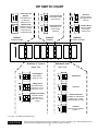
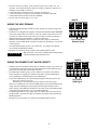
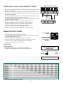
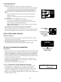
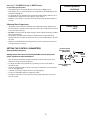
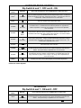
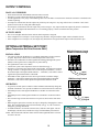
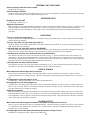
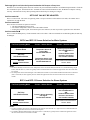
INSTALLATION/OPERATING INSTRUCTIONS
BCP-6 and BCP-12
Lead-Lag System for up to 12 Stages of Output
Operates as either an Outdoor Reset Control or as a Set
Point Control for Water Temperature or Steam Pressure
Table of Contents
Installation.........................................................................................................................pg. 2
Dip Switch Chart..........................................................................................................pg. 3
Initial Settings................................................................................................................pg. 8
Display Settings and Adjustments.............................................................................pg. 10
Operation...........................................................................................................................pg. 12
Outdoor Reset Control Settings................................................................................pg. 12
Set Point Control Settings.......................................................................................pg. 14
Lead Stage................................................................................................................pg. 15
Output Controls.........................................................................................................pg. 16
Optional External Set Point........................................................................................pg. 16
Interface Mode..........................................................................................................pg. 17
Heat Demand...............................................................................................................pg. 17
DHW Call....................................................................................................................pg. 17
Troubleshooting..............................................................................................................pg. 18
Sensor Selection.............................................................................................pg. 20
W A R N I N G This manual must only be used by a qualified heating installer/service
technician. Failure to comply could result in severe personal injury, death
or substantial property damage.
Part Number 550-141-695/1200
1
DEFINITIONS
WARNING
W A R N I N G Indicates presence of hazard
The Weil-McLain BCP-6/12 is strictly an operating
control; do not use as limit(s) or safety control(s).
Each boiler must have its own certified limit and
safety controls as required by codes. These controls
are the responsibility of the installing contractor. He
must verify proper operation and correct any safety
problems before installing the BCP-6/12.
C A U T I O N Indicates presence of hazard
Failure to follow all instructions in proper order can
cause severe personal injury, death or substantial
property damage. Read all instructions before
installing Weil-McLain BCP-6/12.
The following defined terms are used throughout this
manual to bring attention to the presence of hazards
of various risk levels, or to important information
concerning the life of the product.
which can cause severe personal
injury, death or substantial
property damage if ignored.
which will or can cause minor
personal injury or property
damage if ignored.
INSTALLATION
MOUNTING THE BCP-6/12
• Select a location near the equipment to be controlled.
• The surface should be flat, and be sufficiently wide and strong to hold the control
• Keep the control away from extreme heat or cold. Ambient operating temperature is
from 20 to 120°F.
• Remove the panel from the metal enclosure by removing the top center screw and
loosening the two screws at the bottom of the panel. Lift the panel out.
• Screw the enclosure to the surface through the mounting holes in the back of the
enclosure.
• Be sure to set the dip switches (below) before reinstalling the panel in the enclosure.
Mounting Holes
SETTING THE DIP SWITCHES
Dip switch chart is shown on opposite page
• The default dip switch settings are shown on the side chart.
• The dip switches are located on the rear of the BCP-6/12 board (the side of the board
without the metal front panel).
• The dip switch settings determine all of the following:
Control type - Outdoor Reset or Set Point
Stage type - On/Off or Lo/Hi/Lo
Rotation sequence - First On/Last Off or First On/First Off
Input type - Temperature, Pressure, Interface or External Set Point
System relay type - either Combustion Air Damper or System Pump
• After setting the dip switch, replace the BCP-6/12 board in the enclosure with the
three screws provided.
CAUTION
The dip switch must be set correctly. Carefully check the
details of the installation and determine the appropriate dip
switch settings before continuing on to the next steps.
2
Default Dip Switch Settings
#1
#2-3-4
#5
#6-7
#8
on
off
off
off
on
Pump
On/Off
24 Hour Rotation
Temperature
Reset
DIP SWITCH CHART
Combustion Air
Damper
SYSTEM relay is
on when any
OUTPUT is on *
ON
1
ON
1
ON
5
System Pump
SYSTEM relay is on
based on outside
temp and Heat
Demand terminal
ON
5
First On/First Off
First stage on is
the first stage
turned off
8
Outdoor Reset
Hydronic heating
control with
outdoor reset
ON
Switch 5
Rotation
Switch 1
System Output
8
Set Point
Set Point control
for temperature or
pressure
ON
First On/Last Off
Lead stage rotates
every 24 hours
Switch 8
Set Point or Reset
ON
1
2
3
4
5
Switches 2, 3, and 4
Stage Type
ON
3
2
3
4
4
2Stage Lo/Lo/Hi/Hi
On load increase
sequence on Lo
stages first, then Hi
stages
ON
2
3
Temperature
6
2 Stage Lo/Hi
On load increase
sequence Lo to Hi
then next Lo to Hi
8
ON
4
ON
7
Switches 6 and 7
Input Type
On/Off Stages
Each stage is
either on or off
2
6
7
ON
Pressure
6
7
ON
6
7
ON
External Set Point
Available for temperature
systems only, 4-20mA
signal changes Set Point
Interface
Sequencer is controlled
by BCP-4
6
7
* See page 7 for Warning and Instructions
CAUTION
If the dip switch is changed during operation, the BCP-6/12 will be completely reset. Wait until the BCP-6/12
restarts and then reprogram all the settings as shown on pages 10 and 11.
3
WIRING THE POWER INPUTS
POWER
NEUTRAL
• Bring the 120VAC 60Hz power wires through a bottom knock out of the enclosure.
Class 1 voltages must enter the enclosure through a different opening from any
Class 2 wiring.
• Connect the hot line to terminal marked LINE.
• Connect the neutral line to the terminal marked NEUTRAL.
• The green ground screw must be connected to earth ground.
LINE
MUST BE
CONNECTED
CONNECTING THE SENSORS
System Water Temperature
• The BCP-6/12 sensor is designed for immersion in a 3/8” ID well.
• Dip switches 6 and 7 must be OFF (unless using the External Set Point see pg. 16).
• Locate the sensor in the common header, where it will sense the output of all the
stages. If the sensor can not read the output of all the stages, it will not be able to
sequence properly.
• Temperature sensor wires can be extended up to 500’ by splicing with 18 gauge
shielded wire.
• Do not run sensor wire in conduit with line voltage.
• Temperature sensors have no polarity. Connect either wire from the sensor to
terminal 1 SENSOR.
• Connect the other sensor wire to terminal 2 COM.
• Connect the shield to terminal 3 SHIELD.
PRESSUR
4-20mA
TEMP
Sensor
Com
Shield
+
Sensor
1
2
3
4
5
Shield
To Temperature Sensor
in Common Header
INPUTS
INPUTS
Outdoor Sensor
• The BCP-6/12 can be connected to a sensor which reads outdoor temperature.
• If using the BCP-6/12 for Reset Control (dip switch 8 is ON), the Outdoor Sensor
must be installed.
• If using the BCP-6/12 for Set Point control (dip switch 8 is OFF), the Outdoor Sensor
is optional. If it is installed, it provides an Outdoor Starter (see pgs. 10-11).
• Locate the sensor in the shade on the north side of the building.
• Be sure the location is away from doors, windows, exhaust fans, vents, or other
possible heat sources.
• The sensor should be mounted at least 4 inches away from the building wall and
approximately 10 feet above ground level.
• Temperature sensor wires can be extended up to 500’ by splicing with 18 gauge
shielded wire.
• Do not run sensor wire in conduit with line voltage.
• Temperature sensors have no polarity. Connect either wire from the sensor to
terminal 11.
• Connect the other sensor wire to terminal 12.
• Connect the shield (when needed) to terminal 3 SHIELD. (Both sensor shields will
be connected to terminal 3.)
Steam Pressure (Set Point Controls ONLY)
HEAT
DEMAND
PRESSURE
4-20mA
Shield
+
Sensor
Com
3
4
5
6
Dry Contact Only Dry Contact Only
7
Shield
9
8
11
10
12
To Outdoor Sensor
located in shade
INPUTS
INPUTS
PRESSURE
4-20mA
Shield
+
Sensor
Com
3
4
5
6
RED
HEAT
DEMAND
DHW
Dry Contact Only Dry Contact Only
7
8
9
10
BLACK
Cut the Green,
White, and
Tube
• The BCP-6/12 is designed to be connected to a two wire 4-20mA pressure transducer with a range of 0-30 psi.
• Dip switch 6 must be ON and dip switches 7 and 8 must be OFF.
• Locate the sensor on the main supply header where it will sense the output of all the
stages. If the sensor can not read the output of all the stages, it will not be able to
sequence properly.
• Attach a 1/4” isolation pigtail to the header.
• Screw the pressure sensor to the pigtail. The sensor has 1/4” NPT threads.
• Pressure sensor wires can be extended up to 500’ by splicing with 18 gauge wire.
• Do not run sensor wire in conduit with line voltage.
4
OUT
DOOR
DHW
Connect
to 1/4" pigtail
• Pressure sensors have polarity. If the sensor has a green wire, a white wire, or a
clear tube, none of those should be connected. Simply cut them off. Only the red
and black wires should be connected.
• Connect the red wire from the pressure transducer to terminal 4 +.
• Connect the black wire from the pressure transducer to terminal 5 SENSOR.
• Connect shield (when needed) to terminal 3 SHIELD.
• Pressure sensor set point range is 0 to 15 psi.
INPUTS
INPUTS
SURE
mA
WIRING THE HEAT DEMAND
nsor
DHW
Dry Contact Only Dry Contact O
6
• If the HEAT DEMAND input terminals are open, the BCP-6/12 will not energize any
output stages.
• The BCP-6/12 is shipped with a jumper across the HEAT DEMAND inputs. DO NOT
remove this jumper unless you replace it with a dry contact switch which is closed
when heat is required in the system. This type of contact is usually provided by a
thermostat which activates the BCP-6/12 when it requires heat.
• When the HEAT DEMAND inputs are opened, all active stages are immediately
turned off. The SYSTEM output will remain on until the System Delay is over, then it
will also turn off.
• The Heat Demand signal must be a dry contact only. No voltage can be placed
across the HEAT DEMAND terminals.
• Bring the two wires from the dry contact to the terminals marked 7 and 8.
CAUTION
Com
HEAT
DEMAND
7
9
8
1
Dry Contact Heat
Demand Signal
DO NOT remove the factory installed Heat Demand jumper
without installing a Heat Demand switch.
WIRING THE DOMESTIC HOT WATER PRIORITY
• When the Domestic Hot Water (DHW) input is enabled by closing a dry contact, the
Calculated water temperature or the Set Point will change to 200°F and the decimal
point on the left-most digit on the display will flash.
• The DHW input will take priority over the outdoor reset function or the outdoor
starter temperature. Regardless of outdoor temperature, when the DHW input is
closed, the BCP-6/12 will lead/lag the boilers to hold 200°F.
• To provide a DHW priority for a System Pump output, the following must be true:
Dip switch 1 must be set to ON
On initial power up, the domestic priority must be selected (see pg. 9)
If these two conditions are met, when the DHW inputs are closed, the SYSTEM relay
output will open, disabling the system pump and allowing the domestic tank to
satisfy quickly. If the DHW call continues for more than 1 hour, the SYSTEM output
will resume normal operation (see pg. 17 for additional details).
• The DHW signal must be a dry contact only. No voltage can be placed across the
DHW terminals. Typically this input is provided by an aquastat which controls the
DHW temperature.
• Bring the two wires from the dry contact to the terminals marked 9 and 10.
5
INPUTS INPUTS
HEAT
DEMAND
OUT
DOOR
DHW
Dry Contact Only Dry Contact Only
7
8
9
10
11
Dry Contact
DHW Signal
12
BCP-6/12 Input Terminals
INTERFACING TO A BCP-4 OUTDOOR RESET CONTROL
INPUTS
PRESSURE
4-20mA
TEMP
• The BCP-4 is a commercial outdoor reset control for heat which can directly control
up to four output stages.
• The BCP-6/12 can be used to expand the number of output stages of this control
from 4 to 6 or 12. Check the I/O manual for the BCP-4 to be sure it is set up correctly
to interface to the BCP-6/12.
• When being used in the interface mode, the BCP-6/12 does not require a sensor. It
receives its staging information from the BCP-4 (see pg. 17).
• Dip switches 6 and 7 must be ON and dip switch 8 must be OFF for the BCP-6/12 to
recognize the staging information.
• Terminal 12 of the BCP-4 must be wired to BCP-6/12 input terminal 4.
• Terminal 13 of the BCP-4 must be wired to BCP-6/12 input terminal 5.
• Terminal 14 of the BCP-4 must be wired to BCP-6/12 input terminal 1.
• Terminal 15 of the BCP-4 must be wired to BCP-6/12 input terminal 2.
• Terminal 15 and 16 of the BCP-4 must be jumped together.
• Terminal 17 of the BCP-4 must be wired to BCP-6/12 input terminal 11.
HEAT
DEMAND
OU
DOO
DHW
Sensor
Com
Shield
+
Sensor
Com
1
2
3
4
5
6
7
8
9
9
10
11
12
13
14
15
16
17
Dry Contact Only Dry Contact Only
10
11
BCP-4 Output Terminals
WIRING THE OUTPUT STAGES
For non-active
stages
• Check all the relays are firmly seated in their sockets.
• Any output stage which is not used or does not have a relay must have its OFF/
AUTO/ON switch in the OFF position.
• Each output stage has one Normally Open (N.O.) relay contact.
• The N.O. contacts are dry contacts only. They do not source any voltage.
• Each N.O. contact is capable of switching 6A resistive at 120VAC.
• Total output of all stages must not exceed 15A.
STAGE 1
OFF
For stages which
are to be part of
the automatic
sequence
AUTO
ON
ON/OFF Units
(Refer to Chart Below)
• Each unit has one relay and one OUTPUT associated with it.
• Wire the N.O. relay contacts in series with the unit’s limit circuit.
Typical Limit Circuit for
ON/OFF Units
Unit
Output
NO
Limit
Circuit
C
Refer to Specific Boiler Wiring Diagram
OUTPUT
Output 1
Output 2
Output 3
Output 4
Output 5
Output 6
Output 7
Output 8
Output 9
Output 10
Output 11
Output 12
System
1
Unit 1
2
Unit 1
Unit 2
3
Unit 1
Unit 2
Unit 3
4
Unit 1
Unit 2
Unit 3
Unit 4
*
*
*
*
Number of ON/OFF Boiler Units
5
6
7
8
Unit 1
Unit 1
Unit 1
Unit 1
Unit 2
Unit 2
Unit 2
Unit 2
Unit 3
Unit 3
Unit 3
Unit 3
Unit 4
Unit 4
Unit 4
Unit 4
Unit 5
Unit 5
Unit 5
Unit 5
Unit 6
Unit 6
Unit 6
Unit 7
Unit 7
Unit 8
*
*
* System relay should always be installed.
6
*
*
9
Unit 1
Unit 2
Unit 3
Unit 4
Unit 5
Unit 6
Unit 7
Unit 8
Unit 9
10
Unit 1
Unit 2
Unit 3
Unit 4
Unit 5
Unit 6
Unit 7
Unit 8
Unit 9
Unit 10
11
Unit 1
Unit 2
Unit 3
Unit 4
Unit 5
Unit 6
Unit 7
Unit 8
Unit 9
Unit 10
Unit 11
*
*
*
12
Unit 1
Unit 2
Unit 3
Unit 4
Unit 5
Unit 6
Unit 7
Unit 8
Unit 9
Unit 10
Unit 11
Unit 12
*
2 Stage (Lo/Hi) Units
Typical Limit Circuit for
2 Stage Units
(Refer to Chart below)
• Each unit has two relays and two OUTPUTS associated with it.
• Check the chart for the Lo and Hi stage output positions.
• Connect the Lo N.O. relay contacts in series with the unit’s limit circuit.
• Connect the Hi N.O. relay contacts to the Hi control circuit.
Lo
Output
Hi
Output
NO
Limit
Circuit
C
NO
Hi
Circuit
C
Refer to Specific Boiler Wiring Diagram
OUTPUT
Output 1
Output 2
Output 3
Output 4
Output 5
Output 6
Output 7
Output 8
Output 9
Output 10
Output 11
Output 12
System
1
Lo 1
Hi 1
2
Lo 1
Hi 1
Lo 2
Hi 2
*
*
Number of Lo/Hi/Lo Boiler Units
3
4
Lo 1
Lo 1
Hi 1
Hi 1
Lo 2
Lo 2
Hi 2
Hi 2
Lo 3
Lo 3
Hi 3
Hi 3
Lo 4
Hi 4
*
*
5
Lo 1
Hi 1
Lo 2
Hi 2
Lo 3
Hi 3
Lo 4
Hi 4
Lo 5
Hi 5
*
6
Lo 1
Hi 1
Lo 2
Hi 2
Lo 3
Hi 3
Lo 4
Hi 4
Lo 5
Hi 5
Lo 6
Hi 6
*
* System relay should always be installed.
WIRING THE SYSTEM OUTPUT
Combustion Air Damper operation (Damper open prove switch must
be in boiler limit circuit)
WARNING
When using a combustion air damper, damper open prove
switch(es) are required and must be in the limit circuit of the
boilers. Failure to follow this can cause severe personal injury,
death, or substantial property damage.
• Dip switch 1 must be OFF.
• When the BCP-6/12 requires a stage to be active starting with all stages off the
SYSTEM relay is energized. Then the BCP-6/12 waits 30 seconds to give the damper
time to open.
• After the 30 second delay, the BCP-6/12 will bring on boiler stages as necessary to
hold either the computed water temperature or the set point.
• The SYSTEM output contact will remain active as long as any OUTPUT is active.
• After the last OUTPUT is turned off, the SYSTEM relay will remain energized for the
period of time set by the System Delay. If the System Delay is set to 0, the SYSTEM
relay will turn off immediately when the last stage turns off.
• The SYSTEM contact has a single pole double throw (SPDT) output.
• The SYSTEM contact can be used to control a damper or valve motor, or to energize
any equipment which should be active when any OUTPUT is active. It can also be
used as a signal to indicate when the BCP-6/12 has enabled one or more stages.
• The SPDT output is capable of switching 6A resistive at 120VAC.
7
SYSTEM
OUTPUT
System Pump operation
• Dip switch 1 must be ON.
• If an outdoor sensor is not connected or registers a fault condition:
- The SYSTEM output will be energized when any OUTPUT stage is energized.
- After the last OUTPUT is turned off, the SYSTEM output will remain energized for the period of time set by the System Delay and then turn off.
• When the control is set for “no DHW priority” (see pg. 9) and there is a call for
DHW:
- With the outdoor temperature below the Outdoor Starter, the SYSTEM
output will be active.
- Otherwise, the SYSTEM output will be off (after the System Delay has
expired).
• When the control is set for “DHW priority” (see pg. 9):
- For the first hour of a DHW call, the SYSTEM output will be off.
- After the first hour, when the outdoor temperature is below the Outdoor
Starter setting, the SYSTEM output will be active.
- When the outdoor temperature is above the Outdoor Starter, the SYSTEM
output will be off at all times.
• The SYSTEM contact has a single pole double throw (SPDT) output.
• The SPDT output is capable of switching 6A resistive at 120VAC.
• If the System Pump output has not been activated for 7 days (as might occur in the
summer), the SYSTEM relay will be energized for 15 seconds to exercise the pump.
SYSTEM
OUTPUT
For non-active
stages
OFF
For stages which
are to be part of
the automatic
sequence
INITIAL FRONT PANEL SETTINGS
Set before Power Up
• Each stage which is to be active (and has a relay installed) should have its OFF/
AUTO/ON switch in the AUTO position.
• Any stage which is not to be active (or any stages without output relays) should
have its OFF/AUTO/ON switch in the OFF position.
• Set the LEAD STAGE switch in the AUTO position for automatic rotation.
STAGE 1
AUTO
ON
LEAD STAGE
ROTATION
OFF
INCREMENT
AUTO
SETTING THE OPERATING PARAMETERS
For automatic lead
stage rotation
On Power Up
• Whenever the BCP-6/12 is powered up, it displays the software version number and
then the operating parameters. Each display will remain on the screen approximately
5 seconds. If the parameters are correct, there is no need to make any adjustments.
• There are no adjustable parameters when using the BCP-6/12 to control pressure.
• Once the parameters have been set for a particular application, they will be retained
in memory and will not need to be reset.
• Note that if you do change a parameter, you will need to reset all the settings.
• A parameter can only be changed in the start-up sequence. To restart, it is necessary to remove and reapply power.
• Set the parameters as described in sequence below:
°F or °C - Fahrenheit or Celsius Temperature Operation
• If the display shows °F then the BCP-6/12 will operate in Fahrenheit degrees.
• If the display shows °C then the BCP-6/12 will operate in Celsius degrees.
• To change the operating parameter, hold down the center button while pushing
either the UP or DOWN button to toggle between the displays of °F and °C.
• When the correct temperature display parameter is selected, release the buttons and
wait approximately 5 seconds.
8
Default Operation:
Fahrenheit
dno or d_P - NO DHW Priority or DHW Priority
(System Pump operation ONLY)
• If the display shows dno then the BCP-6/12 will not have a DHW priority.
• If the display shows d_P then the BCP-6/12 will disable the SYSTEM output for the
first hour of a DHW call.
• To change the priority, hold down the center button while pushing either the UP or
DOWN button to toggle between the displays of dno and d_P.
• When the correct priority is selected, release the buttons and wait approximately 5
seconds.
Minimum Water Temperature
•
The display will next show the minimum water temperature setting. The BCP-6/12
can not compute a calculated water temperature below this setting, and can not have
a set point value below this.
• DO NOT lower this below the default setting of 140°F without contacting your WeilMcLain representative.
• To change the minimum water temperature, hold down the center button while
pushing either the UP button to increase the value, or the DOWN button to decrease
the value.
• When the desired minimum water temperature is selected, release the buttons and
wait approximately 5 seconds.
Default Operation:
No Priority
Default Value:
140°F
Press to scroll
through control
parameters
SETTING THE CONTROL PARAMETERS
After the Startup Sequence
• After the startup routine has completed, the display will show the system water
temperature or the system steam pressure.
• To display the other control parameters, repeatedly press the center SELECT
SETTING button.
• Check the appropriate chart on the next two pages to find the list of control parameters for each application.
• A parameter can only be adjusted when it is being displayed.
• Use the UP and DOWN buttons to adjust the setting.
• The display will always revert back to the actual system temperature or pressure
after 30 seconds.
9
Press and
hold to
SELECT
adjust
SETTING
UP
Settings shown have been selected by Weil-McLain and will provide
proper operation for most installations.
DOWN
Control Parameter
display
OUTDOOR RESET CONTROL
Dip Switch 6 and 7 - OFF and 8 - ON
Press SELECT
Button
DISPLAY
Once *
Calculated
Twice *
Outdoor Temp
3 Times
4 Times
5 Times
6 Times
7 Times
8 Times
9 Times *
Fine Tune
Outdoor
Starter
Reset Ratio
Press and hold either the UP or DOWN button to adjust the value
This is the water temperature the BCP-6/12 will stage outputs to hold. It is based on
outdoor temperature, reset ratio, and the fine tune value. If ON is shown, there is a
sensor fault. If OFF is shown, there is no call for heat.
This is the outdoor sensor temperature value.
The Fine Tune moves the reset curves vertically up or down. For example, changing
the offset from 0 to -10 will decrease the water temperature 10° regardless of
outdoor temperature or the reset curve selected. The Fine Tune is adjustable
from -40 to 40°F.
When the outdoor temperature falls below the Outdoor Starter value, the BCP-6/12
will give heat. When the outdoor temperature is above the Outdoor Starter, the
Calculated value will be OFF and no stages will be activated. The Outdoor Starter
is adjustable from 40 to 100°F
The Reset Ratio controls the amount of heat which enters the heating system based
on the outdoor temperature. A higher numbered Reset Ratio will result in a higher
Calculated water temperature. See the chart on pg. 13 for the reset curves. The
Reset Ratio is adjustable from 1 to 12.
Reaction Time
The Reaction Time controls the minimum run time for a stage. It is adjustable from
half a minute (0.5) to 8.0 minutes.
System Delay
The System Delay controls how long the SYSTEM output will remain energized after
the last OUTPUT has been turned off or the outdoor temperature rises above the
Starter. The System Delay is adjustable from 0 to 30 minutes.
Purge Time
Default
The Purge Time should be set to the length of the unit's purge cycle. The Purge
Time will apply when any ON/OFF unit is activated. On multiple stage units, the
Purge Time will only apply to the Lo stages. The Purge Time is adjustable from
0.0 to 10.0 minutes.
The BCP-6/12 returns to the default display of actual water temperature.
* Value can not be adjusted
INTERFACE
Dip Switch 6 and 7 - ON and 8 - OFF
Press SELECT
Button
DISPLAY
Press and hold either the UP or DOWN button to adjust value
System Delay
The System Delay controls how long the SYSTEM output will remain energized after
the last OUTPUT has been turned off or the outdoor temperature rises above the
Starter. The System Delay is adjustable from 0 to 30 minutes.
Default
The BCP-6/12 returns to the default display of
Once
Twice
10
TEMPERATURE SET POINT CONTROL
Dip Switch 6 and 8 - OFF
Press SELECT
Button
Once
Twice *
3 Times
4 Times
5 Times
6 Times
7 Times **
7 (or 8) Times*
DISPLAY
Press and hold either the UP or DOWN button to adjust the value
Set Point
The Set Point is the temperature which the BCP-6/12 will stage units to hold. Note
that if you are using the External Set Point, you will not be able to change the Set
Point unless you adjust the 4-20mA input.
Outdoor Temp
This is the outdoor sensor temperature value. If the outdoor sensor is not used, the
outputs will automatically stage to hold the Set Point value.
Outdoor
Starter
When the outdoor temperature falls below the Outdoor Starter value, the BCP-6/12
will give heat. When the outdoor temperature is above the Outdoor Starter, the set
point value will be OFF and no stages will be activated. The Outdoor Starter
is adjustable from 40 to 100°F.
Reaction Time
The Reaction Time controls the minimum run time for a stage. It is adjustable from
half a minute (0.5) to 8.0 minutes.
System Delay
The System Delay controls how long the SYSTEM output will remain energized after
the last OUTPUT has been turned off or the outdoor temperature rises above the
Starter. The System Delay is adjustable from 0 to 30 minutes.
Purge Time
Offset
Default
The Purge Time should be set to the length of the unit's purge cycle. The Purge
Time will apply when any ON/OFF unit is activated. On multiple stage units, the
Purge Time will only apply to the Lo stages. The Purge Time is adjustable from
0.0 to 10.0 minutes.
The Programmed Offset fine tunes the External Set Point. With a known 4mA input,
the offset can be set to make the Set Point 110°F.
The BCP-6/12 returns to the default display of actual system water temperature.
* Value can not be adjusted
** Only available when using the external set point (Dip Switch 7 ON)
PRESSURE SET POINT CONTROL
Dip Switch 6 - ON , 7 and 8 - OFF
Press SELECT
Button
Once
Twice *
3 Times
4 Times
5 Times
6 Times
7 Times
8 Times *
DISPLAY
Set Point
Press and hold either the UP or DOWN button to adjust the value
The Set Point is the pressure which the BCP-6/12 will stage units to hold.
Outdoor Temp
This is the outdoor sensor temperature value. If the outdoor sensor is not used, the
outputs will automatically stage to hold the Set Point value.
Outdoor
Starter
When the outdoor temperature falls below the Outdoor Starter value, the BCP-6/12
will give heat. When the outdoor temperature is above the Outdoor Starter, the set
point value will be OFF and no stages will be activated. The Outdoor Starter
is adjustable from 40 to 100°F.
Reaction Time
The Reaction Time controls the minimum run time for a stage. It is adjustable from
half a minute (0.5) to 8.0 minutes.
System Delay
The System Delay controls how long the SYSTEM output will remain energized after
the last OUTPUT has been turned off or the outdoor temperature rises above the
Starter. The System Delay is adjustable from 0 to 30 minutes.
Purge Time
Offset
Default
The Purge Time should be set to the length of the unit's purge cycle. The Purge
Time will apply when any ON/OFF unit is activated. On multiple stage units, the
Purge Time will only apply to the Lo stages. The Purge Time is adjustable from
0.0 to 10.0 minutes.
The Programmed Offset fine tunes the pressure display. With a known 4mA input,
the offset can be used to calibrate the reading to 0.0psi.
The BCP-6/12 returns to the default display of actual system pressure.
11
OPERATION
OUTDOOR RESET DISPLAY SETTINGS (WATER)
CALCULATED
Select button pressed ONCE
• This is the water temperature the BCP-6/12 will stage units to hold. It is based on outdoor temperature and the Fine Tune and
Reset Ratio values (described below and on the following page).
• The Calculated water temperature can not be less than the minimum water temperature setting (see pg. 9).
• If either sensor is reading a fault condition, all stages will immediately turn on. The calculated water temperature display will
show ON to indicate this condition.
• If the outdoor temperature is above the Outdoor Starter, the BCP-6/12 will not activate stages. The calculated display will show
OFF to indicate this condition.
• A DHW call (see pg. 17) will override the Outdoor Starter. During a DHW call, the calculated temperature will be 200°F.
• The BCP-6/12 will either add stages, subtract stages, or maintain the same number of stages to hold the system temperature
around the Calculated temperature.
• The Calculated temperature is the average temperature the BCP-6/12 will maintain. The system can be expected to fluctuate above
and below the Calculated temperature. The size of the fluctuation depends on the number of stages, the size of each stage, the
system load, and the Reaction Time.
• The Calculated temperature is based on all the parameters described above. The Calculated value can not be changed by
pressing the UP or DOWN button while it is displayed.
OUTDOOR STARTER DEFAULT is OFF
Select button pressed 4 Times
• The Outdoor Starter sets at what outdoor temperature the BCP-6/12 will begin
heating.
• When the outdoor temperature is above the Outdoor Starter temperature, the
BCP-6/12 will not activate stages unless there is a DHW call. The Calculated
water temperature will read OFF.
• The Outdoor Starter has a built in 2°F differential.
• When the outdoor temperature drops below the Outdoor Starter temperature
minus the 2°F differential, the BCP-6/12 will compute the Calculated water
temperature and sequence stages to hold that temperature.
• If the building is too cold before the system starts, raise the Outdoor Starter
temperature.
• The Outdoor Starter temperature can be set from 40 to 100°F.
12
With a 0° Fine
Tune, the ratio
curves begin at
100° Water
Temperature.
Water Temperature
DEFAULT is 0°
With a -20° Fine
Tune, the ratio
curves begin at
80° Water
Temperature.
1:1
120
110
4:1
70
60
50
40
Outdoor Temperature
1:3
110
1:1
100
90
80
With a +20° Fine
Tune, the ratio
curves begin at
120° Water
Temperature.
1:3
130
100
Water Temperature
Select button pressed 3 Times
• The Fine Tune value moves the starting point of the Reset Ratio curves (see
charts on the right).
• Therefore, any change made to the Fine Tune will immediately change the value of
the Calculated water temperature by the same amount.
• For example, if the Calculated water temperature were 150°F based on the specific
outdoor temperature and Reset Ratio, then increasing the Fine Tune from 0°F to
10°F would increase the Calculated water temperature to 160°F.
• In a new installation, start with a Fine Tune value of 0°.
• Adjust the Fine Tune value in mild weather. If the ambient indoor temperatures
are warm in the warm weather, decrease the Fine Tune. If the ambient building
temperatures are cold in the mild weather, increase the Fine Tune.
• The rule of thumb for baseboard radiation is to change the Fine Tune by 4° for
every degree you wish to change the building temperatures. For radiant heat
applications, change the Fine Tune by 1° or 2° for every degree you wish to
change the building temperature.
• The Fine Tune can be set from -40 to 40°F.
Water Temperature
FINE TUNE
4:1
70
60
50
40
Outdoor Temperature
150
1:3
1:1
140
130
120
4:1
70
60
50
40
Outdoor Temperature
DEFAULT is 7
Select button pressed 5 Times
• The Reset Ratio controls how much heat will be added based on outdoor temperature. The Reset Ratios are shown as Outdoor Temperature:Water Temperature.
• A 1:1 Reset Ratio signifies for each degree it gets colder outside, the Calculated
water temperature will raise 1 degree.
• The other Reset Ratios available are shown on the right.
• The Reset Ratio curves start at 70°F. At 70°F the BCP-6/12 will require 100°F water.
Note that this is not the point where the BCP-6/12 will begin giving heat. That point
is determined by the Outdoor Starter. Also note that this starting point can be
changed by adjusting the Fine Tune as shown on the previous page.
• For new installations with standard baseboard heating, begin with a Reset Ratio
curve of 7.
• For new installations with radiant heat, begin with a Reset Ratio curve of 4 or 5.
• Adjust the Reset Ratio value in cold weather. If the ambient indoor temperatures
are cold in the cold weather, pick the next higher Reset Ratio (that is, go from 7 to 8).
If the ambient building temperatures are warm in the cold weather, pick the next
lower Reset Ratio.
• After adjusting the Reset Ratio curve, wait at least 24 hours before making another
adjustment.
• The Reset Ratio can be set from 1 to 12.
REACTION TIME
DEFAULT is 2.0
220
1:4 1:3
1:2
1:1.5
12 11
10
9
8 1:1.25
210
Water Temperature (in °F)
RESET RATIO
200
190
7 1:1
180
170
6 1.25:1
160
5 1.5:1
150
4 2:1
140
120
3 3:1
2 4:1
110
1 8:1
130
100
70
60
50
40
30
20
10
0
-10 -20
Outdoor Temperature (in °F)
CAUTION
The BCP-6/12 will not generate a
Calculated water temperature below
the minimum water temperature
setting.
Select button pressed 6 Times
• The Reaction Time controls the minimum run time for any stage.
• When a stage has been added, that stage can not be turned off until at least half the Reaction Time has elapsed.
• The Reaction Time must be at least as long as the time it takes for a newly activated stage to start affecting the system. If the
Reaction Time is shorter than this, the BCP-6/12 may activate additional stages before it can see the impact of each stage. (Note
that it is not necessary to include the purge cycle time for a new stage, as that is set on the Purge Time which is described below).
• For cast iron boilers, it is recommended to start with a Reaction Time of 5.0 minutes.
• If the system temperature tends to fluctuate rapidly above and below the Calculated water temperature, the Reaction Time may be
set too short.
• If the system temperature tends to remain always below the Calculated water temperature, the Reaction Time may be set too long.
• When making a change to the Reaction Time, wait at least 5 reaction times before making another change. The system will need
time to settle out.
• The Reaction Time can be set from half a minute (0.5) to eight minutes (8.0).
SYSTEM DELAY
DEFAULT is 10
Select button pressed 7 Times
• If the SYSTEM output is configured for Combustion Air Damper operation, the SYSTEM output will be active when any OUTPUT
is active.
• If the SYSTEM output is configured for System Pump operation, the SYSTEM output will be active when the outdoor temperature
is below the outdoor starter and there is a call for Heat Demand (and there is no call for DHW with Domestic Priority).
• Whenever the BCP-6/12 determines the SYSTEM output needs to be disabled, the SYSTEM output will remain energized for the
period of time set by the System Delay.
• The System Delay can be set from 0 to 30 minutes.
PURGE TIME
DEFAULT is 0
Select button pressed 8 Times
• Many units must go through a purge cycle before they are brought on line and begin heating.
• The Purge Time should be set to the time of the unit’s purge cycle.
• The Purge Time applies to every stage with ON/OFF units.
• The Purge Time applies only to the Lo stages of multiple stage units.
• When an ON/OFF stage, or a Lo stage, is turned on, the BCP-6/12 will begin counting down the Purge Time. When the Purge
Time has elapsed, then the BCP-6/12 will begin counting down the Reaction Time. Therefore, if the Purge Time applies to a
particular stage, the minimum run time of that stage is the Purge Time plus half a Reaction Time.
• The Purge Time can be set from 0 minutes (0.0) to 10 minutes (10.0).
13
SET POINT DISPLAY SETTINGS (WATER or STEAM)
SET POINT
Select button pressed ONCE
• The Set Point is the temperature or pressure value the BCP-6/12 will use to control the system.
• The BCP-6/12 will either add stages, subtract stages, or maintain the same number of stages to hold the system temperature or
pressure around the Set Point.
• The Set Point is the average temperature or pressure the BCP-6/12 will maintain. The system can be expected to fluctuate above
and below the Set Point. The size of the fluctuation depends on the number of stages, the size of each stage, the system load,
and the Reaction Time (below).
• If it is a temperature system and the External Set Point is being used, the Set Point will vary with the 4-20mA input (see pg. 16). In
this case, the Set Point can not be adjusted by using the buttons.
OUTDOOR STARTER
DEFAULT is OFF
Select button pressed 3 Times
• The Outdoor Starter sets the temperature at which the BCP-6/12 will begin heating.
• When the outdoor temperature is above the Outdoor Starter temperature, the BCP-6/12 will not activate stages unless there is a
DHW call. The Calculated water temperature will read OFF.
• The Outdoor Starter has a built in 2°F differential.
• When the outdoor temperature drops below the Outdoor Starter temperature minus the 2°F differential, the BCP-6/12 will compute
the Calculated water temperature and sequence stages to hold that temperature as long as there is a call for Heat Demand.
• If the building is too cold before the system starts, raise the outdoor starter temperature.
• The Outdoor Starter temperature can be set from 40 to 100°F.
REACTION TIME
DEFAULT is 2.0
Select button pressed 4 Times
• The Reaction Time controls the minimum run time for any stage.
• When a stage has been added, that stage can not be turned off until at least half the Reaction Time has elapsed.
• The Reaction Time must be at least as long as the time it takes for a newly activated stage to start affecting the system. If the
Reaction Time is shorter than this, the BCP-6/12 may activate additional stages before it can see the impact of each stage. (Note
that it is not necessary to include the purge cycle time for a new stage, as that is set on the Purge Time which is described below).
• For cast iron boilers, it is recommended to start with a Reaction Time of 5.0 minutes.
• If the system tends to fluctuate rapidly above and below the Set Point, the Reaction Time may be set too short.
• If the system tends to remain always below the Set Point, the Reaction Time may be set too long.
• When making a change to the Reaction Time, wait at least 5 reaction times before making another change. The system will need
time to settle out.
• The Reaction Time can be set from half a minute (0.5) to eight minutes (8.0).
SYSTEM DELAY DEFAULT is 10
Select button pressed 5 Times
• If the SYSTEM output is configured for Combustion Air Damper operation, the SYSTEM output will be active when any OUTPUT
is active.
• If the SYSTEM output is configured for System Pump operation, the SYSTEM output will be active when the outdoor temperature
is below the outdoor starter and there is a call for Heat Demand (and there is no call for DHW with Domestic Priority).
• Whenever the BCP-6/12 determines the SYSTEM output needs to be disabled, the SYSTEM output will remain energized for the
period of time set by the System Delay.
• The System Delay can be set from 0 to 30 minutes.
14
PURGE TIME
DEFAULT is 0
Select button pressed 6 Times
• Many units must go through a purge cycle before they are brought on line and can begin generating heat or cooling.
• The Purge Time should be set to the time of the unit’s purge cycle.
• The Purge Time applies to every stage with ON/OFF units.
• The Purge Time applies only to the Lo stages of multiple stage units.
• When an ON/OFF stage, or a Lo stage, is turned on, the BCP-6/12 will begin counting down the Purge Time. When the Purge
Time has elapsed, then the BCP-6/12 will begin counting down the Reaction Time. Therefore, if the Purge Time applies to a
particular stage, the minimum run time of that stage is the Purge Time plus half a Reaction Time.
• The Purge Time can be set from 0 minutes (0.0) to 10 minutes (10.0).
LEAD STAGE
LEAD STAGE LIGHTS
• The row of green lights marked LEAD indicate which stage is currently the Lead Stage.
• The stage with the green light on is currently the Lead Stage.
• Only one stage can be the Lead Stage at any given time. The Lead Stage is always the first stage brought on when there is a call
for output.
LEAD STAGE SWITCH
• The LEAD STAGE switch controls the rotation of the stages.
• A unit can not be lead if any of its OFF/AUTO/ON switches is not set to AUTO. Any unit which has a one or more stages
switched ON or OFF is not considered as part of the rotation.
• Only the Lo stages of lo/hi boilers can be selected to be lead.
• If the LEAD STAGE switch is in the OFF position, whichever stage is presently the Lead Stage will remain the Lead Stage until
power is lost (then it will revert back to the first available stage).
• To change the current lead stage, press the LEAD STAGE switch to the INCREMENT position and then release it. The green
light indicating Lead Stage will increment to the next available stage.
• To automatically rotate the lead stage, switch the LEAD STAGE switch to the AUTO position (the different types of rotation are
described below).
FIRST ON/LAST OFF ROTATION
•
•
•
•
•
•
•
For this type of rotation, dip switch 5 must be in the OFF position.
On power up, or any time the BCP-6/12 loses power, the Lead Stage will be the first possible lead stage (as described above).
After the first 12 hours of power, the Lead Stage will change to the next possible stage.
Subsequently, every 24 hours, the Lead Stage will change to the next possible stage.
The Lead Stage will always be the first stage brought on when there is a call for output.
As more output is needed, additional stages are added.
When less output is needed, the additional stages are turned off in the reverse order of how they were added. For instance, if the
stages were added in the sequence 1, 2, and 3, then they will be turned off in the sequence 3, 2, and finally 1.
FIRST ON/FIRST OFF ROTATION
• For this type of rotation, dip switch 5 must be in the ON position.
• On power up, or any time the BCP-6/12 loses power, the Lead Stage will be the first possible stage (as described in Lead Stage
Switch).
• The Lead Stage will always be the first stage brought on when there is a call for output.
• As more output is needed, additional stages are added.
• When less output is needed, the Lead Stage will be the first stage turned off. The green light indicating lead stage will then
switch to the next available stage. For instance, if the stages were added in the sequence 1, 2, and 3, then they will be turned off
in the sequence 1, 2, and finally 3. The lead stage would now be 4 when more output is needed.
15
OUTPUT CONTROLS
MANUAL OVERRIDES
• Each OUTPUT and the SYSTEM has an OFF/AUTO/ON switch.
• The BCP-6/12 only controls units which are switched to AUTO.
• In lo/hi applications, if any stage of the multistage unit is not switched to AUTO, then the whole unit will not be considered in the
normal sequencing.
• If an output is switched ON, then the output relay will always be energized. Any stage will run on its own limits. This switch
position can be used for testing individual outputs.
• If an output is switched OFF, then the output relay will not energize. Any output without an output relay must be switched to
OFF. Also, if an output needs maintenance or is not working properly, it can be switched to the OFF position.
OUTPUT LIGHTS
• The row of red lights marked ACTIVE indicate which outputs are energized.
• If the red light next to an output is on, the output relay should be energized and the output contacts should be closed.
• If the red light next to an output is off, the output relay should not be energized and the output contacts should be open.
OPTIONAL EXTERNAL SET POINT
(Water Temperature Set Point Controls ONLY)
BCP-6/12 Sources Current
24VDC Excitation Voltage
INSTALLATION
• Can only be used when the BCP-6/12 is regulating temperature to hold a constant
set point. Dip switch 6 and 8 must be OFF and dip switch 7 must be ON.
• The BCP-6/12 can then take a 4-20mA signal from an Energy Management System
(EMS) or other signal source to change the set point remotely.
• The signal must be a two-wire 4-20mA.
• Connect the system water temperature sensor as described on pg. 4.
• The BCP-6/12 can source the current for the 4-20mA input. It provides an excitation
voltage of 24VDC. If using the BCP-6/12 to source the power, attach the (+) side of
the 4-20mA input to the input terminal marked 4 +. Attach the (-) side of the 4-20mA
signal to the input terminal marked 5 SENSOR.
• If the EMS or other signal sources the current (provides the excitation voltage),
attach the (+) side of the 4-20mA input to the input terminal marked 5 SENSOR.
Attach the (-) side of the 4-20mA input to the input terminal marked 6 COM.
OPERATION
• A typical use for this option would be to allow an EMS to automatically change the
Set Point of the BCP-6/12 to provide an outdoor air reset function for hot water heat.
• If the EMS provides a 4mA signal to the BCP-6/12, the BCP-6/12 Set Point will be
110°F.
• If the EMS provides a 20mA signal to the BCP-6/12, the BCP-6/12 Set Point will be
210°F.
• The Set Point range is linear between these two point as shown on the chart at the
right.
• When using this option, the Set Point can only be changed by changing the 4-20mA
input. The Set Point display will be shown normally (see pg. 11), but it can not be
changed by pushing the buttons.
• To disable the BCP-6/12 from the external source, send out a 0mA signal. The Set
Point display will show OFF, and all active stages will immediately be turned off.
NOTE: The Set Point will read OFF whenever the 4-20mA signal falls below 3.9mA or
rises above 20.1mA.
16
PRESSURE
4-20mA
+
Sensor
Com
4
5
6
(-) Input
(+) Signal
EMS Sourcing Current
PRESSURE
4-20mA
+
Sensor
Com
4
5
6
(-) Input
(+) Signal
4-20mA Input
4
6
8
10
12
14
16
18
20
Set Point
110°F
122°F
135°F
147°F
160°F
172°F
185°F
197°F
210°F
INTERFACE MODE
•
•
•
•
The BCP-6/12 can be connected to the BCP-4 for commercial hot water heat applications.
The BCP-4 can directly control up to 4 output stages.
The BCP-6/12 can be used to expand the number of output stages from 4 to 6 or 12.
When in the Interface mode, the BCP-6/12 determines when heat is needed, how much heat is needed, and how often stages will
be added or subtracted. Therefore, if the reset control is not set up properly, the BCP-6/12 will not output correctly. Check the
I/O manual for the reset control to be sure it is set up properly to interface to the BCP-6/12.
• The BCP-6/12 gets only four pieces of information from the reset control:
Add
Add the next available stage
Subtract
Subtract a stage
Rotate
If you have selected First On/Last Off rotation, the reset control will rotate the Lead Stage at 2 am every day. If
you have selected First On/First Off rotation, this signal will be ignored.
Reset
Turns off any active stages
• When in the Interface mode, the BCP-6/12 display reads INF. The only parameter which can be set is the System Delay.
• For wiring an Interface, see pg. 6.
HEAT DEMAND
• When the HEAT DEMAND input terminals are closed, the BCP-6/12 will not energize any stages unless there is a DHW call (see
below).
• The BCP-6/12 comes equipped with a factory installed jumper across the HEAT DEMAND terminals. DO NOT remove this jumper
unless it is being replaced by a dry contact switch.
• This input would typically be provided by a thermostat. When the thermostat is satisfied, there is no need for heat. When the
thermostat requires heat, the BCP-6/12 will activate and stage the OUTPUTs to hold the required set point.
• This input can also be used as a remote stop/start for the BCP-6/12.
• When the HEAT DEMAND terminals are first opened, all active OUTPUTs will immediately turn off. However, the SYSTEM will
remain activated for the period of time set by the System Delay.
• For wiring the Heat Demand, see pg. 5.
CAUTION
DO NOT remove the factory installed Heat Demand jumper without installing a Heat Demand switch.
DHW CALL (Temperature Controls ONLY)
• When the DHW terminals are closed, the BCP-6/12 Set Point immediately changes to 200°F. This will happen regardless of
outdoor temperature, the status of the Heat Demand input, or the External Set Point (if that function is being used).
• Typically the DHW input is wired to an aquastat which monitors the domestic hot water temperature. When the aquastat calls for
heat, it will close the DHW input terminals.
• If the System Output is configured for Combustion Air Damper operation, the SYSTEM relay output will be closed when any
OUTPUT is activated to hold the 200°F set point.
• If the System Output is configured for System Pump operation without DHW priority (see pg. 9) then the SYSTEM relay will be
closed whenever the outdoor temperature is below the Outdoor Starter and there is a call for Heat Demand regardless of the DHW
input status.
• If the System Output is configured for System Pump operation with DHW priority (see pg. 9) then:
For the first hour of a DHW call, the SYSTEM relay output will be open
After the hour had elapsed, the SYSTEM relay output will revert to its normal mode of operation (that is either on or off
depending on outdoor temperature and the status of the Heat Demand input)
• For wiring the DHW input, see pg. 5.
17
TROUBLESHOOTING
No Display, or Display of 888
Check the 120VAC power input to the BCP-6/12. Turn power to the panel off and
back on.
TEMPERATURE INPUTS
Display shows OPN
First check the dip switch (see pg. 3) to be sure the BCP-6/12 is configured to read a
temperature input. If the dip switch is correct, then the BCP-6/12 does not register
that a sensor is connected. Check that the wires from the sensor are continuous to
the BCP-6/12. Then follow the procedure for Incorrect Temperature Display.
Display shows SHT
The BCP-6/12 sees a short across the input terminals. Remove the wires from the
TEMP (1 & 2) inputs. The display should change to read OPN. If it doesn’t, the
BCP-6/12 may be damaged.
Display shows an Incorrect Temperature Display
Remove the wires from the TEMP (1 and 2) inputs. The display should change to
read OPN. If it doesn’t, the BCP-6/12 may be damaged. Take an ohm reading across
the detached sensor wires. The ohm reading should correspond to the chart at
right. If it doesn’t, the sensor may be damaged.
Outdoor Temperature Display shows OPN
Check the wires from the outdoor sensor are continuous to the BCP-6/12. Then
follow the procedure for Incorrect Outdoor Temperature Display.
Outdoor Temperature Display shows SHT
The BCP-6/12 sees a short across the input terminals. Remove the wires from the
OUTDOOR (11 & 12) inputs. The display should change to read OPN. If it doesn’t,
the BCP-6/12 may be damaged.
Outdoor Temperature Display shows an Incorrect Reading
Remove the wires from the OUTDOOR (11 & 12) inputs. The outdoor temperature
display should change to read OPN. If it doesn’t, the BCP-6/12 may be damaged.
Take an ohm reading across the detached sensor wires. The ohm reading should
correspond to the chart on the right. If it doesn’t, the sensor may be damaged.
PRESSURE INPUTS
Display shows OPN
First check the dip switch (see pg. 3) to be sure the BCP-6/12 is configured to read a
pressure input. If the dip switch is correct, then the BCP-6/12 does not register that
a sensor is connected. Check the wires from the sensor are continuous to the BCP6/12 and the polarity is correct (see pg. 4). Then follow the procedure for Incorrect
Pressure Display.
Display shows SHT
The BCP-6/12 sees a short across the input terminals. Remove the wires from the
PRESSURE (4 & 5) inputs. The display should change to read OPN. If it doesn’t,
the BCP-6/12 may be damaged.
Incorrect Pressure Display
Remove the wires from input terminals + and SENSOR (4 & 5). Check for 25VDC
across the two terminals. If it is not present, the BCP-6/12 may be damaged. Otherwise replace the black sensor wire to terminal SENSOR (5). Put an ampmeter in
series by connecting the (-) side of the meter to the detached red wire from the
sensor, and the (+) side of the meter to the + (4) input terminal. The mA reading
should correspond to the chart on the right. If it doesn’t, the sensor may be
damaged.
18
Temperature Sensor
Chart
TEMPERATURE
(in degrees F)
0
10
20
25
30
35
40
45
50
55
60
70
80
90
100
110
120
130
140
150
160
170
180
190
200
VALUE
(in Ohms)
42683
31215
23089
19939
17264
14985
13040
11374
9944
8714
7653
5941
4649
3667
2914
2332
1879
1524
1243
1021
842
699
583
489
412
Pressure Sensor
Chart
Input
mA
4
4.56
5.06
5.6
6.13
6.6
7.2
8.8
10.4
12
13.6
15.2
16.8
18.4
20
Pressure
(PSI)
0
1
2
3
4
5
6
9
12
15
18
21
24
27
30
EXTERNAL SET POINT INPUT
Set Point changes when the knob is rotated
Check the dip switch (pg. 3).
Set Point always reads OFF
Check the wiring is appropriate for the application (see pg. 16). Then use an ampmeter to measure the 4-20mA input. If the input
is below 3.9mA or above 20.1mA, the Set Point will always be OFF.
INTERFACE INPUT
Display does not show INF
Check the dip switch (see pg. 3).
Stages do not sequence
Make sure that any stages which should be sequenced have their OFF/AUTO/ON switch in the AUTO position. Check the wiring
between the BCP-6/12 and the BCP-4 as shown on pg. 6. Check for continuity on each wire. Make sure the metal jumper is
between terminals 15 & 16 of the BCP-4. If the wiring is correct, check the manual for the BCP-4 for further troubleshooting
procedures.
LEAD STAGE
There is no green lead stage light on
Check the 120VAC power input to the BCP-6/12. Turn power to the panel off and back on. If one lead stage LED does not light,
then the unit may be damaged.
There are more than one green lead stage lights on
Check the 120VAC power input to the BCP-6/12. Turn power to the panel off and back on. If only one lead stage LED does not
light, then the unit may be damaged.
Lead Stage does not rotate when switch to INCREMENT
Only units which have (all stages of) their OFF/AUTO/ON switches in the AUTO position and which are designated as Unit or Lo
stages can be lead. If there is more than one stage which meets this criteria, the BCP-6/12 may be damaged.
Lead Stage does not rotate every 24 hours (First On/Last Off Rotation)
First check the dip switch is set up for First On/Last Off rotation (see pg. 3). Then check the lead stage can be rotated as described above. Then check the INCREMENT/OFF/AUTO switch is in the AUTO position. In the AUTO position, the lead stage
should rotate among the possible lead stages every 12 hours after the unit is first powered up, and then every 24 hours after that.
If the panel loses power, the lead stage and the rotation timer will be reset.
Lead Stage does not rotate First On/First Off
First check the dip switch is set up for First On/First Off rotation (see pg. 3). Then check the lead stage can be rotated as described above. Then check the INCREMENT/OFF/AUTO switch is in the AUTO position.
OUTPUT STAGES
When switched to ON, the stage does not come on
Remove any wires attached to the BCP-6/12 OUTPUT terminals. Check for continuity across the N.O. contacts. If there is
continuity, the BCP-6/12 is working correctly. Check the wiring and the stage being energized to determine why it is not operating.
Red stage light is lit, but the stage is not on
The BCP-6/12 is calling for this stage to be on. Follow the procedure above.
Red stage light is not lit, but the stage is on
The BCP-6/12 is not calling for this stage. Remove any wires attached to the BCP-6/12 output. Check for continuity across the
BCP-6/12 N.O. contacts. If there is no continuity, the BCP-6/12 output is working correctly. Check the unit for any other operating controls which may be causing it to energize.
Stages don’t sequence
Make sure that the red output lights on the BCP-6/12 correspond to the stages operation. If they don’t, follow the steps above.
Then check the dip switches (pg. 3) to be sure they are set correctly for your application. Check the Set Point or the Calculated
water temperature is what is expected. Check the OFF/AUTO/ON stage switches. Only units which have all stages switched to
AUTO will be part of the automatic sequencing.
SYSTEM OUTPUT
When switched to ON, the System Combustion Air Damper or Pump does not come on
Remove any wires attached to the BCP-6/12 SYSTEM terminals. Check for continuity across the N.O. contacts. Then check the
N.C. terminals are open. If both are true, the BCP-6/12 is working correctly. Check the wiring and the unit being energized to
determine why it is not operating.
Red stage light is lit, but the System Combustion Air Damper or Pump is not on
The BCP-6/12 is calling for the unit. Follow the procedure above.
19
Red stage light is not lit, but the System Combustion Air Damper or Pump is on
The BCP-6/12 is not calling for the unit to run. Remove any wires attached to the BCP-6/12 SYSTEM output terminals. Check the
N.O. terminals are open. Then check the N.C. terminals are closed. If both conditions are true, the BCP-6/12 output is working
correctly. Check the unit for any other operating controls which may be causing it to energize.
SET POINT CAN NOT BE ADJUSTED
Set Point reads ON
There is a sensor fault. The sensor is registering either it is open or shorted. In the outdoor reset mode, the outdoor sensor
could be the one with the fault.
Set Point reads OFF
There are three reasons the set point will read off:
1. The HEAT DEMAND contact is open
2. The outdoor temperature sensor is above the Outdoor Starter
3. If using the external set point, the 4-20mA input is not connected, or does not provide a signal between 4 and 20mA
Set Point reads 200°°F
There is a call for DHW priority. Check terminals 9 and 10 for a short. If the two terminals are not shorted together, the unit may
be damaged.
BCP-6 and BCP-12 Sensor Selection for Water Systems
For Each Operating Mode
Choose 1 Indoor Sensor
Outdoor Reset
Temperature Sensor &
Control Well
Use Part #389-900-175
Choose 1 Outdoor Sensor
.
Set Point
with Outdoor Starter
Set Point
without Outdoor Starter
-ORTemperature Sensor with
Housing and Control Well
Use Part #389-900-176
Mounting Clip and Sensor
Use Part #389-900-177
-OROutdoor Weather Head
Enclosure and Sensor
Use Part #511-624-640
None used for Set Point without
Outdoor Starter
Notes:
1. The most commonly used sensors are the Temperature Sensor & Control Well (P/N 389-900-175) and the Mounting Clip &
Sensor (P/N 389-900-177). These are typically used for residential and semi-commercial applications where the sensor leads
are exposed.
2. The Temperature Sensor with Housing & Control Well (P/N 389-900-176) and Outdoor Weather Head Enclosure with Sensor
(P/N 511-624-640) are more typically used on commercial applications where the sensor leads need to be run inside of
conduit.
BCP-6 and BCP-12 Sensor Selection for Steam Systems
For Each Operating Mode
Set Point
with Outdoor Starter
Choose 1 Indoor Sensor
Choose 1 Outdoor Sensor
Pressure Sensor Assembly
with Pigtail
Use Part #511-624-643
Mounting Clip and Sensor
Use Part #389-900-177
-OROutdoor Weather Head
Enclosure and Sensor
Use Part #511-624-640
Set Point
without Outdoor Starter
None used for Set Point without
Outdoor Starter
Notes:
1. The most commonly used sensor is the Mounting Clip & Sensor (P/N 389-900-177). Typical use is for residential and semicommercial applications where the sensor leads are exposed.
2. The Outdoor Weather Head Enclosure with Sensor (P/N 511-624-640) is typically used on commercial applications where
the sensor leads need to be run inside of conduit.
20