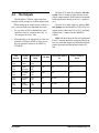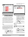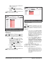
1
026-1705 Rev 7 06-APR-2010 MultiFlex Condensing Unit Board (CUB-II and CUB-TD) Installation and Operation Manual 3240 Town Point Drive NW Suite 100 Kennesaw, GA 30144, USA Phone: 770-425-2724 Fax: 770-425-9319 ALL RIGHTS RESERVED The information contained in this manual has been carefully checked and is believed to be accurate. However, Computer Process Controls, Inc. assumes no responsibility for any inaccuracies that may be contained herein. In no event will Computer Process Controls, Inc. be liable for any direct, indirect, special, incidental, or consequential damages resulting from any defect or omission in this manual, even if advised of the possibility of such damages. In the interest of continued product development, Computer Process Controls, Inc. reserves the right to make improvements to this manual, and the products described herein, at any time without notice or obligation. Table of Contents 1 OVERVIEW OF THE MULTIFLEX CUB-II AND CUB-TD .................................................................................. 1 1.1. THE MULTIFLEX CUB-II.............................................................................................................................................. 1 1.2. THE MULTIFLEX CUB-TD ........................................................................................................................................... 1 2 MOUNTING AND POWERING.................................................................................................................................. 2 2.1. SNAP-TRACK INSTALLATION ........................................................................................................................................ 2 2.2. THE PLUG-IN OUTPUT BOARD ..................................................................................................................................... 3 2.3. POWERING THE MULTIFLEX CUB BOARD ................................................................................................................... 3 2.3.1. Choosing Transformer Sizes ................................................................................................................................. 4 2.3.2. MultiFlex CUB Power Wiring............................................................................................................................... 4 2.3.2.1. New-Style MultiFlex CUB Boards (With Isolated Power Supply) .................................................................................... 5 2.3.2.2. Old-Style MultiFlex CUB Boards (No Isolated Power Supply)......................................................................................... 5 2.3.3. Wire Types and Maximum Distances .................................................................................................................... 6 3 THE I/O NETWORK .................................................................................................................................................... 7 3.1. WIRING TYPES .............................................................................................................................................................. 7 3.1.1. Daisy Chains ......................................................................................................................................................... 7 3.1.2. Network ID Numbers............................................................................................................................................. 7 3.1.2.1. Numbering the MultiFlex CUB ................................................................................................................................................................................................... 8 3.1.3. Setting the Baud Rate ............................................................................................................................................ 8 3.1.4. Setting the Terminating Resistance Jumpers ........................................................................................................ 8 4 CUB INPUT AND OUTPUT SETUP........................................................................................................................... 9 4.1. THE INPUTS ................................................................................................................................................................... 9 4.1.1. Connecting Sensors to the MultiFlex CUB ........................................................................................................... 9 4.1.1.1. Wiring ................................................................................................................................................................................. 9 4.1.1.2. Sensor Wiring Types .......................................................................................................................................................... 9 4.1.1.3. Input Type Dip Switches .................................................................................................................................................... 9 4.1.2. Power Connection ............................................................................................................................................... 10 4.1.2.1. Current Ratings for On-Board Power Sources.................................................................................................................. 10 4.1.2.2. Powering Sensors Requiring 24VAC Off the Power Transformer................................................................................... 10 4.1.3. MultiFlex CUB Fixed Input Locations................................................................................................................ 10 4.2. THE OUTPUTS ............................................................................................................................................................. 11 4.2.1. Relay Output Ratings and Fuse Protection......................................................................................................... 12 4.2.2. Wiring Outputs to Points..................................................................................................................................... 12 4.2.3. MultiFlex CUB Fixed Outputs ............................................................................................................................ 12 5 BOARD STATUS LEDS ............................................................................................................................................. 13 5.1. 5.2. 5.3. 5.4. STATUS LED............................................................................................................................................................... 13 TX AND RX LEDS ....................................................................................................................................................... 13 CODE A AND CODE B LEDS ...................................................................................................................................... 13 RELAY OUTPUT LEDS ................................................................................................................................................ 14 6 MULTIFLEX CUB-II AND CUB-TD SOFTWARE OVERVIEW ........................................................................ 15 6.1. COMPRESSOR CONTROL.............................................................................................................................................. 15 6.1.1. Suction Pressure Compressor Control................................................................................................................ 15 6.1.2. Case Temperature Compressor Control ............................................................................................................. 15 6.1.2.1. Pump Down ...................................................................................................................................................................... 15 6.1.2.2. Fallback Pressure Setpoints .............................................................................................................................................. 15 vi • Table of Contents 026-1705 Rev 7 06-APR-2010 6.2. CONDENSER FAN CONTROL ....................................................................................................................................... 16 6.2.1. Temperature Differential (TD) Strategy ............................................................................................................. 16 6.2.1.1. TD Control Fail-Safes....................................................................................................................................................... 16 6.2.2. Pressure Control Strategy................................................................................................................................... 6.2.3. Case Temperature Control.................................................................................................................................. 6.3. DEFROST CONTROL .................................................................................................................................................... 6.3.1. Defrost Termination............................................................................................................................................ 6.4. SENSOR CONTROL ...................................................................................................................................................... 6.4.1. How Cut In/Cut Out Control Works ................................................................................................................... 6.4.2. Motor Room Temperature Control ..................................................................................................................... 16 17 17 17 17 17 18 6.4.2.1. Exhaust Fan Control ......................................................................................................................................................... 18 6.4.2.2. Example of a Motor Room Zone Temperature Configuration ......................................................................................... 18 6.5. ALARM CONDITIONS (SAFETY MODES) ..................................................................................................................... 6.5.1. High Discharge Trip Safety Mode ...................................................................................................................... 6.5.2. Compressor Proof Fail Safety Mode .................................................................................................................. 6.5.3. Compressor Oil Failure Safety Mode ................................................................................................................. 6.5.4. Phase Fail Mode ................................................................................................................................................. 6.6. DOOR SWITCHES AND CLEAN (WASH) SWITCHES ..................................................................................................... 6.6.1. Door Switches ..................................................................................................................................................... 6.6.2. Clean (Wash) Switches........................................................................................................................................ 19 19 19 20 20 20 20 21 7 THE MULTIFLEX CUB E2/ EINSTEIN INTERFACE ......................................................................................... 22 7.1. ADDING/DELETING A CUB ........................................................................................................................................ 7.1.1. Adding a CUB ..................................................................................................................................................... 7.1.2. Deleting a CUB................................................................................................................................................... 7.2. VIEWING THE CUB STATUS SCREEN ......................................................................................................................... 7.2.1. Inputs and Setpoints ............................................................................................................................................ 7.2.2. Sensor Control .................................................................................................................................................... 7.2.3. Outputs and Operational States.......................................................................................................................... 7.2.4. Defrost................................................................................................................................................................. 7.2.5. KW Usage ........................................................................................................................................................... 7.3. PROGRAMMING THE CUB USING THE E2 OR EINSTEIN FRONT PANEL ..................................................................... 7.3.1. Screen 1: General ............................................................................................................................................... 7.3.2. Screen 2: Setpoints.............................................................................................................................................. 22 22 23 23 24 25 25 26 26 26 27 28 7.3.2.1. Temperature Differential (TD) ......................................................................................................................................... 30 7.3.2.2. Traditional Strategy .......................................................................................................................................................... 30 7.3.3. Screen 3: Inputs .................................................................................................................................................. 7.3.4. Screen 4: Aux Inputs ........................................................................................................................................... 7.3.5. Screen 5: CUB Inputs ......................................................................................................................................... 7.3.6. Screen 6: Defrost ................................................................................................................................................ 7.3.7. Screen 7: Outputs................................................................................................................................................ 7.3.8. Screen 8: CUB Outputs....................................................................................................................................... 7.3.9. Screen 9: Sensor Control .................................................................................................................................... 7.3.10. Screen 10: Alarms............................................................................................................................................. 31 32 32 34 35 37 38 39 7.3.10.1. Oil Failure Alarm Setpoints ............................................................................................................................................ 7.3.10.2. Discharge Pressure Alarm .............................................................................................................................................. 7.3.10.3. High/Low Suction Pressure Alarms ............................................................................................................................... 7.3.10.4. Compressor Proof Alarms .............................................................................................................................................. 7.3.10.5. Phase Fail Shutdown....................................................................................................................................................... 7.3.10.6. Door Switch Alarms ....................................................................................................................................................... 7.3.10.7. Wash Active Alarms ....................................................................................................................................................... 7.3.10.8. Case Temperature Alarms .............................................................................................................................................. 7.3.10.9. Suction Temperature Alarms .......................................................................................................................................... 7.3.10.10. TD Condenser Control Alarms ..................................................................................................................................... 39 40 41 41 42 42 42 42 43 43 MultiFlex CUB-II and CUB-TD I&O Guide Table of Contents • vii 8 THE MULTIFLEX CUB HAND-HELD INTERFACE........................................................................................... 44 8.1. CUB HAND-HELD TERMINAL STATUS SCREENS ....................................................................................................... 44 8.1.1. Pressure Status.................................................................................................................................................... 44 8.1.2. Case Temp Status ................................................................................................................................................ 44 8.1.3. Other Temperatures ............................................................................................................................................ 44 8.1.4. Input Summary Screen ........................................................................................................................................ 45 8.1.5. Outputs Summary Screen #1 ............................................................................................................................... 45 8.1.6. Outputs Summary Screen #2 ............................................................................................................................... 45 8.1.7. System Status ....................................................................................................................................................... 45 8.1.8. Refrigeration Control Status ............................................................................................................................... 45 8.2. ALTERING CUB CONFIGURATION USING THE HAND-HELD TERMINAL .................................................................... 45 8.2.1. The Main Configuration Menu............................................................................................................................ 45 8.2.2. Navigation ........................................................................................................................................................... 46 8.2.3. General Hand-Held Terminal Screens................................................................................................................ 46 8.2.3.1. 8.2.3.2. 8.2.3.3. 8.2.3.4. 8.2.3.5. 8.2.3.6. Circuit Name..................................................................................................................................................................... Refrigerant Select.............................................................................................................................................................. Phase ................................................................................................................................................................................. Temp EU........................................................................................................................................................................... Time and Date................................................................................................................................................................... Daylight Savings Time ..................................................................................................................................................... 46 47 47 47 48 48 8.2.4. Setpoints Screens................................................................................................................................................. 48 8.2.4.1. 8.2.4.2. 8.2.4.3. 8.2.4.4. 8.2.4.5. 8.2.4.6. 8.2.4.7. 8.2.4.8. Condenser Setpoints ......................................................................................................................................................... TD Strat Info ..................................................................................................................................................................... TD Max............................................................................................................................................................................. Comb Method ................................................................................................................................................................... Min OFF/ON Times.......................................................................................................................................................... Condenser SPs .................................................................................................................................................................. Condenser Fan 1 Setpoints ............................................................................................................................................... Condenser Fan 2 Setpoints ............................................................................................................................................... 49 49 49 49 50 51 51 51 8.2.5. Alarm Setpoints Screens...................................................................................................................................... 52 8.2.5.1. Case Hi and Lo Temp ....................................................................................................................................................... 8.2.5.2. Phase Fail .......................................................................................................................................................................... 8.2.5.3. Shut Down On Proof......................................................................................................................................................... 8.2.5.4. Proof Failure ..................................................................................................................................................................... 8.2.5.5. Oil Restart Delay .............................................................................................................................................................. 8.2.5.6. Digital Oil Failure ............................................................................................................................................................. 8.2.5.7. High Discharge Alarm ...................................................................................................................................................... 8.2.5.8. High Discharge Auto Resets............................................................................................................................................. 8.2.5.9. Door Switch ...................................................................................................................................................................... 8.2.5.10. Wash Switch ................................................................................................................................................................... 52 52 52 53 53 53 54 54 54 54 8.2.6. Defrost Setup Screens.......................................................................................................................................... 55 8.2.6.1. 8.2.6.2. 8.2.6.3. 8.2.6.4. Defrost Type ..................................................................................................................................................................... Fan Control ....................................................................................................................................................................... Defrost Times ................................................................................................................................................................... Defrost Schedule Screens 1 and 2..................................................................................................................................... 55 55 56 56 8.2.7. Input Setup Screens ............................................................................................................................................. 56 8.2.7.1. Input Setup ....................................................................................................................................................................... 56 8.2.8. Outputs Screens................................................................................................................................................... 58 8.2.9. Auxiliary Inputs Screens...................................................................................................................................... 58 8.2.9.1. Pulse KW Setup ............................................................................................................................................................... 58 8.2.9.2. Analog KW Setup ............................................................................................................................................................ 58 8.2.9.3. Linear 1 and 2 Setup ......................................................................................................................................................... 58 8.2.10. Sensor Control Screens ..................................................................................................................................... 59 8.2.10.1. Sensor Screen 1 (Name, Type) ...................................................................................................................................... 59 8.2.10.2. Sensor Screen 2 (Cut In/Out, Min ON/OFF) .................................................................................................................. 59 8.2.10.3. Sensor Screen 3 (Hi/Lo Alarm) ...................................................................................................................................... 60 viii • Table of Contents 026-1705 Rev 7 06-APR-2010 8.2.10.4. Sensor Control Screen 4 (Alarm Priority, Comb Method) ............................................................................................. 60 APPENDIX A: TD QUICK START ............................................................................................................................... 62 APPENDIX B: CASE TYPE DEFAULTS ..................................................................................................................... 68 MultiFlex CUB-II and CUB-TD I&O Guide Table of Contents • ix 1 Overview of the MultiFlex CUB-II and CUB-TD The MultiFlex CUB-II and CUB-TD boards are “smart” input/output boards designed to control single condensing units. A single condensing unit is a self-contained compressor and condenser bearing unit which controls refrigeration in a single case line-up or walk-in cooler. The MultiFlex CUB-II controllers are capable of commanding compressors, condensers, refrigeration, and defrost for a single condensing unit using on-board I/O and control algorithms. The CUB-TD controller is a more limited board that controls only condensers, using a temperature differential control strategy. 1.1. The MultiFlex CUB-II The MultiFlex CUB-II controllers are capable of handling all aspects of single condensing unit control, including compressors, condensers, refrigeration, and defrost, using on-board I/O and control algorithms. The CUB-II is capable of controlling one single-stage compressor, refrigeration and scheduled/terminated defrost in a case circuit with up to six temperature inputs, and condenser control using either a control by pressure strategy (activates up to two fans to maintain a set discharge pressure) or temperature differential strategy (activates up to four fans to maintain a set difference between the ambient temperature and the drop leg refrigerant temperature). The MultiFlex’s I/O Points The compact size of the MultiFlex allows technicians to easily field-mount the MultiFlex CUB-II and CUB-TD in a panel or enclosure close to the single condensing unit, allowing for easy local connection of sensors and transducers. The board has 16 analog inputs (for connection to vital input sources, such as suction pressure transducers and case temperature sensors) and eight relay outputs, rated 2.0 amps max, for activating and deactivating compressors, defrost, and condenser fans. Independent System Control The MultiFlex CUB-II and CUB-TD controllers are equipped with software and an enhanced processor, which gives them the capability of controlling independently without the need of a central controller (such as CPC’s E2 or Einstein RX Refrigeration Controller). However, the CUB-II and CUB-TD are designed to interface with an E2 or Einstein for purposes of displaying status on status screens, reporting alarms, and recording logs. The CUB-II and CUB-TD may be configured either with a CPC Hand-Held Terminal (HHT) or through the E2 or Einstein front panel. The MultiFlex CUB-II 1.2. The MultiFlex CUB-TD The MultiFlex CUB-TD is a “stripped” version of the MultiFlex CUB-II that includes only an algorithm for temperature differential (TD) condenser fan control. Up to four condensing unit fans are cycled on and off as required to meet compressor unit heat of rejection load. The TD algorithm subtracts plenum air temperature from the drop leg temperature and uses the difference between the two temperatures as a control value. If the difference is higher than the setpoint, the fans are staged on. If the difference is lower than the setpoint, the fans are staged off. The temperature differential control capabilities of the CUB-TD are identical to those of a CUB-II operating in temperature differential mode, except the CUB-TD controls condensers only. The CUB-TD only has inputs for reading temperatures and outputs for controlling up to four fans. For control of any other single condensing unit subsystem, a CUB-II will necessary. Overview of the MultiFlex CUB-II and CUB-TD • 1 2 Mounting and Powering The MultiFlex boards are usually mounted by the refrigeration equipment manufacturer. Therefore, the installer need only make the necessary connections between the boards and the site controller(s). 2.1. Snap-Track Installation MultiFlex boards not supplied in a custom panel or other enclosure are supplied with a snap-track for easy installation. The insulation sheet and I/O board must be removed from the track before the track is mounted. The snap-track is mounted using the 0.1875” mounting slots. Figure 2-1 shows this installation procedure. In some instances, an installer may be required to mount an I/O board. There are no restrictions on the location of these boards; however, for ease of network configuration, it is recommended that the boards be located adjacent to the E2 or Einstein. I/O boards may be mounted without an enclosure, but they should be mounted in a location that is not easily accessible to avoid tampering or damage. Figure 2-1 - MultiFlex Snap-Track Mounting Figure 2-2 provides mounting dimensions for the MultiFlex board. Figure 2-2 - MultiFlex Board Dimensions 2 • MultiFlex CUB-II and CUB-TD I&O Guide 026-1705 Rev 7 06-APR-2010 2.2. The Plug-In Output Board The additional board makes the MultiFlex CUB boards considerably taller than the MultiFlex 16 and other CPC I/O boards. If you will be mounting these boards in an enclosure, the board will need at least 2.5” of clearance between the baseboard and the panel door. 2.3. Powering the MultiFlex CUB Board WARNING: All models of MultiFlex require a 24VAC Class 2 input power source. The MultiFlex CUB-II requires the power source to be non-center-tapped. Refer to Section 2.3.1., Choosing Transformer Sizes for center tap usage. CPC supplies a wide variety of 24VAC transformers with varying sizes and either with or without center taps. Table 2-1 shows the transformer sizes and whether they are center-tapped or non-center-tapped. Figure 2-3 - Exploded View — MultiFlex CUB-II The MultiFlex CUB has an output sub-board that plugs to the top of the baseboard. Typically, these boards are shipped with the output board pre-installed on the board using stand-offs, so no additional hardware setup should be necessary. Xformer P/N VA Rating Primary Voltage Center Tap? 640-0041 50 VA 110 VAC No 640-0042 50 VA 220 VAC No 640-0056 56 VA Multi-tap (120/208/240 VAC) Yes 640-0050 75 VA 110 VAC No 640-0045 75 VA 220 VAC No 640-0080 80 VA Multi-tap (120/208/240 VAC) Yes Table 2-1 - Transformers Compatible with Datalink Module The Plug-In Output Board Mounting and Powering • 3 2.3.1. Choosing Transformer Sizes In most site installations, a single transformer will power multiple devices. Choose a transformer with a VA rating large enough to power all devices that will be attached to it. Table 2-2 gives the VA ratings of the MultiFlex CUB in conjunction with other MultiFlex boards. Refer to your site controller’s manual for VA ratings of the other I/O boards that may be powered by one of these transformers. Unit VA VAC CenterTapped? MultiFlex 16 6 24 Yes MultiFlex 88, 88AO, 168, and 168AO 15 24 NO MultiFlex RTU 15 24 NO MultiFlex CUB 15 24 NO A new-style MultiFlex board has a green power LED located next to the 24VAC connection terminal in the upper right corner of the circuit board (see Figure 2-4 for reference). 24 VAC POWER LED New Style MultiFlex Board (Top Left Corner) 24 VAC NO POWER LED Table 2-2 - Device Power Requirements 2.3.2. MultiFlex CUB Power Wiring The MultiFlex CUB boards do not use a center tap. Instead, the 0V terminal on the board should be connected to a separate earth ground. Important! The rules that must be followed when connecting a MultiFlex CUB board to a transformer are different depending on whether you have a "new style" MultiFlex board with an isolated power supply (all MultiFlex boards shipped after November 1, 2002) or an "old style" MultiFlex board (all MultiFlex boards shipped before November 1, 2002). 4 • MultiFlex CUB-II and CUB-TD I&O Guide Old Style MultiFlex Board (Top Left Corner) Figure 2-4 - New-Style vs. Old-Style MultiFlex Board If there is a green power LED next to the connector, your MultiFlex is a new-style MultiFlex -- refer to Section 2.3.2.1., New-Style MultiFlex CUB Boards (With Isolated Power Supply) for power wiring instructions. If there is no green power LED next to the connector, your MultiFlex is an old-style MultiFlex -- refer to Section 2.3.2.2., Old-Style MultiFlex CUB Boards (No Isolated Power Supply) for power wiring instructions. 026-1705 Rev 7 06-APR-2010 2.3.2.1. New-Style MultiFlex CUB Boards (With Isolated Power Supply) The new-style MultiFlex board can be connected to any of the center-tapped transformers mentioned in Table 2-2, provided the 0V terminal of the board is connected to an earth ground. In addition, the MultiFlex CUB boards can be powered by one of the 50VA or 75VA noncenter-tapped transformers listed in Table 2-1 on page 3. Figure 2-6 shows how to wire the transformers to the MultiFlex boards. NOTE: 14AWG or larger should be used for earth ground and the length should be kept short. Less than six inches is preferred. A center-tapped transformer may power both center-tapped and non-center-tapped devices at the same time, as long as none of the non-center-tapped MultiFlex boards are oldstyle MultiFlex boards. If an old-style MultiFlex shares the same center-tapped transformer as a device that uses the center tap, the old-style MultiFlex will be damaged. Figure 2-5 shows how to wire a non-center-tapped device to a center-tapped transformer. Earth ground. Use 14 AWG or larger. Keep as short as possible. Less than six inches is preferred. Figure 2-5 - Wiring Non-Center-Tapped MultiFlex Boards to Transformers With a Center Tap Figure 2-6 - Non-Center-Tapped Transformer Wiring 2.3.2.2. Old-Style MultiFlex CUB Boards (No Isolated Power Supply) Like the new-style MultiFlex board, the oldstyle MultiFlex board can be connected to any of the center-tapped transformers mentioned in Table 2-2, provided you observe the following three rules: Rule 1: Ground the 0V terminal on the oldstyle MultiFlex board to an earth ground. Do not connect the center tap of the transformer to the 0V terminal. Rule 2: Do not power an old-style MultiFlex non-center-tapped board with a transformer that is also powering a center-tapped device. This means you cannot connect an old-style MultiFlex non-center-tapped board to a transformer that is powering a MultiFlex 16, 16AI, 8RO, 4AO, 8DO, or any previous generation CPC board that uses center-tapped power. Doing so will destroy the MultiFlex board. Rule 3: The secondary of the transformer must not be grounded on any side. Powering the MultiFlex CUB Board Mounting and Powering • 5 Verify that neither side of the transformer secondary is connected to earth ground before powering the old-style MultiFlex board. A grounded secondary will damage the MultiFlex board. Use these formulas to determine if the wire gauge you are using fits within specification: 14 AWG: Feet = 1920/VA In addition, the old-style MultiFlex CUB boards can be powered by one of the 50VA or 75VA non-center-tapped transformers listed in Table 2-1 on page 3. Figure 2-6 shows how to wire the transformers to the MultiFlex boards. 18 AWG: 2.3.3. Wire Types and Maximum Distances 18 AWG: 9 ft (rounded down) Figure 2-7 - Power Wire Lengths For powering I/O boards, use only the listed wire types from Table 2-3. Three-conductor nonshielded cables are the recommended wire for connecting between the center-tapped transformer and the I/O boards. Shielded cable should not be used for power wiring. The center tap should be wired with the third conductor to earth ground at the controller. (Use 14AWG and keep the length of wire short. Less than six inches is preferred). Sensors requiring 24VAC can be powered from the same transformer powering the input board as long as the resulting total load of both the input board(s) and the sensor(s) connected to the transformer does not exceed the transformer’s VA rating, and the sensors have an isolated power supply. If the sensors do not have an isolated power supply, they could be damaged if connected with center-tapped or grounded secondary transformers. Feet = 739/VA (VA is the total VA rating of the I/O boards) For example, if you had an 80 VA load: 14 AWG: 24 ft Power Wiring Types 14 AWG Belden 9495 18 AWG Belden 9493 Table 2-3 - Power Wiring Types The wire length from the transformer and the number of boards connected to the same wire determines the type wire gauge used. In most cases, the distance between the I/O boards and the transformer that supplies power to them is not enough to be concerned with. But it is very important not exceed this maximum wire length or the boards will malfunction. 6 • MultiFlex CUB-II and CUB-TD I&O Guide 026-1705 Rev 7 06-APR-2010 3 The I/O Network Although the MultiFlex CUB can operate as a stand-alone controller, it relies on an E2, Einstein, or REFLECS unit for advanced features such as remote dial-in/dial-out, logging, and alarm control. All MultiFlex boards and controllers use an RS485 Network connection to communicate with an E2, Einstein, and REFLECS site controllers. Technicians who are familiar with CPC’s previous generation 16AI, 8IO, and ARTC boards will find the network setup procedure for the MultiFlex CUB boards to be very much the same. 3.1. Wiring Types put communication boards, and terminates at the last input or output board on the network. A diagram of this network arrangement is shown in Figure 3-1. Figure 3-1 - I/O Network Configurations 3.1.2. Network ID Numbers CPC specs Belden #8761 shielded twisted pair cables for use as I/O Network wiring (or Belden #82761 and Belden #88761 for plenum installations). Each device on an RS485 segment has a network dip switch that must be used to assign the board a unique network ID number. If the recommended cable is not available in your area, be sure the wiring meets or exceeds the following specs: The network ID number makes a board unique from other boards on the network of the same type. This allows the site controller to find it and communicate with it easily. Shielded? Yes Conductor Type Twisted Pair Gauge 18 - 24 AWG Capacitance between signal wires 31 pF/ft or less Capacitance between signal and shield 59 pF/ft or less Nominal Impedance Boards of the same type should be numbered in sequence, starting with one and continuing with two, three, and so forth. 12050 Table 3-1 - RS485 I/O Network Wiring Specifications 3.1.1. Daisy Chains The RS485 Input/Output (I/O) Network connects all input and output communication boards together in a single open communications loop. This loop, or “daisy chain,” connects the E2, Einstein, or REFLECS to multiple input and out- Wiring Types The I/O Network • 7 3.1.2.1. Numbering the MultiFlex CUB The MultiFlex CUB is a unique board type on the RS485 Network by the CPC controllers. Each CUB that will be associated with an E2 or Einstein must have a unique number from 1 to 31, which is configured by setting the first five switches on dip switch bank S3. 3.1.4. Setting the Terminating Resistance Jumpers All MultiFlex boards and other RS485 devices have a set of terminating resistance jumpers (one jumper for each wire lead). These jumpers are labeled JP2, JP3, and JP4 on the MultiFlex board. The purpose of the jumpers is to indicate the two ends, or termination points, of the segment. On a daisy chain, one device at the beginning and one device on the end must be terminated by placing all three termination jumpers in the OUT (toward the left edge of the board) position. All other devices on the daisy chain must be set to the IN (toward the center of the board) position. Figure 3-3 shows the proper terminating resistance jumper settings for the E2, Einstein, and for all I/O boards. Figure 3-2 - CUB-II Baud Rate Switches 3.1.3. Setting the Baud Rate All I/O boards have dip switches that determine the baud rate at which they communicate. Currently, the baud rate dip switch in network components may be set at either 9600 or 19200 baud. Either may be used — refer to your site controller’s user manual for the baud rate recommendation (currently 9600 baud for REFLECS, E2, and Einstein controllers). Figure 3-3 - I/O Network Termination Jumper Settings On all MultiFlex boards, switches 6 and 7 on S3 are used to set the baud rate. To communicate at 9600 baud, set switch #6 UP and #7 DOWN. For 19200 baud, set switch #6 DOWN and #7 UP. Refer to Figure 3-2 for a visual look at how the switches must be set. 8 • MultiFlex CUB-II and CUB-TD I&O Guide 026-1705 Rev 7 06-APR-2010 4 CUB Input and Output Setup 4.1. The Inputs All Pressure Transducers, Humidity Sensors, and Refrigeration Transducers Pressure and refrigeration transducers and humidity sensors are to be wired with shielded, 3 conductor, at least 22 GA wire (Belden #8771 or equivalent). Dewpoint and Light Level Sensors 4.1.1. Connecting Sensors to the MultiFlex CUB These sensors are to be wired with shielded, 4 conductor at least 22 GA wire (Belden # 8729 or equivalent). Wiring an input to the input points on a MultiFlex board requires three steps: 4.1.1.3. 1. Connect the sensor’s signal wires to the two terminals of an input point. Each MultiFlex input point has an input type dip switch that must be set. Input type dip switches are located in the switch banks labeled S1 and S2. 2. Set the input type dip switch that corresponds to the point being connected. 3. If necessary, connect the sensor to one of the 5V or 12V power terminals. 4.1.1.1. Wiring An input point on a MultiFlex board consists of two terminals, as shown in Figure 4-1. One of these terminals, labeled SIG, reads the signal from the sensor, while the other, labeled 0v is where the sensor’s ground and/or cable shield wire is connected. Input Type Dip Switches The input type dip switch tells the input board whether or not the sensor connected to the point is a resistive type sensor. Generally, if the sensor or transducer supplies its own voltage signal to the point, the dip switch should be set to the LEFT position. If the sensor uses variable resistance and requires voltage to be supplied to it from the input point, set the dip switch to the RIGHT position. Dip switches for unused points should be set to the RIGHT position. Figure 4-2 - Input Type Dip Switches for CUB Board Figure 4-1 - Input Board Points 4.1.1.2. Sensor Wiring Types Specific wiring types are required for each type of sensor used with E2, Einstein, or RMCC. All Analog Temperature Sensors and Air Flow Sensors Temperature and air flow sensors are to be wired with shielded, 2 conductor, at least 22 GA wire (Belden # 8761 or equivalent). The Inputs CUB Input and Output Setup • 9 4.1.2. Power Connection If power is needed to operate the sensor, four points are provided on the MultiFlex board that supply DC power: one +12VDC point, and three +5VDC points. See Figure 4-3 for the location of these points. Figure 4-3 - Input Board Power Sources To connect to one of the DC power sources, simply connect the sensor’s power wire to one of the terminals. A sensor that requires 24VAC can be powered off the MultiFlex’s own 24VAC power connection. To connect to the 24VAC power source, connect the sensor’s power wires to terminals AC1 and AC2. 4.1.2.1. Current Ratings for On-Board Power Sources This can only be done with sensors that keep the 24VAC signal isolated from its DC output signal (such as CPC’s Dewpoint Probe). If the output signal is not isolated from the 24VAC input, you must use a separate transformer. 4.1.3. MultiFlex CUB Fixed Input Locations The MultiFlex CUB supports a large number of different types of input sources that might be found on a single condensing unit’s pressure control, condenser control, or refrigeration control systems. Because input locations are specified by the user in the system software, you can connect inputs from the condensing unit to any point on the CUB. However, to make setup easier, the CUB has assigned default sensor locations to a few of the inputs on the board. Table 4-1 lists the inputs with assigned defaults. If you choose to not use the defaults listed, you may change any or all of them in the system software (see Section 7.3.3., Screen 3: Inputs and Section 8.2.7., Input Setup Screens). CUB Input Point Number Sensor to Connect To This Point Label 1 The maximum current that may be drawn from the +12VDC terminal is 100 milliamps. The maximum current that can be drawn from all three +5VDC terminals COMBINED is 50 milliamps. Suction Transducer 0-100PSI Pressure Transducer, measuring suction pressure 2 Discharge Transducer 0-500PSI Pressure Transducer, measuring discharge pressure 4.1.2.2. 3 Oil Transducer 0-200PSI Pressure Transducer, for measuring oil pressure 4 Case 1 Temp Discharge air temperature sensor for the cooler or case lineup 16 Alarm Reset Digital contact closure (switch or push button) to reset alarms Powering Sensors Requiring 24VAC Off the Power Transformer Some sensors that requires 24VAC can be powered off the MultiFlex’s own 24VAC power connection. To connect to the 24VAC power source, connect the sensor’s power wires to terminals AC1 and AC2. Table 4-1 - CUB Default Inputs 10 • MultiFlex CUB-II and CUB-TD I&O Guide 026-1705 Rev 7 06-APR-2010 4.2. The Outputs The MultiFlex CUB has eight relays that energize and de-energize to control output loads. When setting up an output on one of these relays, you must make two important decisions: 1. Do you want an ON command from your controller to mean “energize the relay” or “de-energize the relay,” and 2. When the relay is de-energized, as is the case when the CUB goes offline or loses power, do you want the contacts to be OPEN or CLOSED? HHT Display Contact State Equipment State Fail Safe Decision #1 is made by setting the fail-safe switch. This is a bank of eight switches on the plug-in output module. Each switch corresponds to an output on the board (switch #1 = output #1, etc.). Decision #2 is made either by setting a failsafe jumper (for the MultiFlex CUB) or by wiring the load to either the N.O. or N.C. terminals on the Form C contact (for the MultiFlex 16I8O). Table 4-2 shows how the fail-safe switch and Form C contacts should be configured based on how you want the output to perform during both normal operation and during network/power loss. Set Failsafe Switch To: Form C Contacts Used: ON OFF CLOSED OPEN ON OFF ON UP N.C ON OFF OPEN CLOSED OFF ON OFF UP N.O ON OFF CLOSED OPEN OFF ON OFF UP N.C. ON OFF CLOSED OPEN OFF ON ON DOWN N.O ON OFF OPEN CLOSED ON OFF OFF DOWN N.C ON OFF CLOSED OPEN ON OFF OFF DOWN N.O Table 4-2 - Output Board Fail-Safe and Switch Settings The Outputs CUB Input and Output Setup • 11 4.2.1. Relay Output Ratings and Fuse Protection Each relay output on the MultiFlex Combination I/O boards is rated for up to 240 VAC with a maximum current of 2 amps. Table 4-1 lists the inputs with assigned defaults. If you choose to not use the defaults listed, you may change any or all of them in the system software (see Section 7.3.7., Screen 7: Outputs and Section 8.2.8., Outputs Screens). Each relay is fused with a 2 amp fast-blow 5mm x 20mm fuse, Bussman GMA-2 or equivalent. 4.2.2. Wiring Outputs to Points The MultiFlex CUB has Form C relay contacts. Figure 4-4 shows how to wire the threeterminal Form C contact. One wire of the two-wire connection should always be connected to the middle terminal. The second wire must either be connected to the N.C. terminal (if you want the path to be closed when the relay is de-energized) or the N.O. terminal (if you want the path to be open during power failure). RELAY IS CLOSED ON POWER FAILURE N.C. N.O. RELAY IS OPEN ON POWER FAILURE CUB Output Point Number Device to Connect To This Point Label 1 Compressor Compressor 2 Defrost Electric defrost heaters or hot gas valve 3 Condenser Fan #1 Condenser fan (or 1st condenser fan if multiple fans are present) 8 Alarm Output Digital contact closure that is ON when an alarm condition is active in the condensing unit. Table 4-3 - CUB Default Outputs N.C. N.O. Figure 4-4 - Form C Contact Wiring 4.2.3. MultiFlex CUB Fixed Outputs The MultiFlex CUB supports a large number of different types of output devices that might be found on a single condensing unit’s pressure control, condenser control, or refrigeration control systems. Because output locations are specified by the user in the system software, you can connect outputs from the condensing unit to any point on the CUB. However, to make setup easier, the CUB has assigned default sensor locations to a few of the inputs on the board. 12 • MultiFlex CUB-II and CUB-TD I&O Guide 026-1705 Rev 7 06-APR-2010 5 Board Status LEDs When a MultiFlex board is powered up, you will be able to determine the operating status of the board by observing its status LEDs. Figure 5-1 shows the location of the MultiFlex’s status LEDs. Figure 5-1 - MultiFlex Status LED Locations 5.1. Status LED The Status LED blinks green once per second to show that the board is powered and operational. If this light is dark, the board has likely lost power. 5.2. Tx and Rx LEDs The Tx and Rx LEDs indicate when the MultiFlex is sending or receiving messages on the RS485 Network. The Tx LED blinks once every time the MultiFlex sends a response to the E2, Einstein, or REFLECS. The Rx LED blinks once when the MultiFlex receives a message. If the MultiFlex is connected to the network and set up to communicate with the controller, you should see these lights blinking regularly. If they do not, there may be a problem with the network. 5.3. Code A and Code B LEDs All MultiFlex models except the MultiFlex 16 have two LEDs labeled Code A and Code B. These LEDs indicate failure conditions. When these LEDs are OFF, there are no failures active. When one or both of these LEDs are blinking, there are failure conditions. The rate of blinking indicates the type of failure: Code A Failure Conditions • Blinking fast (4 times/second) - There is a problem with the flash memory or hardware clock on this board. This generally means the board is bad and must be replaced. • Blinking slow (1 time/second) - The board is not receiving any messages addressed to it. This means ei- Status LED Board Status LEDs • 13 ther the I/O Network is down or it has not yet been commissioned in the E2, Einstein, or REFLECS Network Configuration screen. Code B Failure Conditions • Blinking 2 times/second - The battery on this board that backs up the CUB configuration during power failures has failed. If you see this light flashing, the battery will need to be replaced to avoid loss of configuration. Also, check the position of the Enable Battery jumper, located at the bottom right of the board just underneath the output plug-in board. If this jumper is set to the DOWN position, move it to the UP position. This will enable the battery and should cause the Code B light to stop flashing. 5.4. Relay Output LEDs Each relay output point on a MultiFlex has an indicator LED that shows the status of the output. This LED is lit to show the output is ON, and unlit to show the output is OFF. The definition of ON and OFF in this case is determined by the position of the fail-safe dip switch (see Table 4-2). Therefore, if the output’s switch is UP, a lit LED means the path is CLOSED for N.C. contacts and OPEN for N.O. contacts. 14 • MultiFlex CUB-II and CUB-TD I&O Guide 026-1705 Rev 7 06-APR-2010 6 MultiFlex CUB-II and CUB-TD Software Overview The CUB-II is capable of controlling all vital systems of a single condensing unit, including compressors, condenser fans, evaporators and case circuit systems. Extended logging and alarm control capabilities require connection to an E2 or Einstein RX refrigeration controller. 6.1. Compressor Control Since a single condensing unit has a single compressor, the MultiFlex CUB-II’s pressure control strategy uses simple Cut In/Cut Out strategy for activating and deactivating the compressor. The compressor may be controlled either by suction pressure or case temperature. 6.1.1. Suction Pressure Compressor Control Using the Suction Pressure Control strategy, the CUB-II compares the suction pressure to a set of Cut In/Cut Out setpoints. If the suction pressure rises higher than the Cut In setpoint, the compressor is activated and remains activated until the suction pressure falls below the Cut Out setpoint. To prevent short-cycling of the compressor, minimum ON and OFF times may be used in this strategy. 6.1.2. Case Temperature Compressor Control Using the Case Temperature Control strategy, the CUB-II only activates the compressor when refrigeration is necessary in the case. This strategy uses a temperature setpoint and a deadband. When the case temperature is above the Compressor Control setpoint plus one-half the deadband, the compressor will turn ON and will remain ON until the case temperature falls below the setpoint minus one-half the deadband. NOTE: A suction transducer is required even for temperature control and is used to prevent the compressor from operating below the minimum suction pressure setpoint. 6.1.2.1. Pump Down If the CUB-II is using the Temperature strategy, it also has the option of using a special Pump Down mode to pump refrigerant out of the evaporator coil when going from Refrigeration to Idle or from Refrigeration to Defrost. A Pump Down causes the refrigeration solenoid to shut while keeping the compressor ON. The compressor will remain ON until the suction pressure drops below a minimum setpoint (or until a fail-safe time elapses). Idle Pump Down With Door Switches If a door switch is available and Idle Pump Down mode is enabled, the CUB-II will do a Pump Down every time a door switch is activated. 6.1.2.2. Fallback Pressure Setpoints When in Temperature strategy, if the case temperature sensors fail or the CUB-II is otherwise unable to determine the case circuit air temperature, the CUB-II will cease operating in Case Temperature Compressor Control mode and use fallback suction pressure Cut In/Cut Out setpoints to control the compressor. This fallback mode operates exactly like the Suction Pressure Compressor Control mode described in Section 6.1.1. The CUB-II will continue to operate using the fallback pressure setpoints until a case temperature sensor value becomes available. The CUB-II will then resume Temperature strategy control. MultiFlex CUB-II and CUB-TD Software Overview • 15 6.2. Condenser Fan Control 6.2.1. Temperature Differential (TD) Strategy Temperature differential strategy attempts to keep a minimum amount of difference between the temperature of the refrigerant and the ambient temperature. The CUB-II and CUB-TD temperature differential strategy uses drop leg temperature for the refrigerant temperature and plenum temperature for the ambient temperature. The formula for determining the TD control value is: TD = (dropleg temp) + (dropleg offset*) plenum temp. * DropLeg Offset is a user-configured parameter to allow fine-tun- Drop Leg Temperature Above Maximum Drop Leg Setpoint If the drop leg temperature (DropLeg Temp) rises above the maximum drop leg temperature setpoint (DropLeg Max), an increase will be called for until DropLeg Temp drops below DropLeg Max. This protects against the possibility of the DropLeg Temp rising too high as a result of high plenum temperature. Drop Leg Temperature Below Minimum Drop Leg Setpoint If the drop leg temperature drops below the minimum drop leg temperature setpoint (DropLeg Min) a decrease will be called for until DropLeg Temp rises above DropLeg Min. This protects against the possibility of the DropLeg Temp falling too low as a result of low plenum temperature. ing of the drop leg temperature measurement. Plenum Temperature Not Available In TD condenser control operation, when the TD rises above TD setpoint + (TD deadband / 2), an increase in fan capacity is called for. Similarly, when the TD drops below TD setpoint (TD deadband / 2), a decrease in fan capacity is called for. TD can control up to four condenser fans. If plenum temperature is not available (due to probe or communication failure), control will be based on the DropLeg Min and Max setpoints. 6.2.1.1. TD Control Fail-Safes TD control operates as explained in Section 6.2.1. as long as plenum and drop leg temperature inputs are available and the drop leg temperature remains within a minimum/maximum range configured by the user. Otherwise, TD control uses various fail-safe modes to maintain proper operation of condenser control. Drop Leg Temperature Not Available In the event drop leg temperature is not available (due to probe failure), all fan stages will be staged on. 6.2.2. Pressure Control Strategy Pressure control strategy uses Cut In/Cut Out setpoints for control based on discharge pressure. The CUB-II can control a maximum of two fans using this strategy. This strategy is not available in the CUB-TD. Traditional strategy condenser fan control simply compares the value of the discharge pressure transducer to a set of Cut In/Cut Out setpoints for each fan. If the discharge pressure rises above the Cut In setpoint for a fan, that fan will turn ON and will remain active until the discharge pressure falls below the fan’s Cut Out setpoints. Condenser fans may be programmed with a minimum ON time to prevent short-cycling. 16 • MultiFlex CUB-II and CUB-TD I&O Guide 026-1705 Rev 7 06-APR-2010 6.2.3. Case Temperature Control Case temperature control supports using a combination of up to six case temperature inputs as the control input. The CUB-II also supports multiple strategies for combining multiple case temp inputs, including minimum temp, maximum temp, and average temp. 6.4.1. How Cut In/Cut Out Control Works Cut In/Cut Out setpoints work differently depending upon whether the Cut In/Cut Out setpoint is higher. Cut In Higher Than Cut Out 6.3. Defrost Control The CUB-II controls scheduled defrosts for its case circuit, and supports both electric and off-cycle (or timed) defrost. Up to 12 daily scheduled defrost times can be programmed in the CUB-II memory. The CUB-II executes defrost cycles at each scheduled time. 6.3.1. Defrost Termination The CUB-II allows for defrost termination based on temperature or suction pressure. Temperature termination can use either a digital defrost sensor (or Klixon) or an analog termination sensor, whose value is compared to the termination setpoint. Suction pressure termination will terminate a defrost cycle when the suction pressure rises above a programmed suction pressure termination setpoint. Figure 6-1 - Cut In Setpoint Higher than Cut Out When the Cut In setpoint is higher than the Cut Out setpoint, the Sensor Control output turns ON when the sensor input goes higher than the Cut In setpoint. The Sensor Control output remains ON until the input falls below the Cut Out setpoint, at which time the output turns OFF. (See Figure 6-1 for an illustration). Defrost cycles may be programmed with a minimum defrost time and a maximum defrost time. 6.4. Sensor Control The CUB-II provides for up to two generic Cut In/Cut Out control algorithms for use in controlling subsystems related to the condensing unit. Each sensor control application consists of an input (or a set of inputs combined into a single value), a set of Cut In/Cut Out setpoints, and a digital output that is controlled by comparing the input to the setpoints. Typical uses for a sensor control application on a CUB-II include: refrigerant leak detection, motor room temperature control, and case lights. Defrost Control MultiFlex CUB-II and CUB-TD Software Overview • 17 Cut In Lower Than Cut Out read this value into Global Data as SPARE ANLG02. All other CUB-IIs that are assigned to zone 2 will read SPARE ANLG02 as the motor room temp. 6.4.2.1. Exhaust Fan Control The CUB-II in each zone that is reading the motor room temp may also use the input to perform Cut In/Cut Out control of a single output. This can drive an exhaust fan or similar HVAC device. 6.4.2.2. Figure 6-2 - Cut In Setpoint Lower Than Cut Out When the Cut In setpoint is lower than the Cut Out setpoint, the Sensor Control output turns ON when the sensor input goes lower than the Cut In setpoint. The Sensor Control output remains ON until the input rises above the Cut Out setpoint, at which time the output turns OFF. (See Figure 6-2 for an illustration). 6.4.2. Motor Room Temperature Control Part of the capabilities of sensor control involves the control of temperature in a motor room. The CUB-II takes a “zone control” approach to controlling motor room temperature. All the CUB-IIs attached to a single E2 or Einstein can be divided into up to four “zones” (physically, up to four different motor rooms). In each zone, one CUB-II must be set up with a sensor control input designated as “Motor Room Temp.” This temperature value is shared with E2 or Einstein’s Global Data handler, and passed back down through Global Data to all CUB-IIs that share the same zone number. Example of a Motor Room Zone Temperature Configuration An example of how motor room temperature zone control is shown in Figure 6-1. In this example, there are two motor rooms with five CUB-IIs each. Each motor room has an exhaust fan that is controlled by the same CUB-II that has the motor room temp probe. This fan is controlled entirely by the individual CUB-II. The motor room temperature for Zones 1 and 2 are passed to E2 or Einstein as the Global Data values SPARE ANLG01 and SPARE ANLG02. All the CUB-IIs in Zone 1 except the one with the sensor will read the SPARE ANLG01 Global Data value as their zone’s motor room temp, and will display this value on their HHT status screens. WARNING: If you are using CUB-IIs, you cannot use Global Data’s SPARE ANLG 01 through 04 inputs for any purpose other than motor room temperature control. If you need to use some of Global Data’s “Spare Analog” slots to share values between E2s or Einsteins, use SPARE ANLG 05 through 08. In an E2 or Einstein that has CUB-II boards attached to it, the Global Data values SPARE ANLG01 through SPARE ANLG04 are reserved for motor room temperatures in zones 1-4. If, for example, a CUB-II in zone 2 has a “Motor Room Temp” sensor control input, E2 or Einstein will 18 • MultiFlex CUB-II and CUB-TD I&O Guide 026-1705 Rev 7 06-APR-2010 Resetting a High Discharge Trip Resetting a high discharge trip safety mode can be done manually by closing the Alarm Reset input on the CUB-II or by resetting the High Discharge Trip alarm in the E2 or Einstein alarm log. You can also program the CUB-II to autoreset when the discharge pressure falls below the discharge trip setpoint minus a user-defined differential. This ensures the pressure will drop well below the trip setpoint before re-starting the compressor. Figure 6-1 - Example of Zone Temperature Control Setup 6.5. Alarm Conditions (Safety Modes) When certain conditions are detected, the CUB-II and CUB-TD operate in a special mode (called Safety mode) in order to correct the condition or to prevent equipment, product, and/or energy loss. Safety mode alarm conditions can be reset two different ways: 1. Resetting the alarm in the E2 or Einstein Alarm Log will reset all active Safety mode alarms. 2. Defining an alarm reset input on the CUB-II, and then manually closing the input will reset all active Safety mode alarms. 6.5.1. High Discharge Trip Safety Mode The CUB-II will always try to prevent the condensing unit’s discharge pressure from rising above a user-defined setpoint, called the discharge trip setpoint. If the discharge pressure ever rises above this setpoint, the CUB will enter the High Discharge Trip Safety mode. This will lock the compressor OFF, and cause the Circuit State of the CUB to display Rack Fail in the E2 or Einstein and HHT status screens. Alarm Conditions (Safety Modes) When using auto-reset, you may also set a maximum number of auto-reset attempts. The CUB will only attempt an auto-reset if it has not already auto-reset the CUB a number of times in the past hour equal to the user-defined maximum. If CUB’s auto-reset maximum has already been met, it will remain in High Discharge Trip mode until it is manually reset. 6.5.2. Compressor Proof Fail Safety Mode If the CUB-II has a Compressor Proof input configured, it can use this input to verify the compressor is operating properly. Under normal conditions, the CUB-II will expect the proof input to mirror the state of the compressor at all times (i.e., proof registers ACTIVE when the compressor is ACTIVE, and INACTIVE when the compressor is INACTIVE). If the proof input does not mirror the value of the compressor state for a period of time longer than a user-defined period, the CUB-II will enter Proof Fail mode. In Proof Fail mode, you may either choose to program the CUB-II to shut down the compressor until the failure is cleared, or to keep attempting to activate/deactivate the compressor as normal. MultiFlex CUB-II and CUB-TD Software Overview • 19 Resetting a Compressor Proof Failure Resetting a Compressor Proof Failure Safety mode can be done manually by closing the Alarm Reset input on the CUB or by resetting the Compressor Proof Fail alarm in the E2 or Einstein alarm log. You can also program the CUB-II to autoreset when the proof input state indicates the compressor is physically behaving as commanded. When using auto-reset, you may also set a maximum number of auto-reset attempts. The CUB-II will only attempt an auto-reset if it has not already auto-reset the CUB-II a number of times in the past hour equal to the userdefined maximum. If CUB-II’s auto-reset maximum has already been met, it will remain in Compressor Proof Fail mode until it is manually reset. 6.5.3. Compressor Oil Failure Safety Mode The CUB-II can monitor compressor oil pressure using either an oil pressure transducer or a digital oil pressure switch. When a low oil pressure condition occurs, CUB-II can be programmed to lock the compressor OFF to prevent equipment damage. Resetting an Oil Failure Resetting an Oil Fail Safety mode can be done manually by closing the Alarm Reset input on the CUB or by resetting the “Oil Failure” alarm in the E2 or Einstein alarm log. You can also program the CUB-II to autoreset when the oil failure input state indicates the oil pressure has returned to normal. When using auto-reset, you may also set a maximum number of auto-reset attempts. The CUB-II will only attempt an auto-reset if it has not already autoreset the CUB-II a number of times in the past hour equal to the user-defined maximum. If CUB-II’s auto-reset maximum has already been met, it will remain in Oil Fail mode until it is manually reset. 20 • MultiFlex CUB-II and CUB-TD I&O Guide 6.5.4. Phase Fail Mode If a phase fail checking device is present onsite, the CUB-II can be programmed to shut down multiple-phase devices it controls. To enable phase protection, a digital phase fail checking device must be connected to one of the CUB-II’s physical inputs. When this input signifies a phase failure has occurred, the CUBII immediately shuts down the compressor, the condenser fans, and the defrost output. CUB-II will lock these devices OFF until the phase failure is over. NOTE: CUB-II will not lock out evaporator fans when a phase fail occurs, because these are single-phase devices. 6.6. Door Switches and Clean (Wash) Switches The MultiFlex CUB-II has special modes of operation to accommodate use of freezer door switches and clean (or wash) switches. 6.6.1. Door Switches If the CUB-II is controlling refrigeration in a walk-in freezer or other case type that has a door switch equipped, the CUB-II may be programmed to shut off the compressor and fans when the door is open. The CUB-II will lock the compressor and case fans OFF until the door is closed, at which time it will resume normal refrigeration control. The CUB-II may be programmed with an alarm time and a fail-safe time. If the door is open longer than the alarm time, the E2 or Einstein controlling the CUB-II will generate an alarm to warn store personnel that the door has been left open. If the door is open longer than the fail-safe time, the CUB-II will resume refrigeration to prevent product loss. 026-1705 Rev 7 06-APR-2010 6.6.2. Clean (Wash) Switches Some refrigerated cases may be outfitted with clean switches (also called “wash switches”) that disable all case systems so that they may be cleaned or serviced. The CUB-II will respond to a contact closure of a clean switch by locking the compressor, defrost, and case fans OFF for as long as the switch is active. The CUB-II may be programmed with a failsafe time to prevent the case from being in clean mode for too long. If this fail-safe time is passed, the CUB-II will resume normal control regardless of the position of the clean switch. Door Switches and Clean (Wash) Switches MultiFlex CUB-II and CUB-TD Software Overview • 21 7 The MultiFlex CUB E2/ Einstein Interface This task is performed in the Controller Setup screen. To access this screen: Einstein NOTE: In this section of the manual, the term "CUB" will be used to mean "CUB-II and, if appropriate, CUB-TD." Not every instruction and system setup in this section will apply to the CUB-TD (only those related to TD condenser control). The MultiFlex CUB-II and CUB-TD are capable of communicating with an E2 (all versions) or an Einstein RX refrigeration controller with software version 1.82 or above. Using MultiFlex CUB-II and CUB-TD boards with a central E2 or Einstein controller offers several benefits over simple stand-alone control, including: • Reporting of CUB-related alarms in the Alarm Advisory Log • The ability to log CUB inputs in an E2 or Einstein logging group • The ability to share outside air temperature values and control motor room temperature by sharing input values between the CUB and the E2 or Einstein 1. Log in to the Einstein. E2 1. Log in to the E2 2. Press to access 2. Press the MENU the System Configuration key. Menu. 3. Press to navigate to 3. Press - Network Stathe System Configuration Menu. tus/Setup 4. Press - Connected I/O 4. Press to navigate to Boards & Controllers. the Network Status/Setup menu. 5. Enter the number of CUB boards that will be net- 5. Press - Connected I/O worked with this Einstein Boards & Controllers. in the CUB Controllers 6. Enter the number of CUB field. boards that will be networked with this Einstein in the CUB Controllers field. NOTE: On the Network Setup screen, “CUB Controllers” refers to both CUB-IIs and CUBTDs. If you have both CUB-IIs and CUB-TDs, enter the total amount of both types of boards. • Remote access to CUB status and programming from both the E2 or Einstein front panel • The ability to remotely access CUBs from UltraSite32, and to back up, restore, and offline program CUB configuration along with E2 or Einstein site configuration Communication between E2 or Einstein and a CUB takes place over the RS485 I/O Network. Follow the instructions in Section 3, The I/O Network, to connect the CUBs to the E2 or Einstein I/O Network. Then, follow the instructions in this chapter to set up the CUBs. 7.1. Adding/Deleting a CUB 7.1.1. Adding a CUB Before an E2 or Einstein will communicate with a CUB, it must be added as an I/O board. 22 • MultiFlex CUB-II and CUB-TD I&O Guide Figure 7-1 - Controller Setup Screen If you have properly set up all MultiFlex CUB boards on this E2 or Einstein’s I/O Network, you can go view the status of the I/O Network (press F10 or the key to go back to the menu, then 026-1705 Rev 7 06-APR-2010 press - Controller Status). If E2 or Einstein and the CUB boards are communicating, this screen will show the CUB boards as Online. If not, they will be shown as Offline. 7.1.2. Deleting a CUB To remove a CUB from the E2 or Einstein: Einstein 1. Log in to the Einstein. E2 1. Log in to the E2 2. Press to access 2. Press the MENU the System Configuration key. Menu. 3. Press to navigate to 3. Press - Network Stathe System Configuration tus/Setup Menu. 4. Press - Connected I/O 4. Press to navigate to Boards & Controllers. the Network Status/Setup menu. 5. Change the number of CUB boards in the CUB 5. Press - Connected I/O Controllers field to the Boards & Controllers. correct number of boards. 6. Change the number of CUB boards in the CUB Controllers field to the correct number of boards. When CUBs are deleted in this way, E2 or Einstein will always delete the highest numbered CUBs first. Therefore, if you have seven CUBs (numbered 1-7) and you change the number of CUBs to five, the E2 or Einstein will delete board #6 and #7, leaving boards #1 through #5. 7.2. Viewing the CUB Status Screen Once you have added a CUB to the E2 or Einstein, you will be able to see the status of the CUB board(s) from the front panel. Einstein 1. From the Main Status Screen, press MORE. 2. Press - CUBs E2 1. From the Main Status Screen, press the MENU key and select - Configured Applications. 2. Press to select "MultiIf multiple CUBs are asso- Flex CUB" from the ciated with this Einstein, a menu. list will appear prompting you to select a single CUB. If multiple CUBs are assoUse the arrow keys to ciated with this Einstein, highlight the CUB you the CUB Summary Screen wish to view, and press will be shown. To see a . single CUB’s status screen, use the arrow keys to highlight the CUB you wish to view, and press . The CUB Status Screen for the CUB you selected will appear (Figure 7-2). Figure 7-2 - CUB Status Screen The CUB Status Screen shows the current status of all condensing unit systems. Though there Viewing the CUB Status Screen The MultiFlex CUB E2/ Einstein Interface • 23 is a large amount of information on a CUB status screen, status information is grouped on this screen in several groups of related information in order to make the screen easier to read. These groups are described below. 7.2.1. Inputs and Setpoints All the major control inputs for a CUB and the control setpoints are grouped together in the left side column of the screen. Case Temp 1-6 The Case Temp fields numbered 1 through 6 show the current value of the case discharge air temperature sensors. If unused, NONE will be displayed in the field instead of a temperature value. Safety Mode The Safety Mode field will display whether the board has any active alarms or failures. If the system is functioning normally, this field will show OK. If there is a failure, it will display one of the Safety mode messages. Refer to Section 6.5., Alarm Conditions (Safety Modes) for more information about Safety modes. • OK - No Safety mode failures. • Phase Fail - A phase loss has been detected and all systems have been shut down. Control Temp If you are using the Temperature strategy to control the compressor, the Control Temp field will show the current temperature value. You can compare this value to the temperature setpoint below it to determine if the compressor is supposed to be ON or OFF. Temp Setpoint This field shows the current case temperature control setpoint, which is used in compressor control when using the Temperature strategy. Suction press This field shows the current suction pressure in the CUB. Note that if using the Pressure compressor control strategy, this is the control input for the compressor, which you can compare to the Cut In/Cut Out setpoints below it on the screen to determine if the compressor is supposed to be ON or OFF. Min SP This field shows the value of the Minimum Suction Pressure setpoint, which is used to shut the compressor OFF before the suction pressure can become too low. Min SP is used for Temperature Control or Pump Down. Cut In and Cut Out • Hi Disch Trip - Discharge pressure rose higher than the discharge trip setpoint, causing refrigeration to shut down. The Cut In/Cut Out setpoints are used to turn the compressor ON and OFF when the CUB is operating under the Pressure compressor control strategy. They are also used as fallback setpoints when the control temperature source fails under the Temperature strategy. • Proof Fail - A compressor proof fail has occurred. Disch temp • Door Open Time - The door switch has been open for longer than the programmed alarm time. This field shows the current discharge temperature sensor if defined as one of the 16 CUB inputs. • Oil Fail - The compressor has failed due to low oil pressure. • Clean Time - The clean switch has been ON for longer than the programmed alarm time. Control Type For reference, Control Type shows whether this CUB is controlling the compressor based on the suction pressure or case temperature. 24 • MultiFlex CUB-II and CUB-TD I&O Guide Disch press This field shows the current discharge pressure in the CUB. Oil press This field shows the current oil pressure in the CUB. 026-1705 Rev 7 06-APR-2010 Defrost Term Temp This field shows the current value of the defrost termination sensor in the CUB, which may be a digital value (ON/OFF) for a Klixon type sensor or a temperature value, depending on the selected defrost termination type. 7.2.2. Sensor Control The input and output information for the CUB sensor control applications is shown in the box in the bottom left corner of the screen, labeled AV01 and AV02 on the left side of the screen. Each row consists of three fields showing (1) the name given to the sensor control application, (2) the current input value (shown in the engineering units programmed for the sensor control application), and (3) the current sensor control output state. 7.2.3. Outputs and Operational States All the major control outputs for a CUB and information about case circuit and board online status are grouped together in the right side column of the screen. Ckt State Circuit State shows the current state of the circuit. The states that may appear here are: • Refrigeration - The CUB is in Refrigeration mode. eration. Board # Indicates the number of the CUB board selected. Board Status This field shows the operational state of the CUB board itself. If everything is operating normally, this field will read Online. MR Temp Zone 1-4 This field will show the temperature of the motor room zone this CUB is assigned to. Refrigerant For reference, this will show the type of refrigerant present in the condensing unit. Sat Suct Temp The saturation suction temperature is calculated automatically for this condensing unit based on the refrigerant type and the current suction pressure. The result of this calculation is shown in this field. Suct Temp The current temperature of the suction temperature sensor if defined as one of the 16 CUB inputs. Compressor State This field shows whether the compressor is ON or OFF. Condenser Fans • Defrost - Refrigeration is OFF and defrost is active in the circuit. These fields show the ON/OFF state of the condenser fan(s). • Off - The refrigeration setpoint is satisfied and the CUB is not refrigerating. Drop Leg Temp • Pump Down - Is a transition state where the CUB is going from Refrigeration into Defrost or OFF, which allows refrigerant to be pumped out of the evaporator. Pump Down is an optional state. If enabled, the two types are Idle Pump Down and Defrost Pump Down. TD • Drip - The CUB is in an inactive state immediately after Defrost that allows moisture to drip from the evaporator coils. Refrigeration will start immediately after the Drip stage is complete. • Cmp Delay - The CUB is in a user-programmed delay period between the opening of the refrigeration solenoid and the activation of the compressor. This occurs when a CUB transitions from Off to Refrig- Viewing the CUB Status Screen The current drop leg temperature used for TD control. The current value of the temperature differential (drop leg temperature + drop leg offset plenum temperature). Defrost This field shows the ON/OFF state of the defrost output. Refr Sol This field shows the ON/OFF state of the refrigeration solenoid. The MultiFlex CUB E2/ Einstein Interface • 25 Evap Fan This field shows the ON/OFF state of the case circuit fans. 7.2.4. Defrost Information about defrost for the CUB case lineup is shown in the fields at the bottom right side of the screen. Peak Temp @ defrost This field shows the highest case temperature value recorded during the last defrost cycle. Defrost Term Type For reference, the Defrost Termination Type is displayed on this screen, showing the strategy that is being used to terminate defrost cycles. There are several possible values that can appear here: • Time - Defrost always lasts the entire programmed defrost duration. • Digital - A digital temperature sensor will close to terminate defrost. • Term Temp - A dedicated analog temperature sensor is being used to measure termination temp and compare it to the programmed termination setpoint. • Min Case Temp - The lowest of all available case temperature sensors is always used as the termination temperature for purposes of comparing it to the termination setpoint. • Suction Pressure - Defrost terminates when the suction pressure rises above a programmed setpoint. • Case Temp 1-6 - One of the six possible case temperature inputs is being used as the termination temperature for purposes of comparing it to the termination setpoint. The number shown indicates which Case Temp input is being used. Defrost Term... This field will change based on what the Defrost Termination Type (Term. Type in the Defrost Setup screen) is set to: • Defr Term Act State: appears when Defrost Term Type is set to Digital. • Blank: the field is blank when Defrost Term Type is set to Time. Time will appear in the Defrost Term Type field. Pressure. During defrost, you can compare this setpoint to the Suction press input value in the lefthand column. • Defr Term Temp Setpt: appears when any other Termination Type is selected (all other types are Temperature). Defrost Term Type will show the selected Temperature Termination Type. Defrost Schedule For reference, the Defrost Schedule programmed for this CUB is shown at the bottom of the right side column in this screen. The schedule shows the times during each day that a defrost cycle will begin. 7.2.5. KW Usage If a KW transducer is being used to measure the condensing unit’s power consumption, the KW consumption information measured by the CUB is shown in a pair of fields on the left side of the screen. Current KW This field shows the current reading of the KW transducer. 7.3. Programming The CUB Using the E2 or Einstein Front Panel NOTE: If you are programming a CUB-TD from the E2 or Einstein front-panel interface, refer to Configuring Setpoints in E2 or Einstein for CUB-TD on page 64 for setup instructions specific to CUB-TD. A CUB’s setpoints can be viewed and changed via the E2 or Einstein front panel interface. Programming a CUB using E2 or Einstein is similar in form to programming any other E2 or Einstein application, except changes made to CUB configuration are made directly to the CUB board’s programming, not to the E2 or Einstein’s programming. • Defr Term setpt: appears when the Defrost Term Type is set to Suction Pressure. This field will contain the suction pressure termination setpoint in 26 • MultiFlex CUB-II and CUB-TD I&O Guide 026-1705 Rev 7 06-APR-2010 To begin programming a CUB, navigate to the CUB Status Screen for the board you wish to program (see Section 7.2.). For Einstein, press followed by to enter the Setup Editor. For E2, press . 7.3.1. Screen 1: General Cond Strategy The Condenser Strategy determines whether the condenser will be controlled by discharge pressure (Pressure) or by temperature differential strategy (TD). Use the Look-Up Table ( for Einstein, for E2) to select a strategy. Refr Type The Refrigerant Type field is where the type of refrigerant being used in the condensing unit system must be specified. The CUB uses the Refrigerant Type field to automatically calculate saturation suction temperature. Use the Look-Up Table ( for Einstein, for E2) to select a refrigerant type. Oil Protection Figure 7-3 - Screen 1: General Screen If set to ENABLE, the Oil Protection field specifies whether an oil failure sensing device is present for the condensing unit. If an oil pressure transducer is available, set this field to ENABLE. If oil pressure checking will not be used for this CUB, set this field to DISABLE. Name Comp Proof Enter a name for this CUB in the Name field. Long Name If desired, enter a 40-character description of the CUB in the Long Name field. Case Type The Case Type field is used to assign default setpoints for your circuit based on the case type. There are 64 case types to choose from, each with its own default temperature setpoint, defrost type, and defrost times. A complete list of case types is provided in Appendix B: Case Type Defaults on page 68. Use the Look-Up Table ( for Einstein, for E2) to select a case type. Cntrl Strategy Control Strategy determines whether the compressor will be controlled by suction pressure or suction temperature. Use the Look-Up Table ( for Einstein, for E2) to select Pressure or Temperature. The Comp Proof field specifies whether a compressor proof checking device is present for the condensing unit. If a compressor proof input is available, set this field to ENABLE. If compressor proof checking will not be used for this CUB, set this field to DISABLE. Phase Protect The Phase Protect field specifies whether a phase loss detection device is present for the condensing unit. If a phase loss input is present, set this field to ENABLE. If not, set this field to DISABLE. Door Switch The Door Switch field specifies whether a door switch is present on the condensing unit’s case circuit. If a door switch input is available, set this field to ENABLE. Programming The CUB Using the E2 or Einstein Front Panel The MultiFlex CUB E2/ Einstein Interface • 27 Wash Switch The Wash Switch field specifies whether this condensing unit has a clean switch to toggle the case circuit in and out of Wash mode. If a clean switch input is available, set this field to ENABLE. 7.3.2. Screen 2: Setpoints Eng Units Engineering Units determines whether engineering units for pressure values will be displayed using English units (pounds per square inch (PSI) ) or metric units (kilopascals (KPA) ). Temp units Temperature Units determines whether engineering units for temperature will be displayed in degrees Fahrenheit or degrees Celsius. Zone Assoc. Zone Association allows you to assign this CUB to a zone along with other CUBs in the same motor room. This will cause the motor room temperature to be displayed on the CUBII’s status screen in E2 or Einstein, and it also affects which of the “SPARE ANALOG OUT” Global Data inputs a motor room temperature sensor sends its value to (see Section 6.4.2., Motor Room Temperature Control, for an explanation of how this works). Byp Failsafe Tm Bypass failsafe time is the maximum amount of time the CUB will stay in Bypass mode (Ref Override On). This and any other bypass modes can be cancelled by issuing an End Manual mode. Network Alm This field specifies whether you want the CUB to set its alarm output if it goes offline. Network Time This field specifies whether you want the CUB to keep its own time clock synchronized with its parent controller’s clock. Set this field to ENABLE if you want CUB to synchronize its time with E2 or Einstein, or DISABLE if you don’t want time synchronization. Figure 7-4 - Screen 2: Setpoints Screen The Setpoints screen is where all setpoints related to compressor and condenser fan control are entered. The fields that appear on this screen depend largely on whether you set the Control Strategy in Screen 1 (Section 7.3.1.) to Pressure or Temperature and whether you set the Condenser Strategy to Pressure or TD. The field descriptions below will indicate whether each field is visible for only the Pressure strategy, for only the Temperature strategy, or for both. Cut In and Cut Out If you are using the Pressure compressor control strategy, the Cut In setpoint determines the suction pressure that, when exceeded, will cause the compressor to turn ON. In this strategy, the compressor will remain ON until the pressure falls below the Cut Out setpoint, at which point the compressor will turn OFF. If you are using the temperature compressor control strategy, these setpoints are used as a fall back if the MultiFlex CUB cannot determine the current case temperature. When this occurs, the suction pressure becomes the control input, and the CUB uses the Cut In and Cut Out setpoints to control the compressor. Comb. method The Comb. method field appears only for the temperature compressor control strategy. 28 • MultiFlex CUB-II and CUB-TD I&O Guide 026-1705 Rev 7 06-APR-2010 The Combination Method determines how multiple case temperature sensors in the case circuit will be combined into a single control temperature value for use in comparing to the temperature setpoint. There are five strategies to choose from: • AVG - The average value of all case temperature inputs. • MIN - The lowest sensor value of all the case temperature inputs. • MAX - The highest sensor value of all the case temperature inputs. • FIRST - The lowest numbered temperature sensor that is reading a valid temperature. • MIX - A mixture of the first two valid case temp sensor values. The percentage at which these two sensor values are mixed is determined by the Mix% field. Case Temp Mix Visible only when the Comb Method is set to MIX, the Case Temp Mix field is the percentage used to mix the values of Case Temp 1 and Case Temp 2. To mix the values, the CUB adds x% of Case Temp 1 to (100-x)% of Case Temp 2. Temp Setpt The temperature setpoint is the circuit temperature to which the CUB will attempt to control the cases. Along with the temperature deadband, the CUB uses this setpoint to determine when refrigeration is needed. Refer to Section 6.1.2., Case Temperature Compressor Control, for more on how the temperature setpoint works. Temp Deadband The temperature deadband is a range of temperatures equally above and below the setpoint within which the case circuit temperature is considered to be acceptable. While within this range, the compressor will remain in its current state until the temperature input value triggers a change by moving above or below the deadband range. Refer to Section 6.1.2., Case Temperature Compressor Control, for more on how the temperature setpoint works. Min ON time The Minimum ON Time is the amount of time the compressor must remain ON after activation before being allowed to turn OFF. Enter the desired minimum ON time in hours:minutes:seconds (H:MM:SS) format. Min OFF time The Minimum OFF Time is the amount of time the compressor must remain OFF after deactivation before being allowed to turn ON. Enter the desired minimum OFF time in hours:minutes:seconds (H:MM:SS) format. Idle Pump Down The Idle Pump Down field appears only if using the temperature compressor control strategy. The Idle Pump Down field enables or disables the pump down delay that occurs in between refrigeration and idle (off). If set to ENABLE, the CUB will turn the refrigeration solenoid output OFF and leave the compressor ON until the suction pressure is below the Minimum Suction Pressure setpoint, or when Maximum Pump Down time expires. This effectively pumps refrigerant out of the coil. If set to DISABLE, the CUB will transition from refrigeration to idle with no pump down cycle. Max pumpdown The Max Pump Down time is the maximum amount of time a Pump Down delay period will last if it is not terminated prematurely by the suction pressure falling below the Minimum Suction Pressure value. Ref/Comp ON Delay This field appears only if using the temperature compressor control strategy and only if Idle Pump Down is set to ENABLE. The Ref/Compressor ON Delay affects how long the CUB will wait after opening the refrigeration solenoid at the start of refrigeration before activating the compressor. Enter the desired delay in hours:minutes:seconds (H:MM:SS) format. Programming The CUB Using the E2 or Einstein Front Panel The MultiFlex CUB E2/ Einstein Interface • 29 Min Suct Press Drop Leg Min The Minimum Suction Pressure setpoint serves two purposes. When the condensing unit is operating in Refrigeration mode using the Temperature strategy, the Minimum Suction Pressure is the suction pressure at which the compressor will be shut off regardless of the case circuit temperature. This setpoint is necessary as a safety feature since the CUB is controlling by temperature instead of by suction pressure. The Drop Leg Min setpoint is the minimum allowable value of the drop leg temperature. If the drop leg temperature falls below this setpoint, the CUB will cycle condenser fans OFF regardless of the value of the TD. If you enabled the Pump Down delay feature for this CUB, the Minimum Suction Pressure also acts as the termination setpoint for the pump down delay. The Pump Down delay period will end when the suction pressure falls below this setpoint. 7.3.2.1. Temperature Differential (TD) TD setpoint The temperature differential setpoint is the minimum allowable difference between the refrigerant drop leg temperature and the ambient (plenum) temperature. When the TD (i.e., drop leg temp + drop leg offset - plenum temp) begins to climb above this setpoint, fans will be cycled ON to bring down the drop leg temperature (thus lowering the TD measurement). TD deadband The temperature differential deadband is a range of values around the TD Setpoint within which the value of the TD calculation is acceptable. When the TD rises above the setpoint plus 1/2 the deadband value, fans will begin cycling ON. When the TD falls below the setpoint minus 1/2 the deadband value, fans will cycle OFF. Drop Leg Max The Drop Leg Max setpoint is the maximum allowable value of the drop leg temperature. If the drop leg temperature rises above this setpoint, the CUB will cycle condenser fans ON regardless of the value of the TD. 30 • MultiFlex CUB-II and CUB-TD I&O Guide Cond Fan On Dly If using TD control, the CUB cycles fans ON when the TD is above the setpoint at the rate set in the Cond Fan On Dly field. In other words, if this field is set to 30 seconds, then the CUB-II will stage each fan ON in 30-second intervals until all fans are ON or until the TD falls back below the setpoint. Cond Fan Of Dly If using TD control, the CUB cycles fans OFF when the TD is below the setpoint at the rate set in the Cond Fan Of Dly field. In other words, if this field is set to 30 seconds, then the CUB will stage each fan OFF in 30-second intervals until all fans are OFF or until the TD rises back above the setpoint. 7.3.2.2. Traditional Strategy Fan 1 Cut In Fan 1 Cut In sets the activation setpoint for condenser fan #1. When the discharge pressure rises above the Cut In setpoint, the fan will turn ON. Fan 1 Cut Out Fan 1 Cut Out sets the deactivation setpoint for condenser fan #1. When the discharge pressure falls below the Cut Out setpoint, the fan will turn OFF. Fan 1 Minimum ON Time The Fan 1 Minimum ON time is the smallest amount of time condenser fan #1 must remain ON after being activated. Fan 2 Cut In Fan 2 Cut In sets the activation setpoint for condenser fan #2. When the discharge pressure rises above the Cut In setpoint, the fan will turn ON. 026-1705 Rev 7 06-APR-2010 It is recommended you program this fan with a higher Cut In setpoint than condenser fan #1, so that this fan will come on as a second stage. This input is automatically configured, and is primarily displayed in this screen as a reference. Fan 2 Cut Out The Remote Input is passed to any of the CUB’s outputs that are set up as “Remote” type outputs. When this input is tied to a digital output from another E2 or Einstein application, it will cause all “Remote” outputs on the CUB board to mirror the digital state of the digital output. Fan 2 Cut Out sets the deactivation setpoint for condenser fan #2. When the discharge pressure falls below the Cut Out setpoint, the fan will turn OFF. Fan 2 Minimum ON Time The Fan 2 Minimum ON time is the smallest amount of time condenser fan #2 must remain ON after being activated. 7.3.3. Screen 3: Inputs REMOTE INPUT Enter the controller, application, and property address of the remote input in this field. PLENUM TEMP The plenum temperature input provides the CUB the current value of the ambient temperature used for TD calculation. Figure 7-5 - Screen 3: Inputs Screen Because plenum temperature will likely be measured by one temp sensor and will be shared with multiple CUB-IIs and CUB-TDs, it is recommended the plenum temperature sensor itself is physically connected to Global Data’s Spare Analog inputs, and the plenum temperature input definition be set up to receive its value from Global Data. Refer to Set Up Motor Room Temperature and Plenum Temperature Inputs on page 62 for special instructions on setting up plenum temperature in Global Data. The Inputs screen is where special data sharing connections between the CUB and E2 or Einstein must be set up for motor room control, outside air temperature sharing with Global Data, and reading remote inputs from the CUB board that may be read by other E2 or Einstein applications. MOTOR RM TEMP This input name will have a number after it from 1-4, which is the same number as the motor room zone number you programmed for this CUB in Screen 1. This input reads from the parent E2 or Einstein’s Global Data the value of the motor room temperature, provided there is a CUB in the zone with a motor room temperature sensor. Programming The CUB Using the E2 or Einstein Front Panel The MultiFlex CUB E2/ Einstein Interface • 31 7.3.4. Screen 4: Aux Inputs Linear 1 and Linear 2 Fields If you wish to use a sensor type not directly supported by the CUB, and the sensor type has an output voltage between 0 and 5 volts DC, you may assign this sensor one of the two Linear sensor types (Linear 1 and Linear 2). You may then connect the sensor to a point on the CUB and designate the point as sensor type Linear 1 or Linear 2 (see Section 7.3.3., Screen 3: Inputs). To configure one of the Linear sensor types, you must enter values for each of the four fields: Figure 7-6 - Screen 4: Aux Inputs Screen The Aux Inputs screen is used to set the characteristics of certain input types that may be required by the MultiFlex CUB. Specifically, if you are using power transducers, you must enter information in this screen that helps the CUB translate the KW transducer signal into a KW value. Also, if you are using a linear sensor type that is not supported by the CUB, you can assign it to one of the three spare Linear sensor types. You must enter the voltage and output ranges for each Linear sensor type if you wish to do this. • Minimum Out - The smallest possible value of the sensor’s input value. Enter this number in the engineering units you will be using for this input. • Maximum Out - The largest possible value of the sensor’s input value. Enter this number in the engineering units you will be using for this input. • Minimum Volts - The raw voltage value of the sensor that corresponds to the value you entered in the Min Out field. • Maximum Volts - The raw voltage value of the sensor that corresponds to the value you entered in the Max Out field. 7.3.5. Screen 5: CUB Inputs KWH Per Pulse If you are using a pulse accumulation type KW transducer, you must enter the number of KWH per pulse for this transducer in this field. Otherwise, leave this field set to NONE. KW Analog Min and Max / KW Min Volts and Max Volts If you are using an analog KW transducer, you must enter the voltage range of the input and the range of KW values the voltage corresponds to. This information is different for each KW Transducer and depends on the line voltage and current transducer (CT) rating. Refer to your KW transducer’s installation instructions. 32 • MultiFlex CUB-II and CUB-TD I&O Guide Figure 7-7 - Screen 5: CUB Inputs The CUB Inputs screen is where you specify the type and functions of all the sensors, transducers, and contact closures connected to the MultiFlex CUB. 026-1705 Rev 7 06-APR-2010 There are sixteen rows on this screen labeled from #1 to #16, corresponding to the input points on the MultiFlex CUB board. For each input that has an input device connected to it, configure the Input, Type, and Offset fields. Input The Input field is where you must specify the function of the input device attached to the point. With the cursor in this field, use the LookUp Table (press for Einstein, for E2) to choose one of the inputs supported by the CUB. Name Description Type The Type field tells the CUB what kind of sensor is providing the input value. This value of this field must correspond to the type of input suggested by the Input field. For example, if the name of an input is Suct Temp, CaseTemp1, or one of the other analog temperature sensor types, the Type field must be set to Temperature in order for the input signal from the sensor to be read like a temperature sensor. Note that when you choose a value for the Input field, the CUB does not automatically enter an appropriate default value in the Type field. You must manually enter the type for all sensor inputs. Suct Press Suction pressure transducer Discharge Press Discharge pressure transducer Oil Press Analog oil pressure transducer Case 1 Temp-Case 6 Temp Case temperature sensors #1 through #6 Dropleg Temp Drop Leg Temp for TD condenser control Temperature Analog temperature sensor 12v-100PSI 12v transducer, 0-100PSI Defr Term Temp Analog termination temperature sensor (NOT digital — use Defrost Term Sensor for digital sensors) 12v-200PSI 12v transducer, 0-200PSI 12v-500PSI 12v transducer, 0-500PSI Digital defrost termination sensor (NOT analog — Use Term Temp for analog termination sensors 5v-100PSI 5v transducer, 0-100PSI 5v-200PSI 5v transducer, 0-200PSI 5v-500PSI 5v transducer, 0-500PSI Ref Leak Refrigerant Leak Detector Light Level Light Level Sensor Linear 0-5 V linear sensor Humidity Relative Humidity Sensor KW Pulse Kilowatt transducer, pulse KW output signal KW Analog Kilowatt transducer, 1-5VDC analog output signal Defr Term Dig Alarm Reset Alarm reset button or switch Door Switch Door switch Clean Switch Clean switch Discharge Temp Discharge temperature Sensor Control 1-2 Input for Sensor Control modules #1 and #2 Compressor Proof Compressor proof Phase Loss Phase loss checking device Table 7-2 lists the input types that may be chosen in this field: Input Type Description KW KW input (analog or digital) Dewpoint Dewpoint Probe Suction Temp Suction Temperature Probe LM235-TEMP LM235 Temp Probe Oil Digital Digital oil failure pressure switch Digital Digital ON/OFF signal Table 7-1 - MultiFlex CUB Input Names Table 7-2 - CUB Sensor Control Input Types You may choose to have multiple inputs assigned to the same Sensor Control module. These inputs will be combined by the CUB’s sensor control application using the strategy chosen in Sensor Control. To choose a sensor type, move the cursor into the Type field and use the Look-Up Table (press for Einstein, for E2). Programming The CUB Using the E2 or Einstein Front Panel The MultiFlex CUB E2/ Einstein Interface • 33 Offset Term. Type The Offset field allows you to calibrate a sensor by adjusting the raw sensor value by a fixed amount. The value entered in the Offset field will always be added to the raw sensor value in the engineering units designated for that sensor. The Termination Type determines which sensor’s value will be used to determine when a defrost cycle must be terminated. There are six options: An offset can also be used to subtract from a raw sensor value. To do this, enter a negative value in the Offset field. 7.3.6. Screen 6: Defrost • Digital - Digital temperature sensor (Klixon). • Term Temp - Analog temperature sensor. Defrost will terminate when the temperature is above the termination temp setpoint. • Time - Defrost will terminate when defrost time expires (this is the same as no termination). • Min Case Temp - Instead of using a dedicated “Term Temp” sensor, the CUB will use the lowest value among all case temperature sensors as the defrost termination temperature value. • Suction Pressure - The suction pressure transducer. Defrost will terminate when suction pressure rises above the termination pressure setpoint. • Case Temp 1-6 - Instead of using a dedicated “Term Temp” sensor, the CUB will use one of the six case temperature sensors as the termination sensor during defrost. Suction Term Figure 7-8 - Screen 6: Defrost Screen Defrost Type Choose the manner in which the case circuit will be defrosted in the Defrost Type field. There are two options: • Off Cycle - Refrigeration will be disabled during defrost, and no heat will be directly applied to the evaporator. • Electric - Refrigeration will be disabled during defrost, and electric heat will be applied to the evaporator. Defr Pump Down Enabling Defrost Pump Down causes the CUB to delay transition from Refrigeration to Defrost to allow refrigerant to be pumped out of the evaporator. If you selected Suction Pressure as the Termination Type, the Suction Term field will appear on this screen. Enter the suction pressure that, when exceeded by the suction transducer, will cause defrost to terminate. Fans dur def Fans During Defrost determines the state of the case circuit evaporator fans when defrost is active for the circuit. Set this field to ON to turn the case fans ON during defrost, or OFF to turn the case fans OFF. Fans at idle This field determines the state of the case circuit evaporator fans when the case temperature setpoint is satisfied and refrigeration is not active in the case. Set this field to ON to leave the case fans ON during idle, or OFF to turn the case fans OFF. To enable the Pump Down Delay, set this field to ENABLE. To disable the Pump Down Delay, set this field to DISABLE. 34 • MultiFlex CUB-II and CUB-TD I&O Guide 026-1705 Rev 7 06-APR-2010 Fan ON Dly This parameter delays the amount of time the CUB will wait after a defrost has ended before turning on the evaporator fans. This delay is designed to keep the fans from blowing moisture off the coil and onto the case doors or walls. Enter the desired delay in hours:minutes:seconds (H:MM:SS). Defrost Dur. The Defrost Duration is the maximum amount of time a defrost cycle will last. Unless it is prematurely terminated by temperature or suction pressure, a defrost cycle will end when it has been in defrost for an amount of time equal to this field (not including any pump down or drip delays). Enter a number from 1 through 12 in this field. When you enter a number, the appropriate number of Defrost Time fields will appear under this field. Use these fields to enter the start times for each daily defrost cycle. Defr Temp Setpt If you selected Term Temp, Min Case Temp, or Case Temp 1-6 as the Termination Type, the Defr Temp Setpt field will appear on this screen. Enter the case temperature that, when exceeded by the value of the termination sensor, will cause defrost to terminate. 7.3.7. Screen 7: Outputs Enter the desired Defrost Duration in hours and minutes (HH:MM). Min Defr Time The Minimum Defrost Time sets the minimum amount of time a defrost cycle will last. A defrost cycle will always last at least as long as this time, and will ignore all calls for defrost to terminate until the Minimum Defrost Time has elapsed. Enter the desired Defrost Duration in hours and minutes (HH:MM). Drip Time The Drip Time is a delay between the end of defrost and the resuming of refrigeration to allow excess moisture to drain from the evaporator coil. During the drip time, both the refrigeration and defrost outputs will be OFF. When the drip time has elapsed, refrigeration will resume in the case circuit. Enter the desired drip time, in minutes, in this field. Number of Defrost Schedules and Defrost Time The Number of Defrost Schedules sets the number of daily defrosts for this circuit. This field is automatically filled in for you when you select a case type in the Case Type field. Figure 7-9 - Screen 7: Outputs Screen Because the CUB has limited memory to log inputs and outputs, and because it has no ability to do customized advanced controls that may be required by certain sites, the E2 or Einstein makes all CUB input, output, and state values available as outputs. This allows you to log CUB inputs or outputs, to set up alarms for the CUB outside of its own alarm control capabilities, and to share CUB values with other E2 or Einstein applications. You will not need to use this screen at all unless you are setting up advanced-level logging, alarming, or controls that involve the CUB inputs and outputs. Programming The CUB Using the E2 or Einstein Front Panel The MultiFlex CUB E2/ Einstein Interface • 35 The descriptions below describe what the purpose of each output shown on this screen are. For each output definition, you may: • Share the value with another E2 or Einstein input - Enter a controller/application/input address in the output definition, or press - Alternate I/ O Formats to change the definition to a board/point or fixed value. • Set up logging or change logging parameters Move the cursor into the output definition, and navigate to the Logging Setup screen ( in Einstein, in E2). • Set up generic alarming for a parameter - Move the cursor into the output definition, and navigate to the Generic Alarm Setup screen (press in Einstein, in E2). SUCTION PRESS The current value of the CUB suction pressure input. SATUR SUCT TEMP The calculated value of the saturation suction temperature of the condensing unit system. DISCHARGE PRESS The current value of the CUB discharge pressure input. DROP LEG TEMP The current drop leg temperature used for TD Condenser Control. TD The current value of the temperature differential (drop leg temperature + drop leg offset plenum temperature). OIL PRESS The current value of the CUB oil pressure input. CKT STATE The current CUB refrigeration state. The options are: Idle, Refrigeration, Defrost, Drip, Pump Down, Wash, Door, Fail, or Delay. CASE TEMP 1 - 6 CURRENT KW The current value of the CUB KW input. BOARD STATUS The online or offline network status of the CUB board. CASE TEMP COMBO The current combined value of all CUB case temperature inputs. This will be the same as CASE TEMP 1 if only one case temp sensor is present on the CUB. DOOR SWITCH The current ON/OFF state of the door switch. PEAK TEMP The highest case temperature recorded during the previous defrost cycle. CLEAN SWITCH The current ON/OFF state of the clean switch. DISCH TEMP The current value of the CUB discharge temperature. AN SENS #1 and #2 The values of sensor control inputs #1 and #2. If a Sensor Control input on the CUB is set to OAT or motor room temp, this definition will be pre-defined to point to Global Data’s OAT or SPARE ANLG 1-4 inputs. DO NOT change the values of these fields if they are already pointing to Global Data. COMP PROOF The current OK-FAIL state of the compressor proof. PHASE LOSS The current OK-FAIL state of the phase protection device. SUCTION TEMP The current value of the CUB’s suction temperature sensor. The six CASE TEMP outputs are equal to the values of each of the six possible CUB case temperature inputs. CASE TEMP 1 corresponds to CUB’s case temp #1, etc. 36 • MultiFlex CUB-II and CUB-TD I&O Guide 026-1705 Rev 7 06-APR-2010 SAFETY MODE When certain conditions are detected, the CUB and CUB-TD operate in a special mode called Safety mode. The options are: OK, PhaseFail, OilFail, HiDischTrip, ProofFail, DoorOpenTime, CleanTime. 7.3.8. Screen 8: CUB Outputs CONTROL TYPE The active compressor control type. DIG OIL FAIL The current value of the CUB’s oil failure input. COMPRESSOR The current ON/OFF state of the compressor. COND FAN 1 through COND FAN 4 The current ON/OFF state of condenser fans #1 through #4. DEFR CONTACT The current ON/OFF state of the CUB defrost output. REFR SOL The current ON/OFF state of the CUB refrigeration output (which drives the refrigeration solenoid). EVAP FAN The current ON/OFF state of the CUB evaporator fan output. ALARM The current ON/OFF state of the CUB alarm output. Figure 7-10 - Screen 8: CUB Outputs Screen This screen configures the functions of the eight relay outputs on the MultiFlex CUB. By default, the compressor, defrost, condenser fan #1, and alarm outputs are pre-configured to points 1,2,3, and 8 respectively. You may assign other outputs to the remaining relay output points or change the default configuration using this screen. The Outputs screen has eight numbered outputs corresponding to relays #1 through #8 on the CUB board. For each relay to be used by the CUB, you must choose the output type in the corresponding field. SENS CTRL 1 and SENS CTRL 2 The current ON/OFF state of the digital outputs driven by the CUB sensor control applications. REMOTE OUT The current ON/OFF state of the CUB remote output. The output choices are: • Compressor - The condensing unit’s compressor. • Condenser Fan #1 - The first condenser fan. • Condenser Fan #2 - The second condenser fan, if one is being used for the condensing unit. • Condenser Fan #3 - The third condenser fan, if one is being used for the condensing unit. • Condenser Fan #4 - The fourth condenser fan, if one is being used for the condensing unit. • Defrost Contactor - The defrost output, which is activated when the case circuit is in defrost. • Refrigeration Sol. - The condensing unit’s refrigeration solenoid valve. • Evaporator Fan - The fans in the case circuit. • Alarm - The alarm output, which turns ON when an Programming The CUB Using the E2 or Einstein Front Panel The MultiFlex CUB E2/ Einstein Interface • 37 alarm is active in one or more CUB systems. Select one of the following types: • Sens Ctrl 1 - Sens Ctrl 2 - The two Sens Ctrl outputs for Sensor Control applications #1 and #2. • Remote Output - A generic remote output type that may be addressed by an application in the CUB’s parent E2 or Einstein. Input Type Generic The sensor control application exists simply to control an output and to generate hi/lo alarms. OAT Choose this option if the input is reading outdoor air temperature. This will allow the CUB to share the OAT value with E2 or Einstein for use in other applications. MotorRM T Choose this option if the input is an air temperature sensor in the CUB’s motor room. This passes the sensor value to E2 or Einstein’s Global Data for sharing with other CUBs in the same zone. Linear 1 The sensor connected to this input uses the linear properties for volts and engineering units specified in Screen 4, Auxiliary Inputs, for "Linear 1". Linear 2 The sensor connected to this input uses the linear properties for volts and engineering units specified in Screen 4, Auxiliary Inputs, for "Linear 2". Ref. Leak The sensor is a refrigerant leak detector. Light Level The sensor is a light level sensor. 7.3.9. Screen 9: Sensor Control Figure 7-11 - Controller Setup Screen This screen is where the MultiFlex CUB’s sensor control applications are programmed. Up to two sensor control applications may be programmed, each with its own set of inputs, setpoints, and outputs. There are two headings for the fields on this screen, labeled Sensor Cntrl 1 and Sensor Cntrl 2. The indented fields under each of these headings represents all the necessary fields for that sensor control application. Each of these field descriptions will have a 1 or a 2 at the end of their name to indicate whether the field applies to application #1 or #2. Description Comb Mthd The Combination Method only applies if you assigned more than one input to this Sensor Control application. When multiple inputs are being used, they will be combined into a single input value using the method chosen in this field. If you are not using more than one input, set the Comb Mthd field to None. Cut In Enter a name for the sensor control application in this field. The Cut In setpoint is the point at which the sensor control output will transition from OFF to ON. Refer to Section 6.4.1., How Cut In/Cut Out Control Works, for further explanation. Type Cut Out Sensor Cntrl The Type field tells the CUB if the sensor that is supplying the input for this sensor control application serves a special purpose or has special characteristics. This is not the same thing as Sensor Type, which is chosen by altering the Input Type in the Inputs screen (Section 7.3.3.). 38 • MultiFlex CUB-II and CUB-TD I&O Guide The Cut Out setpoint is the point at which the sensor control output will transition from ON to OFF. Refer to Section 6.4.1., How Cut In/Cut Out Control Works, for further explanation. 026-1705 Rev 7 06-APR-2010 Min ON Tm Alarm Pri The Minimum ON Time is the amount of time this sensor control output must remain ON after activating before being allowed to turn OFF. Enter the desired time in hours:minutes:seconds format (H:MM:SS). Alarm Priority sets the alarm priority level of the high and low alarms generated for this sensor control application. The priority level is used to filter the alarm and determine how E2 or Einstein will react to and report the alarm. Min OFF Tm Enter a priority level from 1 (highest) to 99 (lowest) in this field. Typically, an alarm-level or failure-level advisory has a priority level of 2030, while a notice-level advisory has a priority level of 99. The Minimum OFF Time is the amount of time this sensor control output must remain OFF after deactivating before being allowed to turn ON. Enter the desired time in hours:minutes:seconds format (H:MM:SS). Alarm Hi 7.3.10.Screen 10: Alarms Alarm Hi sets the high alarm setpoint for this Sensor Control application. Whenever the sensor control input rises above the Alarm Hi setpoint, an alarm will be generated in the parent E2 or Einstein. If you do not wish to generate a high alarm, leave this field set to NONE. Alarm Hi Delay Alarm Hi Delay is the amount of time the sensor control input must remain above the Alarm Hi setpoint before a high alarm will be generated. Enter the desired alarm delay in hours:minutes:seconds (H:MM:SS). Alarm Lo Alarm Low sets the low alarm setpoint for this Sensor Control application. Whenever the sensor control input falls below the Alarm Lo setpoint, an alarm will be generated in the parent E2 or Einstein. If you do not wish to generate a low alarm, leave this field set to NONE. Alarm Lo Delay Alarm Lo Delay is the amount of time the sensor control input must remain below the Alarm Lo setpoint before a low alarm will be generated. Enter the desired alarm delay in hours:minutes:seconds (H:MM:SS). Figure 7-12 - Controller Setup Screen This screen is where you configure the alarm setpoints for the pre-programmed alarm types supported by the CUB. 7.3.10.1. Oil Failure Alarm Setpoints If Oil Protection is set to ENABLE under the General tab in Setup, the MultiFlex CUB can generate an oil failure alarm when the compressor’s oil pressure transducer registers low oil readings. Oil Fail Type Choose the type of input device used to check oil pressure on the condensing unit. Choose Pressure if using an analog pressure transducer, Digital if using a digital pressure switch, or None if you do not wish to generate oil failure alarms. Programming The CUB Using the E2 or Einstein Front Panel The MultiFlex CUB E2/ Einstein Interface • 39 Oil Fail Setpt Reset Delay If you chose Pressure as the Oil Failure Type, the Oil Failure Setpoint is the pressure that indicates a low oil condition in the compressor. When the oil pressure falls below this setpoint for Oil Failure Delay, a compressor oil failure alarm will be generated. The Reset Delay is the amount of time the CUB will wait between retry attempts. Enter the desired reset delay in hours:minutes:seconds (H:MM:SS) format. Oil Fail State If you chose Digital as the Oil Failure Type, the Oil Fail State is the state of the digital pressure switch that indicates a low oil condition. When the digital input transitions to this state for Oil Failure Delay, a compressor oil failure alarm will be generated. Oil Fail Delay The Oil Failure Delay is the amount of time an analog oil pressure transducer must be below the setpoint, or a digital pressure switch must be in the fail state, before an alarm will be generated. Analog Auto Rst If you chose Pressure as the Oil Failure Type, the Analog Auto Rst field sets the number of times the CUB will attempt to reset the oil failure by turning the compressor OFF for the Reset Delay, and then ON. If the oil sensor still registers a failure after all retries have occurred, the CUB will consider the compressor failed and will not attempt another reset. Enter a number of retries from 0-2. Dig. Auto Reset If you chose Digital as the Oil Failure Type, the Auto Resets field sets the number of times the CUB will attempt to reset the oil failure by turning the compressor OFF for the Reset Delay, and then ON. If the oil switch still registers a failure after all retries have occurred, the CUB will consider the compressor failed and will not attempt another reset. Enter a number of retries from 0-2. 40 • MultiFlex CUB-II and CUB-TD I&O Guide Oil Xducer Run This field determines whether the CUB will continue to attempt to control the compressor as normal even after an oil failure has occurred. If this field is set to Yes, the CUB will turn the compressor output ON and OFF as normal during an oil failure. If set to No, the CUB will attempt the auto resets described above. If after the auto resets the compressor has an oil failure, a reset from the E2 or Einstein or CUB will be required to clear the oil failure. 7.3.10.2. Discharge Pressure Alarm The CUB can be programmed with up to two levels of discharge pressure alarm notification. A Discharge Pressure Alarm setpoint may be programmed to generate an alarm when the pressure rises too high. A Discharge Trip Setpoint may also be programmed to shut down the compressor when the discharge pressure reaches unsafe levels. Disch Pr Alarm Enter the discharge pressure level that, when exceeded, will cause a discharge pressure alarm to occur. Disch Pr Trip Enter the discharge pressure level that, when exceeded, will cause a system shutdown. The Discharge Trip setpoint should be higher than the Discharge Pressure Alarm setpoint. Disc Reset Diff A condensing unit that has been shut down due to Discharge Trip can be automatically reset. The Discharge Auto Reset is the pressure level the discharge pressure must fall to in order for the CUB to attempt a reset. When the pressure reaches this setpoint, the CUB will restart the system. 026-1705 Rev 7 06-APR-2010 Num Auto Reset The Num Auto Reset field sets the number of attempts the CUB will make to automatically reset the system after a discharge trip shutdown has occurred. After all attempts have been made and the discharge trip is still occurring, the CUB will lock the compressor OFF until the system is manually reset. Enter a number of retries from 0-2. Disch Reset Dly The Reset Delay is the amount of time the CUB will wait in between restarts to try to reset the discharge trip condition. Enter the desired delay in hours:minutes:seconds (H:MM:SS) format. 7.3.10.3. High/Low Suction Pressure Alarms The MultiFlex CUB can be programmed to generate alarms when the suction pressure rises too high or falls too low. Suct Hi Setpt The Suct Hi Setpoint alarm setpoint is the suction pressure level that, when exceeded, will generate a suction pressure alarm. Enter the desired pressure in this field. NOTE: This alarm will not be generated when the system is in defrost. Suct Pr Alm Dly The High Suction Pressure Alarm Delay is the amount of time the suction pressure must remain above the high suction pressure alarm setpoint before an alarm will be generated. Enter the desired delay in hours:minutes:seconds (H:MM:SS) format. Suct Lo Setpt The Suct Lo Setpt alarm setpoint is the level the suction pressure must fall below before a low suction pressure alarm will be generated. Enter the desired pressure in this field. NOTE: This alarm will not be generated when the system is in Pump Down mode. 7.3.10.4. Compressor Proof Alarms If a digital compressor proof checking device is available, the CUB can alarm on compressor failure and attempt to auto-reset the compressor. Comp Proof Dly The Compressor Proof Delay is the amount of time a proof checking device must read FAIL before the CUB will consider the compressor to have failed. Enter the desired delay in hours:minutes:seconds (H:MM:SS) format. Proof Act State The Proof Act State field tells the CUB what digital state from the proof checking device means FAIL. If set to CLOSED, the CUB will interpret a contact closure as FAIL. If set to OPEN, the CUB will interpret an open contact as FAIL. Proof Shutdown When the compressor fails, you have the option of either having the CUB control the compressor output as normal OR having the CUB lock the compressor OFF until the failure is reset. Set this field to YES if you want to lock the compressor OFF during failure. Set this field to NO if you want the CUB to continue attempting to control the compressor as normal. Proof Rst Delay The Proof Reset Delay is the amount of time the CUB will wait between retry attempts. Enter the number of seconds, from 0 to 240, in this field. Proof Auto Rsts Proof Auto Resets determines how many times the CUB will attempt to automatically reset the compressor failure. After the retries have occurred, if the compressor is still failed, the CUB will consider the compressor failed until the compressor is reset manually. Programming The CUB Using the E2 or Einstein Front Panel The MultiFlex CUB E2/ Einstein Interface • 41 Enter the desired number of resets in this field. Proof Adv Type The Proof Advisory Type allows you to set the kind of advisory generated when a compressor proof has failed. Choose Alarm if you want to generate an alarm, or Notice if you want to generate a notice. 7.3.10.5. Phase Fail Shutdown If a phase loss detection device is available, the CUB can shut down all systems when a phase loss is detected. Phase Fail Act The Phase Fail Active State tells the CUB what digital state from the phase loss checking device signifies a phase failure. Set this field to CLOSED if the phase loss device closes its contacts on a phase failure, or OPEN if it opens contacts. Phase Adv Type When a phase loss occurs, the CUB will generate either an alarm or a notice, depending on the value of this field. 7.3.10.6. Door Switch Alarms If a door switch is available, the CUB can be programmed to generate alarms to indicate an open freezer door. Door Sw State The Door Switch Active State specifies whether an open door causes the door switch to be OPEN or CLOSED. Choose the door switch state that corresponds to “door open” in this field. Door Sw Time After the door has been opened, the CUB records how long the door remains open. If it remains open longer than the Door Switch Time, the CUB will assume the door is stuck open and will restart refrigeration to prevent food loss. Enter the desired fail-safe time in hours:minutes (H:MM) format. 42 • MultiFlex CUB-II and CUB-TD I&O Guide Door Sw Alm Tm After the door has been opened, the CUB records how long the door remains open. If it remains open longer than the Door Switch Alarm Time, the CUB will generate a door open alarm. Enter the desired alarm setpoint in hours:minutes (H:MM) format. 7.3.10.7. Wash Active Alarms If a clean switch is present on the condensing unit’s case circuit, you can program the CUB to generate an alarm if the system has been in Wash mode for too long. Wash Sw State The Wash Switch Active State specifies whether an OPEN or a CLOSED contact on the clean switch indicates “enter wash mode.” Choose either OPEN or CLOSED in this field. Wash Sw Time The Wash Switch Fail-Safe Time allows you to suspend Wash mode and resume refrigeration if Wash mode lasts longer than a fixed amount of time. Enter the desired Wash Fail-Safe time in hours:minutes (H:MM) format, or 0:00 if you do not wish to use this feature. 7.3.10.8. Case Temperature Alarms The CUB will generate alarms when the case temperature is too high or too low. Case Temp High The Case Temp High Setpoint is the temperature at which a high case temperature alarm will be generated. Case Tmp Dly The Case Temp High Setpoint Delay is the amount of time the case temperature must be above the high case temp setpoint before an alarm will be generated. 026-1705 Rev 7 06-APR-2010 Case Defr Dly Because the case temperature can be considerably higher in a case that is exiting defrost, the Delay After Defrost allows you to prevent high case temp alarms from occurring for a fixed amount of time after the end of a defrost cycle. Enter the desired delay in hours:minutes (H:MM) format. Case Temp Low The Case Temp Low Setpoint is the temperature at which a low case temperature alarm will be generated. Case Temp Low The Case Temp Low Delay is the amount of time the case temperature must be below the low case temp setpoint before an alarm will be generated. 7.3.10.9. Suction Temperature Alarms The CUB is capable of calculating suction temperature based on the suction pressure and refrigerant type. You may program the CUB to generate an alarm for high and low suction temperature values. Suct Temp High The Suction Temp High Setpoint is the suction temperature that, when exceeded, will cause a high suction temperature alarm to be generated. 7.3.10.10. TD Condenser Control Alarms Drop Leg High The Drop Leg High alarm setpoint is the drop leg temperature that, if exceeded, will cause an alarm to be generated. If you wish to generate an alarm for high drop leg temperature, enter the desired setpoint in this field. Otherwise, to disable this alarm, leave the value set to NONE. Drop Leg Dly If you are using the high drop leg temperature alarming feature, enter the amount of time the drop leg temperature must be higher than the setpoint before an alarm will be generated (HHH:MM). TD High The TD alarm setpoint is the value of the TD calculation that, if exceeded, will cause an alarm to be generated. If you wish to generate an alarm for high TD, enter the desired setpoint in this field. Otherwise, to disable this alarm, leave the value set to NONE. TD Dly If you are using the TD alarming feature, enter the amount of time the TD must be higher than the setpoint before an alarm will be generated (HHH:MM). Suct Tmp Dly The Suction Temp High Delay is the amount of time the suction temperature must be above the Suction Temp High Setpoint before an alarm will be generated. The Suction Temp Low Delay is the amount of time the suction temperature must be below the Suction Temp Low Setpoint before an alarm will be generated. Enter the desired delay in hours:minutes (H:MM) format. Suct Temp Low The Suction Temp Low Setpoint is the suction temperature that, when fallen below, will cause a low suction temperature alarm to be generated. Programming The CUB Using the E2 or Einstein Front Panel The MultiFlex CUB E2/ Einstein Interface • 43 8 The MultiFlex CUB Hand-Held Interface The MultiFlex CUB Hand-Held Terminal (HHT) interface allows you to view status of condensing unit systems and configure setpoints directly on the board. If you are using CUBs separate from a central E2 or Einstein system, the Hand-Held Terminal will be the only programming interface you may use. IMPORTANT! If the CUB boards are connected to a parent E2 or Einstein, do not use the Hand-Held Terminal to make permanent configuration changes. Changes made to an E2- or Einstein-connected CUB via the Hand-Held Terminal are designed to be temporary. The parent controller does not recognize any configuration changes made by the HHT, and when the HHT is unplugged from the CUB, E2 or Einstein will change all parameters changed with the HHT back to their original values. HHT Keys Function 8.1. CUB Hand-Held Terminal Status Screens When you first plug in a Hand-Held Terminal into the MultiFlex CUB’s HHT jack, the display will show the first of six status screens. The display will automatically scroll through each of the six screens in order at the rate of three seconds per screen. To toggle automatic scrolling OFF and ON, press the Point “.” key on the Hand-Held Terminal. You may also scroll through the status screens manually using the UP ARROW and DOWN ARROW keys. 8.1.1. Pressure Status Pressure(hold=.) Suction 16. Net Oil 111 Discharge 141 The Pressure Status screen shows the values of the suction pressure, oil pressure, and discharge pressure transducers. 8.1.2. Case Temp Status CaseTemps 1)36.6 2)36.5 3)36.6 4)35.9 5)36.5 6)36.6 F1 Main Menu screen F2 Automatic scrolling status screen LEFT ARROW and RIGHT ARROW Left and right arrow keys point to the desired editable field UP ARROW and DOWN ARROW Up and down arrow keys scroll through screens The Case Temp Status screen shows the current values of all six case temperature inputs. Cancel Deletes number entered 8.1.3. Other Temperatures Enter Saves changes (optional - use the down arrow) . The Dash key toggles through the options of the list field The Point key toggles through the options of the list field Table 8-1 - HHT Key Functions 44 • MultiFlex CUB-II and CUB-TD I&O Guide Temps OAT: 32 Motor Room: 32 Suc:21 SST: 120 Disch Temp: NDF This screen shows the value of the Outdoor Air Temperature and motor room temperature (both of which are read from E2 or Einstein’s Global Data application), the Suction Temperature (Suc), the Suction Saturation Temperature (SST), and the Discharge Temperature (Disch Temp). 026-1705 Rev 7 06-APR-2010 8.1.4. Input Summary Screen 8.1.8. Refrigeration Control Status Inputs TermTemp: NDF TermDig: OFF SC1 117 SC2 -12 ControlBy: Temp CI/CO SP/DB 55 /45 55 /5 P:32.5 T: 33.5 The Input Summary screen shows the status of the termination temperature sensor and the defrost digital termination input. This screen shows the setpoints and control values for refrigeration control using both the Pressure and the Temperature control strategies. The Input Summary screen also shows the values of the sensor control inputs (SC1 and SC2) in the engineering unit value specified for the sensor control application. If you are controlling by Pressure (ControlBy: Press), the values under CI/CO are the Cut In/Cut Out suction pressure setpoints, and the value in the P: field is the suction pressure. 8.1.5. Outputs Summary Screen #1 Outputs Comp ON Def OFF RSol ON EvpfnON If you are controlling by Temperature (ControlBy: Temp), the values under SP/DB are the setpoint and deadband values for the case temperature, and the value in the T: field is the combined case temperature for the circuit. The Output Summary screen shows the status of the compressor (Comp), defrost output (Def), refrigeration solenoid (RSol), and evaporator fan (Evpfn). Values shown in these fields will be either ON or OFF. 8.2. Altering CUB Configuration Using The Hand-Held Terminal 8.1.6. Outputs Summary Screen #2 8.2.1. The Main Configuration Menu Outputs Cond1 ON #2 ON Alarm OFF SC1 OFF SC2 OFF The Output Summary screen #2 shows the status of the condenser fans (Cond1 and #2), alarm output (Alarm), and the two sensor control outputs (SC1 and SC2). Values shown in these fields will be either ON or OFF. 8.1.7. System Status Time: 12:00:00 Safety [Modes] : OK Circuit: Refr To begin editing the MultiFlex CUB’s configuration, press F1 on the Hand-Held Terminal. This brings up the Main Configuration Menu. 1-Gen 2-Setpts 3-Alm 4-Defrst 5-Input 6-More Select: 1 7-Output 8- AuxIn 9-Sensor Control Select: 7 NOTE: Pressing F1 at any time will bring up this menu screen. This screen shows the current time, the currently active Safety mode, and the status of the refrigeration circuit. Altering CUB Configuration Using The Hand-Held Terminal The MultiFlex CUB Hand-Held Interface • 45 The Main Menu is actually a series of two menus. Because of the limitation of the size of the screen, menu options #7, 8, and 9 are only available after pressing 6-MORE. use the number keys to enter a value, or if the field requires a selection from a list of options, use the Point key “.” and Dash key “-” to cycle through the options. All of the screens that contain editable fields are categorized into one of the following menu options: To enter alphanumeric information (such as names), use the Point key “.” and the Dash key “-” to scroll through the characters for each space, and the RIGHT ARROW key to move to the next character. • 1 - General - These screens set general properties for the condensing unit system, such as case circuit type and refrigerant type. • 2 - Setpts - These screens are where compressor, case circuit, and condenser control setpoints are specified. • 3 - Alm - Alarm setpoints and delays for all systems are configured in these screens. • 4 - Defrost - Fields in these screens are used to set defrost type, duration, termination setpoints, and other vital defrost control settings. • 5 - Input - These screens are used to configure the input names, types, and offsets for the MultiFlex CUB inputs. To record your changes, simply press the UP ARROW or DOWN ARROW key to move the cursor to another field. To exit Configuration mode, use the UP ARROW or DOWN ARROW keys to move the cursor off the screen. When it is no longer visible, you are no longer in Configuration mode and may navigate normally. 8.2.3. General Hand-Held Terminal Screens • 7 - Output (press 6-MORE to access) - These screens are used to configure the output names for the MultiFlex CUB outputs. The screens shown in this section are accessible by selecting 1-Gen from the Main Menu. • 8 - Aux In (press 6-MORE to access) - Special auxiliary input types are configured in these screens. 8.2.3.1. • 9 - Sensor Control (press 6-MORE to access) - All settings and setpoints necessary to set up sensor control applications in the CUB are configured in these screens. 8.2.2. Navigation The screens underneath each menu item are a simple series of screens. The UP ARROW and DOWN ARROW keys are used to scroll through the screens. Configuration Mode On any menu or configuration screen, to make a selection or enter a value you must press the RIGHT ARROW key to begin Configuration mode. In Configuration mode, you will see a cursor shaped like an arrow pointing right. Use the UP ARROW and DOWN ARROW keys to move the cursor to the field you want to change. Then, 46 • MultiFlex CUB-II and CUB-TD I&O Guide Circuit Name Circuit Name :UNDEFINED CtrlStrat : Press Circuit Name If desired, enter a unique name for the circuit in this field. Use the Point key “.” and Dash key “-” to scroll through alphanumeric characters for each space, and the RIGHT ARROW and LEFT ARROW keys to move the cursor to the next or previous character. Control Strategy The Control Strategy determines whether the compressor will be controlled by suction pressure or suction temperature. Select either Pressure or Temperature. 026-1705 Rev 7 06-APR-2010 8.2.3.2. Refrigerant Select Refrigernt:R401B Case Type : 00 Oil Protect: NO Comp Prf: YES 8.2.3.3. Phase PhaseEnable: NO Door Switch: YES Wash Switch: NO Pumpdwn: Disable Refrigerant Type Phase Enable The Refrigerant field is where the type of refrigerant being used in the condensing unit system must be specified. The E2 or Einstein uses the Refrigerant field to automatically calculate saturation suction temperature. The PhaseEnable field specifies whether a phase loss detection device is present for the condensing unit. If a phase loss input is present, set this field to YES. If not, set this field to NO. Case Type The Door Switch field specifies whether a door switch is present on the condensing unit’s case circuit. If a door switch input is available, set this field to YES. The E2 or Einstein uses the Case Type field to assign default setpoints for your circuit based on the case type. There are 64 case types to choose from, each with its own default temperature setpoint, defrost type, and defrost times. A complete list of case types is provided in Appendix B: Case Type Defaults on page 68. Entering the case type number with the HHT is for reference purposes only. Setting the case type number will not set defaults for case setpoint or defrost. E2 or Einstein will override any settings made with the HHT. Door Switch Wash Switch The Wash Switch field specifies whether this condensing unit has a clean switch to toggle the case circuit in and out of Wash mode. If a clean switch input is available, set this field to YES. Pump Down The Oil Protect field specifies whether an oil failure sensing device is present for the condensing unit. If an oil pressure transducer or digital input is available, set this field to YES. If oil pressure checking will not be used for this CUB, set this field to NO. The Pumpdwn field enables or disables the Pump Down Delay that occurs in between refrigeration and defrost. If set to YES, the CUB will leave the defrost output OFF and leave the compressor ON until the suction pressure is below the Minimum Suction Pressure setpoint. If set to YES, there will be no delay between the end of refrigeration and the activation of the defrost output. Compressor Proof 8.2.3.4. Oil Protection The Comp Prf field specifies whether a compressor proof checking device is present for the condensing unit. If a compressor proof input is available, set this field to YES. If compressor proof checking will not be used for this CUB, set this field to NO. Altering CUB Configuration Using The Hand-Held Terminal Temp EU EngUnit: English TempUnits: Deg C Zone: 1 Engineering Units The EngUnit field determines whether engineering units for pressure values will be displayed using English units (PSI, or pounds per square inch) or metric units (KPA, or kilopascals). The MultiFlex CUB Hand-Held Interface • 47 Temperature Units The TempUnits field determines whether engineering units for temperature will be displayed in degrees Fahrenheit or degrees Celsius. Zone The Zone field allows you to assign this CUB to a zone along with other CUBs in the same motor room for purposes of controlling motor room temperature. 8.2.3.5. Time and Date NetwrkAlarm: NO NetworkTime: YES Time: 15:00:04 Date: 01/04/02 Network Alarm This field specifies whether you want the CUB to set its alarm output if it goes offline. Network Time This field specifies whether you want the CUB to keep its own time clock synchronized with its parent E2 or Einstein’s clock. Set this field to ENABLE if you want CUB to synchronize its time with E2 or Einstein, or DISABLE if you don’t want time synchronization. Time The Time field sets the time clock for the MultiFlex CUB. Enter the current time in 24hour format (HH:MM:SS). Date The Date field sets the date for the MultiFlex CUB. Enter the current date in MM/DD/YY format. 8.2.3.6. Daylight Savings Time Daylight Savings APR NO DLT SUN DLT Savings End OCT NO DLT SUN Daylight Savings The three fields under the Daylight Savings heading determine which day of the year the MultiFlex CUB’s internal clock will adjust the time to observe daylight savings time. The three fields, in order are: • MONTH - The month in which daylight savings time begins. This should be set to APR (April) if following standard U.S. DST guidelines. • WEEK - The week in which daylight savings time begins. This should be set to “1st Week” if following standard U.S. DST guidelines, or “NO DLT” if you do not wish to follow daylight savings time. • DAY - The day of the week in which daylight savings time begins. This should be set to SUN (Sunday) if following standard U.S. DST guidelines. Daylight Savings End Like the Daylight Savings fields described above, the three fields under DLT Savings End determine the month, week, and day that daylight savings time ends for the MultiFlex CUB’s internal clock. If you wish to follow U.S. DST guidelines, set these three fields to OCT, 5th Week, and SUN respectively. To disable DST, set the Week field to NO DLT. 8.2.4. Setpoints Screens NOTE: The following screens are only for CUB TD and CUB-II with TD Strategy. CUB TD consists of the next three screens (Condenser SPs, TD Strat Info, and TD Max). For CUB temperature differential (TD), the Strategy is fixed as TD. The CUB Strategy can be set as TD or Traditional. For more information on TD Strategy, see Section 6.2.1., Temperature Differential (TD) Strategy. 48 • MultiFlex CUB-II and CUB-TD I&O Guide 026-1705 Rev 7 06-APR-2010 See Section 8.2.4.4., Comb Method for the start of the HHT screen list for CUB. 8.2.4.1. Condenser Setpoints Condenser SPs Strategy: TD Num Fans: 4 Condenser Setpoints The two fields on this screen show the strategy being used and the number of condenser fans being controlled. Strategy The control strategy is fixed to TD for CUBTD. For CUB using Traditional (Pressure) strategy, refer to Section 8.2.4.6., Condenser SPs. Number of Fans Set the number of condenser fans to be controlled by the TD Strategy (four maximum). 8.2.4.2. TD Strat Info TD Strat Info Dleg Min: 70 Dleg Max: 100 Dleg Off: 0 8.2.4.3. Drop Leg Minimum If the drop leg temperature falls below this setpoint, the fans will stage OFF using FanOffDly. Drop Leg Maximum If the drop leg temperature rises above this setpoint, the fans will stage ON using FanOnDly. Drop Leg Offset A way of adding or subtracting an offset to the drop leg temperature sensor reading, if needed to tune the individual condensing unit. 15 1 30S 30S TD Maximum The TD setpoint that is maintained by cycling fans ON and OFF. TD Deadband The deadband forms a range of TD values equally above and below the setpoint within which the control TD value is considered to be within limits. Fan On Delay This setpoint defines the amount of time (in seconds) that must elapse between activation of fan stages. Fan Off Delay This setpoint defines the amount of time (in seconds) that must elapse between deactivation of fan stages. NOTE: The following screens are only for CUB-II. TD Strategy Information The three fields under the TD Strat Info heading show the minimum and maximum setpoints of the drop leg temperature. TD Max TD Max: TD DBand: FanOnDly: FanOffDly: 8.2.4.4. Comb Method CombMeth: Avg Temp SetPt: -12 Temp DdBnd: 5 Mix %: 50% Combination Method The CombMeth field is significant only if you are using the Temperature compressor control strategy. The Combination Method determines how multiple case temperature sensors in the case circuit will be combined into a single control temperature value for use in comparing to the temperature setpoint. There are five strategies to choose from: • AVG - The average value of all case temperature in- Altering CUB Configuration Using The Hand-Held Terminal The MultiFlex CUB Hand-Held Interface • 49 puts. • MIN - The lowest sensor value of all the case temperature inputs. • MAX - The highest sensor value of all the case temperature inputs. • MIX - A mixture of two inputs, the ratio of which is determined by the Mix % field (see Mix Percentage below). • FIRST - The lowest-numbered input that is not shorted, open, or otherwise invalid, will be used as the case temperature input. 8.2.4.5. Min OFF/ON Times MinOnTime : 1 MinOffTime: 1 Max Pmpdwn: 60 RsolCmpDly: 60 M M S S Minimum ON Time The Minimum ON Time is the amount of time the compressor must remain ON after activation before being allowed to turn OFF. Enter the desired minimum ON time in minutes. Temperature Setpoint Minimum OFF Time This field is significant only when using the Temperature compressor control strategy. The Minimum OFF Time is the amount of time the compressor must remain OFF after deactivation before being allowed to turn ON. Enter the desired minimum OFF time in minutes. The temperature setpoint is the circuit temperature to which the CUB will attempt to control the cases. Along with the Temperature deadband, the CUB uses this setpoint to determine when to activate the compressor and when to deactivate it. Refer to Section 6.1.2., Case Temperature Compressor Control, for more on how the temperature setpoint works. Temperature Deadband This field is significant only when using the Temperature compressor control strategy. The temperature deadband is a range of temperatures equally above and below the setpoint within which the case circuit temperature is considered to be acceptable. While within this range, the compressor will remain in its current state until the temperature input value triggers a change by moving above or below the deadband range. Refer to Section 6.1.2., Case Temperature Compressor Control, for more on how the temperature setpoint works. Mix Percentage The Mix % field is significant only if you have selected Mix in the Combination Method field. This field determines what mix ratio will be used to combine temperature input #1 with input #2. The Mix strategy adds x% of #1 to (100-x)% of #2 to yield the combined temperature, where x is the value entered in this field. 50 • MultiFlex CUB-II and CUB-TD I&O Guide Max Pump Down Time A Pump Down is achieved by turning the refrigeration solenoid OFF while the compressor remains ON. The Max Pump Down Time is the maximum amount of time a Pump Down will last if it is not terminated prematurely by the suction pressure falling below the Minimum Suction Pressure setpoint. Refrigeration Solenoid/Compressor ON Delay This field appears only if using the Temperature compressor control strategy. The Refrigeration Solenoid/Compressor ON Delay affects how long the CUB will wait after opening the refrigeration solenoid at the start of refrigeration before activating the compressor. Enter the desired delay in seconds. Suction Setpoint CutInPress : 55 CutOutPress: 45 MinimumPres: 1 NOTE: If you are using the Temperature compressor control strategy, the suction setpoints shown in this screen will be used as fallback suction setpoints, enabled only when the case Temperature Control Input fails. 026-1705 Rev 7 06-APR-2010 Cut In Press and Cut Out Press Strategy The Cut In setpoint determines the suction pressure that, when exceeded, will cause the compressor to turn ON. In this strategy, the compressor will remain ON until the pressure falls below the Cut Out setpoint, at which point the compressor will turn OFF. Set the type of condenser strategy that will be used to cycle fans ON and OFF. Minimum Suction Pressure 8.2.4.7. The Minimum Suction Pressure setpoint serves two purposes. When the condensing unit is operating in Refrigeration mode using the Temperature strategy, the Minimum Suction Pressure is the suction pressure at which the compressor will be shut off regardless of the case circuit temperature. This setpoint is necessary as a safety feature since the CUB is controlling by temperature instead of by suction pressure. If you enabled the Pump Down feature for this CUB, the Minimum Suction Pressure also acts as the termination setpoint for the pump down delay. The Pump Down period will end when the suction pressure falls below this setpoint. NOTE: The following screens are only for CUB-II with Trad (Traditional) Strategy (Condenser SPs, Condenser Fan 1 Setpoints, and Condenser Fan 2 Setpoints). 8.2.4.6. Condenser SPs Condenser SPs Strategy: Trad Num Fans: 2 Condenser Setpoints The two fields on this screen show the strategy being used and the number of fans being controlled. The two following screens are for the strategy set to Traditional control. Traditional control uses Cut In/Cut Out setpoints for control-based on discharge pressure. For TD setup, see Section 8.2.4.1., Condenser Setpoints. Altering CUB Configuration Using The Hand-Held Terminal Number of Fans Set the number of fans to be turned ON and OFF by the chosen strategy type. The maximum number of fans that can be controlled is two. Condenser Fan 1 Setpoints Cond Fan #1 CutIn Press: 160 CutOut Pres: 140 MinOnTime: 1 M The fields underneath the Condenser Fan #1 heading are where the Cut In/Cut Out setpoints for condenser fan #1 are programmed. Cut In Pressure When the discharge pressure rises above the Cut In setpoint, the fan will turn ON. Cut Out Pressure When the discharge pressure falls below the Cut Out setpoint, the fan will turn OFF. Min ON Time The minimum ON time is the smallest amount of time the condenser fan must remain ON after being activated. If using two condenser fans, program fan #1 with a lower Cut In setpoint than fan #2, so that the fans will come on in stages. 8.2.4.8. Condenser Fan 2 Setpoints Cond Fan #2 CutIn Press: 170 CutOut Pres: 150 MinOnTime: 1 M The fields underneath the Condenser Fan #2 heading are where the Cut In/Cut Out setpoints for condenser fan #2 are programmed. Cut In Pressure When the discharge pressure rises above the Cut In setpoint, the fan will turn ON. Cut Out Pressure When the discharge pressure falls below the Cut Out setpoint, the fan will turn OFF. The MultiFlex CUB Hand-Held Interface • 51 Min ON Time Phase Fail Active State The minimum ON time is the smallest amount of time the condenser fan must remain ON after being activated. The Phase Fail Active State tells the CUB what digital state from the phase loss checking device signifies a phase failure. Set this field to CLSD if the phase loss device closes its contacts on a phase failure, or OPEN if it opens contacts. If using two condenser fans, program fan #1 with a lower Cut In setpoint than fan #2, so that the fans will come on in stages. 8.2.5. Alarm Setpoints Screens 8.2.5.1. Case Hi and Lo Temp Case HiTemp: 35 Case LoTemp: 15 AlarmDelay: 60 M After Defr: 30 M Case Temp High Setpoint The Case Temp High Setpoint is the temperature at which a high case temperature alarm will be generated. Proof Active State The Proof Act field tells the CUB what digital state from the proof checking device means FAIL. If set to CLSD, the CUB will interpret a contact closure as FAIL. If set to OPEN, the CUB will interpret an open contact as FAIL. Compressor Proof Delay The Compressor Proof Delay is the amount of time a proof checking device must read FAIL before the CUB will consider the compressor to have failed. Enter the desired delay in seconds. 8.2.5.3. Case Temp Low Setpoint The Case Temp Low Setpoint is the temperature at which a low case temperature alarm will be generated. Shut Down On Proof Comp ShutDownOn ProofFail: YES AutoResets: 1 ResetDelay: 4 M Alarm Delay Shut Down On Proof Fail The Alarm Delay is the amount of time the case temperature must be above the high case temp setpoint or below the low case temp setpoint before an alarm will be generated. Enter the delay in number of minutes. When the compressor fails, you have the option of either having the CUB control the compressor output as normal OR having the CUB lock the compressor OFF until the failure is reset. Set this field to YES if you want to lock the compressor OFF during failure. Set this field to NO if you want the CUB to continue attempting to control the compressor as normal. After Defrost Because the case temperature can be considerably higher in a case that is exiting defrost, the Delay After Defrost allows you to prevent high case temp alarms from occurring for a fixed amount of time after the end of a defrost cycle. Enter the desired delay in minutes. 8.2.5.2. Phase Fail PhaseFail Alarm Phase Act: CLSD Proof Act: CLSD ProofDelay: 30 S Auto Resets The AutoResets field determines how many times the CUB will attempt to automatically reset the compressor failure. After the retries have occurred, if the compressor is still failed, the CUB will consider the compressor failed until the compressor is reset manually. Enter the desired number of resets per hour in this field. Phase Alarm/Notice Proof Reset Delay When a phase loss occurs, the CUB will generate either an alarm or a notice, depending on the value of this field. The Proof Reset Delay is the amount of time the CUB will wait between retry attempts. Enter the number of minutes in this field. 52 • MultiFlex CUB-II and CUB-TD I&O Guide 026-1705 Rev 7 06-APR-2010 8.2.5.4. Proof Failure ProofFail Alarm OilFailStpt: 9 OilFailDly: 120S AutoRestarts: 0 Proof Fail The ProofFail field determines whether the E2 or Einstein will generate an alarm or notice when a compressor proof failure occurs. Choose either Alarm or Notice in this field. Oil Failure Run This field determines whether the CUB will continue to attempt to control the compressor as normal even after an oil failure has occurred. If this field is set to Yes, the CUB will turn the compressor output ON and OFF as normal during an oil failure. If set to No, the CUB will turn the compressor OFF and will not reactivate it until the oil failure has been reset. Oil Failure Type If you chose Pressure as the Oil Failure Type, the Oil Failure Setpoint is the pressure that indicates a low oil condition in the compressor. When the oil pressure falls below this setpoint, a compressor oil failure alarm will be generated. Choose the type of input device used to check oil pressure on the condensing unit. Choose Pressure if using an analog pressure transducer, Digital if using a digital pressure switch, or None if you do not wish to generate oil failure alarms. Oil Failure Delay 8.2.5.6. The Oil Failure Delay is the amount of time an analog oil pressure transducer must be below the setpoint, or a digital pressure switch must be in the fail state before the CUB will shut off the compressor. Digital Oil Fail State Oil Failure Setpoint Auto Restarts If you chose Pressure as the Oil Failure Type, the Auto Resets field sets the number of times the CUB will attempt to reset the oil failure by turning the compressor OFF and then ON. If the oil sensor still registers a failure after all retries have occurred, the CUB will consider the compressor failed and will not attempt another reset. Enter a number of retries per hour from 0-2. 8.2.5.5. Oil Restart Delay OilRestDly: 0 M OilFailRun: NO OilFailType : None Digital Oil Failure DigitalOilFail Fail State: CLSD AutoRestarts: 0 If you chose Digital as the Oil Failure Type, the Oil Fail State is the state of the digital pressure switch that indicates a low oil condition. When the digital input transitions to this state, a compressor oil failure alarm will be generated. Dig. Auto Restarts If you chose Digital as the Oil Failure Type, the AutoRestarts field sets the number of times the CUB will attempt to reset the oil failure by turning the compressor OFF and then ON. If the oil switch still registers a failure after all retries have occurred, the CUB will consider the compressor failed and will not attempt another restart. Enter a number of retries per hour from 0-2. Oil Reset Delay The Restart Delay is the amount of time the CUB will wait between retry attempts. Enter the desired restart delay in minutes:seconds (M:SS) format. Altering CUB Configuration Using The Hand-Held Terminal The MultiFlex CUB Hand-Held Interface • 53 8.2.5.7. High Discharge Alarm HiDischAlrm: 325 Disch Trip: 350 Reset Diff: 100 Reset Delay: 0 M High Discharge Pressure Alarm Enter the discharge pressure level that, when exceeded, will cause a discharge pressure alarm to occur. Discharge Trip Enter the discharge pressure level that, when exceeded, will cause a system shutdown. The Discharge Trip setpoint should be higher than the Discharge Pressure Alarm setpoint. Reset Diff A condensing unit that has been shut down due to discharge trip can be automatically reset. When the discharge pressure falls below the discharge trip setpoint minus the reset differential (Disch Trip - Reset Diff) the CUB will attempt to reset the discharge trip failure if the reset delay timer has expired. Reset Delay The Reset Delay is the amount of time the CUB will wait after a Discharge Trip before it will attempt a reset (if the Reset Differential has been met). Enter the desired Delay in minutes (M) format. 8.2.5.8. High Discharge Auto Resets Auto Resets: 0 Comp Bypass Max Time: 60 M Auto Resets The Auto Resets field sets the number of attempts the CUB will make to automatically reset the system within an hour after a discharge trip shutdown has occurred. After all attempts have been made and the discharge trip is still occurring, the CUB will lock the compressor OFF until the system is manually reset. Enter a number of retries per hour from 0-2. 54 • MultiFlex CUB-II and CUB-TD I&O Guide Comp Bypass Max Time The Compressor Bypass Max Time sets the maximum amount of time a refrigeration ON bypass will last when initiated from the E2 or Einstein. If refrigeration is bypassed ON past this time, the bypass will end and the CUB will resume regular control. 8.2.5.9. Door Switch DoorSwitch Open State: CLSD Fail Time: 45 M AlarmTime: 60 M Door Switch Open State The Door Switch Open State specifies whether an open door causes the door switch to be OPEN or CLOSED. Choose the door switch state that corresponds to “door open” in this field. Door Switch Fail-Safe After the door has been opened, the E2 or Einstein records how long the door remains open. If it remains open longer than the Door Switch Fail-Safe Time, the E2 or Einstein will assume the door is stuck open and will restart refrigeration to prevent food loss. Enter the desired fail-safe time in minutes. Door Switch Alarm Time After the door has been opened, the CUB records how long the door remains open. If it remains open longer than the Alarm Time, the CUB will generate an alarm. Enter the desired alarm time in minutes. 8.2.5.10. Wash Switch Wash Switch WashActive: CLSD Fail Time: 120 M Wash Switch Active State The Wash Switch Active State specifies whether an OPEN or a CLOSED contact on the clean switch indicates “enter wash mode.” Choose either OPEN or CLSD in this field. 026-1705 Rev 7 06-APR-2010 Wash Fail-Safe Time The Wash Fail-Safe time allows you to suspend Wash mode and resume refrigeration if Wash mode lasts longer than a fixed amount of time. Enter the desired Wash Fail-Safe time in minutes (MM) format. pires (this is the same as no termination). • Min Case Temp - Instead of using a dedicated “Term Temp” sensor, the CUB will use the lowest value among all case temperature sensors as the defrost termination temperature value. 8.2.6. Defrost Setup Screens • Suction Pressure - The suction pressure transducer. Defrost will terminate when suction pressure rises above the termination pressure setpoint. The series of screens under the “Defrost” heading are where the parameters that control defrost must be specified. • Case Temp 1-6 - Instead of using a dedicated “Term Temp” sensor, the CUB will use one of the six case temperature sensors as the termination sensor during defrost. 8.2.6.1. Defrost Type Defrst: Electric PumpDwn: Enable Term Type : Term Temp Defrost Type Choose the manner in which the case circuit will be defrosted in the Defrst field. There are two options: • Off Cycle - Refrigeration will be disabled, and no heat will be directly applied to the evaporator. • Electric - Refrigeration will be disabled, and electric heat will be applied to the evaporator. Pump Down This field is shown only when Electric defrost is selected as the Defrost Type. Enabling Pump Down causes the CUB to delay transition from Refrigeration to Defrost to allow refrigerant to be pumped out of the evaporator. Pump Down uses the refrigeration solenoid. To enable the Pump Down delay, set this field to ENABLE. To disable the Pump Down Delay, set this field to DISABLE. Termination Type The Termination Type determines which sensor’s value will be used to determine when a defrost cycle must be terminated. There are six options: 8.2.6.2. Fan Control EvapFanDefr: OFF EvapFanIdle: ON EvapFan On Delay AfterDefr: 15 S Evap Fans During Defrost This field determines the state of the case circuit evaporator fans when defrost is active for the circuit. Set this field to ON to turn the case fans ON during defrost, or OFF to turn the case fans OFF. Evap Fans During Idle This field determines the state of the case circuit evaporator fans when the case temperature setpoint is satisfied and refrigeration is not active in the case. Set this field to ON to leave the case fans ON during idle, or OFF to turn the case fans OFF. Evap Fan ON Delay After Defrost This parameter delays the amount of time the CUB will wait after a defrost has ended before turning on the evaporator fans. This delay is designed to keep the fans from blowing moisture off the coil and onto the case doors or walls. Enter the desired delay in seconds. • Digital - Digital temperature sensor (Klixon). • Term Temp - Analog temperature sensor. Defrost will terminate when the temperature is above the termination temp setpoint. • Time - Defrost will terminate when defrost time ex- Altering CUB Configuration Using The Hand-Held Terminal The MultiFlex CUB Hand-Held Interface • 55 8.2.6.3. Defrost Times Duration: 45 M MinDefDur: 2 M Drip Time: 2 M NumSchedules: 4 8.2.6.4. Defrost Duration The Defrost Duration is the maximum amount of time a defrost cycle will last. Unless it is prematurely terminated by temperature or suction pressure, a defrost cycle will end when it has been in defrost for an amount of time equal to this field (not including any Pump Down or drip delays). Enter the desired Defrost Duration in minutes. Minimum Defrost Duration The Minimum Defrost Duration sets the minimum amount of time a defrost cycle will last. A defrost cycle will always last at least as long as this time, and will ignore all calls for defrost to terminate until the Minimum Defrost Time has elapsed. Enter the desired Defrost Duration in minutes. Drip Time The Drip Time is a delay between the end of defrost and the resuming of refrigeration to allow excess moisture to drain from the evaporator coil. During the drip time, both the refrigeration and defrost outputs will be OFF. When the drip time has elapsed, refrigeration will resume in the case circuit. Enter the desired drip time, in minutes, in this field. Number of Defrost Schedules and Defrost Time The Number of Defrost Schedules sets the number of daily defrosts for this circuit. This field is automatically filled in for you when you select a case type in the Case Type field. Defrost Schedule Screens 1 and 2 Defrost Schedule 1 0:00 2 6:00 3 12:00 4 18:00 5 NOVAL 6 NOVAL Defrost Schedule 7 NOVAL 8 NOVAL 9 NOVAL 10 NOVAL 11NOVAL 12 NOVAL The twelve numbered fields in these two screens are where the defrost start times for the CUB are entered. If you chose a case type in the Case Type field, the defrost times corresponding to your case type will be entered for you. Otherwise, enter the defrost start times you wish to use for the CUB in the twelve numbered fields. Times must be entered in 24-hour format. 8.2.7. Input Setup Screens The series of screens under the “Input” Main Menu option will choose the name, type, and offset for each of the 16 inputs on the CUB board. Use the DOWN ARROW keys to scroll through all configuration screens from 1 to 16. 8.2.7.1. Input Setup Input Setup 1 Name: CaseTemp1 Type: TEMP Offset: 0 Name The Name field is where you must specify the function of the input device attached to the point. Use the Point and Dash keys to scroll through the possible values for this field (see Table 8-2). If this input will not be used for this CUB, choose the NOT USED option in the Name field. Enter a number from 1 through 6 in this field. 56 • MultiFlex CUB-II and CUB-TD I&O Guide 026-1705 Rev 7 06-APR-2010 Name Description Suct Xdcr Suction pressure transducer Disch Xdcr Discharge pressure transducer Oil Xdcr Analog oil pressure transducer Case 1 Temp-Case 6 Temp Case temperature sensors #1 through #6 DrLeg Temp Drop Leg temperature sensor Term Temp Analog termination temperature sensor (NOT digital — use Defrost Term Sensor for digital sensors) Term Dig Digital defrost termination sensor (NOT analog — Use Term Temp for analog termination sensors) Alarm Reset Door Switch Note that when you choose a value for the Name field, the CUB does not automatically enter an appropriate default value in the Type field. You must manually enter the type for all sensor inputs. Table 8-3 lists the input types available for sensor control inputs. Input Type Description Temperature Analog temperature sensor 12v-100PSI 12v transducer, 0-100PSI 12v-200PSI 12v transducer, 0-200PSI 12v-500PSI 12v transducer, 0-500PSI Alarm reset button or switch 5v-100PSI 5v transducer, 0-100PSI Door switch 5v-200PSI 5v transducer, 0-200PSI Clean Switch Clean switch 5v-500PSI 5v transducer, 0-500PSI Disch Temp Discharge temperature Humidity Relative Humidity Sensor SensCtrl 1-2 Input for Sensor Control modules #1 through #2 Power-KW Kilowatt transducer, 1-5VDC analog output signal Comp Proof Compressor proof Ref Leak Refrigerant Leak Detector Phase Loss Phase loss checking device Dewpoint Dewpoint Probe KW Analog KW transducer input LM235-TEMP LM235 Temp Probe Suct Temp Suction Temperature probe Ref Level Refrigerant Level Transducer Oil Dig Digital oil pressure switch Liq Level Liquid Level Transducer NOT USED Input value is unused Light Level Light Level Sensor Pulse-Cnt Kilowatt transducer, pulse KW output signal Dig-ON/OFF Digital ON/OFF signal Linear-V 0-5 V linear sensor Table 8-2 - MultiFlex CUB Input Names NOTE: You may choose to have multiple inputs assigned to the same Sensor Control module. These inputs will be combined by the CUB-II’s sensor control application using the strategy chosen in Sensor Control. Table 8-3 - CUB Sensor Control Input Types Type The Type field tells the CUB what kind of sensor is providing the input value. This value of this field must correspond to the type of input suggested by the Name field. For example, if the Name of an input is Suct Temp, CaseTemp1, or one of the other analog temperature sensor types, the Type field must be set to TEMP in order for the input signal from the sensor to be read like a temperature sensor. Altering CUB Configuration Using The Hand-Held Terminal The MultiFlex CUB Hand-Held Interface • 57 8.2.8. Outputs Screens Out Out Out Out Out Out Out Out #1 #2 #3 #4 #5 #6 #7 #8 Comp Defrost CondFan1 Remote Remote Remote Remote Alarm The two screens under the heading “Output” are where you assign each of the eight relay outputs to a controlled device in the condensing unit system. Sensor Control Input Type Description Comp The compressor CondFan1 Condenser fan #1 CondFan2 Condenser fan #2 CondFan3 Condenser fan #3 CondFan4 Condenser fan #4 Defrost The defrost output Refr Sol Refrigeration solenoid Evap Fan Case evaporator fan Alarm The alarm output (turns ON when alarm condition exists on CUB) SensCtrl1 Output controlled by sensor control loop #1 SensCtrl2 Output controlled by sensor control loop #2 Remote Unused by CUB, but may be controlled by E2 or Einstein remotely NDF Not defined Table 8-4 - CUB Sensor Control Output Types 8.2.9. Auxiliary Inputs Screens 8.2.9.1. Pulse KW Setup Pulse KW Setup KWH per Pulse: 20 8.2.9.2. Analog KW Setup Analog KW Setup Volts KW Min: 0 0 Max: 5 5000 KW Analog If you are using an analog KW transducer, you must enter the voltage range of the input and the range of KW values the voltage corresponds to. This information is different for each KW Transducer and depends on the line voltage and current transducer (CT) rating. Refer to your KW transducer’s installation instructions. Under the Volts column, enter the minimum and maximum sensor output voltages. Under the KW column, enter the minimum and maximum KW represented by the min/max voltage range. 8.2.9.3. Linear 1 and 2 Setup Linear 1 Setup Volts Output Min: 0 0 Max: 5 100 Linear 2 Setup Volts Output Min: 0 0 Max: 5 1000 Linear 1 and 2 If you wish to use one or both of the Linear 1 and Linear 2 sensor types used by the sensor control applications, you must specify the voltage range of the sensor output and the range of values those voltages represent. Under the Volts column, enter the minimum and maximum sensor output voltages. Under the Output column, enter the minimum and maximum engineering unit values represented by the min/max voltage range. KW Per Pulse If you are using a pulse accumulation type KW transducer, you must enter the number of KW per pulse for this transducer in this field. 58 • MultiFlex CUB-II and CUB-TD I&O Guide 026-1705 Rev 7 06-APR-2010 8.2.10.Sensor Control Screens The screens under the Sensors menu option are for setting up sensor control applications. Each of the two sensor control applications have four screens full of fields that must be configured. To program Sensor Control application #2, you must scroll down through the first four Sensor Control #1 screens. Input Type Description Generic The sensor control application exists simply to control an output and to generate hi/lo alarms. OAT Choose this option if the input is reading outdoor air temperature. This will allow the CUB to share the OAT value with E2 or Einstein for use in other applications. MotorRM T Choose this option if the input is an air temperature sensor in the CUB’s motor room. This passes the sensor value to E2 or Einstein’s Global Data for sharing with other CUBs in the same zone. Sensor Name Linear 1 By default, the name of the two sensor control applications are SC 1 and SC 2 respectively. To choose a different name, enter it in this field. The sensor connected to this input uses the linear properties for volts and engineering units specified in Screen 4, Auxiliary Inputs, for "Linear 1." Linear 2 The sensor connected to this input uses the linear properties for volts and engineering units specified in Screen 4, Auxiliary Inputs, for “Linear 2." Ref. Leak The sensor is a refrigerant leak detector. Light Level The sensor is a light level sensor. Humidity Relative Humidity Sensor. 8.2.10.1. Sensor Screen 1 (Name, Type) SnsrCntrl 1 Name SC 1 Type: OAT Type The Type in sensor control tells the CUB what special function, if any, the sensor control application is performing. This field is different from the Type field in the Input Setup screen (see Section 8.2.7.1., Input Setup), which specifies the type of sensor that is providing the input. Table 8-5 describes the choices that may be selected for the Sensor Control Type field, along with their meanings. Table 8-5 - Sensor Control Types 8.2.10.2. Sensor Screen 2 (Cut In/Out, Min ON/OFF) S1 CutIn: 10 S1 CutOut: 5 S1 MinOn: 1 M S1 MinOff: 1 M S1 Cut In and S2 Cut In The S1 Cut In and S2 Cut In setpoints are the input values at which the sensor control outputs will transition from OFF to ON. Refer to Section 6.4.1., How Cut In/Cut Out Control Works, for further explanation. S1 Cut Out and S2 Cut Out The S1 Cut Out and S2 Cut Out setpoints are the input values at which the sensor control outputs will transition from ON to OFF. Refer to Section 6.4.1., How Cut In/Cut Out Control Works, for further explanation. Altering CUB Configuration Using The Hand-Held Terminal The MultiFlex CUB Hand-Held Interface • 59 S1 MinOn and S2 MinOn The S1 Minimum ON Time and S2 Minimum ON Time parameters set the amount of time a sensor control output must remain ON after activating before being allowed to turn OFF. Enter the desired time in minutes. 8.2.10.4. Sensor Control Screen 4 (Alarm Priority, Comb Method) AlmPriority: 1 CombMethd: First Eng Units: NDF S1 MinOFF and S2 MinOFF Alarm Priority The S1 Minimum OFF Time and S2 Minimum OFF Time parameters set the amount of time a sensor control output must remain OFF after deactivating before being allowed to turn ON. Enter the desired time in minutes. The Alarm Priority field determines the priority level of the high and low level alarms generated by this sensor control application. The priority level is used by the parent E2 or Einstein to determine how the alarm will be reported and handled. 8.2.10.3. Sensor Screen 3 (Hi/Lo Alarm) S1 HiAlarm: 20 S1 LoAlarm: 1 AlarmDelay: 0 M S1 Hi Alarm and S2 Hi Alarm The S1 HiAlarm and S2 HiAlarm fields set the high alarm setpoint for the Sensor Control applications. Whenever a sensor control input rises above the Alarm Hi setpoint, an alarm will be generated. S1 Lo Alarm and S2 Lo Alarm The S1 LoAlarm and S2 LoAlarm fields set the low alarm setpoint for the Sensor Control application. Whenever the sensor control input falls below the low alarm setpoint, an alarm will be generated in the parent E2 or Einstein. Alarm Delay The Alarm Delay for Sensor Control 1 and 2 (S1 and S2) set the amount of time the sensor control input must remain above the high alarm setpoint or below the low alarm setpoint before an alarm will be generated. Enter the desired alarm delay in minutes. 60 • MultiFlex CUB-II and CUB-TD I&O Guide Comb Method The Comb Method only applies if you assigned more than one input to this Sensor Control application. When multiple inputs are being used, they will be combined into a single input value using the method chosen in this field. There are five strategies to choose from: • AVG - The average value of all case temperature inputs. • MIN - The lowest sensor value of all the case temperature inputs. • MAX - The highest sensor value of all the case temperature inputs. • MIX - A mixture of two inputs, the ratio of which is determined by the Mix % field. Mix will use the Mix % for the Case Temp Combination under the Setpoints screens (refer to Mix Percentage in Section 8.2.4.4., Comb Method). • FIRST - The lowest-numbered input that is not shorted, open, or otherwise invalid, will be used as the case temperature input. If you are not using more than one input, set the CombMethd field to First. Eng Units Select the engineering units that should be applied to the input type you are using for this sensor control application. 026-1705 Rev 7 06-APR-2010 Engineering Units DF Degrees Fahrenheit DC Degrees Celsius PSI Pounds Per Square Inch KPA Kilopascals RH Relative Humidity V Volts FTC Foot Candles LUX Light Level PPM Parts Per Million NDF Not Defined Table 8-6 - Engineering Units Defined Altering CUB Configuration Using The Hand-Held Terminal The MultiFlex CUB Hand-Held Interface • 61 Appendix A: TD Quick Start Set Up Motor Room Temperature and Plenum Temperature Inputs NOTE: This section contains an overview for setting up TD Control for CUB-II or CUBTD. In this section of the manual, the term "CUB" will be used to mean "CUB-II and, if appropriate, CUB-TD." CUB can have up to four motor room temperature zones, which are pre-associated with Global Data spare analog inputs 1-4. The default CUB zone is 1, which associates Motor Room Temp 1 to all CUBs in Zone 1. For CUBs, the spare analog inputs must be set up for local only/ degrees fahrenheit, and assigned to an input board and point. Global Data Setup Example One 16AI board is needed for this setup example, which will be Board 1. The 16AI has Motor Room Temp 1 on Input 1, and the first plenum temp on Input 9. To begin programming the CUB-TD, navigate to the Global Data screen to define Global Data points. Press followed by and to enter Global Data Setup. If using an E2 controller, press , (System Configuration), (Global Data), (Setup) to enter Global Data Setup. 1. Under S1: Inputs, arrow down to Spare Anlg Mode and set to Local Only. Press for Look Up menu ( for Look Up if using an E2). Note that CUB has the option of getting motor room temp from an input on the CUB board itself. If this option is used, the TD board and point assignment will be overridden. See Section 6.4.2., Motor Room Temperature Control for more information. Plenum Temperature Because Global Data Spare Analog Inputs 1-4 are preassigned to Motor Room Temps 1-4, begin setup of plenum temps with Spare Analog Input 5. If Spare Analog Input 5 is being used, begin at the next unoccupied analog input. For example, if four plenum temps are used, they will come from Spare Analog Inputs 5-8. Figure A-1 - Global Data Setup Local Only Mode 2. Arrow down to Spare Anlg EU and set to DF (Degrees Fahrenheit). Press for Look Up menu ( for Look Up if using an E2). NOTE: You cannot use Global Data’s SPARE ANLG 01 through 04 inputs for any purpose other than motor room temps; they are predefined. If you need to use some of Global Data’s “Spare Analog” slots to share values, (plenum temp) use SPARE ANLG 05 through 08. 62 • MultiFlex CUB-II and CUB-TD I&O Guide 026-1705 Rev 7 06-APR-2010 Figure A-2 - Global Data Setup Degrees Fahrenheit Figure A-4 - Global Data Setup Spare Analog 5 Mode 5. Arrow down to SpareAnlg5 EU (Engineering Units) and set to DF (Degrees Fahrenheit). Press for Look Up menu ( for Look Up if using an E2). 3. To set the motor room temperature, arrow down to SPARE ANALOG IN and arrow right to set Board to 1 and Point to 1. Figure A-3 - Global Data Setup Board and Point 4. Arrow down to SpareAnlg5 Mode and set to Local Only. Press for Look Up menu ( for Look Up if using an E2). Figure A-5 - Global Data Setup Spare Analog 5 EU Set Up Motor Room Temperature and Plenum Temperature Inputs 6. Arrow down to SPARE ANLG5 IN and arrow right to set Board to 1, and Point to 9. Appendix A: TD Quick Start • 63 and set Controller, Application, and Output for plenum temp. Figure A-6 - Spare Analog 5 Input Board/Point Configuring Setpoints in E2 or Einstein for CUB-TD The CUB application in E2 and Einstein looks the same for both CUB and CUB-TD versions of the MultiFlex CUB. However, since the CUB-TD’s functionality is limited to condenser control, not all parameters visible in the E2 and Einstein setup screens will apply to the CUBTD. If you are setting up a CUB-TD, this section will walk you through setting up only the inputs, outputs, and setpoints that pertain to the CUBTD. Inputs These input points (motor room temp and plenum temp) come from Global Data because they are shared among multiple CUB TDs. Refer to Set Up Motor Room Temperature and Plenum Temperature Inputs on page 62 for more information about Global Data setup for motor room and plenum temperature. 1. From the MultiFlex CUB Status screen, press and to set up Inputs (press from the MultiFlex CUB Status screen if using an E2). 2. Press to move to the Inputs tab, 64 • MultiFlex CUB-II and CUB-TD I&O Guide Figure A-7 - CUB Setup Plenum Temp 3. Set Controller to the name of the Einstein that is currently being set up (the controller you are setting the CUB TDs to). Next, set Application to GLOBAL DATA and Output to SPARE ANLG5 OUT (the Spare Analog Out the plenum temp for this CUB is assigned to). 4. Press to exit screen and save changes, or to return to the Home screen. If using an E2, press to exit and save or to return to the Home screen. CUB Inputs From the MultiFlex CUB Status screen, press and to set up CUB Inputs (press from the MultiFlex CUB Status screen if using an E2). 1. Press to move to the CUB Inputs tab, and set Input 1 to Dropleg Temp, and Type 1 to Temperature. Press for Look Up menu ( for Look Up if using an E2). 2. Set Offset to 0 (zero). The rest of the Inputs on this screen should be set to 026-1705 Rev 7 06-APR-2010 None, the Input Types to None, and Offsets to 0 (zero). 3. Press to exit screen and save changes, or to return to the Home screen. If using an E2, press to exit and save or to return to the Home screen. Figure A-9 - CUB Outputs General From the MultiFlex CUB Status screen, press and to access General tab options (press from the MultiFlex CUB Status screen if using an E2). Figure A-8 - CUB Inputs Setup DropLeg Temperature CUB Outputs From the MultiFlex CUB Status screen, press and to set up Outputs (press from the MultiFlex CUB Status screen if using an E2). 1. Press to move to the CUB Outputs tab, and set Outputs 1-4 to Condenser Fans 1-4, respectively (depending on the number of fans being controlled). Press for Look Up menu ( if using an E2). 2. Press to exit screen and save changes, or to return to the Home screen. If using an E2, press to exit and save or to return to the Home screen. Configuring Setpoints in E2 or Einstein for CUB-TD 1. Arrow down to the Num Cond Fans field and set the number of fans to be controlled. This number should match the number of condenser fans set in Outputs under the CUB Outputs tab (CUB Outputs on page 65). 2. Arrow down to Network Alm field and set to ENABLE to enable network alarming. If network alarming is enabled, the CUB output configured as Alarm type will turn ON when the network loses communication with the controller. For example, Network Alm is set to ENABLE (Figure A-10), and Output 8 is set as the Alarm output (Figure A-9). 3. Application names can be user defined. To change the name of the TD application from the default, arrow up to the Name field and enter the desired name. Appendix A: TD Quick Start • 65 5. To set the DropLeg Offset, arrow down to the Drop Leg Offset field and enter the desired number (the default is 0). DropLeg Offset is a way of adding or subtracting an offset to the drop leg temperature sensor reading (if needed) in order to tune the individual condensing unit. 6. To set the Condenser Fan On Delay, arrow down to the Cond Fan On Dly field and enter the desired number (the default is 30). This setpoint defines the amount of time that must elapse between activation of fan stages. Enter the desired delay in hours:minutes:seconds (H:MM:SS). Figure A-10 - General Tab in CUB TD Setup Setpoints Press to move to the Setpoints tab. 1. To set the TD Setpoint, arrow down to the TD setpoint field and enter the desired number (the default is 15.0). TD Setpoint is the setpoint that is maintained by cycling fans ON and OFF. 7. To set the Condenser Fan Off Delay, arrow down to the Cond Fan Of Dly field and enter the desired number (the default is 30). This setpoint defines the amount of time that must elapse between deactivation of fan stages. Enter the desired delay in hours:minutes:seconds (H:MM:SS). 2. To set TD deadband, arrow down to the TD deadband field and enter the desired number (the default is 1.0). TD deadband forms a range of TD values equally above and below the setpoint within which the control TD value is considered to be within limits. 3. To set the DropLeg Maximum, arrow down to the Drop Leg Max field and enter the desired number (the default is 100.0). If the DropLeg Temp rises above this setpoint, the fans will stage ON using Condenser Fan On Delay. 4. To set the DropLeg Minimum, arrow down to the Drop Leg Min field and enter the desired number (the default is 70.0). If the DropLeg Temp falls below this setpoint, the fans will stage OFF using Condenser Fan Off Delay. 66 • MultiFlex CUB-II and CUB-TD I&O Guide Figure A-11 - Setpoints Tab in CUB TD Setup Alarms Press to move to the Alarms tab. 1. To set the high alarm setpoint for drop leg temperature, arrow down to the Drop Leg High field and enter the 026-1705 Rev 7 06-APR-2010 desired number (the default is NONE). 2. To set the alarm delay setpoint for drop leg temperature, arrow down to Drop Leg Dly field and enter the desired time in hours:minutes (HHH:MM). 3. To set the high alarm setpoint for temperature differential, arrow down to the TD High field and enter the desired number (the default is NONE). 4. To set the alarm delay setpoint for drop leg temperature differential, arrow down to TD Dly field and enter the desired time in hours:minutes (HHH:MM). Figure A-12 - Alarms Tab in CUB TD Setup Press to exit screen and save changes, or to return to the Home screen. If using an E2, press to exit and save or to return to the Home screen. Configuring Setpoints in E2 or Einstein for CUB-TD Appendix A: TD Quick Start • 67 Appendix B: Case Type Defaults High Alarm, Low Alarm, and Delay The High Alarm, Low Alarm, and Delay columns are the suggested high and low case temperature alarm setpoints and the report delay. To set up these alarm setpoints and delays, go into the CUB application in E2 or Einstein. The table below lists the 64 default case types that may be used in CUB applications along with the recommended defaults for each case type. Defrost Type When one of these 64 case types is selected, the CUB automatically enters the following information from the table into the Circuit application: • • The setpoint, and The number of defrosts per day and the defrost time length from the Elec column under Defrost Type. For example, if you select #14 “RIFF” (reach-in frozen food), the CUB sets the circuit’s setpoint at -10, the number of defrosts at 1, and the defrost time at 60 minutes. The other columns in this table, such as the High Alarm, Low Alarm, Delay, Hot Gas, Rev. Air, and Timed columns, are suggested values that are not automatically entered into the CUB application. When a Case Type is defined, the CUB assumes by default that the defrost type is Electric. The CUB also supports Off Cycle defrost type. If using Off Cycle defrost, you will have to enter new values for the number of defrosts (Num Defr Scheds) and the defrost times (Defr Time) in the CUB Defrost Setup screen. Hot Gas, and Rev. Air defrost types are not supported by the CUB. The suggested defaults are listed under the Timed column in Table B-1 below. The number to the left of the slash indicates the suggested number of defrost times per day (Num Defr Scheds), and the number to the right of the slash indicates the recommended defrost time length (Defrost Dur.). Defrost Type Type Abbr. 0 1 2 3 4 5 6 7 8 9 10 11 12 13 **** SDIC MDIC SDFJ MDFJ RIIC ICBX SDFF RIFJ FRBX FFBX FJBX MDFF FZBK 14 15 16 17 18 RIFF SDMT SDPF PZZA KOSH Description Set Point Undefined Single deck ice cream Multi-deck ice cream Single deck freezer juice Multi-deck freezer juice Reach-in ice cream Ice cream freezer box Single deck freezer food Reach-in freezer juice Frozen food box Frozen fish box Frozen juice box Multi-deck freezer food Multi-deck freezer bakery Reach-in freezer food Single deck meat Single deck prepared Single deck pizza Single deck kosher High Alarm Low Alarm Delay Hot Gas Elec. (DEF) Rev. Air Timed -25 -25 -18 -10 -15 -20 -15 -15 -12 -12 -12 -10 -10 -5° -5° 0° 5° -5° -5° 5° -5° -5° -5° -5° 0° 0° -30° -30° -30° -25° -25° -30° -25° -20° -20° -20° -25° -20° -20° 01:00 01:00 01:00 01:00 01:00 01:00 01:00 00:15 00:15 00:15 01:00 01:00 01:00 2/18 3/22 2/18 3/22 2/22 3/20 2/18 2/22 3/18 3/18 3/18 2/22 2/22 1/45 3/45 1/45 3/45 1/45 2/45 1/60 1/45 3/45 3/45 3/45 1/45 1/45 1/60 2/60 1/60 2/60 1/60 2/60 1/60 1/60 2/60 2/60 2/60 2/60 2/60 1/60 2/60 1/60 2/60 1/60 2/60 1/60 1/60 2/60 2/60 2/60 2/60 2/60 -10 22 22 22 22 5° 32° 32° 32° 32° -15° 12° 12° 12° 12° 01:00 01:00 01:00 01:00 01:00 1/20 3/18 3/18 3/18 3/18 1/60 3/45 3/45 3/45 3/45 1/60 3/60 3/60 3/60 3/60 1/60 3/60 3/60 3/60 3/60 Table B-1 - Case Type Default Settings 68 • MultiFlex CUB-II and CUB-TD I&O Guide 026-1705 Rev 7 06-APR-2010 Defrost Type Type Abbr. 19 20 21 22 23 24 25 26 27 28 29 30 31 32 33 34 35 36 37 38 39 40 41 42 43 44 45 46 47 48 49 50 51 52 53 54 55 56 57 58 59 60 61 62 63 64 SDFH MDMT MDPO MDFH RIMC SVMT SVFH MTBX HDBX DYCS RFDY RIDY DYBX BKBX PRBX MILK PKDL DLDS CHEZ POBX BEER BVCS DLBX FHBX SVDL PRCS ISPR SALD FLBX FLWR CTBX SDPO CAKE BART RTDR MTPK MTCU MTPR MTWR FHPR SBCL PRPR SDFM RIFM MDFM BKFZ Description Single deck fish Multi-deck meat Multi-deck poultry Multi-deck fish Reach-in meat Service meat Service fish Meat cooler Meat holding box Multi-deck dairy Rear load dairy Reach-in dairy Dairy cooler Bakery Cooler Produce cooler box Milk case Packaged deli Deli display case Cheese case Poultry box Beer/Beverage Beverage case Deli cooler box Fish cooler box Service deli Produce case Produce case (island) Salad table Flower cooler box Flower cooler Controlled temp box Single deck poultry Bakery cake case Bakery retarder Bakery retarder Meat packaging room Meat cutting room Meat prep room Meat wrapping room Fish prep room Subcooler Produce prep room Single deck freezer meat Reach-in freezer meat Multi-deck freezer meat Bakery freezer box Set Point High Alarm 22 23 23 23 25 22 22 30 30 35 28 30 34 36 36 34 32 34 34 36 34 34 36 36 32 35 35 36 40 40 50 24 40 35 35 45 45 45 45 45 55 55 -10 -10 -10 -12 32° 34° 34° 34° 35° 35° 35° 42° 44° 44° 38° 40° 44° 46° 50° 40° 38° 38° 40° 42° 44° 44° 46° 46° 42° 45° 45° 50° 54° 54° 75° 38° 55° 60° 60° 60° 60° 60° 60° 60° 60° 65° 0° 2° 0° -2° Low Alarm 12° 18° 18° 18° 15° 15° 15° 22° 22° 24° 18° 20° 24° 26° 30° 20° 18° 18° 20° 22° 24° 24° 26° 26° 22° 25° 25° 30° 34° 34° 40° 18° 35° 40° 40° 40° 40° 40° 40° 40° 45° 45° -20° -18° -20° -22° Delay 01:00 01:00 01:00 01:00 01:00 01:00 01:00 01:00 01:00 01:00 01:00 01:00 01:00 01:00 01:00 01:00 01:00 01:00 01:00 01:00 01:00 01:00 01:00 01:00 01:00 01:00 01:00 01:00 01:00 01:00 00:15 01:00 01:00 01:00 01:00 01:00 01:00 01:00 01:00 01:00 00:15 01:00 01:00 01:00 01:00 01:00 Hot Gas 3/18 4/18 4/18 4/18 2/18 2/18 2/18 3/18 3/18 4/20 4/20 4/20 2/22 2/22 2/22 4/20 4/20 4/20 3/18 4/20 2/18 2/18 3/18 3/18 2/16 2/16 2/16 2/16 2/16 2/16 2/16 2/16 2/16 2/16 2/16 2/16 2/16 2/16 2/16 2/16 2/16 2/16 2/18 2/18 2/18 2/18 Elec. (DEF) 3/45 4/45 4/45 4/45 2/45 2/45 2/45 3/45 3/45 4/45 4/45 4/45 2/45 2/45 2/45 4/45 4/45 4/45 3/45 4/45 2/45 2/45 3/45 3/45 2/45 2/45 2/45 2/45 2/45 2/45 2/45 2/45 2/45 2/45 2/45 2/45 2/45 2/45 2/45 2/45 2/45 2/45 2/40 2/40 2/40 2/30 Rev. Air 3/60 4/60 4/60 4/60 2/60 2/60 2/60 2/60 2/60 2/60 2/60 2/60 2/60 2/60 2/60 2/60 2/60 2/60 2/45 2/45 2/45 2/45 2/45 2/45 2/60 2/60 2/60 2/60 2/60 2/60 2/60 2/45 2/45 2/45 2/45 2/45 2/45 2/45 2/45 2/45 2/60 2/45 1/35 1/35 2/60 2/60 Timed 3/60 4/60 4/60 4/60 2/60 2/60 2/60 2/60 2/60 4/60 4/45 2/60 2/60 2/60 2/60 2/60 2/60 2/60 2/60 2/60 2/60 2/60 2/60 2/60 1/40 3/40 1/60 1/60 2/40 2/40 2/45 2/60 2/60 2/60 2/60 2/90 2/90 2/90 2/90 2/90 2/45 2/90 1/45 1/45 2/45 2/45 Table B-1 - Case Type Default Settings Configuring Setpoints in E2 or Einstein for CUB-TD Appendix B: Case Type Defaults • 69