1
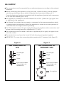
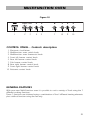
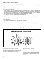
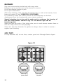
D 90 G
Professional
COOKER
INSTALLATION and SERVICE INSTRUCTIONS
USE and CARE INSTRUCTIONS
distributed by
PA R E X
Industries Ltd
Dear Customer,
Thank you for having purchased and given your
preference to our product.
The safety precautions and recommendations reported
below are for your own safety and that of others. They
will also provide a means by which to make full use of
the features offered by your appliance.
Please keep this booklet in a safe place. It may be
useful in future, either to yourself or to others in the
event that doubts should arise relating to its operation.
This appliance must be used only for the task it has
explicitly been designed for, that is for cooking
foodstuffs. Any other form of usage is to be considered
as inappropriate and therefore dangerous.
The manufacturer declines all responsibility in the
event of damage caused by improper, incorrect or
illogical use of the appliance or be faulty installation.
PRODUCT LABEL
2
FIRST TIME USE THE OVEN
It is advised to follow these instructions:
Clean the interior of the oven with cloth soaked in water and detergent (neutral)
then dry carefully.
■ Fit the wire racks as described at chapter “Use and care”.
■ Insert shelves and tray.
■ Switch on the empty oven on max to eliminate grease tracks from the heating
elements.
■
IMPORTANT PRECAUTIONS AND RECOMMENDATIONS FOR
USE OF ELECTRICAL APPLIANCES
Use of any electrical appliance implies the necessity to follow a series of fundamental
rules. In particular:
■ Never touch the appliance with wet hands or feet;
■
do not operate the appliance barefooted;
do not allow children or other incapable people to use the appliance
without supervision.
The manufacturer cannot be held responsible for any damages caused by improper,
incorrect or illogical use of the appliance.
■
3
IMPORTANT PRECAUTIONS AND RECOMMENDATIONS
After having unpacked the appliance, check to ensure that it is not damaged.
In case of doubt, do not use it and consult your supplier or a professionally qualified technician.
Packing elements (i.e. plastic bags, polystyrene foam, nails, packing straps, etc.) should not
be left around within easy reach of children, as these may cause serious injuries.
4
■
Do not attempt to modify the technical characteristics of the appliance as this
may become dangerous to use.
■
Do not carry out cleaning or maintenance operations on the appliance without
having previously disconnected it from the electric power supply.
■
After use, ensure that the knobs are in off position.
■
Do not allow children or other incapable people to use the appliance without
supervision.
■
During and after use of the cooker, certain parts will become very hot. Do not
touch hot parts.
■
Keep children away from the cooker when it is in use.
■
Some appliances are supplied with a protective film on steel and aluminium parts.
This film must be removed before using the appliance.
■
Fire risk! Do not store flammable material in the oven, and in the accessory
drawer.
■
Make sure that electrical cables connecting other appliances in the proximity of
the cooker cannot come into contact with the hob or become entrapped in the
oven door.
■
Do not line the oven walls with aluminium foil. Do not place baking trays or the
drip tray on the base of the oven chamber.
■
The manufacturer declines all liability for injury to persons or damage to property
caused by incorrect or improper use of the appliance.
■
IMPORTANT NOTE: This appliance shall not be used as a space
heater, expecially if installed in marine craft or caravans.
INSTALLATION
CAUTION:
■
This appliance must be installed in accordance with these installation
instructions, local gas fitting regulations, municipal building codes,
water supply regulations, electrical wiring regulations, AS5601 / AG 601
- Gas Installations and ony other relevant statutory regulations.
■
This appliance shall be only be serviced by authorized personnel.
■
This appliance is to be installed only by an authorised person.
■
Incorrect installation, for which the manufacturer accepts no
responsibility, may cause personal injury of damage.
■
Always disconnect the cooker from mains power supply before carrying
out any maintenance operations or repairs.
■
In the room where the cooker is installed, there must be enough air to
allow the gas to burn correctly, according to the current local
regulations.
5
ELECTRICAL REQUIREMENTS
■
■
■
■
■
■
■
The appliance must be connected to the mains checking that the voltage
corresponds to the value given in the rating plate and that the electrical
cable sections can withstand the load specified on the plate.
The plug must be connected to an earthed socket in compliance with safety
standards.
If the appliance is supplied without plug, fit a standard plug which is
suitable for the power consumed by the appliance.
The appliance must be connected directly to the mains placing an omnipolar
switch with minimum opening between the contacts of 3 mm between the
appliance and the mains.
The power supply cable must not touch the hot parts and must be
positioned so that it does not exceed 50°C above ambient.
Once the appliance has been installed, the switch or socket must always be
accessible.
If the power supply cable is damaged it must be substituted by a suitable
cable according to current electrical regulations.
N.B. The connection of the appliance to earth is mandatory.
If the installation requires alterations to the domestic electrical system call a qualified
electrician.
He should also check that the socket cable section is suitable for the power drawn by
the appliance.
Replacing the power cord must be done by a qualified electrician in
accordance with the instructions supplied by the manufacturer and in
compliance with established electrical regulations.
6
CLEARANCES
Installation clearances and protection of combustible surfaces shall comply with
the requirements of AS5601 / AG 601 - Gas installation.
Installation shall comply with the Dimension in Fig 1 bearing in mind that
Overhead Clearances
In no case shall the clearances between the highest part of the cooker be less
than 600mm or for an ovehead exhaust fan 750mm. AII other downward facing
combustible surfaces less than 600mm above the cooker surface shall be protected
for the full width of the cooking surface in accondance with the standards noted
above. In no case shall the clearance be less than 450mm
Side Clearances
Where the dimensions from the periphery of the nearest burner to any vertical
combustible surface is less than 200mm the surface shall be protected in
accordance with the standards to a height of not less than 150mm above the
cooking surface for the full width or depth of the cooking surface
Protection of combustible surfaces.
The standards above specify that where required protection shall ensure that the
surface temperature of the combustible surface does not exceed 50°C above room
temperature.
500 mm
450 mm
650 mm
Figure 1
300 mm
7
ANTI-TILT BRACKET
Fixing the anti-tilt bracket:
■
After you have located where the cooker is to be positioned mark, on the wall, the
place where the 2 screws of the anti-tilt bracket have to be fitted. Please follow the
indications given in the drawing below.
■
Make two holes of diameter 8mm diameter on the wall and insert the plastic plugs.
■
Attach the anti-tilt bracket loosely by means of 2 screws.
■
Move the cooker to the wall and adjust the height of the anti-tilt bracket so that it can
engage in one slot of the cooker back.
■
Attach the anti-tilt bracket tight.
■
Push the cooker against the wall so that the anti-tilt bracket is fully inserted in one slot
of the cooker back.
Figure 2
=
8
=
ASSEMBLING THE BACKGUARD
1. Insert the side supports S and D into the backguard B (see fig. 3)
2. Insert the backguard group into the support guides in the cooker
3. The backguard can be removed for cleaning or fixed with a screw through the
hole C.
D
B
S
C
Identification
label
Figure 3
When you open the
bottom oven door the
indentification label is
at the bottom right
hand side.
9
USE and CARE
CAUTION:
■
This appliance must be used only for the task it has explicitly been designed for,
that is for cooking foodstuffs. Any other form of usage is to be considered as
inappropriate and therefore dangerous.
■
Do NOT place combustible materials or products on this appliance at any time.
■
Do NOT spray aerosols in the vicinity of this appliance while it is in use.
USING THE OVEN FOR THE FIRST TIME
Clean the inside of the oven with a cloth soaked in water and neutral detergent
and dry thoroughly.
■ Slide in the catalytic liners and wire racks on the oven wall as in Fig. 4. Position
the shelf and tray as per Fig. 5.
■
■
To eliminate traces of grease in manifacture it is necessary to pre-heat the oven
at the maximum temperature, for 60 minutes in the
position, for 30 minutes
in the
position and for another 15 minutes in the
position.
Figure 4
10
Figure 5
GAS SUPPLY:
■
The connection must be executed by an authorised person according to the relevant
standards.
■
Before connecting the appliance to the gas main, mount the brass conical adaptor
onto the gas inlet pipe, upon which the gasket has been placed (figures 6-7).
Conical adaptor and gasket are supplied with the appliance (packed with conversion
kit for use with Natural gas or LPG).
■
This appliance is suitable for use with Natural Gas or LPG. (Check the “gas type” sticker attached to the appliance).
■
For Natural Gas models the gas supply is connected to the pressure regulator which
is supplied with the appliance. Adjust the regulator to obtain a test point pressure of
1 kPa with the two largest burners operating.
■
For LPG models connect the gas supply directly to the appliance inlet connection and
ensure that the supply pressure is regulated to 2.75 kPa.
■
The connection must be made at the rear of appliance (left or right); the pipe do not
cross the cooker.
■
The terminal not used must be closed off with the plug and gasket supplied.
■
IMPORTANT: To screw the connecting tube operate with 2 spanners (side figure 9).
Figure 6
Figure 7
Gas connection for
LPG
Gas connection for
NATURAL GAS
Gas inlet pipe
Gas inlet pipe
Nipple
Nipple
Gasket
Gasket
Brass conical adaptor
Brass conical adaptor
(Thread tight: use
suitable seal)
(Thread tight: use
suitable seal)
Gas regulator
11
1. After connecting the gas supply, check the piping and connections for leaks using
a soap and water solution. The presence of bubbles indicates a leak, tighten or
replace connections as appropriate.
2. Adjust the test point pressure or supply pressure to the value which is appropriate
for the gas type.
3. The operation of the appliance must be tested before leaving.
4. Turn on the appliance gas controls and light each burner individually and in combination. Check for a well defined blue flame without any yellow tipping. If any
abnormality is evident then check that the burner cap is located properly and the
injector nipple is aligned correctly.
5. Check the minimum burner setting by quickly rotating the gas control knob from
the maximum to the minimum position, the flame must not go out. If adjustment is
required carry out the “minimum burner setting adjustment" procedure described
6. If satisfacfory performance cannot be obtained isolate the appliance and contact
the local gas authority for advice and assistance.
Figure 8
Figure 9
Plug
12
INJECTORS REPLACEMENT
This appliance is suitable for use with natural gas or LPG (check the “gas type” sticker
attached to the appliance). A label stating the type of gas used after replacing the
injectors should replace the existing label. The nominal gas consumption and injector
size details are provided in table at page 18.
To replace the injectors it is necessary to lift the cooktop and proceed as follows:
■ Remove the backguard “E” (Fig. 10).
■
Remove pan supports and burners from the cooktop.
■
Unscrew the two screws “B” and remove the sockets (Fig. 10).
■
Unscrew the two screws “C” and remove the two side trims and joints pulling
upwards.
■
Pull forwards the hobtop to release it, then lift following arrow “D” (Fig. 10).
■
Hold the hobtop open by a support.
■
Fully raise the adjusting air tube A (fig. 11) in order to easily reach the injector.
■
Using a 7 mm A/F angled spanner, remove the injector from its housing and replace
it one according to the kind of gas (see following tables - page 16).
Figure 10
G
B
V
E
D
B
E
D
13
PRIMARY AIR ADJUSTMENT OF THE BURNERS
By operating the screw “M”, reset the air adjuster “A” according to the instructions
see “Injector table”, where the distance between injector and air adjuster is
recommended (in mm).
Before refixing the hob top, set the burners on their sites and light them in order
to check whether the flames are correct, as per the specifications given above.
In case of uncorrect flame, lift or lower the air adjuster.
Figure 11
M
J
A
Flame faulty in
primary air
Flame correct
Flame with excess
primary air
long, yellow and trembling
clear interior blue cone
short and sharp
too blue interior cone
tending to detach
CAUSE
air regulating tube,
too closed
14
correct distance
of the tube
air regulating tube,
too open
MINIMUM BURNER SETTING ADJUSTMENT
In the minimum position the flame must have a length of about 4 mm and must
remain lit even when turned quickly from the maximum position to minimum.
The flame adjustment is done in the following way:
■ Turn on the burner
■ Tum the tap to the MINIMUM position
■ Take off the knob
■ With a small flat screwdriver turn the screw “F” (fig. 12) to the correct regulation.
Normally for LPG, the regulation screw is tightened up fully.
Figure 12
F
15
TABLE FOR THE CHOICE OF THE INJECTORS
Test Point Pressure [kPa]
Natural gas
Propane
1,0
2,75
kW
kW
mm
Primary air
shutter
opening
[mm]
mm
Primary air
shutter
opening
[mm]
Auxiliary (A)
0,9
0,25
0,83
1
0,5
3
Semi-rapid (SR)
1,7
0,44
1,15
4
0,67
6
Double ring (DR)
3,4
0,85
1,6
15
0,92
Fully open
Fish burner (FB)
N = 2,8
LPG = 3,06
0,85
1,42
15
0,90
Fully open
Nominal
Power
BURNER
INCREASE
BURNERS
Reduced
power
Injector
Orifice Dia.
OF AIR NECESSARY FOR GAS COMBUSTION
Injector
Orifice Dia.
(2 m3/h x kW)
Air necessary for combustion [m3/h]
Auxiliary (A)
2,00
Semi-rapid (SR)
3,80
Double ring (DR)
6,90
Fish burner (FB)
7,10
LUBRICATION OF THE GAS TAPS
If the gas tap becomes stiff, it is necessary to dismantle it carefully and clean it with petroleum
spirit. Specialist high temperature resistant grease should be used to lubricate the tap before
replacing.
The operations must be carried out by an authorised person.
16
GAS HOB
Figure 13
2
3
4
1
GAS BURNERS
1.
2.
3.
4.
5.
Double ring burner (DR)
Semi-rapid burner (SR)
Fish-burner (FB)
Semi-rapid burner (SR)
Auxiliary burner (A)
5
Natural Gas
Mj/hr
Propane
Mj/hr
12,2
6,1
10,1
6,1
3,0
10,8
5,6
11,0
5,6
3,1
17
LIGHTING GAS BURNERS
FITTED WITH SAFETY VALVE DEVICE AND ELECTRONIC IGNITION
■
Check that the electricity is
switched on to allow spark ignition.
■
Make sure that all controls are
turned to zero.
■
The gas flow to the burner is
controlled by a taps with safety
valve device. If the burner flame
should go out for some reason,
the safety valve will automatically
stop the gas flow. The switch of
the electric ignition is incorporated in the knobs.
Figure 14
■
You control the flow by turning the knob indicator to line up with the following
symbols:
– Symbol
18
●
: tap closed (burner off)
– Symbol
: High (maximum)
– Symbol
: Low (minimum)
■
To ignite automatically, simply push the required knob down and turn it to maximum, keep the knob down until the burner lights. When the flame is lit, wait
for about ten second with the knob down (safety valve activation delay).
■
You can control the temperature by the knob to “full on” from “reduced rate”.
■
To switch off, turn the knob clockwise until you hear the safety click.
■
Note that, if you are using a burner at the minimum setting, you turn the knob
clockwise past the maximum setting before reaching the off position.
■
Whenever the lighting of the burners will result difficult due to peculiar conditions. If when lighting any of the burners an anormal flame appears, switch
that the burner off and relight using the minimum setting.
■
If the flame is still different from normal, turn the burner off and consult your
DeLonghi service agent.
■
In the case of a mains failure light the burner with a match or lighted taper.
CHOICE OF BURNER
The burner must be chosen according to the diameter of the pans and energy
required.
Burners
Pan diameter
Auxiliary
Semi-rapid
Double ring
Fish-burner
Wok
16 cm
16 to 22 cm
up to 30 cm
from 12x30 to 18x40 cm
max 36 cm
Figure 15
Saucepans with handles which are excessively heavy, in relationship to the weight
of the pan, are safer as they are less likely to tip.
Pans which are positioned centrally on burners are more stable than those which
are offset.
It is far safer to position the pan handles in such a way that they cannot be
accidentally knocked.
When deep fat frying fill the pan only one third full of oil.
DO NOT cover the pan with a lid and DO NOT leave the pan unattended.
In the unfortunate event of a fire, leave the pan where it is and turn off all
controls.
Place a damp cloth or correct fitting lid over the pan to smother the flames.
DO NOT use water on the fire.
Leave the pan to cool for at least 30 minutes.
19
CORRECT USE OF DOUBLE-RING BURNER
20
■
The flat-bottomed pans are to be placed directly onto the pan-support.
■
To use the WOK you need to place the proper stand in order to avoid any faulty
operation of the wok burner.
Figure 16
Figure 17
WRONG
CORRECT
MULTIFUNCTION OVEN
Figure 18
A
U
T
O
1
2
3
4
5
7
8
9
10
CONTROL PANEL - Controls description
1.
2.
3.
4.
5.
7.
8.
9.
10.
Electronic clock/alarm
Multifunction oven switch knob
Multifunction oven thermostat knob
Front left burner control knob
Rear left burner control knob
Fish burner control knob
Rear right burner control knob
Front right burner control knob
Rotisserie control knob
GENERAL FEATURES
With your new Multi-Function oven it is possible to cook a variety of food using the 7
different cooking functions.
These 7 functions are obtained using a combination of the 4 different heating elements
plus a defrost function using the fan only.
21
OPERATING PRINCIPLES
Heating and cooking in the MULTI-FUNCTION oven are obtained in the following
ways:
a. by normal convection
The heat is produced by the upper and lower heating elements.
b. by forced convection
A fan sucks in the air contained in the oven muffle, which sends it through the
circular heating element and then sends it back through the muffle. Before the
hot air is sucked back again by the fan to repeat the described cycle, it envelops
the food in the oven, provoking a complete and rapid cooking.
It is possible to cook several dishes simultaneously.
c. by semi-forced convection
The heat produced by the upper and lower heating elements is distributed
throughout the oven by the fan.
d. by radiation
The heat is radiated by the infra red grill element.
e. by radiation and ventilation
The irradiated heat from the infra red grill element is distributed throughout the
oven by the fan.
Figure 19
FUNCTION SELECTOR KNOB
THERMOSTAT KNOB
Rotate the knob clockwise to set the oven
for one of the following functions.
This only sets the cooking temperature
and does not switch the oven on.
Rotate clockwise until the required
temperature is reached (from 50 to
225°C).
22
OVEN LIGHT
By setting the knob to this position, only the oven light comes on (15 W).
It remains on in all the cooking modes.
TRADITIONAL BAKE
The upper and lower heating elements come on. The heat being dispersed by
natural convection. The temperature range must be set between 50°C and 225°C
using thermostat.
The oven must be preheated before cooking.
Ideal for:
Food that requires the same degree of cooking both inside and out, for example
roasts, spare pork ribs, meringues etc.
GRILLING
The infrared grill element at the top of the oven comes on. The heat is dispersed by
radiation.
Use with the function knob set to
, the thermostat from 50 to 200°C and with the
oven door closed.
For cooking hints, see the chapter “USE OF THE GRILL”.
Ideal for:
Intense grilling, browning, cooking au gratin and toasting etc.
It is recommended that you do not grill for longer than 30 minutes at any
one time.
Attention: the oven door becomes very hot during operation.
Keep children away.
DEFROST
Only the oven fan comes on. Use with the thermostat knob set to “0” - other temperature have no effect. The food is thawed by ventilation without heating.
Ideal for:
Quick thawing of frozen foods; one kg requires approximately 1 hour.
Thawing times vary according to the quantity and type of food to be thawed.
23
FAN FORCED
The circular element and fan come on. The heat is dispersed by forced convection and
the temperature can be varied to between 50° and 225°C via the thermostat knob.
The oven does not require preheating.
Recommended for:
Food which has to be well-cooked outside and soft or rosy inside, for example lasagne,
lamb, roast beef, whole fish etc.
FAN GRILL
Both the grill and the fan come on. Most of the cooking is done by grilling and then
the hot air circulated around the oven. The oven door should be kept closed.
The temperature can be set between 50°C and 175°C maximum.
The oven should be preheated for 5 minutes before cooking. For further cooking hints
see “GRILLING AND COOKING AU GRATIN”).
Ideal for:
Quick sealing in of food juices for example such as hamburger, chicken pieces, chops.
It is recommended that you do not grill for longer than 30 minutes at any
one time.
Attention: the oven door becomes very hot during operation.
Keep children away.
MAINTAINING TEMPERATURE AFTER COOKING OR
SLOWLY HEATING FOODS
The upper element, the circular element and the fan come on.
The heat is circulated by forced convection with greater intensity in the upper part.
The temperature can be set to between 50° and 140°C via the thermostat knob.
Recommended for:
Keeping food warm after any type of cooking. Slow heating of cooked food.
MULTI-FUNCTION
The upper and lower heating elements come on and the fan come on - the heat from
the element being circulated by the fan.
The temperature range can be set to between 50° and 225°C using the thermostat.
Idea for:
Large bulky quantities of food that require even cooking throughout for example large
roasts, turkey, roast turkey, cakes etc.
24
COOKING ADVICE
STERILIZATION
Sterilization of foods to be conserved, in full and hermetically sealed jars, is done in the
following way:
a. Set the switch to position
.
b. Set the thermostat knob to position 185 °C and preheat the oven.
c. Fill the dripping pan with hot water.
d. Set the jars onto the dripping pan making sure they do not touch each other and
the door and set the thermostat knob to position 135 °C.
When sterilization has begun, that is, when the contents of the jars start to bubble,
turn off the oven and let cool.
Check your recycle book for full instructions.
REGENERATION
Set the switch to position
and the thermostat knob to position 150° C.
Bread becomes fragrant again if wet with a few drops of water and put into the oven
for about 10 minutes at the highest temperature.
SIMULTANEOUS COOKING OF DIFFERENT FOODS
The MULTI-FUNCTION oven set on position
consents a simultaneous
heterogeneous cooking of different foods. Different foods such as fish, cake and
meat can be cooked together without mixing the smells and flavors together. This
is possible since the fats and vapors are oxidized while passing through the
electrical element and therefore are not deposited onto the foods.
The only precaution to follow are:
– The cooking temperatures of the different foods must be as close to as possible,
with a maximum difference of 20° - 25 °C.
– The introduction of the different dishes in the oven must be done at different
times in relation to the cooking times of each one.
The time and energy saved with this type of cooking is obvious.
25
GRILLING AND “AU GRATIN”
Grilling may be done without the roasting jack on position
of the switch,
because the hot air completely envelops the food that is to be cooked.
Set the thermostat to position 175 °C and after having preheated the oven, simply
place the food on the rack.
Close the door and let the oven operate with the thermostat on position 175 °C,
until grilling is done.
Adding a few dabs of butter before the end of the cooking time gives the golden
“au gratin” effect.
It is recommended that you do not grill for longer than 30 minutes at
any one time.
Caution: the oven door becomes very hot during operation. Keep children
well out of reach.
ROASTING
To obtain classical roasting, it is necessary to remember:
– that it is advisable to maintain a temperature between 180° and 200 °C.
– that the cooking time depends on the quantity and the type of foods.
USE OF THE GRILL
Preheat the oven for about 5 minutes.
Introduce the food to be cooked, positioning the rack as close to the grill as
possible.
The dripping pan should be placed under the rack to catch the cooking juices
and fats.
Grilling with the oven door closed.
Do not grill for longer than 30 minutes at any one time.
Caution: the oven door becomes very hot during operation. Keep children
well out of reach.
26
ROTISSERIE
(Fig. 21)
This is used for spit roasting under the
grill and comprises:
– an electric motor fitted to the rear of
the oven
– a stainless steel skewer provided with
slide-out heatless handgrip and two
sets of adjustable forks
– a skewer support to be fitted in the
middle runner.
The rotisserie motor is operated by the
oven switch (Fig. 20).
Figure 20
USE OF THE ROTISSERIE
– Insert the tray into the lowest rack holders of the oven and insert the rod support
into the intermediate rack holders.
– Put the meat to be cooked onto the rod, being careful to secure it in the center with
the special forks.
– Insert the rod into the side gear opening “P”
– Remove the grip “H” by turning it to the left.
– Insert completely the rotisserie support; the shaft “S” must be inserted in the spit
motor collar “G”.
The rotation direction of the rotisserie can be either clokwise or counter-clockwise.
Figure 21
S
P
G
H
27
RECOMMENDED COOKING TEMPERATURE
Food
°C
°F
Gas
Mark
Shelf
Position*
Cooking
Time (approx)
CAKES
Victoria sandwich
Small cakes/buns
Maidera cake
Fruit cake
Rich fruit cake
Scones
190
190
180
170
150
225
375
375
350
325
300
425
5
5
4
3
2
8-9
2 or 3
1 and 2
2 or 3
3
3 or 4
2
20-25 mins
15-20 mins
20 mins
13/4 hours
21/2 hours
8-10 mins
PASTRY
Puff
Short crust
Plate tarts
Quiches and flans
225
200
200-210
200-210
425
400
400-410
400-410
8-9
6
6
6
2
2
1 or 2
1 or 2
10-20 mins
20-30 mins
30-35 mins
40-45 mins
225
220
230
425
425
450
7-8
7
8
2
1 or 2
2
35-55 mins
15-20 mins
20 mins
190
190
190-200
190
190
180
150-170
375
375
375-400
375
375
350
300-325
5
5
5-7
5
5
4
2-3
2 or 3
2 or 3
2 or 3
2 or 3
2 or 3
2 or 3
2 or 3
20 mins/lb + 20 mins
25-30 mins/b + 25 mins
30 mins/lb + 30 mins
30 mins/b + 30 mins
30 mins/b + 30 mins
18-20 mins/b + 20 mins
11/2 2 hours
YEAST
Bread loaf
Bread rolls
Pizza dough
ROAST MEAT
Beef – Medium
Lamb
Pork
Veal
Chicken
Turkey up to 10lb
Stews/casseroles
N.B. For fan ovens reduce the temperature
by 10-20°C. For any dish taking one hour or
over to cook, reduce the cooking time by 10
minutes per hour.
28
* Shelf positions have been counted from
the top of the oven to the base.
A fan oven creates more even temperature
throughout, therefore the shelf positions are
not as critical.
How to use the Electronic Clock
The electronic programmer is a device
with the following functions:
– 24 hours clock with illuminated display
– Timing of oven cooking with automatic
switch-off (max. 99 minutes).
ELECTRONIC CLOCK
Upon immediate connection of the oven
or after a mains failure, three zeros will
flash on the programmer panel.
To set the clock it is necessary to push the
button and then, within 7 seconds, the
or
button until you have set the
correct time.
The clock will show zero after a mains
failure.
Attention: When the programmer display
shows three flashing zeros the oven
cannot be switched on.
The oven can be switched on when the
symbol
is shown in the display.
SETTING THE FREQUENCY
OF THE ALARM SOUND
The selection from 3 possibilities of
sound can be made by pressing the
button.
Figure 22
A
U
T
O
COOKING WITH
AUTOMATIC SWITCH-OFF
The aim of this function is to automatically
stop the cooking after a pre programmed
time, for a maximum period of 99 minutes.
To set the cooking time, push the
or
button until you obtain the desired
time in the display. The symbol AUTO
will be shown in the display. Then you
adjust the oven thermostat knob
according to the required temperature.
The oven will immediately start to operate
and will work for the pre programmed
time. The display shows the count down.
Clock time can be displayed by pressing
the
button. Once the time has
elasped, the oven will switch off
automatically, the symbol AUTO will go
off and an intermittent buzzer, lasting 7
minutes, will start; this can be stopped by
pressing the
buttons.
Important: Before the buzzer is
stopped switch off the oven manually.
To cancel the cooking program at any time
press the
and
buttons together
and release the
button first.
ELECTRONIC ALARM
The programmer can be used as an alarm
only for a maximum period of 99 minutes.
To set the alarm, push the
or
button until you obtain the desired time in
the display. Once the time has elasped,
an intermittent buzzer, lasting 7 minutes,
will start; this can be stopped by pressing
the
button.
Attention: If the bottom oven is
switched on when the buzzer starts, it
will be automatically switched off. For
it to operate furtherly you have to stop
the buzzer by pressing the
button.
29
Cleaning and Maintenance
GENERAL ADVICE
■
■
■
■
■
Before you begin cleaning, you must ensure that the appliance is
switched off.
It is advisable to clean when the appliance is cold and especially when cleaning
the enamelled parts.
Avoid leaving alkaline or acidic substances (lemon juice, vinegar, etc.) on the
surfaces.
Avoid using cleaning products with a chlorine or acidic base.
Do not use a steam cleaner because the moisture can get into the appliance
thus make it unsafe.
ENAMELLED PARTS
All of the enamelled parts must be washed only with a sponge and soapy water
or with non-abrasive products.
Dry, preferably, with deer skin.
STAINLESS STEEL
The stainless steel parts should be rinsed with water and dried with a soft, clean
cloth or chamois. In case of difficult spots, use normal non abrasive detergents
available on the market or else a little warm vinegar.
CLEANING THE HOB
Spillage on the hob can usually be removed by a damp soapy cloth. More
obstinate stains can be removed by rubbing gently with a soapy scouring pad or
mild household cleaner.
30
OVEN
The oven with smooth enamel must be cleaned after every use, using suitable
products. Please note that after using the oven for 30 minutes on the highest
temperature eliminates most grime reducing it to ashes.
Do not use abrasive substances to clean the oven.
Advice for use and maintenance of catalytic panels
The catalytic panels are covered with special microporous enamel which absorbs
and does away with oil and fat splashes during normal baking over 200°C.
If, after cooking very fatty foods, the panels remain dirty, operate the oven “idling”
on max temperature for about 30 minutes. These panels do not require to be
cleaned, however it is advised to periodically remove them from the oven (at least
the side panels) and to wash them with tepid soapy water and then wipe off with
a soft cloth.
DO NOT CLEAN OR WASH THEM WITH ABRASIVE PRODUCTS OR WITH
PRODUCTS CONTAINING ACIDS OR ALKALIS.
The side panels are reversible and when the catalytic microporous enamel
degrades, they can be turned to the other side.
31
BURNERS
They can be removed and washed only with soapy water.
Detergents can be used but must not be abrasive or corrosive.
Do not use abrasive sponges or pads.
Do not put in dishwasher.
After each cleaning, make sure that the burner-caps, as well as the burners, have
been well wiped off and CORRECTLY POSITIONED.
It is essential to check the correct position of the burner-caps as the least
displacement from the housing may cause serious problems.
Special attention has to be paid in order not to exchange the housing of
the two small burners shown in fig. 23. The burner caps can be
interchangeable.
Make sure that the probe of the safety valve, near to each burner, remains clean so
that the safety valves can work properly.
Check also that the electrodes for ignition be always clean in order to ensure a
regular spark shooting.
GAS TAPS
If a tap becomes stiff, do not force; contact your local DeLonghi Service Agent.
Figure 23
Burner-cap ring
partially drilled
32
Burner-cap ring
fully drilled
REMOVAL OF THE INNER GLASS DOOR PANEL
– The inner glass door panel can easily be removed for cleaning by unscrewing
the four screws (fig. 24).
– When re-assembly ensure that the inner glass is correctly positioned and do not
over tighten the screws.
Figure 24
DISHWARMER COMPARTMENT
– The dishwarmer compartment is accessible through the pivoting panel.
Attention: Do not store flammable material in the oven, or the
dishwarmer compartment.
Figure 25
33
GRILL HEATING ELEMENT
The heating element is self-cleaning and does not require maintenance.
REPLACING THE OVEN LIGHT
Before any maintenance is started involving electrical parts of the
appliance, it must be disconnected from the power supply.
The bulb must be a type resistant to high temperatures (300° C).
OVEN TRAY
The oven tray must be correctly placing on its wire shelf support (fig. 26)
then insert into the side runners (fig.
27)
Figure 27
34
Figure 26
DISMANTLING THE DOOR
Figure 28a
Please operate as follows:
●
●
●
●
Open the door completely.
The swivel retainers of the rh and
lh hinges (fig. 28a) are hooked
onto the metal bar above them
(fig. 28b).
Lift the oven door slightly. The
noch on the bottom of the hinge
will disengage (fig. 28c).
Now pull the oven door forwards
off the appliance. Release both
hinge sections from the slots (fig.
28d).
Figure 28b
DOOR ASSEMBLY
●
Grip the door (as indicated in
figure 28) and refit it in reverse
order of removing procedure.
Figure 28c
Figure 28
Figure 28d
35
Fitting the adjustable feet
Figure 29
The adjustable feet must be fitted
to the base of the cooker before
use.
Rest the rear of the cooker an a
piece of the polystyrene packaging
exposing the base for the fitting of
the feet.
Figure 30
WARNING
When raising cooker to
upright position always ensure
two people carr y out this
manoeuvre to prevent damage
to the adjustable feet (fig. 30).
36
Figure 31
WARNING
Be carefull: do not lift the cooker
by the door handle when raising
to the upright position (fig. 31).
WARNING
When moving cooker to its final position DO NOT DRAG (fig. 32).
Lift feet clear of floor (fig. 30).
Figure 32
Figure 33
LEVELLING THE COOKER
The cooker may be levelled by screwing the lower ends of the feet IN or
OUT (fig. 33).
37
WIRING DIAGRAM
S1
TM
F1
1a
1
2a
2
3a
3
4a
4
5a
5
6a
6
7a
7
8a
8
9a
9
10a
10
11a
11
F2
1
1a
N/7
P1
1
P2
2
L/8
PR
GIR
LF
PA
A
C
CIR
G
V
S
Cod. 1131216
T
TL
M
L
N
ELECTRIC DIAGRAM KEY
F1
F2
TM
LF
PR
C
G
V
S
CIR
PA
A
GIR
TL
S1
M
T
38
Oven switch
Rotisserie switch
Thermostat
Oven lamp
Electronic clock/End cooking timer
Top element
Grill element
Fan
Bottom element
Circular element
Ignition switches group
Ignition coil
Rotisserie
Thermolimiter
Thermostat pilot lamp
Terminal block
Earth plant
39
ß7
Ed. 3 - 1101630