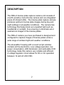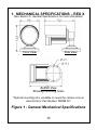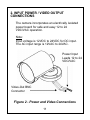
1
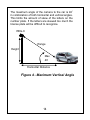
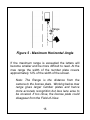
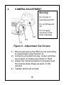
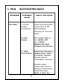
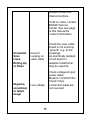
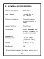
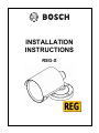
INSTALLATION INSTRUCTIONS REG-X MAN-REG-X-08 IMPORTANT SAFETY INSTRUCTIONS 1. Read these instructions. 2. Keep this instruction. 3. Heed all warnings. 4. Follow all instructions. 5. Clean only with dry cloth. 6. Do not block any ventilation openings. Install in accordance with manufacturer instructions. 7. Do not install near any heat sources such as radiators, heat register s, stoves or other apparatus (including am plifiers) that produce heat. 8. Do not defeat the safety purpose of the polarized or grounding-type plug. A polarized plug has two blades with one wider than the other. A grounding type plug has two blades and a third grounding prong. The wide blade or the third prong is provided for your safety. If the provided 2 plug does not fit into your outlet, consult an electrician for replacement of the obsolete outlet. 9. Protect the power cord from being walked on or pinched particularly at plugs, convenience receptacles, and the power where they exit from the apparatus. 10. Only use attachments/accessories specified by the manufacturer. 11. Use only with the cart, stand, tripod, bracket, or table specified by the manufacturer, or sold with the apparatus. When a cart is used, use caution when moving the cart/apparatus combination to avoid injury from tip-over. 12. Unplug this apparatus during lightning storms or when unused for long periods of time. 13. Refer all servicing to qualified service personnel. Servicing is required when the apparatus has been damaged in a way, such as power-supply cord or plug is damaged, liquid has been spilled or objects have fallen into the apparatus, the apparatus has been exposed to rain or moisture, does not operate normally, or has been dropped. 3 IMPORTANT For best results, please read this Instruction Booklet prior to installing the REG-X camera. WARNING ! CSA Certified / UL Listed CLASS 2 power adaptors must be used in order to comply with electrical safety standards. Bosch Security Systems, Inc. will not be responsible for injuries or damages resulting from the improper installation or use of any product sold by Bosch Security Systems, Inc their agents, distributors or dealers. EU Directives covered by this declaration: 72/9/EC Low Voltage Directives 89/336/EEC Electromagnetic Compatibility Directive 4 NOTE: This equipment has been tested and found to comply with the limits for a digital device, pursuant to part 15 of the FCC rules. These limits are designed to provide reasonable protection against harmful interference in a residential installation. As part of it's normal operation this device can generate radio frequency energy and if not installed and used in accordance with the installation manual may cause interference to radio communications. However, there is no guarantee that interference will not occur on a particular installation. If the device does cause interference to radio or television reception the user is encouraged to try to correct the interference by one or more of the following measures: 1) Fit Ferrite beads on all cable to and from the power supply box, within the box walls. 2) Route the composite cable between the camera and the power supply in steel conduit piping over the entire run of the cable up to and including connection to a deep conduit base fitted under the camera and a conduit fitting adaptor in the wall of the PSU box. 3) Contact BOSCH Service Center for further advice. 5 INDEX – REG-X Camera Description………………………………………………...7 Unpacking………………………………………………....8 Parts List…………………………………………………..8 Items Required for Installation…………………………..8 Initial Preparations………………………………………..9 Guidelines………………………………………………....9 1. 2. 3. 4. 5. 6. Mechanical Specifications REG-X…………..…….10 Input Power / Video Output Connections…………11 Mounting Specification………..……………………12 Camera Adjustment………………………………...16 Troubleshooting Guide…...………………….……..17 General specifications…………..………….………20 6 DESCRIPTION The REG-X license plate capture camera unit consists of one IR-sensitive monochrome camera and one integrated panel of Infrared LEDs. The license plate capture camera produces optimum license plate images during day and night settings in all-weather conditions. The camera has technology that helps block out unwanted light such as headlamps or sunlight, thus ensuring no bloomed-out or washed-out images of the license plates. The REG-X camera you have purchased is designed and configured to capture images of license plates under a wide range of ambient light and weather conditions. The all-weather housing with a covert acrylic window contains all the electronics. Low voltage operation, low power consumption, LED illuminator, and solid-state CCD technology make this camera very reliable and efficient. A voltage regulator circuit allows for DC or AC operation between 12 and 24 VAC/VDC. 7 UNPACKING Care should be taken when unpacking the shipped unit. Check the parts list and confirm all items have been located. Inspect the equipment thoroughly to ensure nothing was damaged in transit. Contact BOSCH Service Center if a problem is noted, see the rear page of this booklet for contact numbers. PARTS LIST (items supplied with unit) - REG-X camera assembly Adjustment hex key Installation Instructions booklet ITEMS REQUIRED FOR INSTALLATION (not supplied with units) • • • Mounting hardware Mounting tools Proper power supply 8 INITIAL PREPARATIONS • Determine the operating voltage at the installation site. The camera‘s Voltage Regulator Board accepts both 12-24VDC and VAC input without change to internal connections. See Section 2, Input Power/Video Output Connections. • Determine the optimum location for the camera. See Section 3, Mounting Specification. • All cameras have been tested prior to shipment. To verify the camera is operational when connected to a power supply and monitor, a retro reflective license plate should be placed in view of the camera to see a license plate image otherwise the image may appear dark or black. Note: The camera has been optimized to capture vehicle license plates of moving vehicles under all lighting conditions. GUIDELINES The installation of the REG-X camera is explained in Sections 1 to 3. It is important that these steps are followed and practice proper installation procedures with proper safety equipment. 9 1. MECHANICAL SPECIFICATIONS – REG X (See Section 6 - General Specifications, for more information) Front View Side View Bottom View Showing mounting holes *Optional mounting kit is available to mount the camera onto an electrical box; Part Number: WZMB.001 Figure 1 - General Mechanical Specifications 10 2. INPUT POWER / VIDEO OUTPUT CONNECTIONS The camera incorporates an electrically isolated power board for safe and easy 12 to 24 VDC/VAC operation. Note: Input voltage is 12VDC to 24VDC for DC input. The AC input range is 12VAC to 24VAC. Power Input Leads 12 to 24 VDC/VAC Video-Out BNC Connector Figure 2 - Power and Video Connections 11 3. MOUNTING SPECIFICATION Caution: Install with appropriate screws to suit mounting surface. Select a suitable location protected from accidental damage, and tampering. Mounting location must not expose the REG-X camera to environmental conditions exceeding the camera’s specification. See page 20. Caution: Ensure the selected location is protected from falling objects, contact with moving objects, and accidental interference from personnel. Please follow all applicable building regulatory codes. The following installation guidelines must be followed: • Locate the camera such that it cannot be easily interfered with, either intentionally or accidentally. • Select a mounting surface capable of supporting the combined weight of the camera and mounting hardware under all expected conditions of vibration and temperature. • Secure all cabling. • When setting up the camera, it would be helpful to have a vehicle parked at the position you want to capture the license plate. 12 The REG-X units have a horizontal field of view of about 6ft – 8ft (1.8m – 2.4m) at the specified capture range distance for the REG-X as shown on Figure 3 below. Since most vehicles have license plates mounted in the center of the front or back and the normal width for a standard traffic lane in a controlled parking or access lane is 8ft to 10ft (2.4m – 3.0m) this ensures that the license plate is in view whatever the position of the vehicle within the lane. If the traffic lane is wider than 10ft (3m) it is advisable to implement traffic guides to control the vehicles moving through the lane. Model Ra REG-X nge 15ft – 25ft 4.5m – 7.6m Optimal Range* 20ft 6m Figure 3 - REG-X Range Chart * Optimal range calculated with a 6ft (1.8m) lane width for field of view to capture license plates of 120 pixels wide for North American license plates. Most DVR application can provide readable plates larger than 80 pixels depending on level of image compression set on DVR. 13 The maximum angle of the camera to the car is 40º in combination of both horizontal and vertical angles. This limits the amount of skew of the letters on the number plate. If the letters are skewed too much the license plate will be difficult to recognize. REG-X Range Height Max 40ْ Horizontal Distance Figure 4 - Maximum Vertical Angle 14 Range Figure 5 - Maximum Horizontal Angle If the maximum range is exceeded the letters will become smaller and be more difficult to read. At the max range the width of the number plate covers approximately 12% of the width of the screen. Note: The Range is the distance from the camera to the license plate. Working below max range gives larger number plates and hence more accurate recognition but less lane area to be covered. If too close, the license plate could disappear from the Field-of-View. 15 4. CAMERA ADJUSTMENT Warning! Do not pan or twist beyond 360° Do not tilt beyond 90° Do not apply excessive force when adjusting Figure 6 - Adjustment Set Screws 1) Mount and secure the REG-X unit according to specification (see Section 3). 2) Using the provided hex key, loosen all three set screws on bracket as shown in Fig 6. 3) Adjust the camera position to properly level the license plate image as seen on the monitor. 4) Tighten all the set screws. 16 5. TROU PROBLEM No Video BLESHOOTING GUIDE POSSIBLE CAUSE LIKELY SOLUTION 1. Power Supply Connection Check the input power connections at the terminal block, ensuring no wires are loose. Voltage Range The supply range is: 12 - 24VDC OR 12 – 24VAC. Measure the input voltage to the camera. 2. Video Connections Determine if the wiring polarity at the “Video Connector” terminal block is correct. Check BNC connector. If still no video, connect the camera directly to the monitor. Check the video signal. If okay, the 17 problem is with the interconnections. If still no video, contact BOSCH Service Center. See rear page of this manual for contact information. Horizontal Scan Lines, Rolling Up or Down Negative, scrambled, or faded image Ground Looping on video cable Low voltage 18 Check the coax cable shield is not touching “ground”, e.g. at the couplings. An electrically isolated circuit board or isolation transformer may be required. Check voltage at input power cable. Must be >12VDC/VAC. Check Video connection leads are not reversed. Safety and Precaution “Prolonged direct viewing of the REG-X camera product at any distance does not pose a hazard to the retina or cornea.” When mounting and installing the REG-X camera, make sure proper safety equipment and procedures are used and practiced. This is to ensure the camera installation will not potentially cause any harm to people around the area and also the installer will be safe while performing the installation. Only qualified personnel shall install Bosch Security System, Inc. product. Bosch Security System, Inc. will not be responsible for injuries or damages resulting from the improper installation or use of any product sold by Bosch Security System, Inc., their agents, distributors or dealers. 19 6. GENERAL SPECIFICATIONS Power Consumption: 6.5W max Input Voltage: 12 – 24 VDC or 12 – 24 VAC Enclosure (housing): Robust Aluminum extrusion (sealed to IP66) Viewing Window: Black Acrylic Dimensions: 98mm Diameter (3.8”) 219mm Length (8.6”) (Length includes bracket) Operational Temperatures: -30º C to + 55º C (-22º F to + 131º F) Weight: 1.24kg (2.73 lbs) Certification CE All specifications subject to change without notice. 20 Note: 21 Note: 22 Note: 23 Americas Bosch Security Systems, Inc. 850 Greenfield Road Lancaster, Pennsylvania 17601 USA Telephone+1 888-289-0096 Fax +1 585-223-9180 Email: [email protected] www.boschsecurity.us Europe, Middle East, Africa: Bosch Security Systems B.V. P.O. Box 80002 5600 JB Eindhoven, The Netherlands Phone: + 31 40 2577 284 Fax: +31 40 2577 330 [email protected] www.boschsecurity.com Asia-Pacific: Bosch Security Systems Pte Ltd 38C Jalan Pemimpin Singapore 577180 Phone: +65 6319 3450 Fax: +65 6319 3499 [email protected] www.boschsecurity.com © Bosch Security Systems, Inc. 2011; Data subject to change without notice.