1
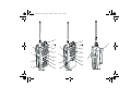
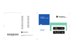
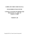
EN
SF
DE
GK
FR
RU
ES
CZ
IT
HU
PR
PL
DA
RO
SV
TU
NL
AR
MOTOROLA
COMMERCIAL SERIES
B A SIC USER GUIDE
CP1 4 0
6866550D01
6866550D01-A
MOTOROLA and the Stylized M Logo are registered in the U.S. Patent & Trademark Office.
All other product or service names are the property of their respective owners.
© Motorola, Inc. 2003
.
50D01_Inside Front Cover.fm Page 1 Friday, October 17, 2003 3:07 PM
2
2
3
1
3
4
5
11
P2
P1
3
2
1
4
7
14
4
5
11
10
13
1
5
8
0
6
P2
P1
7
6
8
8
*
9
CP180
7
10
9
#
6
9
CP160
12
SAFETY INFORMATION
BASIC USER GUIDE
This user guide covers the operation of the CP140,
CP160 and CP180 Portable Radios.
Contents
Radio Overview . . . . . . . . . . . . . . . . . . . . 2
Radio Controls . . . . . . . . . . . . . . . . . . . . . .
Audio Signal Tones . . . . . . . . . . . . . . . . . .
Programmable Buttons . . . . . . . . . . . . . . .
Menu Buttons (CP160/CP180). . . . . . . . . .
Menu Navigation Chart (CP160/CP180) . .
LCD Display and Icons (CP160/CP180) . .
2
3
3
4
5
6
Getting Started . . . . . . . . . . . . . . . . . . . . . 7
Battery Information. . . . . . . . . . . . . . . . . . . 7
Accessory Information . . . . . . . . . . . . . . . . 8
Turning the Radio On-Off. . . . . . . . . . . . . 11
Adjusting the Volume . . . . . . . . . . . . . . . . 11
Radio On Message (CP160/CP180) . . . . 11
Radio On Indicator (CP140). . . . . . . . . . . 12
Selecting a Radio Channel. . . . . . . . . . . . 12
Receiving a Call . . . . . . . . . . . . . . . . . . . . 13
Sending a Call . . . . . . . . . . . . . . . . . . . . . 13
Making a Selective Call (CP160/CP180) . 14
Receiving a Selective Call . . . . . . . . . . . . 14
Cancelling a Call . . . . . . . . . . . . . . . . . . . 14
Ending a Call . . . . . . . . . . . . . . . . . . . . . . 14
Before using this product, read the
operating instructions for safe usage
contained in the Product Safety and
RF Exposure booklet 6864117B25_
C a u t i o n enclosed with your radio.
!
ATTENTION!
This radio is restricted to occupational use only to
satisfy ICNIRP RF energy exposure requirements.
Before using this product, read the RF energy
awareness information and operating instructions in
the Product Safety and RF Exposure booklet
(Motorola Publication part number 6864117B25_) to
ensure compliance with RF energy exposure limits.
Computer Software Copyright
The products described in this manual may include copyrighted computer
programmes stored in semiconductor memories or other media. Laws in
the United States of America and other countries preserve for Motorola
Europe and Motorola Inc. certain exclusive rights for copyrighted computer
programmes, including the right to copy or reproduce in any form the
copyrighted computer programme. Accordingly, any copyrighted computer
programmes contained in the products described in this manual may not
be copied or reproduced in any manner without the express written
permission of the holders of the rights. Furthermore, the purchase of these
products shall not be deemed to grant either directly or by implication,
estoppel, or otherwise, any licence under the copyrights, patents, or patent
applications of the holders of the rights, except for the normal nonexclusive royalty free licence to use that arises by operation of the law in
the sale of the product.
1
English
BASIC USER GUIDE
CP140_160_180_BUG.fm Page 1 Wednesday, November 5, 2003 3:13 PM
CP140_160_180_BUG.fm Page 2 Tuesday, November 11, 2003 9:11 AM
BASIC USER GUIDE
RADIO OVERVIEW
Radio Controls
The numbers below refer to the illustrations on the
inside front and rear covers.
1. Push-to-talk (PTT)
Press and hold down this button to talk;
release it to listen.
2. On-Off / Volume Knob
Used to turn the radio on or off, and to adjust the
radio’s volume.
3. Channel Selector Knob
Used to switch the radio to different channels.
4. LED Indicators
Indicate radio status:
Green: Solid during power up routine; off after
successful power up; flashing when scanning.
Red: Solid - transmitting; Flashing when transmitting - low battery:
Flashing - channel is busy receiving.
Yellow: Solid when radio is in monitor mode,or
is sending a selective call or call alert;
Flashing - receiving a selective call or call alert.
5. Microphone/Speaker
Hold the microphone 2.5 to 5 cm (1-2 inches)
from your mouth, and speak clearly into it.
English
2
CP140 Radios
6. Side Button 1
7. Side Button 2
8. Accessory Connector
Connects remote microphones, remote earphones and other accessories. Replace dust
cap when not in use.
9. Belt Clip
CP160/CP180 Radios
6. LCD Display
An 8 character single line display with up to 9
radio status icons.
7. Front Button P2 J
8. Menu Scroll Buttons L M
9. Front Button P1 K
10. Side Button 2
11. Side Button 1
12. Accessory Connector
Connects remote microphones, remote
earphones and other accessories. Replace dust
cap when not in use.
13. Belt Clip
CP180 Radio Only
14. DTMF Keypad
Audio Signal Tones
Programmable Buttons
High pitched tone
Several of your radios keys and buttons can be
programmed, by Customer Programming Software
(CPS), as short-cut buttons for many of the radio’s
features. Programmable buttons include:
Signal
Low pitched tone
Description
Self Test Pass Tone.
Self Test Fail Tone.
Positive Indicator Tone.
Negative Indicator Tone.
Good key press.
Bad key press.
CP160/CP180
•
The two side buttons (S1 and S2)
•
The two front buttons (K and J)
CP140
• The two side buttons (S1 and S2)
Each button is dual function; a short press may
select one function, a long press may select the
second.
Check with your dealer for a complete list of the
functions your radio supports.
3
English
BASIC USER GUIDE
CP140_160_180_BUG.fm Page 3 Wednesday, November 5, 2003 3:13 PM
CP140_160_180_BUG.fm Page 4 Wednesday, November 5, 2003 3:13 PM
Menu Buttons (CP160/CP180)
BASIC USER GUIDE
Menu Select Button J
Menu Scroll Buttons L M
The J button is dedicated to Menu access and
menu option selections.
Used to scroll when in Menu Mode.
L or M to scroll through menu options. If you
scroll past the last option the selection wraps around
and starts again. On reaching the required option, a
short press of J selects the option.
Refer to the menu navigation chart for menu
selectable features.
Menu Exit Button K
In Menu Mode, this button is automatically assigned
to exit the menu. A long press exits the menu
immediately, while short presses are used to move
up to the next higher Menu level. When the top level
menu is selected, a short press will exit the Menu
Mode.
The radio also exits the Menu Mode after an
“Inactivity Time” timeout
Once the menu mode is exited, both K and J
buttons return to their normal programmable
condition.
English
4
CP140_160_180_BUG.fm Page 5 Wednesday, November 5, 2003 3:13 PM
(Refer to Menu Navigation guidelines—
lower, left-hand corner of this page)
Radio
Calls
Repeater/
Talkround
System
Scan
Reptr mode /
Talkrnd mode
On/Off
J
Program
Lists
Phone
Tone
CP180 only
On/Off
Selective
Call
Call Alert
Phone List
Scan List
Select/enter
ID
Select/enter
ID
add/
delete/
edit entry
add/
delete entry
Set prority
J to enter Menu Mode.
Squelch
Normal/Tight
Power Level
Tone Tag
High/Low
Standard/alert
1-6
Option Bd
Escalert
Menu Navigation Guidelines
Utilities
Tones
On/Off
On/Off
Lights
On/Off
Keypad
or
to scroll through the list.
J to select Menu item
K return to previous menu level or
Hold down K to exit Menu Mode
On/Off
or
Software Ver
to scroll through the
Menu sub-list.
J to select sub-menu item.
5
English
BASIC USER GUIDE
MENU NAVIGATION CHART (CP160/CP180)
CP140_160_180_BUG.fm Page 6 Wednesday, November 5, 2003 3:13 PM
BASIC USER GUIDE
LCD DISPLAY AND ICONS (CP160/CP180)
CHAN
32
Symbol
G
Scan Indicator
Indicates that the scan feature is
activated.
H
Priority Scan Indicator
Indicates that the scan feature is
activated. The dot is flashing during
priority scan mode when scan has
landed on a Priority 1 channel.
The dot is steady during priority scan
mode when scan has landed on a
Priority 2 channel.
Displays radio Status, Addresses or Channel, on
one line of 8 characters. The top line of the display
shows radio status icons, explained in the table
below:
Symbol
A
I
B
C
English
Name and Description
Option Board Indicator
Indicates that an option board is
activated in the radio.
Signal Strength Indicator
The more bars, the stronger the signal
being received by your radio.
Power Level Indicator
“L” lights when your radio is configured
to transmit in Low Power. “H” lights
when your radio is configured to
transmit in High Power.
Monitor Indicator
The selected channel is being
monitored.
6
Name and Description
D
Phone Indicator
Phone mode is selected.
F
Call Received Indicator
A Selective Call or Call Alert has been
received.
J
Talkaround Indicator
You are transmitting directly to another
radio, not via a repeater.
L
Keypad Lock
The keypad has been locked.
Note:
At extremely low temperatures, you may
experience a slight delay in displaying new
information. This is normal and does not affect the
function of your radio.
GETTING STARTED
BATTERY INFORMATION
LED color
No LED Indication
Battery inserted incorrectly
or battery not detected.
Single Green Flash
Successful charger
power-up.
Flashing Red a
Battery unchargeable or not
making proper contact.
Red
Battery is charging.
Flashing Yellow
Battery in charger but
waiting to be charged. The
battery temperature may be
too hot or too cold. The
voltage may be lower than
the predetermined threshold
level for charging.
Flashing Green b
Battery 90% (or more)
charged.
Green
Battery fully charged.
Charging Your Battery
If a battery is new, or its charge level is very low, you
will need to charge it before you can use it. When
the battery level is low and the radio is in transmit
mode you will see the LED indicator flash red. Upon
release of the PTT button, you will hear an alert
tone.
Note: Batteries are shipped uncharged from the
factory. Always charge a new battery 14 to 16
hours before initial use, regardless of the
status indicated by the charger.
Desktop Charger
To Charge the Battery
1
Turn the radio off.
2
Place the battery, with or without the radio, in
the charger pocket.
•
The charger LED indicates the charging
progress.
Status
a Remove and replace the battery in the charger.
If the LED indicator continues to flash red,
consult your dealer.
b A standard battery may require 90 minutes to
charge to 90% capacity.
7
English
BASIC USER GUIDE
CP140_160_180_BUG.fm Page 7 Wednesday, November 5, 2003 3:13 PM
CP140_160_180_BUG.fm Page 8 Wednesday, November 5, 2003 3:13 PM
BASIC USER GUIDE
ACCESSORY INFORMATION
Removing the Battery
Attaching the Battery
Battery Latch
Locked
1
Align the battery to the battery rails on the
back of the radio (approximately 1 cm from the
top of the radio.)
2
Press the battery firmly to the radio and slide
the battery upward until the latch snaps into
place.
3
Slide the battery latch, located on radio
bottom, into the lock position.
English
8
Un-locked
1
Turn off the radio if it is turned on.
2
Slide the battery latch into the unlock position.
Disengage by pushing downward and holding
the latch towards the front of the radio.
3
With the battery latch disengaged, slide the
battery down from the top of the radio
approximately 1 cm. Once the battery is free
from the battery rails, lift it directly away from
the radio.
CP140_160_180_BUG.fm Page 9 Wednesday, November 5, 2003 3:13 PM
Turn the antenna clockwise to attach it.
Removing the Antenna
BASIC USER GUIDE
Attaching the Antenna
Turn the antenna counter-clockwise to remove it.
9
English
CP140_160_180_BUG.fm Page 10 Wednesday, November 5, 2003 3:13 PM
Attaching the Belt Clip
Removing the Belt Clip
BASIC USER GUIDE
Belt Clip Tab
1
Align the grooves of the belt clip with those of
the battery.
1
Use a key to press the belt clip tab away from
the battery to unlock the belt clip.
2
Press the belt clip downward until you hear a
click.
2
Slide the belt clip upward to remove it.
English
10
TURNING THE RADIO ON/OFF
Adjusting the Volume
Turn the On/Off/Volume Control knob clockwise to
increase the volume, or counterclockwise to
decrease the volume.
–or– use the pre-programmed Volume Set button:
ON
OFF
Rotate the On/Off/
Volume Control knob
clockwise until you
hear a click.
Rotate the On/Off/
Volume Control knob
counterclockwise until
you hear a click. The
display clears and the
LED indicators turn off .
1
Hold down the Volume Set button. You will
hear a continuous tone.
2
Turn the On/Off/Volume Control knob to the
desired volume level.
3
Release the Volume Set button.
Radio On Message (CP160/CP180)
At power up the radio may display a message
customised by your dealer, e.g.:
RADIO
ON
After this text has been displayed, the radio
performs a self test routine. During the routine the
Green LED lights. On completion of a successful
self test the radio produces the Self-Test pass Tone,
the Green LED indicator goes out and the display
shows the channel that was in use at power down,
typically:
CHAN
32
This may be a number or an alias and will be the
current channel.
11
English
BASIC USER GUIDE
CP140_160_180_BUG.fm Page 11 Wednesday, November 5, 2003 3:13 PM
CP140_160_180_BUG.fm Page 12 Wednesday, November 5, 2003 3:13 PM
BASIC USER GUIDE
Radio On Indication (CP140)
Selecting a Radio Channel
At power up the radio performs a self test routine.
During the routine the Green LED lights. On
completion of a successful self test the radio
produces the Self-Test pass Tone, the Green LED
indicator goes out. If the radio fails the power up
routine the power up fail tone sounds.
Your radio offers up to 64 channels (CP180), 32
channels (CP160) or 16 channels (CP140), however
some may not be programmed. Check with your
dealer for more information.
To select a channel, turn the Channel Selector
knob clockwise or counter clockwise until you reach
the desired channel.
Note: If your radio fails the self test routine consult
your dealer.
Using Home Revert Memory Channels (1&2)
Two of the programmable buttons may be preprogrammed by your dealer as Memory Channel
buttons, allowing you quick access to frequently
used channels. A press of the button will take you to
the assigned channel.
English
12
Receiving a Call
Sending a Call
1
Turn your radio on.
1
Turn your radio on.
2
Adjust the radio’s volume.
2
Select the desired channel.
3
Select the desired channel.
3
4
Listen for voice activity. The LED indicator
flashes red while your radio is receiving.
Monitor for traffic (using the pre-programmed
Monitor button) before transmitting to ensure
that you do not ‘talk over’ someone who is
already transmitting.
5
To respond, hold the radio vertically 2.5 to 5
cm (1 to 2 inches) from your mouth. Press the
PTT to talk; release it to listen
3
Hold the radio vertically 2.5 to 5 cm
(1 to 2 inches) from your mouth. Press the
PTT to talk; release it to listen.
Note: The system may have a limited call time and
the call may be terminated automatically if
this call time is exceeded.
Note: Your radio may be configured for ‘Transmit
Inhibit’ under certain conditions (e.g. when
the channel is in use by others) in which
case, the channel busy tone will sound when
you press the PTT or call button to indicate
that transmission is inhibited.
13
English
BASIC USER GUIDE
CP140_160_180_BUG.fm Page 13 Wednesday, November 5, 2003 3:13 PM
CP140_160_180_BUG.fm Page 14 Wednesday, November 5, 2003 3:13 PM
BASIC USER GUIDE
Making a Selective Call (CP160/CP180)
Cancelling a Call
You can make a selective call to a particular radio,
known as an individual call, or a group of radios,
known as a group call.
You can make calls by using the Menu, the preprogrammed Radio Call button or Entering a valid
DTMF digit (0-9) to move to that location in the preprogrammed list using the DTMF keypad (CP180
only).
At any time while setting up a call, it may be cancelled
by pressing the Monitor button.
The call timer can also cancel a call.
Receiving a Selective Call
When you receive a selective call, the LED indicator
flashes yellow (if programmed by your dealer) and
you will hear two high pitched tones.
On CP160 and CP180 radios the display shows F
and the pre-programmed name or ID of the calling
radio.
To acknowledge the call, press an release the PTT
button.
Press and hold the PTT button to talk; release to
listen.
English
14
Ending a Call
A call should always be ended by pressing the
Monitor button.