1
PD588705100, PD588705101, PD588705102, PD588705103, PD588705104
Power Data Sheet
Spec. No. 588705100 (Model PSS24/1000-23)
Spec. No. 588705101 (Model PSS24/1000-23)
Spec. No. 588705102 (Model PSS24/2000-23)
Spec. No. 588705103 (Model PSS24/3000-23)
Spec. No. 588705104 (Model PSS24/4000-23)
Issue AC, September 28, 2009
Home
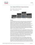
SYSTEM OVERVIEW
Preface:
Description:
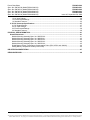
This document provides power data and system application information for the following
equipment used in a NETSURE™ Power System.
MODEL
SPEC. NO.
PSS24/1000-23
588705100
PSS24/1000-23
PSS24/2000-23
PSS24/3000-23
PSS24/4000-23
R24-2500
C24/48-1500
588705101
588705102
588705103
588705104
1R242500
1C24481500
DESCRIPTION
8-Position Field-Expansion
Module Mounting Assembly
8-Position Module Mounting Assembly
16-Position Module Mounting Assembly
24-Position Module Mounting Assembly
32-Position Module Mounting Assembly
Rectifier Module (PCU)
DC-DC Converter Module
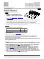
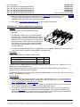
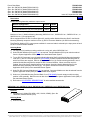
A Module Mounting Assembly and Rectifier Modules (PCUs), when used in a NETSURE
Power System equipped with a Meter-Control-Alarm (MCA) Assembly, comprise a +24V DC
Power System designed to power a load while charging a negative grounded battery. This
system is capable of operating in a batteryless installation or off battery for maintenance
purposes. The system is designed for operation with the negative output grounded.
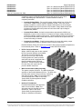
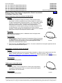
The NETSURE Power System utilizing this equipment is a
complete integrated power system containing rectifiers
(PCUs), converters, intelligent control, metering,
monitoring, and distribution. A NETSURE Power
System, utilizing this equipment, typically
consists of...
•
Module Mounting Assembly
The system contains one or more
Module Mounting Assembly(s), which
houses Rectifier Modules (PCUs) and optional
DC-DC Converter Modules. The Module Mounting
Assembly consists of one (1) to four (4) 8-position
factory assembled Module Mounting Shelf(s).
•
588705101
List 1
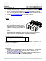
Rectifier Modules (PCUs)
The system contains Rectifier
Modules (PCUs), which provide load
power, battery float current, and
battery recharge current during
normal operating conditions. The
Rectifier Modules (PCUs) are a
constant power design. This means
that, within the normal operating ambient
temperature range, the maximum output power
available is a constant 2500W. Within this ambient
588705102
List 1
Page 1 of 48
This document is property of Emerson Network Power, Energy Systems, North America, Inc. and contains confidential and proprietary information owned by Emerson Network Power, Energy
Systems, North America, Inc. Any copying, use, or disclosure of it without the written permission of Emerson Network Power, Energy Systems, North America, Inc. is strictly prohibited.
PD588705100
PD588705101
PD588705102
PD588705103
PD588705104
Issue AC, September 28, 2009
Power Data Sheet
Spec. No. 588705100 (Model PSS24/1000-23)
Spec. No. 588705101 (Model PSS24/1000-23)
Spec. No. 588705102 (Model PSS24/2000-23)
Spec. No. 588705103 (Model PSS24/3000-23)
Spec. No. 588705104 (Model PSS24/4000-23)
temperature range, the Rectifier Modules (PCUs) will operate in one of three
modes, depending upon load demands. Transition between modes is
completely automatic.
Home
Constant Voltage Mode: For any initial output voltage setting from 23.5 to 29.0
volts, output voltage remains constant regardless of load. This is the normal
operating condition, in which loads are supplied and batteries are float charged.
Rectifier Modules (PCUs) will operate in the Constant Voltage Mode unless load
increases to the point where the product of load current and output voltage is
approximately 2500W.
Constant Power Mode: As load increases above approximately 2500W (nonadjustable), output current continues to increase, but output voltage decreases as
required to maintain constant output power. Rectifier Modules (PCUs) will operate in
the Constant Power Mode unless load continues to increase to the point where the
current limit setting is reached.
Constant Current Mode: If load increases above the current limit setting, output
voltage decreases linearly to maintain output current at current limit.
Rectifier Modules (PCUs) will continue to operate in above-normal ambient temperatures,
but at reduced power. Refer to Paragraph 1.1.6 under SPECIFICATIONS.
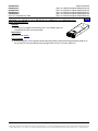
•
DC-DC Converter Modules
Where –48VDC load power is also required,
DC-DC Converter Modules are available.
The DC-DC Converter Modules can
plug into up to four (4) of the module
mounting positions in each 8-position
shelf (when the shelf is equipped with a
factory installed optional Converter
Option Kit). These converters operate
from the main +24V system bus to
provide -48VDC load power.
•
Meter-Control-Alarm (MCA) Assembly
The system contains one MCA. The MCA controls the
operation of the Rectifier Modules (PCUs). The MCA also
provides power system control, metering, monitoring,
and alarm functions. Note: This document does
not describe the MCA. Refer to the Power
System SAG (System Application Guide)
for MCA information.
•
588705103
List 1
NETSURE™ Distribution
Provides DC distribution through fuses
and/or circuit breakers. Note: This
document does not describe NETSURE
Distribution. Refer to the Power
System SAG (System Application
Guide) for distribution information.
588705104
List 1
Page 2 of 48
This document is property of Emerson Network Power, Energy Systems, North America, Inc. and contains confidential and proprietary information owned by Emerson Network Power, Energy
Systems, North America, Inc. Any copying, use, or disclosure of it without the written permission of Emerson Network Power, Energy Systems, North America, Inc. is strictly prohibited.
Power Data Sheet
Spec. No. 588705100 (Model PSS24/1000-23)
Spec. No. 588705101 (Model PSS24/1000-23)
Spec. No. 588705102 (Model PSS24/2000-23)
Spec. No. 588705103 (Model PSS24/3000-23)
Spec. No. 588705104 (Model PSS24/4000-23)
PD588705100
PD588705101
PD588705102
PD588705103
PD588705104
Issue AC, September 28, 2009
Home
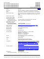
Family:
NETSURE™
Spec. Nos.:
588705100, 588705101, 588705102, 588705103, 588705104
Model:
PSS24/1000-23, PSS24/2000-23, PSS24/3000-23, PSS24/4000-23
Rectifier Input Voltage
Nominal 208-240 volts AC, single phase, 50/60 Hz, with an operating
range of 180 to 264 volts. Acceptable input frequency range is 47 to
65 Hz.
Rectifier Output Voltage:
+24 Volts DC
Converter Output Voltage:
-48 Volts DC
Rectifier Output Capacity:
Rectifier Module (PCU):
Module Mounting Assembly:
Optional DC-DC Converter
Module Output Capacity:
DC-DC Converter Module:
Module Mounting Assembly:
Agency Approval:
87.7A @ +28.5VDC to 104.2A @ +24.0VDC, 2500 Watts
Varies - see individual List Descriptions
31 Amperes (1500W)
Varies - see individual List Descriptions
UL 60950 Recognized; CAN/CSA 22.2, No. 60950-00, NEBS
Framework Type:
For Mounting in a 23-Inch Wide Relay Rack
Mounting Width:
23 Inch (Relay Rack Mounting)
Mounting Depth:
22.34 Inches
Front Projection:
6.23 Inches, fixed
Mounting Height:
588705100 and 588705101: 3-1/2 Inches (2RU)
588705102: 7 Inches (4RU)
588705103: 10-1/2 Inches (6RU)
588705104: 14 Inches (8RU)
Access:
Front and Rear for Installation and Maintenance,
Front for Operation
Control:
Microprocessor
Color:
Bright Zinc Plating (Spec. M500-53) Body,
Textured Gray (Spec. M500-147) Faceplates
List Options:
8-Position Field-Expansion Module Mounting Assembly, 8-Position
Module Mounting Assembly, 16-Position Module Mounting
Assembly, 24-Position Module Mounting Assembly, 32-Position
Module Mounting Assembly, Rectifier Modules (PCUs), DC-DC
Converter Modules
Accessory Options:
Module Mounting Position Blank Cover Panel, DC-DC Converter
Option Kit, Battery Charge Temperature Compensation Probe for
Single Probe Digital Compensation, Battery Charge Temperature
Compensation Probe Concentrator for Multiple Probe Use (TXM),
Replacement Cables, Replacement Components, Wiring Notes,
Wiring Illustrations
Environment:
Module Mounting Assembly:
-40°C to +40°C (-40°F to +104°F)
Page 3 of 48
This document is property of Emerson Network Power, Energy Systems, North America, Inc. and contains confidential and proprietary information owned by Emerson Network Power, Energy
Systems, North America, Inc. Any copying, use, or disclosure of it without the written permission of Emerson Network Power, Energy Systems, North America, Inc. is strictly prohibited.
PD588705100
PD588705101
PD588705102
PD588705103
PD588705104
Issue AC, September 28, 2009
Rectifier Module (PCU):
Converter Module:
Power Data Sheet
Spec. No. 588705100 (Model PSS24/1000-23)
Spec. No. 588705101 (Model PSS24/1000-23)
Spec. No. 588705102 (Model PSS24/2000-23)
Spec. No. 588705103 (Model PSS24/3000-23)
Spec. No. 588705104 (Model PSS24/4000-23)
-40°C to +75°C (-40°F to +167°F).
Refer also to Paragraph 1.1.6.
-40°C to +80°C (-40°F to +176°F)
Home
Page 4 of 48
This document is property of Emerson Network Power, Energy Systems, North America, Inc. and contains confidential and proprietary information owned by Emerson Network Power, Energy
Systems, North America, Inc. Any copying, use, or disclosure of it without the written permission of Emerson Network Power, Energy Systems, North America, Inc. is strictly prohibited.
Power Data Sheet
Spec. No. 588705100 (Model PSS24/1000-23)
Spec. No. 588705101 (Model PSS24/1000-23)
Spec. No. 588705102 (Model PSS24/2000-23)
Spec. No. 588705103 (Model PSS24/3000-23)
Spec. No. 588705104 (Model PSS24/4000-23)
PD588705100
PD588705101
PD588705102
PD588705103
PD588705104
Issue AC, September 28, 2009
Home
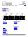
588705100, 588705101, 588705102, 588705103, 588705104
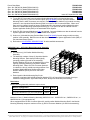
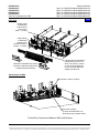
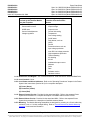
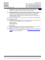
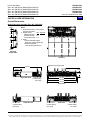
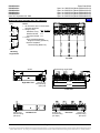
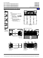
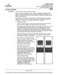
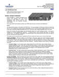
Module Mounting Assembly
588705100, List 1 (8-position, expansion)
588705101, List 1 (8-position, shown)
588705102, List 1 (16-position)
588705103, List 1 (24-position)
588705104, List 1 (32-position)
Rectifier Module (PCU)
588705100, List 2
588705101, List 2
588705102, List 2
588705103, List 2
588705104, List 2
Optional DC-DC Converter Module
(requires Converter Option Kit)
588705100, List 4
588705101, List 4
588705102, List 4
588705103, List 4
588705104, List 4
OR
See Also
System Overview
Table of Contents
Ordering Information
List Descriptions
Accessory Descriptions
Specifications
Physical Size Information
Related Documentation
Rectifier Module (PCU)
588705100, List 2
588705101, List 2
588705102, List 2
588705103, List 2
588705104, List 2
Page 5 of 48
This document is property of Emerson Network Power, Energy Systems, North America, Inc. and contains confidential and proprietary information owned by Emerson Network Power, Energy
Systems, North America, Inc. Any copying, use, or disclosure of it without the written permission of Emerson Network Power, Energy Systems, North America, Inc. is strictly prohibited.
PD588705100
PD588705101
PD588705102
PD588705103
PD588705104
Issue AC, September 28, 2009
Power Data Sheet
Spec. No. 588705100 (Model PSS24/1000-23)
Spec. No. 588705101 (Model PSS24/1000-23)
Spec. No. 588705102 (Model PSS24/2000-23)
Spec. No. 588705103 (Model PSS24/3000-23)
Spec. No. 588705104 (Model PSS24/4000-23)
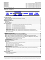
TABLE OF CONTENTS
Ordering Information
System
Overview
Picture
List
Descriptions
Accessory
Descriptions
Specifications
Physical Size
Information
Related
Documentation
SYSTEM OVERVIEW.................................................................................................................................................1
588705100, 588705101, 588705102, 588705103, 588705104 ............................................................................5
TABLE OF CONTENTS.............................................................................................................................................6
ORDERING INFORMATION......................................................................................................................................8
List Options..........................................................................................................................................................8
Accessory Options..............................................................................................................................................9
LIST DESCRIPTIONS ..............................................................................................................................................10
588705100 List 1: Field Expansion Kit (8-Position Module Mounting Assembly).........................................10
588705101 List 1: 8-Position Module Mounting Assembly ...........................................................................11
588705102 List 1: 16-Position Module Mounting Assembly .........................................................................12
588705103 List 1: 24-Position Module Mounting Assembly .........................................................................13
588705104 List 1: 32-Position Module Mounting Assembly .........................................................................14
588705100 List 2, 588705101 List 2, 588705102 List 2, 588705103 List 2, 588705104 List 2:
Rectifier Module (PCU) ..................................................................................................................................15
588705100 List 4, 588705101 List 4, 588705102 List 4, 588705103 List 4, 588705104 List 4: DCDC Converter Module ....................................................................................................................................16
ACCESSORY DESCRIPTIONS...............................................................................................................................17
Module Mounting Position Blank Cover Panel (P/N 540959) ........................................................................17
DC-DC Converter Option Interface Component Kit (P/N 540806).................................................................17
Battery Charge Temperature Compensation Probe for Single Probe Digital Compensation ...................18
Battery Charge Temperature Compensation Probe Concentrator for Multiple Probe Use (TXM) ............19
Battery Temperature Probe Concentrator Kit (P/N 524570)..........................................................................19
Analog Battery Temperature Probe (P/N 521262).........................................................................................19
TXM Extension Cable (P/N 514153) ..............................................................................................................19
Replacement Cables .........................................................................................................................................20
Replacement Components ...............................................................................................................................20
Wiring Notes ......................................................................................................................................................21
AC Input Branch Circuit Protection and Wire Size Selection.........................................................................21
Shelf Frame Ground Wire Size Selection ......................................................................................................22
DC Output Connections: +24VDC System Output .......................................................................................22
DC Output Connections: –48VDC Subsystem Output..................................................................................22
External Alarms Wire Size Selection..............................................................................................................22
Wiring Illustrations ............................................................................................................................................23
AC Input and Frame Ground (for each 8-Position Module Mounting Shelf in the Module Mounting
Assembly).......................................................................................................................................................23
DC Output ......................................................................................................................................................24
Alarm/Control to MCA ....................................................................................................................................24
SPECIFICATIONS....................................................................................................................................................25
1. Rectifier (PCU) Specifications .....................................................................................................................25
1.1 DC Output Ratings ...................................................................................................................................25
Page 6 of 48
This document is property of Emerson Network Power, Energy Systems, North America, Inc. and contains confidential and proprietary information owned by Emerson Network Power, Energy
Systems, North America, Inc. Any copying, use, or disclosure of it without the written permission of Emerson Network Power, Energy Systems, North America, Inc. is strictly prohibited.
Power Data Sheet
Spec. No. 588705100 (Model PSS24/1000-23)
Spec. No. 588705101 (Model PSS24/1000-23)
Spec. No. 588705102 (Model PSS24/2000-23)
Spec. No. 588705103 (Model PSS24/3000-23)
Spec. No. 588705104 (Model PSS24/4000-23)
PD588705100
PD588705101
PD588705102
PD588705103
PD588705104
Issue AC, September 28, 2009
1.2 AC Input Ratings ......................................................................................................................................28
1.3 Environmental Ratings .............................................................................................................................30
1.4 Standard Features....................................................................................................................................32
2. DC-DC Converter Specifications.................................................................................................................37
2.1 DC Output Ratings ...................................................................................................................................37
2.2 DC Input Ratings ......................................................................................................................................37
2.3 Environmental Ratings .............................................................................................................................38
2.4 Standard Features....................................................................................................................................39
PHYSICAL SIZE INFORMATION ............................................................................................................................41
Overall Dimensions ...........................................................................................................................................41
Module Mounting Assembly Spec. No. 588705100 .......................................................................................41
Module Mounting Assembly Spec. No. 588705101 .......................................................................................42
Module Mounting Assembly Spec. No. 588705102 .......................................................................................43
Module Mounting Assembly Spec. No. 588705103 .......................................................................................44
Module Mounting Assembly Spec. No. 588705104 .......................................................................................45
Digital Battery Charge Temperature Compensation Probe (P/N 107021 and 106824).................................46
Analog Battery Temperature Probe (P/N 521262).........................................................................................46
RELATED DOCUMENTATION................................................................................................................................47
REVISION RECORD ................................................................................................................................................48
Page 7 of 48
This document is property of Emerson Network Power, Energy Systems, North America, Inc. and contains confidential and proprietary information owned by Emerson Network Power, Energy
Systems, North America, Inc. Any copying, use, or disclosure of it without the written permission of Emerson Network Power, Energy Systems, North America, Inc. is strictly prohibited.
PD588705100
PD588705101
PD588705102
PD588705103
PD588705104
Issue AC, September 28, 2009
Power Data Sheet
Spec. No. 588705100 (Model PSS24/1000-23)
Spec. No. 588705101 (Model PSS24/1000-23)
Spec. No. 588705102 (Model PSS24/2000-23)
Spec. No. 588705103 (Model PSS24/3000-23)
Spec. No. 588705104 (Model PSS24/4000-23)
Home
ORDERING INFORMATION
List Options
This equipment is used in a NETSURE Power System. Refer also to the Power System's documentation.
Order the following by the items Part Number as specified in the following table.
When viewing electronically, click on the List # to jump to the detailed description page.
List
#
Part Number
1
58870510001
1
1
1
1
58870510101
58870510201
58870510301
58870510401
58870510002
58870510102
58870510202
58870510302
58870510402
58870510004
58870510104
58870510204
58870510304
58870510404
2
4
Description
Field Expansion Kit. Provides one (1) 8-Position Module
Mounting Assembly and components required for field
installation in a Power System.
One (1) 8-Position Module Mounting Assembly.
One (1) 16-Position Module Mounting Assembly.
One (1) 24-Position Module Mounting Assembly.
One (1) 32-Position Module Mounting Assembly.
Mounting
Positions
(1U = 1-3/4”)
2RU
2RU
4RU
6RU
8RU
Rectifier Module (PCU).
--
DC-DC Converter Module.
--
Page 8 of 48
This document is property of Emerson Network Power, Energy Systems, North America, Inc. and contains confidential and proprietary information owned by Emerson Network Power, Energy
Systems, North America, Inc. Any copying, use, or disclosure of it without the written permission of Emerson Network Power, Energy Systems, North America, Inc. is strictly prohibited.
Power Data Sheet
Spec. No. 588705100 (Model PSS24/1000-23)
Spec. No. 588705101 (Model PSS24/1000-23)
Spec. No. 588705102 (Model PSS24/2000-23)
Spec. No. 588705103 (Model PSS24/3000-23)
Spec. No. 588705104 (Model PSS24/4000-23)
PD588705100
PD588705101
PD588705102
PD588705103
PD588705104
Issue AC, September 28, 2009
Home
Accessory Options
Order the following by the items Part Number as specified in the ACCESSORY DESCRIPTIONS section.
When viewing electronically, click on the link to jump to the detailed description page.
Description
Part Number
Module Mounting Position Blank Cover Panel
DC-DC Converter Option Kit
Battery Charge Temperature Compensation
Probe for Single Probe Digital Compensation
Battery Charge Temperature Compensation
Probe Concentrator for Multiple Probe Use (TXM)
See ACCESSORY
DESCRIPTIONS
Section
Replacement Cables
Replacement Components
Wiring Notes
Wiring Illustrations
Page 9 of 48
This document is property of Emerson Network Power, Energy Systems, North America, Inc. and contains confidential and proprietary information owned by Emerson Network Power, Energy
Systems, North America, Inc. Any copying, use, or disclosure of it without the written permission of Emerson Network Power, Energy Systems, North America, Inc. is strictly prohibited.
PD588705100
PD588705101
PD588705102
PD588705103
PD588705104
Issue AC, September 28, 2009
Power Data Sheet
Spec. No. 588705100 (Model PSS24/1000-23)
Spec. No. 588705101 (Model PSS24/1000-23)
Spec. No. 588705102 (Model PSS24/2000-23)
Spec. No. 588705103 (Model PSS24/3000-23)
Spec. No. 588705104 (Model PSS24/4000-23)
Home
LIST DESCRIPTIONS
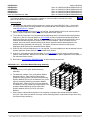
588705100 List 1: Field Expansion Kit
(8-Position Module Mounting Assembly)
Features
♦
Provides one (1) 8-Position Module Mounting
Assembly, and components required for field
installation in an existing NETSURE Power System.
♦
Expands capacity of a NETSURE Power System
equipped with a 588705101 List 1, 588705102 List 1,
or 588705103 List 1.
♦
The assembly consists of one (1) 8-position Module Mounting Shelf. The shelf provides eight (8) module
mounting positions (8 total for the assembly). Rectifier Modules (PCUs) can be installed in any of the
eight (8) mounting positions. When a DC-DC Converter Option Kit is ordered, the four (4) middle
mounting positions will accept either Rectifier Modules (PCUs) or DC-DC Converter Modules.
♦
The 8-position Module Mounting Shelf is equipped with individual Rectifier Module (PCU) AC input feeds
(one branch circuit per module mounting position, eight feeds total).
Restrictions
Module Mounting Assembly maximum output current:
Module Configuration
(8) List 2 Rectifiers
(4) List 2 Rectifiers & (4) List 4 Converters
+24VDC
-48VDC
800A
400A
0A
125A
For field installation only.
Cannot be used with a Spec No. 588705104 List 1 Assembly.
Maximum of one (1) Module Mounting Expansion Assembly (588705100 List 1) per equipment bay.
When equipped with a DC-DC Converter Option Kit, the 8-position Module Mounting Shelf accepts a
maximum of four (4) DC-DC Converter Modules.
Total Rectifier Module (PCU) output power available for customer loads is reduced by the input power of each
DC-DC Converter Module installed.
Ordering Notes
1) Order one (1) 588705100 List 1 per power system bay as required (see Restrictions above). Can also be
ordered from the System Application Guide (SAG) of the associated Power System.
2) Order Rectifier Modules (PCUs) per List 2 as required. Rectifier Modules (PCUs) can also be ordered
from the System Application Guide (SAG) of the associated Power System.
3) To use DC-DC Converters in the 8-position Module Mounting Shelf, order one (1) DC-DC Converter
Option Kit (P/N 540806) for the 8-position Module Mounting Shelf. The kit allows the middle four (4)
module mounting positions to accept DC-DC Converter Modules or Rectifier Modules (PCUs). This
option can also be ordered from the System Application Guide (SAG) of the associated Power System.
4) Order DC-DC Converter Modules per List 4 as required. Converter Modules can also be ordered from the
System Application Guide (SAG) of the associated Power System.
Page 10 of 48
This document is property of Emerson Network Power, Energy Systems, North America, Inc. and contains confidential and proprietary information owned by Emerson Network Power, Energy
Systems, North America, Inc. Any copying, use, or disclosure of it without the written permission of Emerson Network Power, Energy Systems, North America, Inc. is strictly prohibited.
Power Data Sheet
Spec. No. 588705100 (Model PSS24/1000-23)
Spec. No. 588705101 (Model PSS24/1000-23)
Spec. No. 588705102 (Model PSS24/2000-23)
Spec. No. 588705103 (Model PSS24/3000-23)
Spec. No. 588705104 (Model PSS24/4000-23)
PD588705100
PD588705101
PD588705102
PD588705103
PD588705104
Issue AC, September 28, 2009
5) Order one (1) Module Mounting Position Blank Cover (P/N 540959) for each empty module
mounting position in the assembly. Blank Covers can also be ordered from the System
Application Guide (SAG) of the associated Power System.
Home
6) Refer also to “ACCESSORY DESCRIPTIONS” for other available accessories.
588705101 List 1: 8-Position Module Mounting Assembly
Features
♦
Provides one (1) 8-Position Module Mounting
Assembly.
♦
The assembly consists of one (1) 8-position Module
Mounting Shelf. The shelf provides eight (8) module
mounting positions (8 total for the assembly). Rectifier
Modules (PCUs) can be installed in any of the eight (8)
mounting positions. When a DC-DC Converter Option
Kit is ordered, the four (4) middle mounting positions
accepts either Rectifier Modules (PCUs) or DC-DC
Converter Modules.
♦
The 8-position Module Mounting Shelf is equipped with individual Rectifier Module (PCU) AC input feeds
(one branch circuit per module mounting position, eight feeds total).
Restrictions
Module Mounting Assembly maximum output current:
Module Configuration
(8) List 2 Rectifiers
(4) List 2 Rectifiers & (4) List 4 Converters
+24VDC
-48VDC
800A
400A
0A
125A
Maximum of one (1) Module Mounting Assembly (588705101 List 1, 588705102 List 1, 588705103 List 1, or
588705104 List 1) per equipment bay.
When equipped with a DC-DC Converter Option Kit, the 8-position Module Mounting Shelf accepts a
maximum of four (4) DC-DC Converter Modules.
Total Rectifier Module (PCU) output power available for customer loads is reduced by the input power of each
DC-DC Converter Module installed.
Ordering Notes
1) For eight (8) module mounting positions in a relay rack, order 588705101 List 1. If more than eight (8)
module mounting positions are required, do not order multiples of 588705101 List 1; order 588705102
List 1, 588705103 List 1, or 588705104 List 1 instead.
2) Order Rectifier Modules (PCUs) per List 2 as required. Rectifier Modules (PCUs) can also be ordered
from the System Application Guide (SAG) of the associated Power System.
3) To use DC-DC Converters in the 8-position Module Mounting Shelf, order one (1) DC-DC Converter
Option Kit (P/N 540806) for the 8-position Module Mounting Shelf. The kit allows the middle four (4)
module mounting positions to accept DC-DC Converter Modules. This option can also be ordered from
the System Application Guide (SAG) of the associated Power System.
Page 11 of 48
This document is property of Emerson Network Power, Energy Systems, North America, Inc. and contains confidential and proprietary information owned by Emerson Network Power, Energy
Systems, North America, Inc. Any copying, use, or disclosure of it without the written permission of Emerson Network Power, Energy Systems, North America, Inc. is strictly prohibited.
PD588705100
PD588705101
PD588705102
PD588705103
PD588705104
Issue AC, September 28, 2009
Power Data Sheet
Spec. No. 588705100 (Model PSS24/1000-23)
Spec. No. 588705101 (Model PSS24/1000-23)
Spec. No. 588705102 (Model PSS24/2000-23)
Spec. No. 588705103 (Model PSS24/3000-23)
Spec. No. 588705104 (Model PSS24/4000-23)
4) Order DC-DC Converter Modules per List 4 as required. Converter Modules can also be ordered
from the System Application Guide (SAG) of the associated Power System.
Home
5) Order one (1) Module Mounting Position Blank Cover (P/N 540959) for each empty module mounting
position in the assembly. Blank Covers can also be ordered from the System Application Guide (SAG) of
the associated Power System.
6) Refer also to “ACCESSORY DESCRIPTIONS” for other available accessories.
588705102 List 1: 16-Position Module Mounting Assembly
Features
♦
Provides one (1) 16-Position Module Mounting
Assembly.
♦
The assembly consists of two (2) 8-position Module
Mounting Shelves. Each shelf provides eight (8)
module mounting positions (16 total for the assembly).
Rectifier Modules (PCUs) can be installed in any of the
eight (8) mounting positions per 8-position Module
Mounting Shelf. When a DC-DC Converter Option Kit
is ordered, the four (4) middle mounting positions of an
8-position Module Mounting Shelf accepts either
Rectifier Modules (PCUs) or DC-DC Converter
Modules.
♦
Each 8-position Module Mounting Shelf in the
assembly is equipped with individual Rectifier Module (PCU) AC input feeds (one branch circuit per
module mounting position, eight feeds total per shelf, sixteen feeds total per assembly).
Restrictions
Module Mounting Assembly maximum output current:
Module Configuration
(16) List 2 Rectifiers
(8) List 2 Rectifiers & (8) List 4 Converters
+24VDC
-48VDC
1600A
800A
0A
250A
Maximum of one (1) Module Mounting Assembly (588705101 List 1, 588705102 List 1, 588705103 List 1, or
588705104 List 1) per equipment bay.
When equipped with a DC-DC Converter Option Kit, each 8-position Module Mounting Shelf in the Module
Mounting Assembly accepts a maximum of four (4) DC-DC Converter Modules (8 total for the assembly).
Total Rectifier Module (PCU) output power available for customer loads is reduced by the input power of each
DC-DC Converter Module installed.
Ordering Notes
1) For sixteen (16) module mounting positions in a relay rack, order 588705102 List 1. If more than sixteen
(16) module mounting positions are required, do not order multiples of 588705102 List 1; order
588705103 List 1 or 588705104 List 1 instead.
2) Order Rectifier Modules (PCUs) per List 2 as required. Rectifier Modules (PCUs) can also be ordered
from the System Application Guide (SAG) of the associated Power System.
Page 12 of 48
This document is property of Emerson Network Power, Energy Systems, North America, Inc. and contains confidential and proprietary information owned by Emerson Network Power, Energy
Systems, North America, Inc. Any copying, use, or disclosure of it without the written permission of Emerson Network Power, Energy Systems, North America, Inc. is strictly prohibited.
Power Data Sheet
Spec. No. 588705100 (Model PSS24/1000-23)
Spec. No. 588705101 (Model PSS24/1000-23)
Spec. No. 588705102 (Model PSS24/2000-23)
Spec. No. 588705103 (Model PSS24/3000-23)
Spec. No. 588705104 (Model PSS24/4000-23)
PD588705100
PD588705101
PD588705102
PD588705103
PD588705104
Issue AC, September 28, 2009
Home
3) To use DC-DC Converters in any 8-position Module Mounting Shelf in this Module Mounting
Assembly, order one (1) DC-DC Converter Option Kit (P/N 540806) for each 8-position Module
Mounting Shelf in which Converters are required. Each kit allows the middle four (4) module mounting
positions in one 8-position Module Mounting Shelf to accept DC-DC Converter Modules. When more
than one kit is ordered, kits will be factory installed starting in the bottom 8-position Module Mounting
Shelf in the Module Mounting Assembly and working up. This option can also be ordered from the
System Application Guide (SAG) of the associated Power System.
4) Order DC-DC Converter Modules per List 4 as required. Converter Modules can also be ordered from the
System Application Guide (SAG) of the associated Power System.
5) Order one (1) Module Mounting Position Blank Cover (P/N 540959) for each empty module mounting
position in the assembly. Blank Covers can also be ordered from the System Application Guide (SAG) of
the associated Power System.
6) Refer also to “ACCESSORY DESCRIPTIONS” for other available accessories.
588705103 List 1: 24-Position Module Mounting Assembly
Features
♦
Provides one (1) 24-Position Module Mounting
Assembly.
♦
The assembly consists of three (3) 8-position Module
Mounting Shelves. Each shelf provides eight (8)
mounting positions (24 total for the assembly).
Rectifier Modules (PCUs) can be installed in any of the
eight (8) mounting positions per 8-position Module
Mounting Shelf. When a DC-DC Converter Option Kit
is ordered, the four (4) middle mounting positions of an
8-position Module Mounting Shelf accepts either
Rectifier Modules (PCUs) or DC-DC Converter
Modules.
♦
Each 8-position Module Mounting Shelf in the
assembly is equipped with individual Rectifier Module (PCU) AC input feeds (one branch circuit per
module mounting position, eight feeds total per shelf, twenty-four feeds total per assembly).
Restrictions
Module Mounting Assembly maximum output current:
Module Configuration
+24VDC
(20) List 2 Rectifiers & (4) List 4 Converters
2000A*
(12) List 2 Rectifiers & (12) List 4 Converters
1200A
* - Maximum bay rating of associated Power System
-48VDC
125A
375A
Maximum of one (1) Module Mounting Assembly (588705101 List 1, 588705102 List 1, 588705103 List 1, or
588705104 List 1) per equipment bay.
When equipped with a DC-DC Converter Option Kit, each 8-position Module Mounting Shelf in the Module
Mounting Assembly accepts a maximum of four (4) DC-DC Converter Modules (12 total for the assembly).
Page 13 of 48
This document is property of Emerson Network Power, Energy Systems, North America, Inc. and contains confidential and proprietary information owned by Emerson Network Power, Energy
Systems, North America, Inc. Any copying, use, or disclosure of it without the written permission of Emerson Network Power, Energy Systems, North America, Inc. is strictly prohibited.
PD588705100
PD588705101
PD588705102
PD588705103
PD588705104
Issue AC, September 28, 2009
Power Data Sheet
Spec. No. 588705100 (Model PSS24/1000-23)
Spec. No. 588705101 (Model PSS24/1000-23)
Spec. No. 588705102 (Model PSS24/2000-23)
Spec. No. 588705103 (Model PSS24/3000-23)
Spec. No. 588705104 (Model PSS24/4000-23)
Total Rectifier Module (PCU) output power available for customer loads is reduced by the input
power of each DC-DC Converter Module installed.
Home
Ordering Notes
1) For twenty-four (24) module mounting positions in a relay rack, order 588705103 List 1. If more than
twenty-four (24) module mounting positions are required, do not order multiples of 588705103 List 1;
order 588705104 List 1 instead.
2) Order Rectifier Modules (PCUs) per List 2 as required. Rectifier Modules (PCUs) can also be ordered
from the System Application Guide (SAG) of the associated Power System.
3) To use DC-DC Converters in any 8-position Module Mounting Shelf in this Module Mounting Assembly,
order one (1) DC-DC Converter Option Kit (P/N 540806) for each 8-position Module Mounting Shelf in
which Converters are required. Each kit allows the middle four (4) module mounting positions in one 8position Module Mounting Shelf to accept DC-DC Converter Modules. When more than one kit is
ordered, kits will be factory installed starting in the bottom 8-position Module Mounting Shelf in the
Module Mounting Assembly and working up. This option can also be ordered from the System
Application Guide (SAG) of the associated Power System.
4) Order DC-DC Converter Modules per List 4 as required. Converter Modules can also be ordered from the
System Application Guide (SAG) of the associated Power System.
5) Order one (1) Module Mounting Position Blank Cover (P/N 540959) for each empty module mounting
position in the assembly. Blank Covers can also be ordered from the System Application Guide (SAG) of
the associated Power System.
6) Refer also to “ACCESSORY DESCRIPTIONS” for other available accessories.
588705104 List 1: 32-Position Module Mounting Assembly
Features
♦
Provides one (1) 32-Position Module Mounting
Assembly.
♦
The assembly consists of four (4) 8-position Module
Mounting Shelves. Each shelf provides eight (8)
module mounting positions (32 total for the assembly).
Rectifier Modules (PCUs) can be installed in any of the
eight (8) mounting positions per 8-position Module
Mounting Shelf. When a DC-DC Converter Option Kit
is ordered, the four (4) middle mounting positions of an
8-position Module Mounting Shelf accepts either
Rectifier Modules (PCUs) or DC-DC Converter
Modules.
♦
Each 8-position Module Mounting Shelf in the assembly is equipped with individual Rectifier Module
(PCU) AC input feeds (one branch circuit per module mounting position, eight feeds total per shelf, thirtytwo feeds total per assembly).
Page 14 of 48
This document is property of Emerson Network Power, Energy Systems, North America, Inc. and contains confidential and proprietary information owned by Emerson Network Power, Energy
Systems, North America, Inc. Any copying, use, or disclosure of it without the written permission of Emerson Network Power, Energy Systems, North America, Inc. is strictly prohibited.
Power Data Sheet
Spec. No. 588705100 (Model PSS24/1000-23)
Spec. No. 588705101 (Model PSS24/1000-23)
Spec. No. 588705102 (Model PSS24/2000-23)
Spec. No. 588705103 (Model PSS24/3000-23)
Spec. No. 588705104 (Model PSS24/4000-23)
PD588705100
PD588705101
PD588705102
PD588705103
PD588705104
Issue AC, September 28, 2009
Home
Restrictions
Module Mounting Assembly maximum output current:
Module Configuration
+24VDC
(20) List 2 Rectifiers & (12) List 4 Converters 2000A*
(16) List 2 Rectifiers & (16) List 4 Converters
1600A
* - Maximum bay rating of associated Power System
-48VDC
375A
500A*
Maximum of one (1) Module Mounting Assembly (588705101 List 1, 588705102 List 1, 588705103 List 1, or
588705104 List 1) per equipment bay.
When equipped with a DC-DC Converter Option Kit, each 8-position Module Mounting Shelf in the Module
Mounting Assembly accepts a maximum of four (4) DC-DC Converter Modules (16 total for the assembly).
Total Rectifier Module (PCU) output power available for customer loads is reduced by the input power of each
DC-DC Converter Module installed.
Ordering Notes
1) For thirty-two (32) module mounting positions in a relay rack, order 588705104 List 1.
2) Order Rectifier Modules (PCUs) per List 2 as required. Rectifier Modules (PCUs) can also be ordered
from the System Application Guide (SAG) of the associated Power System.
3) To use DC-DC Converters in any 8-position Module Mounting Shelf in this Module Mounting Assembly,
order one (1) DC-DC Converter Option Kit (P/N 540806) for each 8-position Module Mounting Shelf in
which Converters are required. Each kit allows the middle four (4) module mounting positions in one 8position Module Mounting Shelf to accept DC-DC Converter Modules. When more than one kit is
ordered, kits will be factory installed starting in the bottom 8-position Module Mounting Shelf in the
Module Mounting Assembly and working up. This option can also be ordered from the System
Application Guide (SAG) of the associated Power System.
4) Order DC-DC Converter Modules per List 4 as required. Converter Modules can also be ordered from the
System Application Guide (SAG) of the associated Power System.
5) Order one (1) Module Mounting Position Blank Cover (P/N 540959) for each empty module mounting
position in the assembly. Blank Covers can also be ordered from the System Application Guide (SAG) of
the associated Power System.
6) Refer also to “ACCESSORY DESCRIPTIONS” for other available accessories.
588705100 List 2, 588705101 List 2, 588705102 List 2, 588705103 List 2, 588705104 List 2:
Rectifier Module (PCU)
Features
♦
Provides one (1) Model R24-2500 (+24V, 104.2A, 2500W), Spec. No.
1R242500, Rectifier Module (PCU).
Ordering Notes
1) Order as required.
Page 15 of 48
This document is property of Emerson Network Power, Energy Systems, North America, Inc. and contains confidential and proprietary information owned by Emerson Network Power, Energy
Systems, North America, Inc. Any copying, use, or disclosure of it without the written permission of Emerson Network Power, Energy Systems, North America, Inc. is strictly prohibited.
PD588705100
PD588705101
PD588705102
PD588705103
PD588705104
Issue AC, September 28, 2009
Power Data Sheet
Spec. No. 588705100 (Model PSS24/1000-23)
Spec. No. 588705101 (Model PSS24/1000-23)
Spec. No. 588705102 (Model PSS24/2000-23)
Spec. No. 588705103 (Model PSS24/3000-23)
Spec. No. 588705104 (Model PSS24/4000-23)
588705100 List 4, 588705101 List 4, 588705102 List 4, 588705103 List 4, 588705104 List 4:
DC-DC Converter Module
Home
Features
♦
Provides one (1) Model C24/48-1500 (-48V, 31A, 1500W), Spec. No.
1C24481500, DC-DC Converter Module.
Restrictions
Requires kit P/N 540806.
Ordering Notes
1) Order as required. Each 8-position Module Mounting Shelf in a Module Mounting Assembly holds up to
four (4) DC-DC Converter Modules when equipped with a DC-DC Converter Option Kit.
Page 16 of 48
This document is property of Emerson Network Power, Energy Systems, North America, Inc. and contains confidential and proprietary information owned by Emerson Network Power, Energy
Systems, North America, Inc. Any copying, use, or disclosure of it without the written permission of Emerson Network Power, Energy Systems, North America, Inc. is strictly prohibited.
Power Data Sheet
Spec. No. 588705100 (Model PSS24/1000-23)
Spec. No. 588705101 (Model PSS24/1000-23)
Spec. No. 588705102 (Model PSS24/2000-23)
Spec. No. 588705103 (Model PSS24/3000-23)
Spec. No. 588705104 (Model PSS24/4000-23)
PD588705100
PD588705101
PD588705102
PD588705103
PD588705104
Issue AC, September 28, 2009
Home
ACCESSORY DESCRIPTIONS
Module Mounting Position Blank Cover Panel (P/N 540959)
Features
♦
Covers one (1) unused module mounting position.
Ordering Notes
1) Order one (1) blank cover panel, P/N 540959, for each empty module
mounting position in the system. Blank Covers can also be ordered
from the System Application Guide (SAG) of the associated Power
System.
DC-DC Converter Option Interface Component Kit (P/N 540806)
Features
♦
Provides components to add DC-DC Converter capability to one (1)
8-position Module Mounting Shelf. When installed, the four middle
mounting positions in an 8-position Module Mounting Shelf accepts
DC-DC Converters or Rectifier Modules (PCUs).
♦
Includes cables for connection of converter output to a dual voltage
bus distribution panel assembly in a Distribution Cabinet of an
associated Power System.
Restrictions
MUST be factory installed only.
Total rectifier output power available for customer loads is reduced by the
input power of each DC-DC Converter Module installed.
Ordering Notes
1) Order one (1) kit, P/N 540806, for each 8-position Module Mounting
Shelf in which DC-DC Converters are required. Note that some
Module Mounting Assemblies consist of multiple 8-position Module Mounting Shelves. The kit permits the
middle four (4) positions in an 8-position Module Mounting Shelf to accept DC-DC Converter Modules or
Rectifier Modules (PCUs). The kit is factory installed within the 8-position Module Mounting Shelf.
Multiple kits will be installed starting with bottom 8-position Module Mounting Shelf in the Module
Mounting Assembly and working up. Kit can also be ordered from the System Application Guide (SAG) of
the associated Power System.
2) Order up to four (4) converter modules for each kit ordered.
Page 17 of 48
This document is property of Emerson Network Power, Energy Systems, North America, Inc. and contains confidential and proprietary information owned by Emerson Network Power, Energy
Systems, North America, Inc. Any copying, use, or disclosure of it without the written permission of Emerson Network Power, Energy Systems, North America, Inc. is strictly prohibited.
PD588705100
PD588705101
PD588705102
PD588705103
PD588705104
Issue AC, September 28, 2009
Power Data Sheet
Spec. No. 588705100 (Model PSS24/1000-23)
Spec. No. 588705101 (Model PSS24/1000-23)
Spec. No. 588705102 (Model PSS24/2000-23)
Spec. No. 588705103 (Model PSS24/3000-23)
Spec. No. 588705104 (Model PSS24/4000-23)
Home
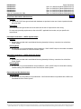
Battery Charge Temperature Compensation Probe
for Single Probe Digital Compensation
Features
♦
This system can be used with a Battery Charge Temperature Compensation Probe. This probe must be
mounted near the battery to sense battery ambient temperature. The probe connects to and allows the
MCA of the associated Power System to automatically increase or decrease the output voltage of the
system to maintain battery float current as battery ambient temperature decreases or increases,
respectively. Battery life can be extended when an optimum charge voltage to the battery with respect to
temperature is maintained. Two probes are available. Part No. 107021 has a 25-foot long cord. Part
No. 106824 has a 100 foot-long cord. See Overall Dimensions, Digital Battery Charge Temperature
Compensation Probe (P/N 107021 and 106824) under PHYSICAL SIZE INFORMATION for a
dimensional drawing.
♦
Allows Rectifier Module Battery Charge Temperature Compensation.
♦
For more features, see the SPECIFICATIONS section.
♦
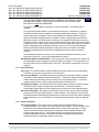
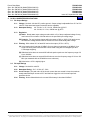
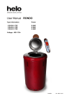
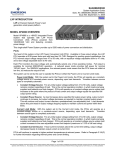
Temperature Curve: Refer to Figure 1.
Ordering Notes
1) Order one Battery Charge Temperature Compensation Probe per Power System, as required. Can also
be ordered from the System Application Guide (SAG) of the associated Power System.
Decreasing
Voltage
Increasing
MAX W/T
Adjustable from
Float to 29.25V max.*
SLOPE
Adjustable from 0.0 V / °C
to 0.1 V / °C
FLOAT
Determines Float Mode
Output Voltage at 25°C.
Adjustable from 23.5V
to 29.0V max.*
MIN W/T
Adjustable from
Float to 23V
* Maximum setting is automatically
limited to 0.5 volt less than HVSD setting.
Decreasing
Temperature
Increasing
+25°C
(+77°F)
Figure 1
Typical Float Charge Thermal Characteristics
Using Optional Battery Charge Digital Temperature Compensation Probe
(Indicated parameters are user-adjustable via the associated MCA.)
Page 18 of 48
This document is property of Emerson Network Power, Energy Systems, North America, Inc. and contains confidential and proprietary information owned by Emerson Network Power, Energy
Systems, North America, Inc. Any copying, use, or disclosure of it without the written permission of Emerson Network Power, Energy Systems, North America, Inc. is strictly prohibited.
Power Data Sheet
Spec. No. 588705100 (Model PSS24/1000-23)
Spec. No. 588705101 (Model PSS24/1000-23)
Spec. No. 588705102 (Model PSS24/2000-23)
Spec. No. 588705103 (Model PSS24/3000-23)
Spec. No. 588705104 (Model PSS24/4000-23)
PD588705100
PD588705101
PD588705102
PD588705103
PD588705104
Issue AC, September 28, 2009
Home
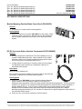
Battery Charge Temperature Compensation Probe Concentrator
for Multiple Probe Use (TXM)
Battery Temperature Probe Concentrator Kit (P/N 524570)
Features
♦
The Battery Temperature Probe Concentrator (TXM) expands battery
temperature monitoring capabilities by providing a means of monitoring up
to eight (8) analog battery temperature probes. The TXM provides a digital
output for connection to the associated Power System’s MCA’s battery
temperature probe connector. The MCA can be programmed to
compensate for the hottest probe reading, the average temperature of all
connected probes, or the probe connected to the lowest numbered
connector. The kit includes one TXM (P/N 521211) and one 25 ft. interface
cable (P/N 521228) for connecting the TXM to the MCA.
521211
Restrictions
Requires P/N 521262 analog probes. Cannot be used with digital probes
(P/Ns 106824 and 107021).
Ordering Notes
1) Order one Battery Charge Temperature Compensation Probe Concentrator
Kit (P/N 524570) per power system and up to eight (8) P/N 521262 probes,
as required. Can also be ordered from the System Application Guide
(SAG) of the associated Power System.
521228
2) Order extension cable P/N 514153 as required. Can also be ordered from the System Application Guide
(SAG) of the associated Power System.
Analog Battery Temperature Probe (P/N 521262)
Features
♦
An analog probe designed to sense internal battery temperature. Mounts on the negative terminal of the
battery; mounting hole clears 5/16” hardware. Includes 15 ft. cable with connector. See Overall
Dimensions, Analog Battery Temperature Probe (P/N 521262) under PHYSICAL SIZE INFORMATION for
a dimensional drawing.
Ordering Notes
1) See above Ordering Notes.
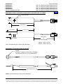
TXM Extension Cable (P/N 514153)
Features
♦
25 ft. long cable. Can be used between a P/N 521262 Analog Battery
Temperature Probe and the TXM; or to extend a P/N 521228 interface
cable between the TXM and MCA.
Ordering Notes
514153
1) See above Ordering Notes.
Page 19 of 48
This document is property of Emerson Network Power, Energy Systems, North America, Inc. and contains confidential and proprietary information owned by Emerson Network Power, Energy
Systems, North America, Inc. Any copying, use, or disclosure of it without the written permission of Emerson Network Power, Energy Systems, North America, Inc. is strictly prohibited.
PD588705100
PD588705101
PD588705102
PD588705103
PD588705104
Issue AC, September 28, 2009
Power Data Sheet
Spec. No. 588705100 (Model PSS24/1000-23)
Spec. No. 588705101 (Model PSS24/1000-23)
Spec. No. 588705102 (Model PSS24/2000-23)
Spec. No. 588705103 (Model PSS24/3000-23)
Spec. No. 588705104 (Model PSS24/4000-23)
Home
Replacement Cables
Ordering Notes
1) Refer to the System Application Guide (SAG) of the associated Power System for part numbers.
Replacement Components
Ordering Notes
1) Rectifier Module (PCU): Order via List 2 or the Power System documentation.
2) Rectifier Module Fan: Part No. 32010156 (2 required per Rectifier Module).
3) DC-DC Converter Module: Order via List 4 or the Power System documentation.
4) DC-DC Converter Module Fan: Part No. 534520 (2 required per Converter Module).
Page 20 of 48
This document is property of Emerson Network Power, Energy Systems, North America, Inc. and contains confidential and proprietary information owned by Emerson Network Power, Energy
Systems, North America, Inc. Any copying, use, or disclosure of it without the written permission of Emerson Network Power, Energy Systems, North America, Inc. is strictly prohibited.
Power Data Sheet
Spec. No. 588705100 (Model PSS24/1000-23)
Spec. No. 588705101 (Model PSS24/1000-23)
Spec. No. 588705102 (Model PSS24/2000-23)
Spec. No. 588705103 (Model PSS24/3000-23)
Spec. No. 588705104 (Model PSS24/4000-23)
PD588705100
PD588705101
PD588705102
PD588705103
PD588705104
Issue AC, September 28, 2009
Home
Wiring Notes
Refer also to the next section, Wiring Illustrations.
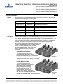
AC Input Branch Circuit Protection and Wire Size Selection
Features
♦
Each 8-position Module Mounting Shelf in a Module Mounting Assembly contains rear mounted AC input
terminal blocks and provides individual feeds to each Rectifier Module mounting position.
Restrictions
AC input terminal blocks are “tubular contact - screw compression” type and accept a wire size in the range of
10 to 24 AWG.
Ordering Notes
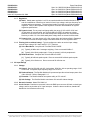
1) Refer to the following table.
THWN - 90°C Wire - Individual Feed
Four Rectifiers (8 Current and 1 Ground Wire) per Conduit
Input
Voltage
Input
Current
Overcurrent
Protection (1)
208
240
14
12
20A
15A
30°C and 40°C Ambient
Temperatures (2)
Wire
AWG (2) (3)
Conduit
Size (in.)
12
14
1/2
1/2
1
The AC input branch circuit protective device should be of the timedelay or high inrush type.
2
Wire sizes based on recommendations of the American National
Standards Institute (ANSI) approved National Fire Protection
Association's (NFPA) National Electrical Code (NEC). Table
310-16 for copper wire at 90°C conductor temperature; operating in
ambients of 30°C and 40°C was used. For other operating ambient
temperatures, refer to the National Electrical Code. For operation in
countries where the NEC is not recognized, follow applicable codes.
3
Equipment grounding conductors must be provided with the AC
input conductors supplied to the shelf. Frame ground terminals
must be connected to earth ground, not power system neutral.
Equipment grounding conductor size based on recommendations of
the NEC Table 250-122 for copper wire. If aluminum or copper clad
aluminum grounding conductor is used, refer to Table 250-122 for
increased conductor size. For operation in countries where the
NEC is not recognized, follow applicable codes.
Page 21 of 48
This document is property of Emerson Network Power, Energy Systems, North America, Inc. and contains confidential and proprietary information owned by Emerson Network Power, Energy
Systems, North America, Inc. Any copying, use, or disclosure of it without the written permission of Emerson Network Power, Energy Systems, North America, Inc. is strictly prohibited.
PD588705100
PD588705101
PD588705102
PD588705103
PD588705104
Issue AC, September 28, 2009
Power Data Sheet
Spec. No. 588705100 (Model PSS24/1000-23)
Spec. No. 588705101 (Model PSS24/1000-23)
Spec. No. 588705102 (Model PSS24/2000-23)
Spec. No. 588705103 (Model PSS24/3000-23)
Spec. No. 588705104 (Model PSS24/4000-23)
Home
Shelf Frame Ground Wire Size Selection
Features
♦
Two 10-32 X 3/4" frame ground studs with hardware are provided on the rear of each 8-position Module
Mounting Shelf.
Restrictions
Recommended frame ground wire size is the same size as the AC input branch circuit wiring.
For relay rack grounding requirements, refer to the NEC, applicable local codes, and your specific site
requirements.
DC Output Connections: +24VDC System Output
Features
♦
Busbars are provided within each Module Mounting Assembly for factory connection into a NETSURE
Power System.
Ordering Notes
1) No wire size or lug recommendations are provided here. Shelf +24VDC output is connected via busbars
to the distribution section of a NETSURE Power System.
DC Output Connections: –48VDC Subsystem Output
Features
♦
Busbars are provided within each Module Mounting Assembly for factory connection into a NETSURE
Power System.
Ordering Notes
1) No wire size or lug recommendations are provided here. Shelf –48VDC output is connected via factoryinstalled cabling to the distribution section of a NETSURE Power System.
External Alarms Wire Size Selection
Ordering Notes
1) No wire size recommendations are provided here. Shelf external alarms are provided via the MCA of an
associated NETSURE Power System.
Page 22 of 48
This document is property of Emerson Network Power, Energy Systems, North America, Inc. and contains confidential and proprietary information owned by Emerson Network Power, Energy
Systems, North America, Inc. Any copying, use, or disclosure of it without the written permission of Emerson Network Power, Energy Systems, North America, Inc. is strictly prohibited.
Power Data Sheet
Spec. No. 588705100 (Model PSS24/1000-23)
Spec. No. 588705101 (Model PSS24/1000-23)
Spec. No. 588705102 (Model PSS24/2000-23)
Spec. No. 588705103 (Model PSS24/3000-23)
Spec. No. 588705104 (Model PSS24/4000-23)
PD588705100
PD588705101
PD588705102
PD588705103
PD588705104
Issue AC, September 28, 2009
Home
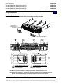
Wiring Illustrations
AC Input and Frame Ground
(for each 8-Position Module Mounting Shelf in the Module Mounting Assembly)
Holes for 3/4"
Conduit Fitting
(AC Input)
Rear View
Holes for 3/4"
Conduit Fitting
(AC Input)
Rear View
C
AC
IN
D
H
G
1
2
1
2
1
2
1
2
TB4
TB3
TB2
FRAME GROUND CONNECTION
ONE 10-32 X 3/4" STUD
AND HARDWARE
TB1
1
2
1
2
1
2
1
2
B
A
E
AC
IN
F
FRAME GROUND CONNECTION
ONE 10-32 X 3/4" STUD
AND HARDWARE
Note: Module mounting positions are lettered left to right as viewed from front of shelf,
A-D in top row and E-H in bottom row.
Note: If mounting positions B, C, F, and G are intended for DC-DC Converter installation (Converter
Option must be installed), AC input connections to these positions are not required.
Page 23 of 48
This document is property of Emerson Network Power, Energy Systems, North America, Inc. and contains confidential and proprietary information owned by Emerson Network Power, Energy
Systems, North America, Inc. Any copying, use, or disclosure of it without the written permission of Emerson Network Power, Energy Systems, North America, Inc. is strictly prohibited.
PD588705100
PD588705101
PD588705102
PD588705103
PD588705104
Issue AC, September 28, 2009
Power Data Sheet
Spec. No. 588705100 (Model PSS24/1000-23)
Spec. No. 588705101 (Model PSS24/1000-23)
Spec. No. 588705102 (Model PSS24/2000-23)
Spec. No. 588705103 (Model PSS24/3000-23)
Spec. No. 588705104 (Model PSS24/4000-23)
Home
DC Output
+24VDC Output
to Distribution
Cabinet Above
(1/4-20 x 3/4"
studs, 1" centers)
Output Return
to Distribution
Cabinet Above
(clearance holes for
1/4 bolts, 1" centers)
–48VDC Output to Distribution
Cabinet above (1/4-20 x 3/4"
studs, 5/8" centers). Present
on each shelf equipped with
DC-DC Converter Option Kit.
Cabling included in kit.
588705100 and 588705101 Shelf or
Top Shelf in 588705102, 588705103,
or 588705104 Shelf Assembly
Alarm/Control to MCA
Connector Location (to MCA)
Connector Location
(to shelf mounted below or to
termination plug in bottom shelf)
Control Bus Connections Between MCA and Shelves
Page 24 of 48
This document is property of Emerson Network Power, Energy Systems, North America, Inc. and contains confidential and proprietary information owned by Emerson Network Power, Energy
Systems, North America, Inc. Any copying, use, or disclosure of it without the written permission of Emerson Network Power, Energy Systems, North America, Inc. is strictly prohibited.
Power Data Sheet
Spec. No. 588705100 (Model PSS24/1000-23)
Spec. No. 588705101 (Model PSS24/1000-23)
Spec. No. 588705102 (Model PSS24/2000-23)
Spec. No. 588705103 (Model PSS24/3000-23)
Spec. No. 588705104 (Model PSS24/4000-23)
PD588705100
PD588705101
PD588705102
PD588705103
PD588705104
Issue AC, September 28, 2009
Home
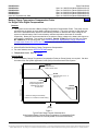
SPECIFICATIONS
Note: All MCA references pertain to the Meter-Control-Alarm assembly located in the associated Power
System. Refer to the separate System Application Guide (SAG) of the associated Power System for
the following:
•
•
•
•
MCA specifications and factory default settings.
All external alarms.
All external controls.
Local status and alarm indicators other than those provided on
the Rectifier Modules (PCUs) and DC-DC Converter Modules.
1. RECTIFIER (PCU) SPECIFICATIONS
1.1
DC Output Ratings
1.1.1
Voltage: Nominal +24 volts DC, Negative Ground.
(A) Without Battery Charge Temperature Compensation: Float voltage is adjustable from
23.50 to 28.50 volts DC. Test/equalize voltage is adjustable from 23.00 to 28.50 volts DC.
The output voltage temperature coefficient does not exceed 0.01% per degree centigrade
from -40°C to +65°C. Adjustment is made via the associated MCA. Refer to the separate
Power System documentation for the factory setting.
(B) With Battery Charge Digital Temperature Compensation Probe or TXM (multiple probe
concentrator module): With an optional battery charge digital temperature compensation
probe or TXM installed, the MCA automatically increases or decreases the output voltage as
battery ambient temperature decreases or increases, respectively. The float and
test/equalize voltage range is the same as without battery charge temperature
compensation. Refer to the separate Power System documentation for the factory setting.
Using battery and equipment manufacturers’ recommendations, the user selects the
following temperature compensation curve parameters via the MCA. Refer to the
Temperature Compensation Probe Curve (Figure 1) under ACCESSORY DESCRIPTIONS.
(1) The temperature compensation slope in volts/°C. Adjustable from zero to 100
millivolts/°C. Adjustment is made via the associated MCA. Refer to the separate
Power System documentation for the factory setting.
(2) The maximum voltage limit in volts DC. Adjustable from float up to 28.5 volts DC, but
automatically limited to 0.5 volt below the High Voltage Shutdown setting. Adjustment
is made via the associated MCA. Refer to the separate Power System documentation
for the factory setting.
(3) The minimum voltage limit in volts DC. Adjustable from float down to 24.00 volts DC,
but automatically limited to 0.5 volt above the Low Voltage Disconnect Reconnect
setting. Adjustment is made via the associated MCA. Refer to the separate Power
System documentation for the factory setting.
1.1.2
Current (One Rectifier Module [PCU]): 87.7 Amperes at 28.5 VDC to 104.2 Amperes at 24.0
VDC.
1.1.3
Power (One Rectifier Module [PCU]): 2500W @ Vout ≥24 VDC.
Page 25 of 48
This document is property of Emerson Network Power, Energy Systems, North America, Inc. and contains confidential and proprietary information owned by Emerson Network Power, Energy
Systems, North America, Inc. Any copying, use, or disclosure of it without the written permission of Emerson Network Power, Energy Systems, North America, Inc. is strictly prohibited.
PD588705100
PD588705101
PD588705102
PD588705103
PD588705104
Issue AC, September 28, 2009
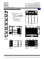
1.1.4
Power Data Sheet
Spec. No. 588705100 (Model PSS24/1000-23)
Spec. No. 588705101 (Model PSS24/1000-23)
Spec. No. 588705102 (Model PSS24/2000-23)
Spec. No. 588705103 (Model PSS24/3000-23)
Spec. No. 588705104 (Model PSS24/4000-23)
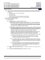
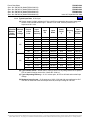
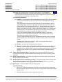
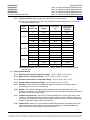
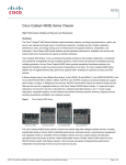
Output Characteristics: The relationship between output voltage and current is
summarized in the following table and depicted graphically in the following illustration.
Output
Power
Output
Current
Output
Voltage
2500 W
2500 W
87.7 A
104.2 A
28.5 VDC
24.0 VDC
Home
Output voltage vs. output current
max. output power 2500 W
Output voltage (V)
30
25
20
15
10
5
0
0
10
20
30
40
50
60
70
80
90
100
110
Output current (A)
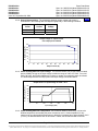
1.1.5
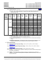
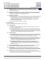
Power Derating Based on Input Voltage: The Rectifier Module can provide maximum rated
power (2500W) as long as the input voltage is within the range of 180 to 275 VAC. From 180
VAC to 90 VAC, the Rectifier Module will continue to operate, but maximum power is reduced.
The relationship between the output power and input voltage is illustrated below.
% of Max. Output Power
Output Power vs. Input Voltage at Tamb < 50 C
120
100
80
60
40
20
0
0
1.1.6
50
100
150
200
Input Voltage (VAC)
250
300
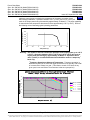
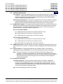
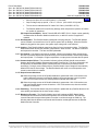
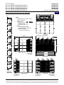
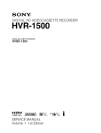
Power Derating Based on Temperature: Each Rectifier Module continuously monitors the
ambient temperature surrounding the power conversion circuit. If this temperature for any
reason (such as a high ambient temperature or failed fan) increases above approximately +50°C
(+122°F), the Rectifier Module will not shut down. Rather, the Rectifier Module will limit its
Page 26 of 48
This document is property of Emerson Network Power, Energy Systems, North America, Inc. and contains confidential and proprietary information owned by Emerson Network Power, Energy
Systems, North America, Inc. Any copying, use, or disclosure of it without the written permission of Emerson Network Power, Energy Systems, North America, Inc. is strictly prohibited.
Power Data Sheet
Spec. No. 588705100 (Model PSS24/1000-23)
Spec. No. 588705101 (Model PSS24/1000-23)
Spec. No. 588705102 (Model PSS24/2000-23)
Spec. No. 588705103 (Model PSS24/3000-23)
Spec. No. 588705104 (Model PSS24/4000-23)
PD588705100
PD588705101
PD588705102
PD588705103
PD588705104
Issue AC, September 28, 2009
Home
maximum output power to maintain the temperature of the power conversion circuit
within design parameters. Operation between +50°C (+122°F) and +65°C (149°F) will
result in the output power being decreased by approximately 33 Watts/°C. Full power capability
is restored when the temperature decreases to below approximately +50°C (+122°F). Refer to
the following curves illustrating typical operating parameters.
Output power vs. Temperature at Uin > 180 VAC
% of output power
120
100
80
60
40
20
0
-40
-20
0
20
40
60
80
100
Temperature (C)
Warning: The module is rated for continuous operation at full output power up to +50°C
(+122°F). Operation between +50°C (+122°F) and +65°C (149°F) will result in
output power decreasing by approximately 33 Watts/°C. Operation above
+65°C (+149°F) is considered abnormal and should be used on a temporary1
basis only.
1
Temporary Operation at Abnormal Temperature: Temporary operation is
defined as a period of not more than eight consecutive hours per day, and a total
of not more than 15 days in a year. (This refers to a total of 120 hours in any
given year, but no more than 15 occurrences in that one-year period.)
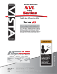
Ambient Temperature Effects on Power and Current Limit (Typical)
240Vin, Output Voltage and Current Limit Set to Maxinum
Output Voltage (V)
30
25
50°C,
55°C,
60°C,
65°C,
70°C,
20
15
10
2500W
2333W
2167W
2000W
1000W
5
0
0
20
40
60
80
100
120
Output Current (A)
Page 27 of 48
This document is property of Emerson Network Power, Energy Systems, North America, Inc. and contains confidential and proprietary information owned by Emerson Network Power, Energy
Systems, North America, Inc. Any copying, use, or disclosure of it without the written permission of Emerson Network Power, Energy Systems, North America, Inc. is strictly prohibited.
PD588705100
PD588705101
PD588705102
PD588705103
PD588705104
Issue AC, September 28, 2009
1.1.7
Power Data Sheet
Spec. No. 588705100 (Model PSS24/1000-23)
Spec. No. 588705101 (Model PSS24/1000-23)
Spec. No. 588705102 (Model PSS24/2000-23)
Spec. No. 588705103 (Model PSS24/3000-23)
Spec. No. 588705104 (Model PSS24/4000-23)
Home
Regulation:
(A) Static: Steady state regulation is ±0.5% as controlled within the Rectifier Module for any
and all combinations of load from no load to full load, input voltage, and input frequency at a
constant ambient temperature. The associated system Controller may provide increased
regulation. Refer to the separate Power System or Controller documentation for system
regulation specifications.
(B) Dynamic Load: For any step load change within the range of 10% to 90% of full load
(91.8A) within 50 microseconds, per Telcordia GR-947-CORE, the maximum voltage
transient will not exceed ±5% of the initial steady state voltage within 250 microseconds.
Recovery to within 1% of the initial steady state voltage does not exceed 4 milliseconds.
(C) Dynamic Line: Any step change of the line voltage within the limits specified in Paragraph
1.2.1 shall not cause the output voltage to deviate outside the ±0.5% regulation band.
1.1.8
Filtering (with or without battery): Typical readings were taken at nominal input voltage,
nominal output voltage, 50% load, and 25°C (77°F) ambient.
(A) Voice Band Noise: Complies with Telcordia GR-947-CORE.
(1) Typically 30 dBrn with C-message weighting. Does not exceed 32 dBrn C.
(2) Typically 0.6 millivolt psophometric. Does not exceed 1 millivolt psophometric.
(B) Wide Band Noise: Complies with Telcordia GR-947-CORE.
(1) Typically 80 millivolts peak-to-peak. Does not exceed 250 millivolts peak-to-peak.
(2) Typically 6.3 millivolts rms. Does not exceed 50 millivolts rms.
1.2
AC Input Ratings
1.2.1
Voltage:
(A) Normal: Nominal 208-240 volts AC, single phase, 50/60 Hz, with an operating range of 180
to 264 volts. Acceptable input frequency range is 47 to 65 Hz.
(B) Reduced Output: The Rectifier Module will operate and provide reduced output power from
180 to 90 volts. Refer to Paragraph 1.1.5.
(C) Extended: The Rectifier Module can operate safely to 275 volts AC.
(D) Safe Voltage: The Rectifier Module can tolerate 300 volts AC without damage.
1.2.2
Harmonic Content: Meets EN 61000-3-2.
1.2.3
Inrush Current: Peak does not exceed 2 times the RMS input current at full load, nominal input
voltage, and for any duration of AC input interrupts. Under the above conditions, standard AC
distribution circuit breakers will not trip.
Page 28 of 48
This document is property of Emerson Network Power, Energy Systems, North America, Inc. and contains confidential and proprietary information owned by Emerson Network Power, Energy
Systems, North America, Inc. Any copying, use, or disclosure of it without the written permission of Emerson Network Power, Energy Systems, North America, Inc. is strictly prohibited.
Power Data Sheet
Spec. No. 588705100 (Model PSS24/1000-23)
Spec. No. 588705101 (Model PSS24/1000-23)
Spec. No. 588705102 (Model PSS24/2000-23)
Spec. No. 588705103 (Model PSS24/3000-23)
Spec. No. 588705104 (Model PSS24/4000-23)
PD588705100
PD588705101
PD588705102
PD588705103
PD588705104
Issue AC, September 28, 2009
Home
1.2.4
Typical Input Data: 50 Hz Input
(A) System output is initially adjusted to 27.24 volts DC as measured at the system sense point
at 50% of full load and nominal input. “Percent of Full Load” refers to percent of 87.7
Amperes at 28.5 volts.
Number
of Rectifier
Modules
(PCUs)
Installed
Nominal
Input
Voltage
208
1
240
Percent
of Full
Load
Input
Current
(Amperes)
Input
VA
Input
Watts
Power
Factor
%
0
0.2797
58.2335
22.0705
37.9
25
3.373
699.7
694.102
99.2
86.18
327.34
50
6.383
1325.11
1322.46
99.8
90.42
432.24
75
9.535
1980.42
1978.44
99.9
90.85
617.36
100
12.719
2636.65
2634.01
99.9
90.57
847.69
110
13.65
2837.84
2832.16
99.8
90.38
929.30
120
13.717
2849.02
2843.32
99.8
89.69
1000.40
Heat
Efficiency
Dissipation
%
BTU/Hr
--
75.31
0
0.2962
71.1769
19.716
27.7
--
67.27
25
2.942
704.315
692.341
98.3
86.30
323.60
50
5.54
1322.95
1317.66
99.6
90.70
418.05
75
8.255
1973.77
1969.82
99.8
91.21
590.74
100
11.015
2627.08
2621.82
99.8
91.06
800.12
110
11.84
2825.02
2819.37
99.8
90.77
887.98
120
11.882
2835.05
2829.38
99.8
90.13
952.81
(B) Typical Power Factor: Greater than or equal to 99.6% for any load greater than or equal to
50% of rated full load at nominal line. Meets IEC 1000-3-2.
(C) Typical Operating Efficiency: 91.21% at best point, 90.57% at full load and nominal input
voltage.
(D) Maximum Input Current: 15.43 amperes at 100% of full load with output adjusted to 28.5
volts DC as measured at the shelf output terminals, and input voltage of 180 volts.
Page 29 of 48
This document is property of Emerson Network Power, Energy Systems, North America, Inc. and contains confidential and proprietary information owned by Emerson Network Power, Energy
Systems, North America, Inc. Any copying, use, or disclosure of it without the written permission of Emerson Network Power, Energy Systems, North America, Inc. is strictly prohibited.
PD588705100
PD588705101
PD588705102
PD588705103
PD588705104
Issue AC, September 28, 2009
Power Data Sheet
Spec. No. 588705100 (Model PSS24/1000-23)
Spec. No. 588705101 (Model PSS24/1000-23)
Spec. No. 588705102 (Model PSS24/2000-23)
Spec. No. 588705103 (Model PSS24/3000-23)
Spec. No. 588705104 (Model PSS24/4000-23)
Home
1.2.5
Typical Input Data: 60 Hz Input
(A) System output is initially adjusted to 27.24 volts DC as measured at the system sense points
at 50% of full load and nominal input. “Percent of Full Load” refers to percent of 87.7
Amperes at 28.5 volts.
Number
of Rectifier
Modules
(PCUs)
Installed
Nominal
Input
Voltage
208
1
240
Percent
of Full
Load
Input
Current
(Amperes)
Input
VA
Input
Watts
Power
Factor
%
0
0.3166
65.9478
21.1692
32.1
Heat
Efficiency
Dissipation
%
BTU/Hr
--
72.23
25
3.376
703.896
696.153
98.9
85.93
334.11
50
6.406
1330.53
1327.87
99.8
90.18
445.11
75
9.495
1973.06
1971.09
99.9
90.84
615.79
100
12.683
2639.33
2636.69
99.9
90.57
848.46
110
13.683
2839.22
2833.54
99.8
90.26
942.01
120
13.69
2846.15
2840.46
99.8
89.74
994.54
0
0.3433
82.4263
19.535
23.7
--
66.66
25
2.956
708.258
691.259
97.6
86.51
318.16
50
5.551
1327.8
1322.49
99.6
90.59
424.57
75
8.288
1975.86
1971.91
99.8
91.15
595.74
100
11.054
2625.33
2622.7
99.9
91.07
799.42
110
11.885
2819.12
2816.3
99.9
90.95
869.93
120
11.875
2827.44
2824.61
99.9
90.27
937.98
(B) Typical Power Factor: Greater than or equal to 99.6% for any load greater than or equal to
50% of rated full load at nominal line. Meets IEC 1000-3-2.
(C) Typical Operating Efficiency: 91.15% at best point, 90.57% at full load and nominal input
voltage.
(D) Maximum Input Current: 15.43 amperes at 100% of full load with output adjusted to 28.5
volts DC as measured at the shelf output terminals, and input voltage of 180 volts.
1.3
Environmental Ratings
1.3.1
Operating Ambient Temperature Range: -40°C to +75°C (-40°F to +167°F). Refer to
Paragraph 1.1.6.
1.3.2
Specification Compliant Temperature Range: -20°C to +70°C (-4°F to +158°F). Refer to
Paragraph 1.1.6.
1.3.3
Storage Ambient Temperature Range: -40°C to +85°C (-40°F to +185°F).
1.3.4
Humidity: This Rectifier Module is capable of operating in an ambient relative humidity range of
0% to 95%, non-condensing.
1.3.5
Altitude: This Rectifier Module is capable of operating in an altitude range of -200 feet to
10,000 feet. The maximum operating ambient temperature should be de-rated by 3°C per 1000
feet above 5000 feet.
Page 30 of 48
This document is property of Emerson Network Power, Energy Systems, North America, Inc. and contains confidential and proprietary information owned by Emerson Network Power, Energy
Systems, North America, Inc. Any copying, use, or disclosure of it without the written permission of Emerson Network Power, Energy Systems, North America, Inc. is strictly prohibited.
Power Data Sheet
Spec. No. 588705100 (Model PSS24/1000-23)
Spec. No. 588705101 (Model PSS24/1000-23)
Spec. No. 588705102 (Model PSS24/2000-23)
Spec. No. 588705103 (Model PSS24/3000-23)
Spec. No. 588705104 (Model PSS24/4000-23)
1.3.6
PD588705100
PD588705101
PD588705102
PD588705103
PD588705104
Issue AC, September 28, 2009
Home
Ventilation Requirements:
(A) Ventilation: The Rectifier Modules (PCUs) are fan cooled and utilize front to back forced
ventilation. A Module Mounting Assembly must be mounted so ventilating openings are not
blocked and temperature of the air entering the cabinet does not exceed the Operating
Ambient Temperature Range stated above.
(B) Stacking Considerations: This system is designed for front to back ventilation to facilitate
stacking of Module Mounting Shelves, one above the other, in a relay rack. There is no
spacing requirement between stacked Module Mounting Shelves of a single system.
1.3.7
Audible Noise (System): The audible noise at any point two feet from any vertical surface of a
Rectifier Mounting Shelf (with Rectifier Modules installed and fans operating) does not exceed
the following limits. The audible noise was measured with the fan control circuit enabled. A
Sound Level Meter conforming to ANSI S1.4 was used.
(A) For One Rectifier Module:
(1) 50dB-A maximum at less than 32°C ambient, half load or less.
(2) 60dB-A maximum at less than 32°C ambient, full load.
(3) 70dB-A maximum at greater than 32°C ambient, full load.
(B) For Eight Rectifier Modules:
(1) 61dB-A maximum at less than 32°C ambient, half load or less.
(2) 71dB-A maximum at less than 32°C ambient, full load.
(3) 81dB-A maximum at greater than 32°C ambient, full load.
1.3.8
EMI/RFI Suppression: Rectifier Modules operating in a Module Mounting Shelf conform to the
requirements of FCC rules Part 15, Subpart B, Class B for Radiated and Conducted emissions
limits.
1.3.9
Surge Protection: Compliance with EN61000-4-5 Installation Class 4, and capable of
withstanding surges per ANSI/IEEE C 62.41 1980 Category B3 across the input terminals.
Note: This level of protection is a widely used standard for telecommunications power
equipment. As with all such equipment, it is the end user's responsibility to provide an
adequately sized Surge Suppression Device at the commercial power service entrance of
the building that reduces all incoming surges to levels below the classes/categories
stated for the equipment.
1.3.10 Compliance Information:
(A) Safety Compliance: This unit meets the requirements of UL 60950-1, Standard for
Information Technology Equipment, and is UL Recognized as a power supply for use in
Telephone, Electronic Data Processing or Information Processing Equipment. This unit
meets the requirements of CAN/CSA 22.2, No. 60950-00 and is tested and Certified by UL
("c UR") as a Component Type Power Supply.
(B) The Rectifier Modules are RoHS 5/6 compliant.
Page 31 of 48
This document is property of Emerson Network Power, Energy Systems, North America, Inc. and contains confidential and proprietary information owned by Emerson Network Power, Energy
Systems, North America, Inc. Any copying, use, or disclosure of it without the written permission of Emerson Network Power, Energy Systems, North America, Inc. is strictly prohibited.
PD588705100
PD588705101
PD588705102
PD588705103
PD588705104
Issue AC, September 28, 2009
Power Data Sheet
Spec. No. 588705100 (Model PSS24/1000-23)
Spec. No. 588705101 (Model PSS24/1000-23)
Spec. No. 588705102 (Model PSS24/2000-23)
Spec. No. 588705103 (Model PSS24/3000-23)
Spec. No. 588705104 (Model PSS24/4000-23)
1.3.11 NEBS Compliance: Compliance verified by a Nationally Recognized Testing Laboratory
(NRTL) per GR-1089-CORE and GR-63-CORE. Contact Emerson Network Power for NEBS
compliance reports.
In order to remain compliant during a fan failure condition, the backup battery connection must
be utilized to provide sufficient power to the loads for up to eight (8) hours when the system is
operated at greater than 50% output power. If no backup battery connection is used, the system
must operate with a redundant module installed.
1.4
Standard Features
1.4.1
Type of Power Conversion Circuit: High frequency.
1.4.2
Float Charging Output Mode: In this mode of operation, system output voltage is constant and
output current does not exceed the current limit setting and output power does not exceed
2500W. During normal operation, the battery is not required to furnish load current and remains
in a fully charged condition.
The float voltage setting can be checked and/or adjusted without removing a Rectifier Module
(PCU) or affecting the load. One adjustment changes the output of all Rectifier Modules (PCUs).
Note: If the current demanded by the load exceeds the current limit setting of the system, the
battery is required to furnish the difference in load current and begins discharging. If the
demand by the load exceeds 2500W per rectifier (PCU), the battery is required to furnish
the difference and begins discharging.
Note: If the system is used with a digital battery charge temperature compensation probe or
TXM, the MCA automatically adjusts system output. This ensures proper voltage to the
battery as battery ambient temperature fluctuates.
1.4.3
Test/Equalize Charging Output Mode: This mode of operation is used if higher output voltage
is required for equalizing the charge on all battery cells of a conventional flooded cell battery, or
for recharging the battery following a commercial power failure.
If the installation site does not require system equalize mode of operation, the equalize feature
can be used as a test feature. System equalize voltage can be adjusted to a test voltage value.
Placing the system into the test/equalize mode causes system output voltage to increase or
decrease to this test voltage value.
The test/equalize voltage setting can be checked and/or adjusted without removing a Rectifier
Module (PCU) or affecting the load. One adjustment changes the output of all Rectifier Modules
(PCUs).
Note: If the system is used with a battery charge digital temperature compensation probe or
TXM, typical equalize mode of operation is not used.
1.4.4
Output Mode of Operation Selection: There are four methods of placing the system from the
float mode to the test/equalize mode.
(A) Method 1 (Manual Test/Equalize): A user manually places the system into the
test/equalize mode via the MCA interface. A user must manually return the system to the
float mode via the MCA interface.
(B) Method 2 (Manually Initiated Timed Test/Equalize): A user manually places the system
into the test/equalize mode via the MCA interface. The system automatically returns to the
float mode after a preset programmable time period (1-99 hours, in increments of one hour).
(C) Method 3 (Automatic Test/Equalize):
Page 32 of 48
This document is property of Emerson Network Power, Energy Systems, North America, Inc. and contains confidential and proprietary information owned by Emerson Network Power, Energy
Systems, North America, Inc. Any copying, use, or disclosure of it without the written permission of Emerson Network Power, Energy Systems, North America, Inc. is strictly prohibited.
Power Data Sheet
Spec. No. 588705100 (Model PSS24/1000-23)
Spec. No. 588705101 (Model PSS24/1000-23)
Spec. No. 588705102 (Model PSS24/2000-23)
Spec. No. 588705103 (Model PSS24/3000-23)
Spec. No. 588705104 (Model PSS24/4000-23)
PD588705100
PD588705101
PD588705102
PD588705103
PD588705104
Issue AC, September 28, 2009
THE AUTOMATIC EQUALIZE FEATURE IS INTENDED FOR USE ONLY WITH
WET CELL BATTERIES. USING THIS FEATURE WITH VALVE REGULATED
BATTERIES IS NOT RECOMMENDED.
Home
This feature can be enabled or disabled by a user via the MCA. The default state is
disabled.
The Automatic Equalize feature is a time based function that is controlled by a customer
selectable multiplier and by the Battery On Discharge (BOD) alarm setpoint. The MCA’s
default setting is for a multiplier of zero, which disables the Automatic Equalize feature.
When the Automatic Equalize feature is enabled, if system voltage drops to less than the
BOD alarm setpoint, the MCA initiates a timing cycle to measure the discharge time period.
The MCA requires at least 15 minutes of continuous BOD alarm in order to prevent nuisance
equalization cycles. When system voltage rises to above the BOD alarm setpoint, the MCA
ends the discharge timing cycle and (assuming a minimum of 15 minutes has elapsed)
places the Rectifier Modules (PCUs) into the equalize mode for a customer selectable
multiple of the discharge time period (the discharge time period includes the initial 15
minutes).
The equalize time period can be set for 0 to 15 times the discharge time period, up to a
maximum of 300 hours. A zero (0) setting disables the feature.
(D) Method 4 (External Test/Equalize): A user (or external equipment) places the system into
the test/equalize mode by applying an external signal to the system. The system returns to
the float mode when the external signal is removed. This method overrides the other three
methods.
1.4.5
Input Protection:
(A) Fusing: The Rectifier Module contains double pole/neutral fusing (non user-replaceable).
Customer is to provide AC input branch circuit protection.
(B) Low Input Voltage: The Rectifier Module shuts down and its protection indicator (yellow)
illuminates if input voltage decreases below 85VAC. The Rectifier Module automatically
restarts when the input voltage returns to within the normal operating range. A low input
voltage condition does not trip the recommended input protection device.
(C) High Input Voltage: The Rectifier Module shuts down and its protection indicator (yellow)
illuminates if input voltage increases above than 280VAC. The Rectifier Module
automatically restarts when the input voltage returns to within the normal operating range.
(D) Power Interruption: Interruption and restoration of input power does not affect the proper
operation of the controls, alarm signals, or visual indicators. On restoration of input power,
the Rectifier Module automatically restarts without manual intervention and without operating
protective devices, even if connected to a completely discharged battery string or capacitor
bank.
1.4.6
Output Protection:
(A) Current Limiting: The maximum current delivered by the Rectifier Module can be
programmed from 10% to 120% of full load rating via the controller. If communication to the
controller is lost, the Rectifier Module default value is 100% of full load rating. Full load
rating for Rectifier Modules is defined as the maximum current available over the entire
output voltage range (87.7 A). The Rectifier Module can start when connected to a
completely discharged battery or capacitor bank without operating Rectifier Module
protective devices or needing any manual intervention.
Page 33 of 48
This document is property of Emerson Network Power, Energy Systems, North America, Inc. and contains confidential and proprietary information owned by Emerson Network Power, Energy
Systems, North America, Inc. Any copying, use, or disclosure of it without the written permission of Emerson Network Power, Energy Systems, North America, Inc. is strictly prohibited.
PD588705100
PD588705101
PD588705102
PD588705103
PD588705104
Issue AC, September 28, 2009
Power Data Sheet
Spec. No. 588705100 (Model PSS24/1000-23)
Spec. No. 588705101 (Model PSS24/1000-23)
Spec. No. 588705102 (Model PSS24/2000-23)
Spec. No. 588705103 (Model PSS24/3000-23)
Spec. No. 588705104 (Model PSS24/4000-23)
Home
(B) Fusing: The Rectifier Module contains an output fuse (non user-replaceable).
Rectifier Module output power is lost and its fault indicator (red) illuminates if the
output fuse opens The Rectifier Module (PCU) can be plugged into or pulled out of a shelf
while operating, without damage or opening the fuse.
(C) High Voltage Shutdown:
(1) Internal: If output voltage exceeds an adjustable preset value and the Rectifier Module
(PCU) is delivering more than 10% of its rated current, the Rectifier Module (PCU)
shuts down.
After approximately 3 seconds, the Rectifier Module (PCU) automatically restarts. If
output voltage again exceeds the high voltage shutdown value within 5 minutes, the
Rectifier Module (PCU) shuts down and locks out. Manual restart is then required (by
turning AC power to the Rectifier Module off or by removing the Rectifier Module,
waiting 5 seconds, then turning AC power to the Rectifier Module on or re-inserting the
Rectifier Module). If the Rectifier Module (PCU) does not experience a high voltage
condition within the 5-minute time-period, the restart circuit is reset.
If two or more Rectifier Modules (PCUs) are installed in a shelf, or if the shelf is
paralleled with other Module Mounting Shelves, only the Rectifier Module (PCU)
causing the high voltage condition shuts down.
The high voltage shutdown point can be checked and/or adjusted without removing a
Rectifier Module (PCU). One adjustment changes the setting of all Rectifier Modules
(PCUs).
Adjustable from 24.00 to 29.75 volts DC. Refer to the separate Power System
documentation for the factory setting.
(2) Remote: See associated Power System documentation.
(3) Backup: If Rectifier Module (PCU) output voltage exceeds a second (non-adjustable)
value of 31.0VDC ±0.5VDC, the Rectifier Module (PCU) shuts down and locks out
regardless of load. Manual restart is then required [by turning AC power to the Rectifier
Modules (PCUs) off then on, or by removing and re-inserting the Rectifier Modules
(PCUs)].
1.4.7
Power Factor Correction Failure: If the power factor correction circuit fails and results in
over/low DC bus voltage, the Rectifier Module shuts down and its protection indicator (yellow)
illuminates.
1.4.8
DC/DC Converter Failure: If the DC/DC converter fails, the Rectifier Module shuts down and
the fault indicator (red) illuminates.
1.4.9
Rectifier Module (PCU) Load Sharing (per Bay): The Rectifier Module shares load with other
Rectifier Modules operating in parallel in one cabinet to within ±3.0A difference of average
current of Rectifier Modules at 10%~100% load (max 28 rectifiers).
1.4.10 Startup Time: The Rectifier Module has two startup modes.
(A) Normal Startup:
•
Start up time, defined as beginning at AC switch on and ending when full output power
has been reached, consists of two time intervals, the delay period and the output voltage
ramp up period.
•
During the delay period the output voltage will be zero volt.
Page 34 of 48
This document is property of Emerson Network Power, Energy Systems, North America, Inc. and contains confidential and proprietary information owned by Emerson Network Power, Energy
Systems, North America, Inc. Any copying, use, or disclosure of it without the written permission of Emerson Network Power, Energy Systems, North America, Inc. is strictly prohibited.
Power Data Sheet
Spec. No. 588705100 (Model PSS24/1000-23)
Spec. No. 588705101 (Model PSS24/1000-23)
Spec. No. 588705102 (Model PSS24/2000-23)
Spec. No. 588705103 (Model PSS24/3000-23)
Spec. No. 588705104 (Model PSS24/4000-23)
PD588705100
PD588705101
PD588705102
PD588705103
PD588705104
Issue AC, September 28, 2009
Home
•
Start up time (from AC on until full power): ≤ 5 seconds.
•
Output voltage ramp up period, t: 50 ≤ t ≤ 150 ms. (10% to 90% of full power)
•
The rise time is retained with a DC load of 0.31 Ohm (+24.0VDC & 87.7A).
•
The Rectifier Module will not suffer any damage, when subjected to repetitive AC switch
on / switch off operations.
(B) Output Current Walk-In: Meets Telcordia GR-947-CORE, R3-19. Output current gradually
increases after the Rectifier Module is switched on, or after AC service is supplied or
restored.
1.4.11 Hot Swappable: The Rectifier Module is designed to be plug-and-play. The Rectifier Module
can be inserted or removed from a live DC power system with no damage. When the Rectifier
Module is plugged into the system, the system output voltage will not be affected.
1.4.12 Cooling: Each Rectifier Module contains two fans for forced convection cooling. The Rectifier
Module shuts down and its fault indicator (red) flashes if either fan fails. Fan failure is detected
and reported to controller. The fans are field replaceable.
1.4.13 Fan Control: Fan speed is continuously variable. When input voltage is within normal range,
the built-in processor adjusts fan speed according to the Rectifier Module’s internal temperature
and output power. For example, a higher temperature or output power increases the fan speed.
1.4.14 Communication Failure: The protection indicator (yellow) will flash should communication
between the Rectifier Module and associated system Controller fail. The failure information will
be reported to the associated system Controller and the Controller will process the failure
accordingly. During a communication failure, Rectifier Module output voltage will automatically
default to the last set float voltage. The Rectifier Module will revert to normal operation once
normal communication is restored.
1.4.15 Output Current Imbalance:
(A) When the average current of all Rectifier Modules is greater than 20% of full rated current,
and the difference between local Rectifier Module current and average current is greater
than 16% of full rated current, the yellow protection indicator will illuminate.
(B) When the average current of all Rectifier Modules is greater than 10% of full rated current,
and local Rectifier Module current is less than 1.5% of full rated current, then the red fault
indicator will illuminate.
1.4.16 Paralleling: This Rectifier Module may be connected in parallel with any Rectifier Module of the
same polarity and adjusted to the same output voltage.
1.4.17 Monitoring Function: The Rectifier Module has a built-in advanced DSP (Digital Signal
Processor) that monitors and controls the operation of the Rectifier Module. The DSP also
communicates with the associated system Controller in real time through the CAN bus. The
following table lists the different commands and information exchanged between the Rectifier
Module and the Controller.
Page 35 of 48
This document is property of Emerson Network Power, Energy Systems, North America, Inc. and contains confidential and proprietary information owned by Emerson Network Power, Energy
Systems, North America, Inc. Any copying, use, or disclosure of it without the written permission of Emerson Network Power, Energy Systems, North America, Inc. is strictly prohibited.
PD588705100
PD588705101
PD588705102
PD588705103
PD588705104
Issue AC, September 28, 2009
Power Data Sheet
Spec. No. 588705100 (Model PSS24/1000-23)
Spec. No. 588705101 (Model PSS24/1000-23)
Spec. No. 588705102 (Model PSS24/2000-23)
Spec. No. 588705103 (Model PSS24/3000-23)
Spec. No. 588705104 (Model PSS24/4000-23)
Commands / signals that can be
received by the Rectifier Module
from the Controller.
Information gathered by the
Controller from the Rectifier
Module.
•
•
•
•
•
•
•
•
•
•
•
•
•
Turn on/off
Current walk-in on/off
HVSD reset
Current limit adjustment
Voltage regulation
•
•
•
•
•
•
•
•
•
•
Input voltage
Output voltage
Output current
Current limit setting
Temperature
Over voltage setting
On/off status
Fault alarms, such as:
HVSD
Fan fail
Protection alarms, such as:
Input voltage protection
Inner DC bus voltage protection
High temperature protection
Thermal derating
AC derating
AC fail
Imbalanced output current
Address
Code
Date
Software version
Hardware version
1.4.18 Dimensions and Weights: See “Overall Dimensions” under PHYSICAL SIZE INFORMATION.
1.4.19 Local Controls: None.
1.4.20 Local Status and Alarm Indicators: Refer to the "Operating Procedures" chapter in the Power
System User Instructions (Section 6013) for a complete description.
(A) Power (Green)
(B) Protection (Yellow)
(C) Alarm (Red)
1.4.21 External Control Circuits: Provided via the associated MCA. Refer to the separate Power
System documentation for a complete description of available external control circuits.
1.4.22 External Alarm Circuits: Provided via the associated MCA. Refer to the separate Power
System documentation for a description of available external alarms.
1.4.23 Mounting: The Module Mounting Assemblies are designed for mounting in a 23 inch wide relay
rack with 1 inch or 1-3/4 inch multiple drilling. Refer to "Overall Dimensions, Module Mounting
Assembly" for dimensional illustration.
Page 36 of 48
This document is property of Emerson Network Power, Energy Systems, North America, Inc. and contains confidential and proprietary information owned by Emerson Network Power, Energy
Systems, North America, Inc. Any copying, use, or disclosure of it without the written permission of Emerson Network Power, Energy Systems, North America, Inc. is strictly prohibited.
Power Data Sheet
Spec. No. 588705100 (Model PSS24/1000-23)
Spec. No. 588705101 (Model PSS24/1000-23)
Spec. No. 588705102 (Model PSS24/2000-23)
Spec. No. 588705103 (Model PSS24/3000-23)
Spec. No. 588705104 (Model PSS24/4000-23)
PD588705100
PD588705101
PD588705102
PD588705103
PD588705104
Issue AC, September 28, 2009
Home
2. DC-DC CONVERTER SPECIFICATIONS
2.1
DC Output Ratings
2.1.1
Voltage: Nominal –48 volts DC, positive ground. Output voltage is adjustable from 47.5 to 52.5
volts DC if the associated system controller has the capability.
2.1.2
Nameplate Rating:
2.1.3
Regulation
48 - 52 Vdc, 31.25 - 28.9 A, 1500W max. @ 50°C.
48 - 52 Vdc, 25 - 23 A, 1200W max. @ 65°C.
(A) Static: Steady state output voltage remains within ±1% of the pre-adjusted voltage for any
load current from no load to full load and over the specified input voltage range.
(B) Dynamic: For any load step change within the range of 20% to 100% of full rated current,
the maximum voltage transient will not exceed 5% of the initial steady state voltage.
2.1.4
Filtering: With at least 10% of rated full load on the output (-20°C to +65°C).
(A) Voice band noise is less than 32 dBrnC (for more than one converter) or 40 dBrnC (for a
single converter) when measured with a noise meter using 600 ohm bridged input and
C-message weighting.
(B) Wide band noise does not exceed 250 millivolts peak to peak over the frequency range of 0
Hz to 100 MHz.
(C) Wide band noise does not exceed 50 millivolts rms over the frequency range of 0 Hz to 100
MHz (as measured with an HP3400A true rms voltmeter).
(D) Noise below –20°C is slightly higher.
2.2
DC Input Ratings
2.2.1
Voltage: Nominal 24 volts DC.
2.2.2
Nameplate Rating: 20.5 - 30 Vdc, 87 - 59 A.
2.2.3
Inrush Current: The peak value of the inrush current does not exceed 2 times the maximum
steady-state RMS input current at 25°C and shall not trigger the unit’s internal input fault
protection device.
2.2.4
Filtering: Noise reflected back to the central office battery is less than 32 dBrnC.
Page 37 of 48
This document is property of Emerson Network Power, Energy Systems, North America, Inc. and contains confidential and proprietary information owned by Emerson Network Power, Energy
Systems, North America, Inc. Any copying, use, or disclosure of it without the written permission of Emerson Network Power, Energy Systems, North America, Inc. is strictly prohibited.
PD588705100
PD588705101
PD588705102
PD588705103
PD588705104
Issue AC, September 28, 2009
Power Data Sheet
Spec. No. 588705100 (Model PSS24/1000-23)
Spec. No. 588705101 (Model PSS24/1000-23)
Spec. No. 588705102 (Model PSS24/2000-23)
Spec. No. 588705103 (Model PSS24/3000-23)
Spec. No. 588705104 (Model PSS24/4000-23)
Home
2.2.5
Typical Input Data - When equipped with one DC-DC Converter Module.
(A) The output voltage of the DC-DC Converter Module is initially adjusted to 48 volts at 50%
load and 24 volts DC input.
Input
Voltage
Percent
of Full Load
Input Current
(Amps)
Efficiency
(%)
Typical Heat
Dissipation
(BTU/Hr)
0
25
50
75
100
0
25
50
75
0.56
19.56
39.16
59.76
83.32
0.52
17.28
34.40
52.52
-91.2
91.2
89.6
85.7
-90.4
90.8
89.3
40.13
123.34
246.93
445.33
853.74
42.58
135.85
270.43
460.19
100
72.84
85.8
847.02
0
25
50
75
100
0.48
15.04
29.64
45.28
62.24
-89.0
90.4
88.7
86.1
45.86
158.06
271.85
488.84
826.54
21 VDC
24 VDC
28 VDC
(B) Maximum Current: Input current is 83.32 amperes at full load (31.25 amperes) and 21
volts DC input.
2.3
Environmental Ratings
2.3.1
Specification Compliant Temperature Range: -20°C to +50°C (-4°F to +122°F).
2.3.2
Reduced Load Temperature Range: +50°C to +80°C (+122°F to +176°F).
2.3.3
Deviation to Noise Specs. Temperature Range: -40°C to -20°C (-40°F to -4°F).
2.3.4
Storage Ambient Temperature Range: -40°C to +85°C (-40°F to +185°F).
2.3.5
Humidity: This DC-DC Converter Module is capable of operating in an ambient relative
humidity range of 0 to 95%, non-condensing.
2.3.6
Altitude: The maximum operating ambient temperature should be derated by 10°C at an
elevation of 10,000 feet. For elevations between sea level and 10,000 feet, derate the maximum
operating ambient temperature linearly.
2.3.7
Ventilation Requirements: Each DC-DC Converter Module is fan cooled, using front to back
ventilation. The Module Mounting Assembly must be located such that ventilation openings are
not blocked and temperature of the air entering the modules is not above or below the Operating
Ambient Temperature Range stated in this document.
2.3.8
Audible Noise: With four Converter Modules installed and operating, the audible noise at any
point 5 feet from any vertical surface of the equipment shelf does not exceed 68 dBA when
measured with a sound level meter conforming to ANSI S1.4.
Page 38 of 48
This document is property of Emerson Network Power, Energy Systems, North America, Inc. and contains confidential and proprietary information owned by Emerson Network Power, Energy
Systems, North America, Inc. Any copying, use, or disclosure of it without the written permission of Emerson Network Power, Energy Systems, North America, Inc. is strictly prohibited.
Power Data Sheet
Spec. No. 588705100 (Model PSS24/1000-23)
Spec. No. 588705101 (Model PSS24/1000-23)
Spec. No. 588705102 (Model PSS24/2000-23)
Spec. No. 588705103 (Model PSS24/3000-23)
Spec. No. 588705104 (Model PSS24/4000-23)
2.3.9
PD588705100
PD588705101
PD588705102
PD588705103
PD588705104
Issue AC, September 28, 2009
EMI/RFI Suppression: Converter Modules operating in a Module Mounting Shelf
conform to the requirements of FCC rules Part 15, Subpart B, Class B for Radiated and
Conducted emissions limits.
Home
2.3.10 Filtering: Noise reflected back to the central office battery is within the parameters set forth in
Telcordia Technical Reference TR-TSY-000009, paragraph 5.0, using test measurements in
Telcordia Technical Reference PUB 43802, pages 5 and 6.
2.3.11 Compliance Information:
(A) Safety Compliance: This unit meets the requirements of UL 1950, Standard for Information
Technology Equipment, and is UL Recognized as a power supply for use in Telephone,
Electronic Data Processing or Information Processing Equipment. This unit meets the
requirements of CSA 22.2, No. 950 and is tested and Certified by UL ("c UR") as a
Component Type Power Supply.
(B) The Converter Modules are RoHS 5/6 compliant.
2.4
Standard Features
2.4.1
Type of Power Conversion Circuit: High Frequency
2.4.2
Input Protection:
(A) Fusing: A 100-ampere non-user replaceable fuse is located in the positive input lead of
each DC-DC Converter Module.
(B) Low Input Voltage Inhibit: Operation of each DC-DC Converter Module will inhibit if the
input voltage drops to within the range of 19.25 to 20.5 volts. While operation is inhibited,
each DC-DC Converter Modules will draw no more than 15mA. Operation will automatically
resume after the input voltage returns to within normal operating limits.
2.4.3
Output Protection:
(A) Overvoltage Protection: Operation of a DC-DC Converter Module will automatically shut
down and lock out if the output voltage of the module exceeds 115% to 125% of the nominal
voltage. Manual restart is necessary after the overvoltage condition is corrected.
(B) Overcurrent Protection: When the output current of a DC-DC Converter Module increases
to a preset overcurrent value between 102.5% and 115% of rated full load, the output
voltage of the module will automatically decrease to limit current to this value. The output
will recover to within specified limits when the overload condition is removed.
(C) Over Temperature Protection: The operation of a DC-DC Converter Module will
automatically shut down and lock out if the internal temperature of the module exceeds a
predetermined value. Operation will automatically resume after the over-temperature
condition is corrected.
2.4.4
Series Paralleling Output FET: A series paralleling output FET is provided in each DC-DC
Converter Module. This allows the Modules to be paralleled for redundancy.
2.4.5
Hot Swappable: The Converter Module is designed to be plug-and-play. The Converter
Module can be inserted or removed from a live DC power system with no damage. When the
Converter Module is plugged into the system, the sub-system output voltage will not be affected.
2.4.6
Cooling: Each Converter Module contains two fans for forced convection cooling. The
Converter Module shuts down and its fault indicator (red) flashes if either fan fails. Fan failure is
detected and reported to controller. The fans are field replaceable.
Page 39 of 48
This document is property of Emerson Network Power, Energy Systems, North America, Inc. and contains confidential and proprietary information owned by Emerson Network Power, Energy
Systems, North America, Inc. Any copying, use, or disclosure of it without the written permission of Emerson Network Power, Energy Systems, North America, Inc. is strictly prohibited.
PD588705100
PD588705101
PD588705102
PD588705103
PD588705104
Issue AC, September 28, 2009
Power Data Sheet
Spec. No. 588705100 (Model PSS24/1000-23)
Spec. No. 588705101 (Model PSS24/1000-23)
Spec. No. 588705102 (Model PSS24/2000-23)
Spec. No. 588705103 (Model PSS24/3000-23)
Spec. No. 588705104 (Model PSS24/4000-23)
Home
2.4.7
Fan Control: Fan speed is continuously variable. When input voltage is within normal
range, the built-in processor adjusts fan speed according to the Converter Module’s
output power. For example, a higher output power increases the fan speed.
2.4.8
Communication Failure: The protection indicator (yellow) will flash should communication
between the Converter Module and associated system Controller fail. The failure information will
be reported to the associated system Controller and the Controller will process the failure
accordingly. During a communication failure, the Converter Module output voltage will
automatically adjust to 48.00VDC. The Converter Module will revert to normal operation once
normal communication is restored.
2.4.9
Dimensions and Weights: See “Overall Dimensions” under PHYSICAL SIZE INFORMATION.
2.4.10 Local Controls: None.
2.4.11 Local Status and Alarm Indicators: Refer to the "Operating Procedures" chapter in the Power
System User Instructions (Section 6013) for a complete description.
(A) Power (Green)
(B) Protection (Yellow)
(C) Alarm (Red)
2.4.12 External Alarm Circuits: Provided via the associated Power System. Refer to the separate
Power System documentation for a description of available external alarms.
2.4.13 Mounting: The Module Mounting Assemblies are designed for mounting in a 23 inch wide relay
rack with 1 inch or 1-3/4 inch multiple drilling. Refer to "Overall Dimensions, Module Mounting
Assembly" for dimensional illustration.
Page 40 of 48
This document is property of Emerson Network Power, Energy Systems, North America, Inc. and contains confidential and proprietary information owned by Emerson Network Power, Energy
Systems, North America, Inc. Any copying, use, or disclosure of it without the written permission of Emerson Network Power, Energy Systems, North America, Inc. is strictly prohibited.
Power Data Sheet
Spec. No. 588705100 (Model PSS24/1000-23)
Spec. No. 588705101 (Model PSS24/1000-23)
Spec. No. 588705102 (Model PSS24/2000-23)
Spec. No. 588705103 (Model PSS24/3000-23)
Spec. No. 588705104 (Model PSS24/4000-23)
PD588705100
PD588705101
PD588705102
PD588705103
PD588705104
Issue AC, September 28, 2009
Home
PHYSICAL SIZE INFORMATION
Overall Dimensions
Module Mounting Assembly Spec. No. 588705100
0.234
Notes:
1. All dimensions are in inches unless
otherwise specified.
2. Weight (in lbs):
Net Shipping
588705100 Assy.: 26
6.4
Rectifier Module:
Converter Module: 5.5
3. Finish:
Shelf and Module Bodies:
Bright Zinc Plating (M500-53)
Module Faceplates:
Textured Gray (M500-147)
1.250
0.500
1.250
0.234
Mounting
Angle Detail
Top View
See Mounting Angle Detail
22.344
6.231
2.764
3.468
Right Side View
Hole for 3/4"
Conduit Fitting
(AC Input)
21.370
22.250
22.870
Front View
Hole for 3/4"
Conduit Fitting
(AC Input)
Left Side View
Hole for 3/4"
Conduit Fitting
(AC Input)
Rear View
Hole for 3/4"
Conduit Fitting
(AC Input)
Page 41 of 48
This document is property of Emerson Network Power, Energy Systems, North America, Inc. and contains confidential and proprietary information owned by Emerson Network Power, Energy
Systems, North America, Inc. Any copying, use, or disclosure of it without the written permission of Emerson Network Power, Energy Systems, North America, Inc. is strictly prohibited.
PD588705100
PD588705101
PD588705102
PD588705103
PD588705104
Issue AC, September 28, 2009
Power Data Sheet
Spec. No. 588705100 (Model PSS24/1000-23)
Spec. No. 588705101 (Model PSS24/1000-23)
Spec. No. 588705102 (Model PSS24/2000-23)
Spec. No. 588705103 (Model PSS24/3000-23)
Spec. No. 588705104 (Model PSS24/4000-23)
Home
Module Mounting Assembly Spec. No. 588705101
Notes:
1. All dimensions are in inches unless
otherwise specified.
2. Weight (in lbs):
Net Shipping
588705101 Assy.: 26
6.4
Rectifier Module:
Converter Module: 5.5
3. Finish:
Shelf and Module Bodies:
Bright Zinc Plating (M500-53)
Module Faceplates:
Textured Gray (M500-147)
0.234
1.250
0.500
1.250
0.234
Mounting
Angle Detail
Top View
See Mounting Angle Detail
22.344
6.231
2.764
3.468
Right Side View
21.370
Hole for 3/4"
Conduit Fitting
(AC Input)
22.250
22.870
Front View
Hole for 3/4"
Conduit Fitting
(AC Input)
Left Side View
Hole for 3/4"
Conduit Fitting
(AC Input)
Rear View
Hole for 3/4"
Conduit Fitting
(AC Input)
Page 42 of 48
This document is property of Emerson Network Power, Energy Systems, North America, Inc. and contains confidential and proprietary information owned by Emerson Network Power, Energy
Systems, North America, Inc. Any copying, use, or disclosure of it without the written permission of Emerson Network Power, Energy Systems, North America, Inc. is strictly prohibited.
Power Data Sheet
Spec. No. 588705100 (Model PSS24/1000-23)
Spec. No. 588705101 (Model PSS24/1000-23)
Spec. No. 588705102 (Model PSS24/2000-23)
Spec. No. 588705103 (Model PSS24/3000-23)
Spec. No. 588705104 (Model PSS24/4000-23)
PD588705100
PD588705101
PD588705102
PD588705103
PD588705104
Issue AC, September 28, 2009
Home
Module Mounting Assembly Spec. No. 588705102
0.234
1.250
0.500
1.250
0.500
1.250
Notes:
1. All dimensions are in inches unless
otherwise specified.
2. Weight (in lbs):
Net Shipping
588705102 Assy.: 50
6.4
Rectifier Module:
Converter Module: 5.5
3. Finish:
Shelf and Module Bodies:
Bright Zinc Plating (M500-53)
Module Faceplates:
Textured Gray (M500-147)
0.500
Top View
1.250
Mounting
Angle Detail
See Mounting Angle Detail
22.344
0.234
6.231
2.764
6.968
Right Side View
21.370
22.250
22.870
Hole for 3/4"
Conduit Fitting
(AC Input)
Front View
Hole for 3/4"
Left Side View
Conduit Fitting
(AC Input)
Hole for 3/4"
Conduit Fitting
(AC Input)
Rear View
Hole for 3/4"
Conduit Fitting
(AC Input)
Page 43 of 48
This document is property of Emerson Network Power, Energy Systems, North America, Inc. and contains confidential and proprietary information owned by Emerson Network Power, Energy
Systems, North America, Inc. Any copying, use, or disclosure of it without the written permission of Emerson Network Power, Energy Systems, North America, Inc. is strictly prohibited.
PD588705100
PD588705101
PD588705102
PD588705103
PD588705104
Issue AC, September 28, 2009
Power Data Sheet
Spec. No. 588705100 (Model PSS24/1000-23)
Spec. No. 588705101 (Model PSS24/1000-23)
Spec. No. 588705102 (Model PSS24/2000-23)
Spec. No. 588705103 (Model PSS24/3000-23)
Spec. No. 588705104 (Model PSS24/4000-23)
Home
Module Mounting Assembly Spec. No. 588705103
0.234
1.250
0.500
1.250
0.500
Notes:
1. All dimensions are in inches unless
otherwise specified.
2. Weight (in lbs):
Net Shipping
588705103 Assy.: 74
6.4
Rectifier Module:
Converter Module: 5.5
3. Finish:
Shelf and Module Bodies:
Bright Zinc Plating (M500-53)
Module Faceplates:
Textured Gray (M500-147)
1.250
0.500
Top View
See Mounting Angle Detail
22.344
1.250
6.231
2.764
0.500
1.250
10.468
0.500
1.250
Right Side View
21.370
Hole for 3/4"
Conduit Fitting
(AC Input)
22.250
22.870
Front View
0.234
Mounting
Angle Detail
Hole for 3/4"
Conduit Fitting
(AC Input)
Left Side View
Hole for 3/4"
Conduit Fitting
(AC Input)
Rear View
Hole for 3/4"
Conduit Fitting
(AC Input)
Page 44 of 48
This document is property of Emerson Network Power, Energy Systems, North America, Inc. and contains confidential and proprietary information owned by Emerson Network Power, Energy
Systems, North America, Inc. Any copying, use, or disclosure of it without the written permission of Emerson Network Power, Energy Systems, North America, Inc. is strictly prohibited.
Power Data Sheet
Spec. No. 588705100 (Model PSS24/1000-23)
Spec. No. 588705101 (Model PSS24/1000-23)
Spec. No. 588705102 (Model PSS24/2000-23)
Spec. No. 588705103 (Model PSS24/3000-23)
Spec. No. 588705104 (Model PSS24/4000-23)
PD588705100
PD588705101
PD588705102
PD588705103
PD588705104
Issue AC, September 28, 2009
Home
Module Mounting Assembly Spec. No. 588705104
0.234
1.250
0.500
1.250
0.500
Notes:
1. All dimensions are in inches unless
otherwise specified.
2. Weight (in lbs):
Net Shipping
588705104 Assy.: 98
6.4
Rectifier Module:
Converter Module: 5.5
3. Finish:
Shelf and Module Bodies:
Bright Zinc Plating (M500-53)
Module Faceplates:
Textured Gray (M500-147)
1.250
Top View
See Mounting Angle Detail
22.344
0.500
6.231
2.764
1.250
0.500
13.968
1.250
0.500
1.250
Right Side View
21.370
Hole for 3/4"
Conduit Fitting
(AC Input)
22.250
22.870
0.500
Front View
1.250
0.500
1.250
0.234
Mounting
Angle Detail
Hole for 3/4"
Conduit Fitting
(AC Input)
Hole for 3/4"
Conduit Fitting
(AC Input)
Left Side View
Rear View
Hole for 3/4"
Conduit Fitting
(AC Input)
Page 45 of 48
This document is property of Emerson Network Power, Energy Systems, North America, Inc. and contains confidential and proprietary information owned by Emerson Network Power, Energy
Systems, North America, Inc. Any copying, use, or disclosure of it without the written permission of Emerson Network Power, Energy Systems, North America, Inc. is strictly prohibited.
PD588705100
PD588705101
PD588705102
PD588705103
PD588705104
Issue AC, September 28, 2009
Power Data Sheet
Spec. No. 588705100 (Model PSS24/1000-23)
Spec. No. 588705101 (Model PSS24/1000-23)
Spec. No. 588705102 (Model PSS24/2000-23)
Spec. No. 588705103 (Model PSS24/3000-23)
Spec. No. 588705104 (Model PSS24/4000-23)
Home
Digital Battery Charge Temperature Compensation Probe (P/N 107021 and 106824)
0.25 (6.35) DIA.
0.75
(19.05)
3.00 (76.2)
2.25 (57.15)
0.75 (19.05)
300 (7,620)
or
1200 (30,480)
0.35 (8.89)
Note: All dimensions are in inches and (millimeters).
Part No. 107021 (25 foot)
Part No. 106824 (100 foot)
Analog Battery Temperature Probe (P/N 521262)
PROBE
ATTACH TO NEGATIVE BATTERY TERMINAL
(CLEARANCE FOR 5/16 (7.94) HARDWARE)
180 ±3.00 (4,572 ± 76)
NOTE: All dimensions are in inches and (millimeters).
Page 46 of 48
This document is property of Emerson Network Power, Energy Systems, North America, Inc. and contains confidential and proprietary information owned by Emerson Network Power, Energy
Systems, North America, Inc. Any copying, use, or disclosure of it without the written permission of Emerson Network Power, Energy Systems, North America, Inc. is strictly prohibited.
Power Data Sheet
Spec. No. 588705100 (Model PSS24/1000-23)
Spec. No. 588705101 (Model PSS24/1000-23)
Spec. No. 588705102 (Model PSS24/2000-23)
Spec. No. 588705103 (Model PSS24/3000-23)
Spec. No. 588705104 (Model PSS24/4000-23)
PD588705100
PD588705101
PD588705102
PD588705103
PD588705104
Issue AC, September 28, 2009
Home
RELATED DOCUMENTATION
Spec. Nos. 588705100, 588705101, 588705102, 588705103,
and 588705104 Module Mounting Assemblies
Schematic Diagram:
SD588705100/SD588705101/SD588705102/SD588705103/SD588705104
Wiring Diagram:
T588705100/T588705101/T588705102/T588705103/T588705104
Spec. No. 581126000 NETSURE Power System
System Application Guide:
SAG581126000
System Installation Instructions:
Section 6012
System User Instructions:
Section 6013
Color MCA Menu Tree:
Section 6022
Page 47 of 48
This document is property of Emerson Network Power, Energy Systems, North America, Inc. and contains confidential and proprietary information owned by Emerson Network Power, Energy
Systems, North America, Inc. Any copying, use, or disclosure of it without the written permission of Emerson Network Power, Energy Systems, North America, Inc. is strictly prohibited.
PD588705100
PD588705101
PD588705102
PD588705103
PD588705104
Issue AC, September 28, 2009
Power Data Sheet
Spec. No. 588705100 (Model PSS24/1000-23)
Spec. No. 588705101 (Model PSS24/1000-23)
Spec. No. 588705102 (Model PSS24/2000-23)
Spec. No. 588705103 (Model PSS24/3000-23)
Spec. No. 588705104 (Model PSS24/4000-23)
Home
REVISION RECORD
Issue
Change
Number
(ECO)
AA
LLP211093
AB
LLP212232
AC
LLP212882
Description of Change
New
Updated heat dissipation values in Paragraph
2.2.5.
Fan Failure statement added for NEBS.
Date
Approved
06/30/08
John Jasko
04/22/09
John Jasko
09/28/09
John Jasko
John Jasko
Oct 12, 2009
Oral Lyons
Oct 12, 2009
Emerson Network Power, Energy Systems, North America, Inc.
1122 F Street / Lorain, Ohio 44052-2293 / (440) 288-1122
In Canada:
Emerson Network Power Canada
363 Sovereign Road / London, Ontario N6M 1A3 / 800-265-9243
In Mexico:
Emerson Network Power de Mexico, S.A. de C.V.
Apartado Postal 77001 / Mexico 10 D.F., MX 11200 / (52) 55-9140-6750
Page 48 of 48
This document is property of Emerson Network Power, Energy Systems, North America, Inc. and contains confidential and proprietary information owned by Emerson Network Power, Energy
Systems, North America, Inc. Any copying, use, or disclosure of it without the written permission of Emerson Network Power, Energy Systems, North America, Inc. is strictly prohibited.