1
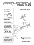
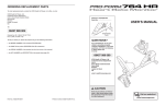
ORDERING REPLACEMENT PARTS
To order replacement parts, contact the ICON Health & Fitness, Ltd. office, or write:
ICON Health & Fitness, Ltd.
Customer Service Department
Unit 4, Revie Road Industrial Estate
Revie Road
Beeston
Leeds, LS118JG
UK
Model No. WETL01540
Serial No.
Serial Number Decal
Tel:
08457 089 009
Outside the UK: 0 (044) 113 387 7133
Fax: 0 (044) 113 387 7125
To help us assist you, please be prepared to give the following information:
QUESTIONS?
• The MODEL NUMBER of the product (WETL01540)
As a manufacturer, we are committed to providing complete
customer satisfaction. If you
have questions, or if there are
missing parts, please call:
• The NAME of the product (WESLO CARDIOSTRIDE PLUS treadmill)
• The SERIAL NUMBER of the product (see the front cover of this manual)
• The KEY NUMBER and DESCRIPTION of the part(s) needed (see page 10)
8457 089 009
Or write:
ICON Health & Fitness, Ltd.
Customer Service Department
Unit 4
Revie Road Industrial Estate
Revie Road
Beeston
Leeds, LS118JG
UK
e-mail: [email protected]
CAUTION
WESLO is a registered trademark of ICON IP, Inc.
Part No. 221778 R1004A
Printed in China © 2004 ICON IP, Inc.
Read all precautions and instructions in this manual before using
this equipment. Save this manual
for future reference.
USER’S MANUAL
TABLE OF CONTENTS
EXPLODED DRAWING—Model No. WETL01540
IMPORTANT PRECAUTIONS . . . . . . . . . . . . . . . . . . . . . . . . . . . . . . . . . . . . . . . . . . . . . . . . . . . . . . . . . . . . . . . . 2
BEFORE YOU BEGIN . . . . . . . . . . . . . . . . . . . . . . . . . . . . . . . . . . . . . . . . . . . . . . . . . . . . . . . . . . . . . . . . . . . . . . 3
ASSEMBLY . . . . . . . . . . . . . . . . . . . . . . . . . . . . . . . . . . . . . . . . . . . . . . . . . . . . . . . . . . . . . . . . . . . . . . . . . . . . . . 4
TREADMILL OPERATION . . . . . . . . . . . . . . . . . . . . . . . . . . . . . . . . . . . . . . . . . . . . . . . . . . . . . . . . . . . . . . . . . . . 6
MAINTENANCE AND TROUBLESHOOTING . . . . . . . . . . . . . . . . . . . . . . . . . . . . . . . . . . . . . . . . . . . . . . . . . . . . 8
CONDITIONING GUIDELINES . . . . . . . . . . . . . . . . . . . . . . . . . . . . . . . . . . . . . . . . . . . . . . . . . . . . . . . . . . . . . . . 9
PART LIST . . . . . . . . . . . . . . . . . . . . . . . . . . . . . . . . . . . . . . . . . . . . . . . . . . . . . . . . . . . . . . . . . . . . . . . . . . . . . . 10
EXPLODED DRAWING . . . . . . . . . . . . . . . . . . . . . . . . . . . . . . . . . . . . . . . . . . . . . . . . . . . . . . . . . . . . . . . . . . . . 11
ORDERING REPLACEMENT PARTS . . . . . . . . . . . . . . . . . . . . . . . . . . . . . . . . . . . . . . . . . . . . . . . . . Back Cover
33
1
R1004A
34
6
27
2
5
40
32
3
34
33
35
31
32
IMPORTANT PRECAUTIONS
36
10
31
28
WARNING: To reduce the risk of serious injury, read the following important precau-
6
tions before using the treadmill.
39
8. The treadmill should not be used by persons
weighing over 115 kg (250 lbs.). Never allow
more than one person on the treadmill at a
time.
1. It is the responsibility of the owner to ensure
that all users of the treadmill are adequately
informed of all warnings and precautions.
19
6. The roller guards (see the drawing on page 3)
must be 3 mm (1/8 in.) from the rear roller.
Adjust the roller guards, if necessary.
14. If you feel pain or dizziness whilst exercising,
stop immediately and begin cooling down.
7. Keep children under the age of 12 and pets
away from the treadmill at all times.
7
This is especially important for persons over the age of 35 or persons with pre-existing health problems. Read all instructions before using this product. ICON assumes no responsibility for personal
injury or property damage sustained by or through the use of this product.
2
37
42
7
25
23
14
16
15
44
22
43
7
7
17
38
23
30
WARNING: Before beginning this or any exercise program, consult your physician.
7
16
24
8
13
45
42
12. Do not place hands or feet under the treadmill whilst it is in use.
13. Always hold the handrail when mounting,
dismounting, or exercising on the treadmill.
7
7
29
11. Do not use the treadmill if it is not working
properly.
5. Inspect and properly tighten all parts of the
treadmill regularly; replace any worn parts
immediately.
9
7
41
10. Always wear athletic shoes when using the
treadmill; do not use the treadmill with bare
feet, wearing only stockings, or in sandals.
4. Place the treadmill on a level surface, with at
least 2.5 m (8 ft.) of clearance behind it and
0.5 m (2 ft.) on each side. To protect the floor
or carpet from damage, place a mat under the
treadmill.
9
18
13
37
9. Wear appropriate clothes when exercising.
Do not wear loose clothes that could become
caught on the treadmill.
4
8
11
3
13
37
10
2. Use the treadmill only as described.
3. This treadmill is intended for in-home use
only. Do not use the treadmill in a commercial, rental, or institutional setting.
21
12
15
7
44
20
26
22
7
17
11
38
A cool-down, consisting of five to ten minutes of
stretching. Stretching after exercise is effective for
increasing flexibility and helps to offset problems
caused when you stop exercising suddenly.
Instead of waiting for a convenient time to exercise,
plan a specific time. The morning hours work well for
many, and the self-discipline required to rise early and
exercise increases productivity throughout the day. For
others, exercising before dinner helps them to relax.
Whatever time you choose, be consistent.
EXERCISE FREQUENCY
To maintain or improve your condition, plan three
workouts each week, with at least one day of rest after
each workout. After a few months of regular exercise,
you may complete up to five workouts each week, if
desired.
The key to success is to make exercise a regular and
enjoyable part of your everyday life.
PART LIST—Model No. WETL01540
Key No. Qty.
1
2
3
4
5
6
7
8
9
10
11
12
13
14
15
16
17
18
19
20
21
22
23
24
25
1
1
3
1
1
1
10
2
1
2
1
1
4
1
2
2
2
1
1
1
1
2
2
1
1
Description
26
27
28
29
30
31
32
33
34
35
36
37
38
39
40
41
42
43
44
45
#
#
Thank you for selecting the new WESLO® CARDIOSTRIDE PLUS treadmill. The CARDIOSTRIDE PLUS
treadmill is designed to let you enjoy effective cardiovascular workouts in the comfort and convenience of
your home. And when the CARDIOSTRIDE PLUS
treadmill is not in use, it can be folded up, requiring
less than half the space of other treadmills.
ing this manual, please call our Customer Service
Department at 08457 089 009. To help us assist you,
please note the product model number and serial
number before calling. The model number is
WETL01540. The serial number can be found on a
decal attached to the treadmill (see the front cover of
this manual to find the location of the decal).
For your benefit, read this manual carefully before
using the treadmill. If you have questions after read-
Before reading further, please familiarise yourself with
the parts that are labelled in the drawing below.
Console
R1004A
Key No. Qty.
Console
Handrail Wire
M4 x 12mm Screw
Storage Pin
Handrail
Reed Switch/Wire
M5 x 20mm Bolt
Frame Endcap
Front Roller/Flywheel
M5 x 10mm Bolt
Clip
Magnet
M8 Nylon Nut
Base
Base Pad
Roller Guard
Base Endcap
Walking Belt
Walking Platform
Hex Key
Spring Clip
Rear Roller Adjustment Bolt
Rear Roller Washer
Frame Endcap, Left
Rear Roller
BEFORE YOU BEGIN
1
1
1
1
1
2
2
4
4
1
1
4
4
1
1
1
4
1
2
1
1
1
Warning Decal
Description
Wrench
Battery Cover
Hood
Frame
Adhesive Clip
Handrail Endcap
Handrail Foam Grip
M8 x 15mm Bolt
M8 Washer
Left Upright
Right Upright
M8 Curved Washer
M8 x 50mm Bolt
Grommet
Warning Decal
Platform Cover, Left
M5 x 16mm Bolt
Frame Endcap, Right
Endcap Foot
Platform Cover, Right
Lubricant Pack
User’s Manual
Handrail
The decal shown above has been
placed on the treadmill in the location
shown. If the decal is missing or illegible, call our Customer Service
Department at 08457 089 009 and
order a free replacement decal. Apply
the decal in the location shown.
Storage Pin
Hood
Walking Belt
Roller Guards
# These parts are not illustrated.
Specifications are subject to change without notice. See the back cover of this manual for information about
ordering replacement parts.
10
Rear Roller Adjustment Bolts
3
ASSEMBLY
CONDITIONING GUIDELINES
The help of a second person is recommended. Set the treadmill in a cleared area and remove all packing
materials. Do not dispose of the packing materials until assembly is completed. Assembly requires only the
included hex key
and wrench
.
The following guidelines will help you to plan your
exercise program. Remember that proper nutrition and
adequate rest are essential for successful results.
1. Identify the Right Upright (36), which has a single hole in
the indicated location. Hold the Right Upright against the
Base (14) as shown, and orient the Right Upright so the
two indicated holes are on the side shown.
1
WARNING:
Holes
Before beginning this
or any exercise program, consult your physician. This is especially important for individuals over the age of 35 or individuals with preexisting health problems.
36
37
Attach the Right Upright (36) to the Base (14) with two
M8 x 50mm Bolts (38), two M8 Curved Washers (37),
and two M8 Nylon Nuts (13) as shown. Make sure that
the Curved Washers are turned so they conform to the
curve of the Base. Do not tighten the Nylon Nuts yet.
Hole
14
If your goal is to strengthen your cardiovascular system, your exercise must be “aerobic.” Aerobic exercise
is activity that requires large amounts of oxygen for
prolonged periods of time. This increases the demand
on the heart to pump blood to the muscles, and on the
lungs to oxygenate the blood. For effective aerobic
exercise, adjust the intensity of your exercise until
your heart rate is near the highest number in your training zone.
35
WHY EXERCISE?
37
37
38
Aerobic Exercise
Holes
13
Attach the Left Upright (35) to the Base (14) in the same
way. Make sure that the Left Upright is oriented so the
two indicated holes are on the side shown. Do not tighten the Nylon Nuts yet.
the first few minutes of exercise, your body uses easily accessible carbohydrate calories for energy. Only
after the first few minutes does your body begin to use
stored fat calories for energy. If your goal is to burn
fat, adjust the intensity of your exercise until your
heart rate is between the lower two numbers in your
training zone as you exercise.
Exercise has proven essential for good health and
well-being. A well-rounded exercise program helps to
develop a stronger and more efficient heart, improved
respiratory function, increased stamina, better weight
management, increased ability to handle stress, and
greater self-esteem.
13
38
37
HOW TO MEASURE YOUR HEART RATE
EXERCISE INTENSITY
2. Raise the Left Upright (35) and the Right Upright (36) to
the position shown.
2
Whether your goal is to burn fat or to strengthen your
cardiovascular system, the key to achieving the
desired results is to exercise with the proper intensity.
The proper intensity level can be found by using your
heart rate as a guide. The chart below shows
recommended heart rates for fat burning and aerobic
exercise.
36
35
3. Attach the Hood (28) to the front of the Frame (29) with
two M5 x 10mm Bolts (10).
3
28
10
29
4. See drawing 4a. Hold the front of the Frame (29)
between the Left Upright (35) and the Right Upright (not
shown). Locate the small incline knob on each side of
the Frame. Slide the knobs into one of the three sets of
slots in the brackets on the Uprights. Make sure that
the knobs are fully inserted at the same height.
10
4a
35
4b
View from
beneath
Knob
Look under the Frame (29) near the Left Upright (35).
See drawing 4b. Locate the Clip (11) attached to the
underside of the Frame. Insert the Reed Switch (6) into
the Clip as shown. Next, locate the Magnet (12) on the
left Flywheel (9). Turn the Flywheel until the Magnet is
aligned with the Reed Switch. Move the Reed Switch
so that there is a 3 mm (1/8 in.) gap between the
Reed Switch and the Magnet. Then, tighten the M4 x
12mm Screw (3) in the Clip.
4
To measure your
heart rate, stop exercising and place two
fingers on your wrist
as shown. Take a
six-second heartbeat
count, and multiply
the result by ten to
find your heart rate.
(A six-second count is used because your heart rate
drops quickly when you stop exercising.) If your heart
rate is too high, decrease the intensity of your exercise. If your heart rate is too low, increase the intensity
of your exercise.
9
Bracket
WORKOUT GUIDELINES
To find the proper heart rate for you, first find your age
near the bottom of the chart (ages are rounded off to
the nearest ten years). Next, find the three numbers
above your age. The three numbers are your “training
zone.” The lower two numbers are recommended
heart rates for fat burning; the highest number is the
recommended heart rate for aerobic exercise.
Each workout should include the following three important parts:
A warm-up, consisting of five to ten minutes of
stretching and light exercise. This will increase your
body temperature, heart rate, and circulation in preparation for exercise.
Burning Fat
Training zone exercise, including 20 to 30 minutes of
exercise with your heart rate in your training zone.
To burn fat effectively, you must exercise at the proper
intensity level for a sustained period of time. During
29
12
6
3
11
29
1/8”
9
MAINTENANCE AND TROUBLESHOOTING
Most problems can be solved by following the simple steps below. If further assistance is needed,
please call our Customer Service Department.
1. SYMPTOM: THE CONSOLE DOES NOT
FUNCTION PROPERLY
3. SYMPTOM: THE WALKING BELT SLIPS OR IS
OFF-CENTRE
a. If the walking
belt slips
when walked
on, use the
hex key to turn
both adjustment bolts
clockwise, 1/4
of a turn. When
the walking belt is correctly tightened, you should
be able to lift each side of the walking belt 5 to 7
cm (2 to 3 in.). Walk on the treadmill for a few
minutes. Repeat until the walking belt is properly
tightened. Be careful to keep the walking belt centred.
a. Replace the batteries in the console (see assembly step 6 on page 5).
b. Make sure that the reed switch is properly adjusted (see assembly step 4 on page 4).
c. Make sure that the handrail wire is plugged fully
into the wire on the console (see assembly step 7
on page 5).
d. The console, like most electronics, is susceptible
to static electricity build-up caused by certain
types of clothing or by the operation of the treadmill. If the display is blank or gives incorrect readings, apply an anti-static spray to the handrail.
Anti-static spray is available where laundry supplies are sold.
b. If the walking
belt has shifted to the left
side, use the
hex key to turn
the left adjustment bolt
clockwise, and
the right adjustment bolt counterclockwise, 1/4 of a turn each.
Be careful not to overtighten the walking belt.
Walk on the treadmill for a few minutes. Repeat
until the walking belt is centred.
2. SYMPTOM: THE WALKING BELT DOES NOT
MOVE SMOOTHLY
a. If the walking belt is
Walking
overtightBelt
ened, performance
may be
reduced and
the walking
belt may be
5–7 cm
permanently
Bolts
damaged.
Using the
hex key,
turn both rear roller adjustment bolts counterclockwise 1/4 of a turn. When the tension of the
walking belt is correct, you should be able to lift
each side of the walking belt 5 to 7 cm (2 to 3 in.).
Walk on the treadmill for a few minutes. Repeat
until the walking belt is properly tightened. Be
careful to keep the walking belt centred.
c. If the walking
belt has shifted to the right
side, use the
hex key to turn
the left adjustment bolt counterclockwise,
and the right
adjustment bolt clockwise, 1/4 of a turn each. Be
careful not to overtighten the walking belt. Walk
on the treadmill for a few minutes. Repeat until the
walking belt is centred.
5. Hold the Handrail (5) near the Left and Right Uprights (35,
36). Connect the Handrail Wire (2) to the Reed Switch
Wire (6). Insert the Wires down into the Left Upright.
5
33 34
5
2
Attach the Handrail (5) to the Uprights (35, 36) with four
M8 x 15mm Bolts (33) and four M8 Washers (34). Be
careful not to pinch the Wires (2, 6).
6
See step 1. Tighten the four M8 Nylon Nuts (13).
35
34
33
36
6. The Console (1) requires two “AAA” batteries. Alkaline
batteries are recommended. Press the indicated tab on
the Battery Cover (27), and remove the Battery Cover.
Insert two batteries into the two battery clips; make sure
that the negative (–) ends of the batteries are touching the springs in the battery clips.
6
Batteries
1
Tab
27
7. See drawing 7a. Hold the Console (1) near the Handrail
(5). Connect the wire on the Console to the Handrail
Wire (2). Attach the Console to the Handrail with two M4
x 12mm Screws (3). Make sure that the wires are not
pinched.
7a
7b
1
1
2
See drawing 7b. Press the Battery Cover (27) back onto
the Console (1).
3
8. Remove the paper backing from the Adhesive Clip (30).
Press the Adhesive Clip onto the Left Frame Endcap (24)
in the indicated location. Press the Hex Key (20) into the
Adhesive Clip.
5
27
8
Make sure that the walking belt is properly tightened (see
SYMPTOM 3 on page 8).
20
30
24
9. Make sure that all parts are properly tightened before you use the treadmill. To protect the floor or carpet,
place a mat under the treadmill.
8
5
INCLINE ADJUSTMENT
TREADMILL OPERATION
LUBRICATING THE WALKING PLATFORM
• Time—This mode displays the elapsed time.
Before the treadmill is used, the walking platform
should be lubricated. Open the included lubricant
packet. Reach under one side of the walking belt as
far as you can, and apply half of the lubricant to the
walking platform. Then, reach under the other side of
the walking belt and apply the remaining lubricant.
After you have applied the lubricant, walk on the
treadmill for a few minutes to spread the lubricant.
• Odometer—This mode displays the distance that
the walking belt has moved since batteries were
changed.
• Calorie—This mode displays the approximate number of calories you have burned.
• Scan—This mode displays the Speed, Distance,
Time, Odometer, and Calorie modes.
Follow the steps below to operate the console.
Apply
lubricant
here
2. Hold the treadmill
securely with your
right hand as
shown. Insert the
Storage Pin (4)
into the hole in the
right side of the
Right Upright (36)
and into the
Frame (29) as far
as it will go.
The incline of the treadmill can be adjusted to any of
three angles. To change the incline, first lift the front of
the Frame (29) so the small incline knobs on the sides
of the Frame slide out of the slots in the brackets on
the Uprights (35, 36). Raise or lower the Frame, and
slide the knobs into one of the three sets of slots in the
brackets. Make sure that the knobs are fully inserted at the same height.
35
Next, press the
ends of the Spring
Clip (21) together,
and slide the
Spring Clip onto
the end of the
Storage Pin (4).
36
Bracket
1. Turn on the power.
29
To turn on the power, press the console button or
begin walking. Note: If batteries were just installed,
the power will already be on.
When the power is
turned on, the Scan
mode will be selected and the SCAN
indicator will
appear. The conSCAN Indicator
sole will display the
Speed, Distance,
Time, Odometer, and Calorie modes, for about six
seconds each, in a repeating cycle.
STEP-BY-STEP CONSOLE OPERATION
Before the console can be operated, batteries must be
installed (see assembly step 5 on page 5). If there is a
thin sheet of plastic on the console, remove the plastic.
To select only the Speed, Distance, Time,
Odometer, or Calorie mode, press the console button until only the SPEED, DIST, TIME, ODO, or
CAL indicator appears in the display. Make sure
that the SCAN indicator does not appear.
To reset all modes (except for the odometer mode),
press the console button for about three seconds.
3. Turn off the power.
To turn off the power, simple wait for a few minutes.
If the walking belt is not moved and the console
button is not pressed for a few minutes, the power
will turn off automatically.
The console features six modes:
• Speed—This mode displays your speed, in miles
per hour.
• Distance—This mode displays the number of miles
you have walked.
6
36
29
21
4
LOWERING THE TREADMILL FOR USE
1. Hold the treadmill securely with your right hand as
shown in drawing 2 above. Press the ends of the
Spring Clip (21) together, and slide the Spring Clip
off the end of the Storage Pin (4). Pull out the
Storage Pin and pivot the treadmill down a few
inches. Then, reinsert the Storage Pin and reattach
the Spring Clip.
2. Track your progress with the six modes.
Apply
lubricant
here
2
CAUTION:
Make sure that the
incline knobs are fully inserted at the same
height.
2. Hold the treadmill firmly with both hands, and lower
the treadmill to the floor. CAUTION: To decrease
the possibility of injury, bend your legs and
keep your back straight.
FOLDING THE TREADMILL FOR STORAGE
When the treadmill is not in use, it can be folded to
the compact storage position. CAUTION: You must
be able to safely lift 25 pounds (11 kg) to raise,
lower, or move the treadmill. Follow the steps below
to fold the treadmill.
1. Hold the tread1
mill in the location shown.
CAUTION: To
decrease the
possibility of
injury, bend
your legs and
keep your back
straight. As
you raise the
treadmill, make
sure to lift with
your legs
rather than your back. Raise the treadmill to the
vertical position.
7