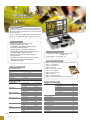
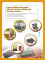
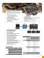
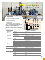
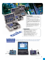
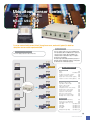
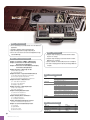
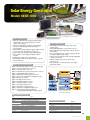
1
2014
www.manntel.com
High Technology
Training System
Man & Tel Co., Ltd.
Man & Tel Co., Ltd is a venture-enterprise company developing
high Technology Tranining System and communication terminals.
2
A group of RF Design / Antenna / Microwave Training System
Model: RFDT-1000 / MW-1000 / MW-2000 / MW-5000 / MATS-1000 / WATS-2002
A group of Mobile Communication Trainers
Model: MT-3000
13
A group of Network Communication Training System
Model: ERT-5000 / WLAN-TS-1000 / WLAN-VP-1000
17
23
A group of RFID Training System
Model: RFID-13.56 / RFID-EPC / RFID/USN-6000 / RFID-3000 / RFID-5000
A group of Bluetooth Telecom Training System
Model: BT-2007 / BT-3000 / BEHK-100 / MBS-100
32
A group of Ubiquitous Home Network Training System
Model: BHN-1000 / BCT-100 / UHN-3000 / UHN-5000
41
A group of Ubiquitous Sensor Control Traniners
Model: ZT-200 / USC-5000 / USC-7000 / USN-1000/1500
51
A group of Microprocessor Embedded Trainer
Model: MBT-100 / MBT-200 / MBPT-1000 / MBPT-2000 / ANDRO-1000
58
67
Renewable Energy Lab Equipment
PCTK-100 / SEGT-1000 / WEGT-1000 Blade Type / WEGT-1000 Hand Type
Man & Tel Co., Ltd.
A group of Basic Electronic Trainer
Model : ECTK-100 / BECK-1000 / DCTK-1000
72
A group of PLC Trainer
Model : PLC-1000 / FATS-5000
79
A group of Robot Training System
Model : MRT-1000 / RMR-1000
83
A Greeting from the CEO
Man & Tel is an INNO-BIZ
company and venture-enterprise
which develop high-tech educational
systems and medical devices and
equipment for rehabilitation
Man & Tel does the educational
equipment development business to
develop advanced educational
equipment in connection with IT
technology to contribute to education of commercialization
technology and state-of-the-art education.
Man & Tel does the medical device and equipment business for
rehabilitation to contribute to giving hope to patients suffering from
pain and their families and to making better world as well.
Man & Tel will continue to make every effort to be a company
beneficial to the society and move ahead with innovative and
challenging spirit along with flexible mind and utmost efforts in the
IT-convergence market which will lead the future.
All staffs of Man & Tel will return continuing innovation and better
equipment for your concern and encouragement and try to make
better world with you.
Thank you
President
Dr.
Kwang-Wook, Jung
1
www.manntel.com
A group of RF Design / Antenna / Microwave Training System
RFDT-1000 / MW-1000 / MW-2000 / MW-5000
MATS-1000 / WATS-2002
These equipments provide trainees with chance to design, manufacture and measure
microwave communication system by applying microwave designing theory. Also,
experiments on standing wave, fading, wave loss, doppler effect are provided to help
trainees understand characteristics and radio patterns of various antennas in addition to
wave features in mobile communication.
Wave and antenna
Training System
RF Signal Generator
RFSG-1000
WATS-2002
Antenna
Training System
microwave communication
Trainer
MATS-1000
Microwave
Experiment Kit
MW-2000 / MW-5000
RF Design
Technology Trainer
MW-1000
RFDT-1000
2
A
L e a d e r
Man & Tel Co., Ltd.
i n
n e w
T e c h n o l o g y
&
E d u c a t i o n
RF Design Technology Trainer
Model: RFDT-1000
RFDT-1000 Features
1. Helps users acquire basic RF circuit designing skills.
2. Helps users acquire RF module manufacturing skills.
3. Provides RF circuit measuring practices.
4. Provides chip components' value measuring
practices in high frequency band.
RFDT-1000 helps users understand basic and
important techniques of RF circuit design
through theories, manufacturing practices and
measuring practices.
RFDT-1000 Training contents
RFDT-1000 Functions
1) Understanding port extension skill.
2) Understanding how to measure chip impedance and
changes of the impedance.
3) Understanding principle of microstrip stub and impedance
calculation.
4) Understanding RF choke design and characteristic
measurement.
5) Impedance matching : L,C matching converter, Stub matching,
L,C Matching in transmission line.
6) LC filter1 : Understanding types and operation of low pass
filter, Implementing them on microstrip lines and
measuring characteristic values.
7) LC filter2: Designing&manufacturing band pass filter and
understand its characteristics.
8) Designing, manufacturing and tuning monopole antenna.
9) Designing microstrip patch antenna and understanding
power feed.
Chapter 1. Port Extension
Chapter 2. Measuring Chip Impedance
Chapter 3. Microstrip stub
Chapter 4. RF choke
Chapter 5. Impedance Matching 1
(using lumped element L, C)
Chapter 6. Impedance matching 2
(using a converter)
Chapter 7. Impedance matching 3
(using stub matching)
Chapter 8. Impedance matching 4 (using L and C
loaded on transmission line)
Chapter 9. LC low pass filter
Chapter 10. LC bandpass filter
Chapter 11. Monopole Antenna
Chapter 12. Microstrip Monopole Antenna
Chapter 13. Microstrip Patch Antenna 1
Chapter 14. Microstrip Patch Antenna 2
Chapter 15. Microstrip Patch Antenna 3
RFDT-1000 Components
RFDT-1000 Specifications
Items
Frequency Band
Impedance
Substrate material
PCB thickness
Dielectric constant
Operating Temperature
Relative Humidity
Specifications
20[Mhz] ~ 3[GHz]
50[Ω]
FR-4
0.8[mm]
4.4
-20℃ ~ 50℃
0% ~95%
Items
The finished PBA
Practice and manufacturing RF PCB
Chip component (R.L.C)
Cooper tape
Enameled wire
RF Cable
Textbook
Carrying bag
Chip components measuring JIG
Spec
46 kinds
A4
10MT
Q’ ty
52 types
56 ea
2,300ea (46kinds x 50ea)
1 ea
1 roll
2 ea
1 book
1 ea
1 set
3
www.manntel.com
A
L e a d e r
i n
n e w
T e c h n o l o g y
&
E d u c a t i o n
Microwave Communication Trainer
Model: MW-1000/ MW-2000 / MW-5000
An experimental equipment to educate Microwave Component
Design, Manufacturing, and Measuring techniques include
Microstrip line theory and Microwave device design theory.
4
Man & Tel Co., Ltd.
Microwave Experiment Kit
Model: MW-1000
MW-1000 Function
1) Study the microstrip line design theory
2) Study the basic theory of microwave component
3) Microwave component design & simulation
4) Microwave component manufacturing
5) Microwave component measurement
6) Microwave component analysis of characteristics
MW-1000 Characteristics
Experiment in Microwave component design and
Manufacturing & Measurement using microstrip line theory.
An Experimental Kit to educate basic concept of Microstrip Line
Design and Microwave Component Design.
Equipments are option.
MW-1000 Training Contents
Part I Introduction
Chapter 1 Microwave Experiment Kit Overview
Part II Experment of the Microwave passive Component
MW-1000 Specifications
Items
Frequency
Input Impedance
Connecting Loss
Substrate material
PCB thickness
Dielectric Constant
Specifications
2.0 [GHz ] , 2.4 [GHz ]
50 [ ohm ]
0.3 [ dB ]
Teflon
0.787 [ mm ]
2.5
Components
Main Components
Carriage bag
Textbook
Connector
50ohm terminator
Answer Sheet
9 EA
1 EA
1 EA
2 EA
2 EA
1 EA
Chapter 2 Tapered Line Impedance Transformer
Chapter 3 Wilkinson Power Divider
Chapter 4 Quadrature Hybrid Coupler
Chapter 5 Coupled Line Directional Coupler
Chapter 6 Folded Lange Coupler
Chapter 7 Unfolded Lange Coupler
Chapter 8 180°£ Hybrid
Chapter 9 Stepped Impedance Low Pass Filter
Chapter 10 Coupled Line Band Pass Filter
5
www.manntel.com
Microwave Communication Trainer (2.4GHz)
Model: MW-2000
AN 50178251 0001 [March 30, 2010]
MW-2000 Features
Allowing students to train themselves about Experiment in
microwave components design and manufacturing &
Measurement applying microstrip line theory and microwave
device design theory.
For these experiment, standard devices and Specification &
documents are supplied with software program as reference.
MW-2000 Functions
Communication using the Microwave system
Measurement in Microwave system
FSK Modulation & Demodulation in Microwave band
File transfer and data transmission
Understanding of the microstrip line design theory
Understanding of the basic theory of microwave devices
Design and simulation of Microwave devices
Experiments in manufacturing and measurement of
Microwave devices.
Signal Generator and Spectrum Analyzer can be used for
measuring the wave form of all the substrates
manufacturing by students.
MW-2000 Specifications
2.4[GHz] ~ 2.5[GHz]
FSK
4800 ~ 14400[bps]
+ 4.5 [dBm] Max
50 [ohm]
Rogers RO4003C
0.508 [mm]
3.38
2) Module Specification
Low Noise Aplifier
Power Divider
Band Pass Filter(2.4GHz)
Band Pass Filter (2.5GHz)
RF Amplifier
Antenna
(Transmitting & Receiving)
6
Man & Tel Co., Ltd.
Communication software : Microwave Communication
Program V1.0
Design Simulator : Ansoft Designer SV
MW-2000 Training Contents
Chapter
Chapter
Chapter
Chapter
Chapter
Chapter
Chapter
Chapter
Chapter
Chapter
1) General Specification
Frequency band
Modulation
Bit rate
Output power
Impedence
Substrate material
PCB thickness
Dielectric constant
MW-2000 Application Program
1 Introduction to Microwave Communication Trainer
2 FSK Modulator
3 RF Amplifier
4 Antenna
5 Low Noise Amplifier
6 Power Divider
7 Band Pass Filter
8 Detector
9 FSK Demodulator
10 Microwave Communication Experiments
MW-2000 Components
Frequency band
Gain
Noise Figure
Input P1dB
Type
Frequency band
Return loss
Insertion loss
Type
Center Frequency
Return loss
Insertion loss
Type
Center Frequency
Return loss
Insertion loss
Frequency band
Gain
Input
Type
Center Frequency
Gain
VSWR
2.4~2.5 [GHz]
26 [dB]
2.5 [dB]
-25 [dBm]
2-way, Wilkinson
2.4~2.5 [GHz]
14 [dB]
0.5 [dB]
Edge-coupled
2.4 [GHz]
10 [dB]
7.0 [dB]
Edge-coupled
2.5 [GHz]
10 [dB]
7.0 [dB]
2.4~2.5 [GHz]
15 [dB]
-5 [dBm]
YAGI (PCB type)
2.45 [GHz]
9 [dBi]
1.5:1
Device
FSK Modulator
FSK Demodulator
RF Amplifier
Detector
Band Pass Filter 2.4GHz
Band Pass Filter 2.5GHz
Power Divider
Low Noise Amplifier
Yagi Antenna
DC Power Adaptor(1.2V / 1.5A)
DC Power Cable
RS-232C Cable
RF Cable
Carriage bag
Antenna Cable(75cm)
Antenna Supporter
SMA Adaptor
50 ohm Terminator
Software program
Textbook
Answer sheet (Included in CD)
Program CD
1EA
1EA
2EA
2EA
1EA
1EA
1EA
1EA
2EA
2EA
2EA
2EA
3EA
1EA
2EA
2set
6EA
1EA
1EA
1EA
1EA
1EA
Microwave Communication Trainer (5.8GHz)
Model: MW-5000
MW-5000 Functions
- Communication using the Microwave system
- Measurement in Microwave system
- FSK Modulation & Demodulation in Microwave band
- File transfer and data transmission at 5.8GHz
- Understanding of the microstrip line design theory
- Understanding of the basic theory of microwave devices
- Design and simulation of Microwave devices
- Experiments in manufacturing and measurement of
Microwave devices.
- Signal Generator and Spectrum Analyzer can be used for
measuring the wave form of all the substrates
manufacturing by students.
MW-5000 Application Program
MW-5000 Features
Allowing students to train themselves in microwave
components design and manufacturing & measuring by
using Passive and Active devices and program at 5.8GHz.
For these experiment, standard devices and specification
& documents are supplied with software program as
reference.
MW-5000 Specifications
1) General Specification
Frequency band
Modulation
Bit rate
Output power
Impedence
Substrate material
PCB thickness
Dielectric constant
5.75[GHz] ~ 5.85[GHz]
FSK
4800 ~ 14400[bps]
+ 4.5 [dBm] Max
50 [ohm]
TLY-5A-0200-CH/CH
0.508 [mm]
2.17
Power Divider
Band Pass Filter(5.7GHz)
Band Pass Filter (5.8GHz)
RF Amplifier
Antenna
(Transmitting & Receiving)
MW-5000 Training Contents
Chapter 1 Introduction of Microwave Communication Trainer
Chapter 2 FSK Modulator
Chapter 3 RF Amplifier
Chapter 4 Antenna
Chapter 5 Low Noise Amplifier
Chapter 6 Power Divider
Chapter 7 Band Pass Filter
Chapter 8 Detector
Chapter 9 FSK Demodulator
Chapter 10 Microwave Communication Experiments
MW-5000 Components
Device
2) Module Specification
Low Noise Amplifier
Communication software : Microwave Communication
Program V1.0
Design Simulator : Ansoft Designer SV
Frequency band
Gain
Noise Figure
Type
Frequency band
Return loss
Type
Center Frequency
Return loss
Insertion loss
Type
Center Frequency
Return loss
Frequency band
Gain
Input
Type
Center Frequency
Gain
VSWR
5.75~5.85 [GHz]
26 [dB]
2.5 [dB]
2-way, Wilkinson
5.7~5.9 [GHz]
14 [dB]
Edge-coupled
5.7 [GHz]
14 [dB]
0.5 [dB]
Edge-coupled
5.8 [GHz]
10 [dB]
5.75 ~ 5.85 [GHz]
14 ± 1 [dB]
-5 [dBm]
YAGI (PCB type)
5.8 [GHz]
9 [dBi]
1.5:1
FSK Modulator
FSK Demodulator
RF Amplifier
Detector
Band Pass Filter 5.7GHz
Band Pass Filter 5.8GHz
Power Divider
Low Noise Amplifier
Yagi Antenna
DC Power Adaptor
DC Power Cable
RS-232C Cable
RF Cable
Carriage bag
Antenna Cable
Antenna Supporter
SMA Adaptor
50 ohm Terminator
Software program
Textbook
Answer sheet (Included in CD)
Program CD
1EA
1EA
3EA
2EA
1EA
1EA
1EA
1EA
2EA
2EA
2EA
2EA
3EA
1EA
2EA
2set
7EA
1EA
1EA
1EA
1EA
1EA
7
www.manntel.com
A
L e a d e r
i n
n e w
T e c h n o l o g y
Antenna
Training System
Model: MATS-1000
MATS-1000 includes RF Signal source of 0.3~6GHz.
It’s used to educate Antenna Characteristics, Gain, Radiation Pattern,
Impedance Matching and to Design & Manufacture Antenna.
8
Man & Tel Co., Ltd.
&
E d u c a t i o n
Antenna Training System
MATS-1000 Features
Model: MATS-1000
1. RF signal generator is included
2. Practice for Antenna characteristics is possible
3. Signal frequency and Output power is variable.
4. Suitable for training Antenna design, manufacturing,
measurement.
5. Practice is possible without extra measuring
equipment
6. Auto calibration is included to set maximum input
power position.
MATS-1000 Training contents
Part 1. Introduction and Installation of Program
Chapter 1. Introduction of system
Chapter 2. Program Installation and Instruction
Part 2. Practice for Antenna characteristics
Chapter 3. Practice for Dipole antenna
Chapter 4. Practice for Yagi antenna
Chapter 5. Practice for Monopole antenna
Chapter 6. Practice for Loop antenna
Chapter 7. Practice for Ceramic Chip antenna
Chapter 8. Practice for Inverted F antenna
Chapter 9. Practice for Patch and Array Patch antenna
Part 3. Practice for antenna Impedance matching and
antenna Gain measurement
Chapter 10. Practice for antenna Impedance matching
Chapter 11. Practice for antenna Gain measurement
Part 4. Practice for antenna Design and Manufacture
Chapter 12. Manufacture of Dipole antenna
Chapter 13. Manufacture of Loop antenna
Chapter 14. Manufacture of Yagi antenna
MATS-1000 Specifications
Items
RF
Frequency
Output power
AGC
Oscillation
Impedance
Supplied
Antenna Types
Control
Practice for Antenna
Manufacturing
Control Method
Antenna Angle Control
Angle Control Range
Motor Rotation
Specifications
1) Variable in 300MHz~3000MHz,
2) Variable in 5.0~6.0GHz
5 ~ -15dBm
25 [dB]
PLL frequency synthesized
50[ohm]
450 MHz : Dipole x2(PCB)
915 MHz : Dipole x2, Monopole
2.4 GHz : Dipole x2, Chip, Patch, Yagi x2,
Inverted F, Array Patch, Loop
5.6 GHz : Horn[Option], 5.8GHz Yagi× 2
Yagi, Loop, Dipole
Micro-Controller
360˚, 3600 step
0.1˚ / Step
0~360˚
Front, Back, Step
MATS-1000 Functions
1. Practice for Antenna characteristics
1) Practice for the Radiation pattern [Supplying Antenna]
- Yagi antenna
- Chip antenna
- Dipole antenna
- Monopole antenna
- Loop antenna
- Patch antenna
- Inverted F antenna
- Array Patch antenna
2) Practice for the Antenna characteristics by varying
source frequency
- Resonance frequency
-Gain
3) Practice for Designing, Manufacturing and Measuring
the following;
- Yagi antenna
- Loop antenna
- Dipole antenna
- Practice in GUI Environment
2. Practice in GUI Environment
MATS-1000 Components
RFSG-1000
Manufacturing antenna
Antenna Base
Wrench set
Carrying Bag
50ohm Terminator
1Set
3EA
2EA
1Set
1EA
2EA
Text Book
Antenna
Program CD
Antenna Fixing Bracket
Horn Antenna [Option]
RF Signal
Model:
Generator
1EA
18EA
1EA
2EA
1EA
RFSG-1000
RFSG-1000 Features
1. Role of High-Frequency Signal Geneator
2. Variable Output Power
3. Vriable Frequency
RFSG-1000 Specifications
Items
Source Frequency
Output Power
Oscillation
Impedance
Spec
1) 300~3000MHz, -15 ~ +5dBm
2) 5.0~6.0 GHz , -10 ~ +5dBm
5 ~ -15dBm
PLL frequency synthesized
50[ohm]
RFSG-1000 Components
Main System
RF Coaxial Cable
1 Unit
2 EA
RS-232 Cable
Adapter
2EA
1EA
9
www.manntel.com
A
L e a d e r
i n
n e w
T e c h n o l o g y
Wave and Antenna
Training System
Model: WATS-2002
An experimental equipment to educate electromagnetic wave propagation
in mobile communication and Antenna characteristics such as
Radiation patterns, Fading and Propagation loss, etc.
50178247 0001 [March 30, 2010]
10
Man & Tel Co., Ltd.
&
E d u c a t i o n
Wave and Antenna Training System
Model: WATS-2002
Antenna
Antenna Mounter
Main Body
Antenna Base
Control Unit (Computer)
WATS-2002 Features
Spectrum Analyzer and Laptop are purchased optionally.
Wave and Antenna
Training System
Model. WATS-2002
An experimental equipment to educate electromagnetic wave propagation in mobile
communication and Antenna characteristics such as Radiation patterns, Standing wave,
Fading(Phase delay and attenuation), Doppler frequency and Propagation loss.
914MHz
WATS-2002 Experiment Steps
Power S/W
2450MHz
Most experiment is possible without extra
measuring equipment.
Antenna characteristics measurement.
Mobile communication propagation experiment.
Propagation modeling & Loss Simulation.
Auto Calibration.
User interface with GUI windows.
Test Points
LED
1) Antenna characteristic Experiment
Radiation pattern measurement
Antenna manufacturing and characteristic measurement
2) Mobile communication propagation characteristics
experiment
Fading experiment (phase delay, power attenuation, multi path)
Standing wave experiment
Time delay experiment
Doppler frequency experiment
3) Mobile communication propagation environments simulation
Propagation model simulation
Reset S/W
11
www.manntel.com
Wave and Antenna
Training System
Model. WATS-2002
WATS-2002 Training Contents
Part 1. Introduction and Installation of Program
Chapter 1 Introduction of WATS-2002
Chapter 2 Program Installation and Instruction
Part 2. Antenna characteristics Experiment
Chapter 3 Dipole Antenna Characteristics Experiment
Chapter 4 Yagi Antenna Characteristics Experiment
Chapter 5 Monopole Antenna Characteristics Experiment
Chapter 6 Loop Antenna Characteristics Experiment
Chapter 7 Ceramic Chip Antenna Characteristics Experiment
Chapter 8 Inverted F Antenna Characteristics Experiment
Chapter 9 Patch and Array Patch Antenna Characteristics Experiment
Part 3. Antenna Design and Manufacturing Experiment
Chapter 10 Dipole and Yagi Antenna Production and Analysis Experiment
Chapter 11 Loop Antenna Production and Analysis Experiment
Part 4. Mobile Communication Propagation Experiment
Chapter 12 Phase Delay Experiment
Chapter 13 Power Attenuation Characteristic Experiment
Chapter 14 Multi-Path Fading Experiment
Chapter 15 Time Delay and Doppler Effect Experiment
Chapter 16 Standing Wave Experiment
WATS-2002 Specifications
Items
RF
Specifications
914 [MHz] , 2.45 [GHz]
+4.5 [dBm] Max
PLL
50 [ohm]
40 [dB]
21.7 [MHz]
Yagi, Chip, Dipole, Monopole, Loop,
Patch, Inverted F, Array Patch
Micro-controller
360° , 400 steps
0.9° / steps
0~360°
Auto Calibration
Front, Back, Step
Frequency
Output Power
Local Oscillation
Impedance
AGC Dynamic Range
IF
Antenna
Part 5. Mobile Communication Propagation Environments Simulation
Chapter 17 Propagation Modeling and Propagation Loss Experiment
Control
Control Method
Antenna Angle Control
Angle Control Range
Position Calibration
Motor Rotation
WATS-2002 Components
Main body
Carriage Bag
Textbook
Antenna
Training Antenna
Antenna Base
RF Coaxial Cable
12
Man & Tel Co., Ltd.
1 EA
1 EA
1 EA
14 EA
3 EA
2 EA
3EA
50ohm Terminator
RS-232C Cable
Adaptor
Wrench
Program CD(Multi-media CD)
Antenna Fixing Bracket
2 EA
2 EA
1 EA
1 SET
1 EA
2 EA
A group of Mobile Communication Trainers
MT-3000
These equipments provide instructions on basic concepts of mobile
communication to students who study for mobile communication,
information technology and electronics.
Equipments for experiment
on mobile communication
MT-3000
A
L e a d e r
i n
n e w
T e c h n o l o g y
&
E d u c a t i o n
www.manntel.com
13
A
L e a d e r
i n
n e w
T e c h n o l o g y
MOBILE Telecom Trainer
Model: MT-3000
An experimental equipment to educate basic concept of the Full Duplex
wireless system and Mobile telecommunication.
[November 23, 2010]
14
Man & Tel Co., Ltd.
&
E d u c a t i o n
MOBILE Telecom Trainer
Model: MT-3000
MT-3000 Features
Full Duplex Voice & Data Communication
Half Duplex Voice & Data Communication
Practice of RF interference & mobile environment
Chatting by using Computer.
Board level and full system level experiment is
available using one set
Auto Mode and Manual mode can be selectable
Built-in Software equal to the Commercial Products.
Operating like as Commercial Mobile
Products in Auto Mode.
16 x 2 Character LCD.
LED Indicator.
Over Charge Protection.
〈 MT-3000-B Base Set 〉
〈 MT-3000-M Mobile Set 〉
MT-3000 Experiment Steps
1) Board Unit Module Experiment : Power, Audio, Control, Radio Frequency
2) Half Duplex Audio and Data Experiment : Half Duplex Transmitting and Receiving Experiment
3) Full Duplex Audio and Data Experiment : Full Duplex Communication Experiment
4) Mobile Environmental Experiment : RF Interference Experiment Among Systems
5) Data Communication : Chatting Practice by Serial Communication.
15
www.manntel.com
MOBILE
Telecom Trainer
MT-3000 Training Contents
Model: MT-3000
Part 1. Introduction of Products
Experiment 1. Full Duplex Mobile Telecommunications
Lab Equipment
Experiment 2. Power Part
Part 2. Audio Frequency Part
Experiment 3. Condenser Mike and Limiter
Experiment 4. Compressor
Experiment 5. Pre-emphasis and De-emphasis
Experiment 6. Expander
Experiment 7. Band-Pass Filter and Squelch Circuit
Part 3. Radio Frequency Part
Experiment 8. PLL Oscillator Ⅰ
Experiment 9. PLL Oscillator Ⅱ
Experiment 10. Transmitting Part
Experiment 11. Receiving Part
Part 4. Control Part
Experiment 12. Microcomputer and Key Matrix Control
Peripheral Circuits
Part 5. Full Duplex Communication
Experiment 13. Half-Duplex Transmitting Integration
Experiment
Experiment 14. Half-Duplex Receiving Integration
Experiment
Experiment 15. Full-Duplex Integration Experiment
Experiment 16. Radio Environment Experiment
Experiment 17. Chatting by using Serial communication
MT-3000 Components
Mobile set
Carriage Bag
Handset
Adaptor
MT-3000 Specifications
Items
RF
Communication Method
Channel Access
Frequency Range
Output Power
Channels
Bandwidth / Channel
Modulation
Frequency Stability
Receiving Sensitivity
Auto Channel Scan Time
Data rate
Specifications
Full Duplex / Half Duplex
Multi Channel Access
Base
46.51 ~ 46.97 [MHz]
Remote 49.67 ~ 49.99 [MHz]
+4.5 [dBm] Max
15 Duplex Channels
25 [kHz]
FM
≤
± 5 [ppm]
Over 20 [dB] SINAD (at -100 [dBm])
≤ 200 [ms]
2,400 bps
MobileTelecom
Board Level Kit
Model:
MT-1500
MT-1000 Features
Allowing students to train themselves about
board manufacturing.
Learning about parts and product through actual
manufacturing.
Capable of operation measurement for each circuit.
Providing PCB designed with patterns.
Capable of Full Duplex voice conversation training.
Capable of Half Duplex voice conversation training.
Capable of Detailed Module Training at
Single Board Level.
Training in full set experiment with four
boards combined.
16
Man & Tel Co., Ltd.
Kit Components
1) Parts for Radio Frequency board
2) Parts for Audio Frequency board
3) Parts for Power board
4) Parts for Control board
5) Microcomputer including software program
6) Handset, adaptor, coaxial cable, etc.
7) Operation Manual
8) Textbook
List of Training Contents and Specifications
※ Same as MT-3000 model.
1 EA
1 EA
2 EA
2 EA
Base set
Textbook
Program CD(Multi-media CD)
RS-232C Cable
1 EA
1 EA
1 EA
2 EA
A group of Network Communication Training System
ERT-5000 / WLAN-TS-1000
WLAN-VP-1000
Wireless LAN Video
Processing Training System
Wireless LAN Training
System
WLAN-VP-1000
Embedded Network
programming and
Configuration
WLAN-TS-1000
ERT-5000
A
L e a d e r
i n
n e w
T e c h n o l o g y
&
E d u c a t i o n
www.manntel.com
17
A
L e a d e r
i n
n e w
T e c h n o l o g y
&
E d u c a t i o n
Wireless LAN Training System
Model: WLAN-TS-1000
WLAN-TS-1000 Features
1) Wi-Fi practice board
Wireless standards : IEEE802.11b/g/n
Frequency range : 2.421~2.485GHz
Data transmitting speed : 54Mbps ~ 1Mbps
Serial cable connection to Wi-Fi Server
Target Socket connection : Max 5 sec
Best security via 64/128bit WEP, WPA, WPA2
Simple AT command practice
2) Wireless LAN Protocol Analyzer
The ability to capture : Protocol capture to 802.11
and higher-layer
Frequency band : b/g/n
Number of Protocol analyzer : Max 256
Operating system : Windows XP
Others : Channel switching function
WLAN-TS-1000 Functions
1) Wireless LAN technology
- Learn Wireless LAN technology
- IEEE802.11 b/g/n
- Wi-Fi configuration and demo
2) Wireless LAN configuration practice and Protocol
analyzing practice
- Wi-Fi operation
- Protocol analyzer
- Wireless LAN Packet Analyzer
Ethernet
System Configuration
Access Point
WLAN Protocol Analyzer
Serial Cable
WLAN Card
Operating Mode
Computer
18
Man & Tel. Co., Ltd,
WLAN Practice Board
Max :256
WLAN-TS-1000 is a training system to educate the basic WLAN technology, WLAN protocol
analysis, integrated operation with peripheral devices.
Wireless LAN Training System is a advanced technology education equipment for Wi-Fi
environment set-up experiment and protocol analyzing training through lessons about
Wireless LAN (802.11 b/g) concept and experimental environment configuration practices.
WLAN-TS-1000 Specifications
1) Wi-Fi Evaluation Board
- Wireless
Item
Wireless Standard
Frequency Range
Output Power
(Tolerance(+/-1dBm)
Receive Sensitivity
Data Rates
Modulation
Description
IEEE802.11b/g
2.412~2.485GHz
10 dBm(10mW)
-92dBm@1Mbps
-90dBm@2Mbps
54Mbps-1Mbps
BPSK at 1Mb/s, QPSK at 2Mb/s
- Hardware
Item
Interface
Temperature
Humidity
Serial
Power
Power Consumption
Dimension
Description
UART(2), SPI(Master, Slave), I2C(2), JTAG(5), Alarm(2), GPIO(6), Power
U.FL(wireless)
Operation : -40℃ ~85℃
Operation : 10% to 90%, Non-Condensing
Storage : 5% to 90%, Non-Condensing
Baud Rate : 1200bps~921,600bps, (Default : 115,200bps)
Stop bits : 1
Parity : None, Odd, Even
Flow Control : XON/XOFF(software), CTS/RTS(hardware), none
3~3.63V dc
100mA@operating mode, 7uA@sleep mode
30mm × 27mm × 3.6mm
- Software
Item
Description
Serial Command Standard
ITU V.25ter AT Command Set
Operation Mode
Infrastructure, Ad-Hoc
Protocol
ARP, UDT, TCP, Telent, ICMP, DHCP, PPPoE, BOOTP,
HTTP, SMTP, TFTP, DNS, SNMPv1, IPv4
Security
WEP 64/128big, WPA/WPA2(Enterprise) EAP-TLS,
FAST, TTLS, PEAPv0/v1, 802.1× (Radius), SSL/TLS
Management
Console, User Interface
2) Access Point
- Wireless
Item
Standard
Access type
Transmission method
Frequency Range
Data rate
Set up Environment
Antenna
Security
Protocol
Wireless bridge
Description
IEEE 802.11b/g, 802.11n (draft 2.0)
CSMA / CA
DSSS, OFDM, Half Duplex
2.412-2.472MHz (13채널)
802.11b - Max. 11Mbps
802.11g - Max. 54Mbps
802.11n - Max. 300Mbps (2Tx-2Rx-2CH bonding)
Wireless LAN connection wizzard, AP search, join, authentication,
association function, wireless channel selection
802.11b/g/n external type(2eas)
128/64bit WEP, WPA-PSK, WPA2PSK, WPS
between Wireless and wired : L2 level bridging
WDS supported
- WAN Specifications
Item
Standard
Access type
Transmission method
Connection type
Security
Connector
Data rate
Description
IEEE 802.3 / 802.3u(10Base-T, 100Base-TX)
CSMA / CD
4B5B MLT3 for 100Base-TX, Manchester coding fo 10Base-T
1Static IP, DHCP Client, PPPoE
VPN server (PPTP) included
Auto MDI-X, RJ-45
160Mbps Max (LAN-to WAN, real time test data)
- LAN
Item
LAN Switch
Connector
Special features
Description
Store/Forward Switching, Wire-rate Switching
Auto MDI-X, RJ-45, 4 port
QoS, VPN Server, Worm Virus check,
- Dementions & power
Size
Power
146 × 93 × 24 (mm)
external DC adaptor
3) Wireless LAN Protocol Analyzers
WLAN-TS-1000 Training contents
Part 1. Introduction to Wireless LAN technology
Chap 1. Introduction to Wireless LAN
Chap 2. Wireless LAN Fundamentals
Chap 3. Wireless LAN Technology(IEEE802.11 b/g/n)
Part 2. System Experimental Environment
Chap 4. System configuration and setting
- Configuration and setting of wireless
experimental boards
- Configuration and setting of protocol analyzer
Part 3. WLAN packet structure and protocol analysis
Chap 6. WLAN packet analysis
Chap 7. WLAN search protocol analysis
Chap 8. WLAN certification protocol analysis
Chap 9. WLAN conjunction protocol analysis
Chap 10. WLAN internet protocol analysis
Item
Capture Capability
Frequency Bands
Operating Systems
Description
Full 802.11 Capture and upper layer protocols
b/g/n.
Windows XP
Etc : Channel switching capability
4) Wireless LAN Card
* IEEE 802.11b/g, 802.11n (draft 2.0) compatible
WLAN-TS-1000 Components
WLAN Evaluation board
WLAN Protocol Analyzer
Wi-Fi Access Point
WLAN Card
Textbook
2 ea
1 ea
1 ea
1 ea
1 book
19
www.manntel.com
A
L e a d e r
i n
n e w
T e c h n o l o g y
&
E d u c a t i o n
Wireless LAN Video Processing
Training System
Model: WLAN-VP-1000
WLAN-VP-1000 is a training system to educate the basic WLAN technology, WLAN protocol analysis, WLAN configurations and
video based applications using Wireless IP camera.Wireless LAN Video Processing Training System is an advanced technology
education equipment to learn WiFi standards and protocol analysis. This Training System also provides video processing practices
from basic processing to face recognition.
WLAN-VP-1000 Training contents
WLAN-VP-1000 Features
Wireless Router
Wireless Standard: IEEE 802.11b/g/n
Linux based firmware
Data rates up to 300Mbps
Strong security with 64/128bit WEP, WPA, WPA2
Wireless Distribution System capability
Wireless IP Camera
High-sensitivity CMOS sensor
Optimized MJPEG video compression for transmission
Multi-level users management and passwords definition
Embedded Web Server
Support Wireless Network IEEE 802.11b/g
Support multiple network protocols
WLAN-VP-1000 Functions
This training system will help user to understand Wireless
LAN Technology and IEEE 802.11 standard which covers
Medium Access Control (MAC) and physical layers.
WLAN-VP-1000 guides user to learn the Wireless LAN
parameters and operation by including Linux command
practices and protocol analyzing experiments. Wireless IP
camera network configuration is included as an example of
WLAN application. Advanced IP camera and wireless router
configuration are provided to expose user with the
enhanced features of WLAN technology.
Additionally, WLAN-VP-1000 provides more than 20
examples of video processing algorithms including the basic
color processing, geometrical transform, filtering, object
detection and face recognitions.
The user will gain a lot of experiences by programming those
algorithms directly using C++ language. With the basic
knowledge learned from WLAN-VP-1000, users can expand
themselves in developing advance WLAN video based
application or softwares for large wireless networks.
20
Man & Tel. Co., Ltd,
Volume I
Part I: Wireless LAN and System Components
Chapter 1. Wireless LAN Technology
Chapter 2. Introduction to System Components
Part II: System Installation
Chapter 3. Software and Hardware Installation
Chapter 4. Ubuntu 10.04 LTS Installation
Part III: Wireless LAN Tools and Protocol Analysis
Chapter 5. Wireless Tools for Linux
Chapter 6. WLAN Protocol Analysis
Part IV: Advanced IP Camera Configuration
Chapter 7. IP Camera Handling with Common
Gateway Interface
Optional Chapter. Advanced IP Camera Network
Volume II
Part I: Introduction of Video Processing
Chapter 1. Video Processing and Its Libraries
Part II: Tools Installation
Chapter 2. WLAN Video Processing Tools and Test
Part III: Color Video Processing
Chapter 3. Color Spaces
Chapter 4. Pseudo Color Formation Practice
Chapter 5. Color Slicing Practice
Chapter 6. Color Correction Practice
Part IV: Basic Video Processing
Chapter 7. Brightness, Contrast and Binarization Prcatice
Chapter 8. Geometrical Transform Practice
Part V: Filtering
Chapter 9. Spatial Filtering Practice
Chapter 10. Frequency Domain Filtering Practice
Part VI: Frame Restoration
Chapter 11. Frame Degradation
Chapter 12. Noise Reduction Practice
Chapter 13. Inverse Filtering Practice
Part VII: Object Detection and Recognition
Chapter 14. Direct Matching Practice
Chapter 15. Object Detection Practice
Chapter 16. Object Recognition Practice
Chapter 17. Face Detection and Recognition Practice
WLAN-VP-1000 Specifications
2) Wireless IP Camera
- Image Sensor & Lens
1) Wireless Router
- Wireless
Item
Standard
Access type
Transmission method
Frequency Range
Data rate
Set up Environment
Antenna
Security
Access Mode
Wireless bridge
Description
IEEE802.11n (draft 2.0), IEEE802.11g, IEEE802.11b
CSMA / CA
DSSS, OFDM, MIMO
2,412MHz - 2,462 MHz (Channels 1 - 11)
802.11b - Max. 11Mbps
802.11g - Max. 54Mbps
802.11n - Max. 300Mbps
Web based User Interface
802.11b/g/n external type
WPA2-PSK (AES, TKIP), WPA-PSK (AES, TKIP),
128/64-bit WEP
MAC Address Filter
Infrastructure Mode
WDS supported
- WAN Specifications
Item
Standard
Access type
Speed and Flow Control
Connector
Description
IEEE 802.3 / 802.3u(10Base-T, 100Base-TX)
CSMA / CD
10/100 , Auto-Sensing, Auto MDIX
RJ-45, 1 port
- LAN Specifications
Item
Standard
Access type
Transmission Encoding
Speed and Flow Control
Connector
Description
IEEE 802.3 / 802.3u(10Base-T, 100Base-TX)
CSMA / CD
100BASE-TX 4B5B/MLT-3, 10BASE-T Manchester coding
10/100 , Auto-Sensing, Auto MDIX
RJ-45, 4 port
Item
Sensor
Display Resolution
Lens
Min. Illumination
Lens Type
Viewing Angle
Description
¼” Color CMOS Sensor
640*480 Pixels(300k Pixels)
f: 3.6mm, F:2.4 (IR Lens)
0.5Lux
Glass Lens
67 Degree
- Video
Item
Image Compression
Image Frame Rate
Resolution
Flip Mirror Images
Light Frequency
Video Parameters
Description
MJPEG
15fps(VGA),30fps(QVGA)
640 x 480(VGA), 320 x 240(QVGA), 160 x 120 (QQVGA)
Vertical / Horizontal
50Hz, 60Hz or Outdoor
Brightness, Contrast
- Communication
Item
Ethernet
Supported Protocol
Wireless Standards
Data Rate
Wireless Security
Description
10/100Mbps RJ-45, 1 port
HTTP/TCP/IP/UDP/SMTP/DHCP/PPPoE/DDNS/UPnP/FTP
IEEE 802.11b/g
802.11b: 11Mbps(Max.), 802.11g: 54Mbps(Max.)
WEP&WPA Encryption
- Physical and other
Item
Pan/Tilt Angle
Infrared Light
Dimesions (WxHxD)
Power
Description
Horizontal:270° & Vertical: 120°
10 IR LEDs,Night visibility up to 8 metres
100 x 110 x 108mm
External DC 5V/2.0A
- Other
Dimesions (WxHxD)
Power
200 × 65 × 280 (mm)
Internal, AC 100-240V 0.5A / 5V 3A
3) USB Wireless Adapter
- Image Sensor & Lens
Item
Standard
Operating Frequency
Antenna
Reception Sensitivity
Description
IEEE 802.11n (draft 2.0), IEEE 802.11g, IEEE 802.11b
2.412GHz – 2.471GHz, 13 Channel
2dBi detachable
-65dBm at 130Mbps
-74dBm at 54Mbps
-84dBm at 11Mbps
Wireless Modes
Ad-Hoc / Infrastructure
Modulation
OFDM, CCK, BPSK, QPSK
Security
64/128 bit WEP, WPA-PSK, WPA2-PSK,(TKIP,AES)
MIMO
1Tx – 1Rx
LED Indicator
Link / Act
OS Support
Windows XP, Vista, 7, Linux
Dimensions
85.8 x 25.2 x 10mm
Operating Temperature 00C ~ 500C
WLAN-VP-1000 Composition
Wireless Router
Wireless IP Camera
USB Wireless Adapter
WiFi Terminal
Wireless Router
1ea
1ea
1ea
option
Wireless IP Camera
USB Wireless Adapter
WiFi Terminal(option)
21
www.manntel.com
Embedded Router Trainer
Model: ERT-5000
[November 17, 2010]
ERT-5000 Features
This is an educational equipment which enables user to have
training over Network Configuration and Embedded
Programming Practice on Internet Environment.
1) Embedded programming practice of TCP / IP protocol suite
2) Network configuration practice based on Router
3) TCP / IP protocol analysis
4) Embedded program porting practice
ERT-5000 Training contents
Vol.Ⅰ Embedded Network Programming Experiments (for ERT-5000N)
Part I Embedded Network and Environment
Chapter 01 Introduction to Routing Network System
Chapter 02 Network Configuration Method
Chapter 03 Introduction to ERT-5000 and Hardware
Part II Software Practice Environment of
Embedded Network Board
Chapter 04 System Installation
Chapter 05 Loading and Debugging Environment
Part III Basic Practice for Embedded Programming
Chapter 06 Practice for Demo Programming
Chapter 07 Practice for Packet Transmission Programming
Chapter 08 Practice for Packet Transmission and
Receive Programming
Part IV Practice for Embedded Programming Application
Chapter 09 Practice for Hyper-terminal Command Programming
Chapter 10 Practice for Ethernet Interface Setting Programming
Chapter 11 Practice for Ethernet Protocol Programming
Chapter 12 Practice for ARP Programming
Chapter 13 Practice for IP Programming
Chapter 14 Practice for Ping Programming
ERT-5000 Software Program
1) Software Program for Manual 1
- DEMO Program
- ARP Program
- IP Program
- Ping Program
2) Software Program for Manual 2
- Static Routing Program
- RIP Routing Program
- OSPF Routing Program
- Firewall Program
ERT-5000 Components
Main body
Textbook
Program CD(Multi-media CD)
Print Cable
1 ea
2 ea
1 ea
1 ea
LAN Cable
UART Cable
AC Cable
USB Cable
4 ea
1 ea
1 ea
1 ea
ERT-5000 Functions
Vol.Ⅱ Embedded Router Experiments (for ERT-5000R)
Part I Embedded Router and It’ s Environment
Chapter 1 Introduction to Routing System
Chapter 2 Network Building Technique
Part II Practice of Static Routing
Chapter 3 What are Default Route and Static Route
Chapter 4 Practice of Default Route and Static Route Operation
Chapter 5 Practice of Default Route and Static Route Programming
Part III Practice of Firesall
Chapter 6 What’ s fire wall
Chapter 7 Practice of fire wall Operation
Chapter 8 Practice of fire wall Programming
Part IV Practice of RIP Routing
Chapter 9 What is RIP Routing Lab
Chapter 10 Practice of RIP Routing Operation
Chapter 11 Practice of RIP Routing Programming
Part V OSPF Routing Test
Chapter 12 VLSM and Aggregation
Chapter 13 What‘ s OSPF routing
Chapter 14 Practice of OSPF routing Operation
Chapter 15 Practice of OSPF routing Programming
22
Man & Tel Co., Ltd.
1) Understanding the concept of Network and Router
2) Hardware practice of embedded Network and router
3) ERT-5000N
- Link and Compile of Application Program and RTOS
- Loading and Verification of compiled program
4) ERT-5000R
- Network Configuration Practice
- RIP Router Configuration
- Firewall Configuration
- OSPF Router Configuration
ERT-5000 Specifications
Items
CPU
RAM
ROM
Nand Flash
Ethernet
Serial port
AC Power
USB Interface
specification
Intel PXA255 400MHz (ARM RISC Chip)
SDRAM - 64 Mbytes
Nor Flash - 4 Mbytes
64 Mbyte
CS8900 10 Mbytes 5 port
Full UART 1 Port
100 / 220V 1.5A
Ver 2.0
A group of RFID Training System
RFID-13.56 / RFID-EPC / RFID/USN-6000
RFID-3000 / RFID-5000
These equipments provide instructions on basic concept,
protocol, programming and hardware of RFID,
as well as practical techniques used in RFID applied
shopping system and administration of physical distribution.
RFID/USN theory &
programming, Middleware
application
RFID
RFID applied
applied administration
administration
of
of physical
physical distribution
distribution
RFID
RFID applied
applied shopping
shopping
system
system
RFID/USN-6000
RFID-5000
Equipment for experiment
on RFID-EPC Global
RFID-3000
Equipment for
RFID basic training
RFID-EPC
RFID-13.56
A
L e a d e r
i n
n e w
T e c h n o l o g y
&
E d u c a t i o n
www.manntel.com
23
A
L e a d e r
i n
n e w
T e c h n o l o g y
RFID Trainer
Model: RFID-13.56
Helps to comprehend configuration and
process of the RFID system and enables
hardware manufacturing and
programming experiment.
24
Man & Tel Co., Ltd.
&
E d u c a t i o n
RFID-13.56 functions
•Comprehension of basic principle of RFID
•Comprehension of RFID system design skill
•Comprehension of ISO 15693 protocol
•Comprehension of Anticollision
•Comprehension of reader configuration
•Comprehension of RFID application programming
Read / Write experiment
•Comprehension of 128bit encryption which
was applied to RFID system
RFID-13.56 training contents
Part1. Introduce of RFID
Chapter 1 RFID Theory
Chapter 2 Hardware Setup and Operation
Chapter 3 Hardware Configuration and Exercise
Part2. RFID Protocol
Chapter 4 Packet Structure
Chapter 5 Anticollision
Chapter 6 CRC Algorithm
Chapter 7 Demo Program Operation Exercise
Chapter 8 RFID Command Operation Exercise
Chapter 9 RFID Command Programming Exercise
Chapter10 RFID Packet Monitoring Programming Exercise
Chapter11 RFID Packet Emulation Programming Exercise
Part3. API Application Programming
Chapter12 Understanding of API
Chapter13 Example Programming Exercise
Chapter14 API Application Programming Exercise
Chapter15 RFID application practice Demo
Chapter16 Demo program for RFID application practice
Chapter17 RFID application demo programming
RFID-13.56 Specifications
Frequency
Protocol
Transpond Type
Field Range
PC Interface
13.56 MHz(Module1)
ISO 15693(13.56 MHz only)
Vicinity Card(13.56 MHz)
3Cm(13.56 MHz)
RS-232C
RFID-13.56 Components
Items
name
13.56 MHz Reader
Tag
PC Interface
Antenna cable
Adaptor
Antenna of Reader
Textbook
Carring bag
Program CD
specification
13.56 MHz
Vicinity Card
RS-232C
RFcable
9V DC
13.56 MHz
Aluminum
number remark
1EA
3EA
more than 3 is option
1EA
1EA
1EA
1EA
1EA
1EA
1EA
RFID-13.56 Features
1) Student can learn RFID system design skill more
effectively, since RFID hardware
operation can be observed through experiment.
2) Not firmware but PC based programming trainer.
3) Air Protocol can be programmed by using C, C++.
4) Air Protocol analysis is possible.
5) Student can experiment and comprehend
transmission protocols such as Anticollision
and ISO15693,
13.56MHz Reader and Passive tag
25
www.manntel.com
A
L e a d e r
i n
n e w
T e c h n o l o g y
RFID-EPC Global Trainer
Model: RFID-EPC
RFID-EPC is an experimental equipment to educate
Protocol and Programming for EPC Global Network,
Middleware application, Encryption.
26
Man & Tel Co., Ltd.
&
E d u c a t i o n
RFID-EPC Features
This RFID Training system presents the RFID operation and
standardization processes. There are one types of tags active tag(915MHz). Active tags has a built-in power supply
that allows long-distance communication reaching to 13
meters.
1. Training using EPC Global Network
2. Practice for EPC Global Network Theory
- Protocol Exercise between Reader and Tag
- Middleware Programming
RFID-EPC Functions
3. Practice for Tag Data read/write
4. Mapping Tag Data to real product
5. Internet Connection between Reader and Server.
6. Database Construction coinciding Tag Data
with Real Product.
7. Middleware Application.
Embedded System Training of Active Tag on EPC Global Network
- Read/Write Practice for Tag data
- Embedded Programming at Tag using JTAG
- Programming Exercise to Protocol Processing between
Reader and Tag
- Programming for Tag Data Processing Techniques
PC Server
Internet
RFID - 915MHz
RFID-EPC Training contents
Part 1. Introduction to EPC Global Network
Chapter 1 EPC Global Network Theory
Chapter 2 Packet Structure
Chapter 3 EPC Tag Structure
Part 2. System Setup and Operation of EPC Global Network
Chapter 4 Hardware Setup and Operation
Chapter 5 Software Installation and Operation
RFID-EPC Specifications
Part 3. Practice for Embedded EPC Reader Programming
Chapter 6 EPC System Demo Operation
Chapter 7 Demo Operation of Reader and Tag
Chapter 8 Packet Transmission Programming
Chapter 9 Packet Receiving Programming
Chapter 10 Internet Interface Programming
Chapter 11 Reader Programming
1) General
Part 4. Middleware Application and Programming
Chapter 12 Data Transfer Programming between Reader and Server
Chapter 13 Reading Programming for EPC Tag Data
Chapter 14 Writing Programming for EPC Tag Data
Chapter 15 Middleware Programming for EPC Data Processing
Part 5.Practice for Encryption Application
Chapter 16 Data Encryption
RFID-EPC Components
Div
915Mhz
Items
Spec
Reader
915MHz
Tag
Module
PC Interface
USB
Adaptor
9V DC
Antenna
915MHz
AA Battery(1.5V Battery, 3EA)
USB Cable
Textbook
Carrying bag
Program CD
Q’ ty
1EA
3EA
1EA
1EA
4EA
3Set
4EA
1EA
1EA
1EA
- Operating Voltage Reader
Tag
- state monitor
Reader
Tag
- tag type
2) Active type (1) Reader Machine
(915 MHz)
- RFID Chip
- Power jack A
- Switch 1
- Switch 2
- USB Connector
- SMA Connector
- PE12864
- Header
- SND3620SR
- PCB
(2) Tag
- LED
- ADF7020
· Switch 1
· Switch 2
· PCB
· Battery Socket
· Bolt
· Nut
3) Anrenna
- type
- effective distance
5.0V ± 5%
3.3V
128*64 Graphic LCD
16*2 char LCD
Active tag(915MHz)
ADF7020
9V, Radial
2 Pin Switch (Rocker Switch)
4 Pin, Radial (Tact Switch)
5 Pin
5 Pin, Female, Streight
Graphic LCD (128 *64)
5 * 2 Pin
FND, 10 Pin, DIP
255*170, FR4, 1.6T
Chip LED, red
400M / 900M FSK / ASK Transceiver
6 Pin, SMD
2 Pin SMB (Tact Switch)
100 * 70, FR4, 1.6T
AA Size 3 EA
Flat Head screw, 3 pie
3 pie
Mono-pole Antenna, 915MHz, 100mm
3 ~ 5m, 10m ( two steps adjustable )
27
www.manntel.com
A
L e a d e r
i n
n e w
T e c h n o l o g y
RFID/USN Training System
Model: RFID/USN-6000
RFID/USN-6000 is an experimental equipment to educate
EPC Global Network, RFID/USN theory & Programming,
Middleware application and Sensor data conversion.
28
Man & Tel Co., Ltd.
&
E d u c a t i o n
RFID/USN-6000 Training Contents
Part 1. Introduction of RFID/USN
Chapter 1 USN Technology based on RFID
Chapter 2 Hardware Structure and Setup
Chapter 3 Software Installation and Practice
Part 2. Packet Structure for RFID/USN Implementation
Chapter 4 Packet Structure of Class 1 Gen. 2 Air Interface
Chapter 5 Middleware Packet Structure
Part 3. Embedded USN Tag Programming
Chapter 6 Loading and Debugging
Chapter 7 Demo Program Operation
Chapter 8 Attachment
Chapter 9 Embedded Tag Programming
Chapter 10 Tag Data Writing Programming
Chapter 11 Tag Sensing Data Reading Programming at Tag
RFID/USN-6000 Functions
1) Low Power Processor
- Reader : Atmega128L 16MHz Operating Voltage 5V
- TAG : Atmega128L 8MHz Operating Voltage 3.3V
2) Project Developing Function by using various Sensor Modules
3) Monitoring by using USB 2.0
4) Programming using JTAG
(Emulator is optional)
5) External Connection available using Ethernet
6) 128*64 Dots Graphic LCD
7) Alarm by Buzzer
Part 4. Middleware Application Programming
Chapter 12 Middleware Server Programming
Chapter 13 Tag Sensing Data Reading Programming at Server
Chapter 14 Tag Data Processing Programming
Part 5. Encryption Application
Chapter 15 Tag Data Demo Operation
RFID/USN System configuration
RFID/USN-6000 Features
1. RFID/USN by EPC Global Network
- Understanding RFID/USN Theory.
- Sensor Data Processing Technology using
RFID/USN.
2. Active Tag / Embedded System Programming
- Embedded Programming Education of
Sensor Data Processing using RFID/USN
based on AVR Environment.
3. Encryption of Data which is transmitted/received
between Tag and Reader
- Encryption Technique of Sensor Data,
and its Algorithm Processing Technology.
RFID/USN-6000 Specifications
Div
Board Size
DC Adapter
Reader
TAG
Monitoring
Ethernet
Reader
Communication
Graphic LCD
Reader
Tag
Microcontroller
SRAM
User Interface
RFID
Microcontroller
User Interface
Monitoring
Frequency
Spec
255(W) X 170(L)
DC 9V / 1A / 100V or 220V AC
USB, or AA Battery (1.5V Battery, 3ea)
USB 2.0
1 Port 10Base-T
128*64 Dots, LED Navy Blue Back Light
ATMEGA 128-16AL(16MIPS)
Advanced RISC Architecture
Nonvolatile Program and Data Memories
JTAG (IEEE std. 1149.1 Compliant) Interface
Operating Voltages : 4.5-5.5V for ATmega128
32Kbyte
Buzzer
900MHz Band
ATMEGA 128-8AL(8MIPS)
Operating Voltage : 3.3V
Speaker
FND
RFID/USN-6000 Components
Div
Basic
Module
Accessories
Items
RFID Reader
RFID Tag
Temperature Sensor
Humidity Sensor
Tilt Sensor
Pressure Sensor
IR Sensor
Cadmium Sulfide Sensor
USB Cable(USB A-USB B)
USB Cable(USB A-mini USB)
JTAG
Antenna(915 MHz)
Ethernet Cable
Adaptor
Program CD
Textbook
Battery (1.5V, AA)
Q’ ty
1EA
3EA
1EA
1EA
1EA
1EA
1EA
1EA
1EA
3EA
1EA
4EA
1EA
1EA
1EA
2EA
9EA
29
www.manntel.com
RFID Shopping System
Model: RFID-3000
RFID-3000 Features
RFID Shopping System, which could replace the Bar-code
system, can be actually applied to commercial products as well
as educational use. RFID Shoppiong System is not the system
identifing each product's price one by one like bar-code system
but the system identifing the whole items at short time through
its technology.
That is, Reader identifies every goods' price at one time through
Tags which are attached to every goods.
Total amount of prices loaded in one shopping cart identified by
Reader is automatically calculated and the information is
transmitted to PC.
More detailed explaination is as below ;
1) put the goods with tag into shopping cart.
2) if the shopping cart passed the counter, RFID Antenna identify
the UID information from every goods
through the Tag and the information is transimitted to PC server.
3) every goods information and its prices are displayed on PC
monitor calculating total amount of prices and identifing the list of items.
4) if user present RFID Tag(card) to Card Reader, the purchased
amount is counted.
RFID Shopping System(RFID-3000)
RFID-3000 Specifications
RFID Shopping System
Main system
Frequency
Protocol
sensing range
Communication
Antennas
TAG type
Counting system
Frequency
Protocol
detecting distance
Communication
Modulation
TAG type
30
Man & Tel Co., Ltd.
902.75 MHz ~ 927.25 MHz
EPC Global Class 0, 0+, 1, Gen2 Class 1
MAX 6~7m
RS-232C(DB-9 F), LAN TCP/IP(RJ-45)
2EA(maximum 4EA connecting)
Passive
13.56MHz
ISO 15693
3Cm~5Cm
RS-232C
ASK/FSK
Passive
RFID Logistic System
Model: RFID-5000
RFID-5000 Features
By deploying RFID Reader and Antennas to the path where the goods
are input and destributed, user could know the followings ;
1) ordering status from PC monitor which RFID operation S/W is
downloded
2) input information of goods such as item, price and quantity.
3) stock status which is stored into the rack
4) inferior goods information which is sorted out while moving from
input conveyor belt to rack.
5) delivery order information
6) distributing goods information after transporting to ordered place
As above process information is acquired by tag sticked on every
goods. That is, if the good is passed over one place to another the
good's information is identified by Reader, Antenna and Tag.
The information is transmitted to PC and its trace counted by RFID
Logistic System. In conclusion, user can learn how to deploy and test
RFID systems under real-world conditions to increase efficiency and cut
costs & etc.
RFID-5000 Specifications
RFID Logistic System
Warehousing of goods
Storing rack
RFID Logistic System(RFID-5000)
Magazine Unit
Structure
Size
Loading q'ty
Sensor
Shifting devices for
storage
right and left transport
front and rear transport
up and down transport
Goods delivery devices
structure
size
structure
size
input switch
output switch
reset ordering switch
emergency switch
structure
maximum detecting distance
minimum detecting size
type
type
rated voltage
rotating speed
CPU
Control Box
Sensor
Conveyor
PLC Unit
RFID devices
Power
INPUT
OUTPUT
structure
Frequency
protocol
detecting distance
Communication
modulation
TAG type
Cylindrical type ¢ 30
Storing goods by rack type (3layer 2line,open type)
106L× 47W× 294H mm
6EA
type : MICRO SWITCH
type : light sensing - ON , NPN Type Open-Collector
cylinder shifting (X-AXIS) - TCDMF20-50
cylinder shifting (Y-AXIS) - TGQM-16-50
MOTOR use (Z-AXIS)
rated voltage : 1Φ 220V 50/60Hz 6W
rotating speed : [1250/1550][RPM] (1/5 decelerating gear)
rack type
60L X 50W X 80H mm
tower type
520L X 170W X 400H mm
type : Φ12, Non-Lock, Normal Open(N.O) Type / red color
type : Φ12, Non-Lock, Normal Open(N.O) Type / green color
type : Φ12, Non-Lock, Normal Open(N.O) Type / red color
type : Φ16, Lock, Normal Open(N.O) Type / red color
optical fiber sensor
120mm(variable type)
¢ 0.03
light sensing - ON , NPN Type Open-Collector
BELT CONVEYOR type
1Φ 220V 50/60Hz 6W
[1250/1550][RPM] (1/30 decelerating gear)
programming : IL,LD, SFC
memory : 68Kbyte
DC24V/ AC220V/ 1A
DC 24V input 16point
OUTPUT relay 16point
fixed type
13.56MHz
ISO 15693
3Cm~5Cm
RS-232C
ASK/FSK
Passive
31
www.manntel.com
A group of Bluetooth Telecom Training System
BT-2007 / BT-3000 / BT-1000
BEHK-100 / MBS-100
Bluetooth
Bluetooth stereo
stereo earset
earset
This equipment provides step-by-step instructions on
bluetooth techniques from its basic program and hardware
operation to commercial products of Bluetooth
MBS-100
Equipment for
experiment on Bluetooth
embedded headset
Wireless control for
Industrial products
BEHK-100
Equipment for experiment
on Bluetooth
communication
BT-3000
BT-2007
32
A
L e a d e r
Man & Tel Co., Ltd.
i n
n e w
T e c h n o l o g y
&
E d u c a t i o n
A
L e a d e r
i n
n e w
T e c h n o l o g y
&
E d u c a t i o n
BLUETOOTH
Telecom Trainer
Model: BT-2007
An experimental equipment to educate Bluetooth technology for
software protocol stack and hardware through step by step experiment.
SIG : Approval [QPN-BMTK-040004]
33
www.manntel.com
BT-2007 Features
Protocol Analysis and Simulation / Emulation
Protocol Training
- Protocol Processing Procedure
- Protocol Learning
- Protocol Signaling
Profile Training
- Profile Learning
- Profile Signaling
- Profile Processing Procedure
Demo Function
- Audio Conversation
- File Transfer
- Chatting
Data Communication Experiment Using
Various Interface. (USB, UART)
Hardware Experiment is Available.
Multi Purpose Usage. (Education, Research and
Development)
Bluetooth Host Programming.
Options for Application.
Full Documents.
BLUETOOTH
BT-2007 is An experimental equipment to educate Bluetooth technology for
Telecom Trainer software protocol stack and hardware operation procedure through step by
Model: BT-2007 step experiment.
BT Master Device
Education Program
BT Slave Device
Laptop is opion
BT-2007 Experiment Steps
1) Hardware Experiment : Theoretical and Practical Hardware training about Bluetooth Technology
2) HCI Protocol Experiment : Theoretical and Practical training on HCI Protocol
3) L2CAP Protocol Experiment : Theoretical and Practical training on L2CAP Protocol
4) RFCOMM Protocol Experiment : Theoretical and Practical training on RFCOMM Protocol
5) SDP Protocol Experiment : Theoretical and Practical training on SDP Protocol
6) Protocol Stack Experiment : Understanding Overall Structure of BT Protocol and Programming
7) Profile Stack Experiment : Understanding FTP Profile
34
Man & Tel Co., Ltd.
BLUETOOTH
Telecom Trainer
Model: BT-2007
BT-2007 Training Contents
Part I Introduction
Overview 1.
Practice 1.
What is Bluetooth
Installation Settings & Application Software
Part II Hardware
Practice 2.
Practice 3.
Practice 4.
Practice 5.
Power
Interface
Codec
RF Module
Part III Bluetooth Protocol Monitoring
I. HCI Protocol Monitoring
Practice 6.
HCI Initialization and Inquiry
Practice 7.
HCI Connection
Practice 8.
HCI Disconnection
Practice 9.
HCI Data Transmission
II. L2CAP Protocol Monitoring
Practice 10. L2CAP Connection
Practice 11. L2CAP Disconnection
Practice 12. L2CAP Data Transmission
III. RFCOMM Protocol Monitoring
Practice 13. RFCOMM Connection
Practice 14. RFCOMM Disconnection
Practice 15. RFCOMM Data Transmission
VI. SDP Protocol Monitoring
Practice 16. Data Transmission between SDP Client and Server
Part VI Bluetooth Protocol Emulation
Practice 17.
Protocol Stack Emulation
Appendix
Appendix A. Monitoring Programming File Separation
Appendix B. References
BT-2007 Components
Carriage Bag
Headset
Adaptor(DC 9V/1.5A)
Textbook
Program CD(Multi-media CD)
Main body
USB Cable
2 EA
2 EA
2 EA
1 EA
1 EA
2 EA
2 EA
BT-2007 Specifications
UART Cable
SPI Cable
Antenna
BT module
2 EA
1 EA
2 EA
2 EA
Items
General
RF
Bluetooth Firmware Version
Bluetooth Specification Version
Bluetooth Core chip
Bluetooth Module
Interface
Codec Filter
Operating Frequency Range
Occupied Channel Frequency
Transmit Power Level
Receive Sensitivity
Antenna
Specifications
HCI_V16.4
V1.1
CSR BlueCore02-External
BlueSEM II
UART, SPI, USB
13bit Linear PCM
2402 ~ 2480 [MHz]
1 [MHz]
+4 [dBm] (Class 2)
-80 [dBm]
Dipole
Spec can be upgraded anytime
BT-2007 Options
Option 1 : [Power : Class 2, +4 dBm max]
Hardware : Headset + Audio gateway + Earphone
Software : Software program is installed in the core chip.
- Demonstration of Voice communication between
two BT-2007s or BT-2007s with mobile phone.
- Hardware Experiment is available with Headset
- Example using Bluetooth embedded system.
- Commercial Hands-Free Product Included
Option 1, 2
35
www.manntel.com
A
L e a d e r
i n
n e w
T e c h n o l o g y
&
Wireless Embedded
Training System
Model: BT-3000
An experimental equipment to educate Wireless control, Embedded system,
Telemetric and Industrial product control.
36
Man & Tel Co., Ltd.
E d u c a t i o n
BT-3000 Features
Wireless Embedded Training System, BT-3000 was
developed to educate wireless control and embedded
technology.
Its distinguished technology compared to wired
embedded system is wireless control using Bluetooth
protocol. Wireless embedded technology will be used
in application of Home networking, Ubiquitous sensor
networking, Telemetric and Industrial control in near
future.
Through experiment using BT-3000 students learn
hardware design and wireless communication protocol
easily. Hardware design includes Controller and
modules and software design including bluetooth
communication protocol.
BT-3000 Functions
- Embedded educational Training system by GUI control.
- Experiment of concentrated wireless embedded
system using application module.
- General education to industrial embedded system.
- Software and Hardware training to each module.
- Experiment of Embedded programming using controller.
- Detail experiment using thirteen modules.
- Experiment of communication protocol Programming.
- Manufacturing of sensor hardware module.
Wireless Embedded
Training System
Model: BT-3000
An experimental equipment to educate Wireless control and embedded
Technology, application of Telemetric and Industrial product control.
Motor
USB
Power
Master
Server program
Slave
Power
37
www.manntel.com
Wireless Embedded
Training System
Model: BT-3000
BT-3000 Training Contents
Part I. Introduction
Chapter 1 Introduction to Wireless embedded System
Chapter 2 Understanding of the PIC Microcontroller
Chapter 3 Understanding of the Server Program and Its
Operational principle
Chapter 4 Understanding of the Bluetooth Technology
Part II. Basic Wireless
Chapter 5 Inquiry Response to the wireless equipment
Chapter 6 Connection to the wireless equipment
Chapter 7 Wireless Data/Voice Communication
Chapter 8 Disconnection to the wireless equipment
Part III. Wireless Application
Chapter 9 Remote DC/STEP Motor Control
Chapter 10 Remote Power/Current Control
Chapter 11 Remote Temperature Sensor Control
Chapter 12 Remote Infrared Sensor Control
Chapter 13 Remote Touch Sensor Control
Chapter 14 Remote Ultrasonic Sensor Control
Chapter 15 Remote Gas Sensor Control
Chapter 16 Remote Humidity Sensor Control
Chapter 17 Remote Pressure Sensor Control
BT-3000 Components
Main Server Package (BT-3000M)
Server hardware
Server program CD
Bluetooth module
Antenna
USB cable
UART cable
Ear-microphone
Reference
A. Conn7 Pin Layout in the Slave board
1 EA
1 EA
1 EA
1 EA
1 EA
1 EA
1 EA
SPI cable
Textbook
Power adaptor(9V 1A, 50/60Hz)
Carriage & Storage bag
PIC16F877(DEMO)
PIC16F877(PRACTICE)
1 EA
1 EA
1 EA
1 EA
2 EA
2 EA
Motor/Power Control Experiment Package(BT-3000SM)
BT-3000 RF Specifications
RF
Specifications
Chipset Maker
Chipset specification
Range
Interfaces
CSR Core Chip Set (AirLogic Module)
Bluetooth Ver1.1 or 1.2
10m(Class2)
UART, USB, SPI
BT-3000 Sensor Specifications
Sensor specifications
Types Temperature sensor
( two types )
Infrared sensor
( two types )
Touch sensor
Ultrasonic wave sensor
Gas sensor
Humidity sensor
Pressure sensor
Temp. measurement
(SMD type, Semiconductor type)
Transmitter / Receiver type,
Detection type
Application to Security
Application to Security
Application to Home automation
Application to Home automation
Application to Security
-40°~ 120°
5 ~ 20 [㎛] ,
within 3 [m]
Response immediately
Within 10[m]
CO2 or Alcohol
0 ~ 100 [%]
10 [psi]
BT-3000 Controller Specifications
Controller
Specifications
Chipset
Speed
Interfaces
Functions
38
Man & Tel Co., Ltd.
PIC16F877 or F74
4 [MHz] ~ 20 [MHz]
UART, I2C, SPI
Interrupt, A/D converter, Timer
Slave Hardware
Light Control 1
Current Control 2
Controller module
DC Motor experiment module
Step Motor Exp. module
UART Cable
SPI Cable
1 EA
1 EA
1 EA
1 EA
1 EA
1 EA
1 EA
1 EA
Antenna
1 EA
DC Motor
1 EA
Step Motor
1 EA
Power Adaptor(12V 1.5A, 50/60Hz)1 EA
Carriage & Storage Bag 1 EA
Ear-microphone
1 EA
Electric bulb
1 EA
Sensor Control Experiment Package(BT-3000SS)
Slave hardware
1 EA
Temperature sensing control module 2 EA
Infrared sensor control module 2 EA
Touch sensor control module 1 EA
Ultrasonic wave control module 1 EA
Gas sensor control module 1 EA
Pressure sensor control module 1 EA
Humidity sensor control module 1 EA
UART Cable
1 EA
SPI Cable
1 EA
Controller module
1 EA
Antenna
1 EA
FAN motor
1 EA
Power Adaptor(12V 1.5A, 50/60Hz)1 EA
Carriage & Storage Bag 1 EA
Ear-microphone
1 EA
BLUETOOTH Embedded
Headset Kit
Model: BEHK-100
BEHK-100 Features
Experiment for the Commercial Product developing
process. Using Commercial software program
released with products. Hands on practice for the
program coding.
BEHK-100 Functions
Provide three experiment contents
- Volume control
- Audio control
- LED control
Manufacturing experiment of a Kit
Learn program usage and coding
Application experiments and answers are supplied
BEHK-100 Contents
Ⅰ. Embedded Software Setup Guide
1. Introduction
2. Software Setup
3. Compile and Download
4. Persistent Store Setting
5. Cygwin Commands
Ⅱ. Software Application Handbook
1. Introduction to Bluetooth Embedded Headset
2. Exercises
3. Relevant Library Manual
4. Glossary
Ⅲ. Application Exercise Answers
Answers
Ⅳ. Users Manual
BEHK-100 Components
Headset board
Audio gateway board
Battery
USB charging cable
Install CD
1EA
1EA
2EA
2EA
1EA
Aluminum Case
Ear sets
SPI cable
Audio cable
2EA
2EA
1EA
1EA
BEHK-100 specifications
Bluetooth Chip set
Standard
Operating range
Frequency
Profile
Firmware
CSR (BC02-External)
Bluetooth V1.1
10m (Class 2 )
2.4 GHz
Headset and Audio gateway
Ver 1574
39
www.manntel.com
BLUETOOTH Stereo Earset /
BLUETOOTH Stereo Gateway
Model: MBS-100 / MBS-110
This product contains wireless stereo earset and stereo gateway using BLUETOOTH technology
You can enjoy wireless phone call and music with MBS-100 connected to BLUETOOTH embedded cell phone.
Also, by using stereo gateway it can be connected wirelessly to TV, MP3, PC and audio set in addition to the cell phone
Maximum transmission distance between earset and cell phone or gateway can be changed by environment and machinery used.
< Manual >
Components of MBS-100,110
Ear set [MBS-100]
Functions of MBS-100 / MBS-110
- Experiments on hardware manufacturing
- Support phone call while listening to music
- music start/ pause/ stop/ rewind/ forward functions
- Accept/ hang up/ rejection / redial functions in phone call
- Alarm rings when battery charging is needed
Standard of MBS-100 / MBS-110
Components
BLUETOOTH standard
Supported profile
Using frequency
Transmitting power
Receiving sensibility
Using distance
Music play back time
Talk time (phone call)
Standby time
Full-charge time
Weight
Dimension (W*H*D)
40
Man & Tel Co., Ltd.
Standard
Ver 1.2
head set, hands free, audio transmission, audio remote contol profile
2.302~2.408[GHz]
0.25~2.5[mW]
-83 [dBm]
in 10[m]
9 hours
11 hours
150 hours
2 hours
38g
54*28*12 [mm]
Body
USB charging cable
Instruction
Manual
1EA
1EA
1EA
1EA
Stereo gateway[MBS-110]
Body
USB charging cable
Connection cable
1EA
1EA
1EA
Features of MBS-100 / MBS-110
- Experiment on hardware manufacturing
- Real time music play back by using BLUETOOTH
- High quality music play back ( BLUETOOTH standard
SBC and MP3 supported)
- Provide long time use (Music play back time :
9 hs, Talk time 11hs, Standby time 150hs)
- Rechargeable battery
- Can be connected to various audio sets through stereo gateway
- Buttons designed for user's convenience
- Free from interferencing waves Center
A group of Ubiquitous Home Network Training System
BHN-1000 / BCT-100 / UHN-3000
UHN-5000
These equipments are sweet home network practice
system including various wire/wireless control.
Also, basic experiment on basic control and
communication are available in many ways.
Applied demo system of
commercial product control
UHN-5000
Wire/wireless control and
communication techniques
Embedded processor control
and communication
techniques
UHN-3000
BHN-1000, BCT-100
A
L e a d e r
i n
n e w
T e c h n o l o g y
&
E d u c a t i o n
www.manntel.com
41
A
L e a d e r
i n
n e w
T e c h n o l o g y
&
BASIC Home Network Trainer
Model: BHN-1000
BHN-1000 is an experimental equipment to educate Basic Embedded
system including C-language Programming and Control,
connected with Sensors & Commercial products.
42
Man & Tel Co., Ltd.
E d u c a t i o n
BHN-1000 Training Contents
BHN-1000 Features
1. BHN-1000 equipment use ATMEGA-128 MPU ( low-Power, highperformance). User can study micro-processor Programming,
embedded I/O control and RS-485,RS-232C, Ethernet
communication programming.
2. BHN-1000 designed to help embedded programming study.
This equipment have many interesting devices to use.
( 2-line text LCD, LED, Buzzer, Thermometer, EEPROM etc..) And this
equipment have external 32Kbytes SRAM, so users doesn’ t
need to worry about large program.
3. BHN-1000 supports many ports, so user can use any-type of sensors or
actuators. BHN-1000 have analog 4 channel,(8 ports), digital 16bit
output port, digital 8bit input port, high-performance 8 relay ports.
4. User can study specially about the digital communication subject
( data encryption/decryption, error-recovery algorithm, communication
network methodology.) by connecting the BHN-1000 to
BHN-1000 or BHN-1000 to other communication equipment.
5. LABview Communication & Control Practice. [option]
PART 1. Introduction of System
Chapter 1 Introducion of BHN 1000 practice
Chapter 2 Installation and use of BHN 1000
Chapter 3 Introducion of how to use AVR studio
PART 2. Basic Practice
Chapter 4 ATMEGA128 C Programming Basic practice
Chapter 5 Text LCD Programming practice
Chapter 6 Keypad Programming practice
Chapter 7 Thermometer I/O Programming practice
Chapter 8 EEPROM Programming practice
PART 3. Control Practice
Chapter 9 Digital Display Programming practice
Chapter 10 Digital Input Programming practice
Chapter 11 Analog Input Programming practice
Chapter 12 Relay Control Programming practice
Chapter 13 Infrared RX/TX Programming practice
PART 4. Communication Practice
Chapter 14 RS-485 Communication Programming
practice
Chapter 15 Ethernet Communication Programming
practice
BHN-1000 Functions
Wired communication with
- RS-485, Ethernet
RS-232C PC monitoring functions
Remote control functions by Infrared RX/TX
220V AC, 24V DC On/Off control by Relay port
1M bits EEPROM support
Internal Thermometer
16bit Digital Output , 8bit Digital Input ports
4 Channel Analog Input (ADC included)
2 Line Text LED, 8Push Keys, Buzzer,
LED User Interface support
BHN-1000 Specifications
BHN-1000 Components
Items
MPU
Telecommunication
Main Package
User Interface
I/O Ports
Others
Specifications
ATMEGA128 16Mhz 8bit MPU ( 32K External SRAM)
RS-232C (Monitoring)
RS-485, Ethernet (Communication)
2 Line Text LCD
2 LED
8 Push Keys
1 Buzzer
16 bit Digital Output Port
8 bit Digital Input Port
4 Channel Analog Input (ADC Included)
8 Relay Port (220V AC, 24V DC 10A)
1 Infrared TX/RX Port
Internal Thermometer
1Mbits EEPROM
Module Package
Accessoris
Main board
12V DC Adapter
9V DC Adapter
Pressure Sensor Module
Gas Sensor Module
Infrared Sensor Module
Key matrix Module
LED Module
Gas Sensor Module
DC Motor Module
Buzzer/Lamp Module
Thermometer Module
FND(Seven Segment)
RS-232C Monitoring Cable
RS-485 Communication Cable
1EA
1EA
1EA
1EA
1EA
1EA
1EA
1EA
1EA
1EA
1EA
1EA
1EA
1EA
1EA
43
www.manntel.com
A
L e a d e r
i n
n e w
T e c h n o l o g y
&
E d u c a t i o n
BASIC Communication Trainer
Model: BCT-100
BCT-100 is an experimental equipment to educate Microprocessor,
Embedded system, C-language Programming, Control,
Ethernet & Network Communication.
44
Man & Tel Co., Ltd.
BCT-100 Functions
Wired communication / monitoring
- RS-485 ( 2 Channel 4 ports)
- RS-232C ( 1 port )
- Ethernet ( 1 port )
Remote control by Infrared RX/TX
220V AC, 5V DC On/Off control by Relay port
2 bit Digital In/Out port (Direct connection to MPU)
2 Channel Analog Input (Direct connection to MPU
2 Line Text LCD, 4 Push Keys, Buzzer, LED User
Interface support
BCT-100 Training Contents
BCT-100 Features
1. BCT-100 equipment uses ATMEGA128 MPU ( low-power, high-performance).
User can study micro-processor programming, embedded I/O control and
RS-485,RS-232, ethernet communication programming.
2. BCT-100 is developed to help embedded programming. This equipment has
many interesting devices. ( 2-line text LCD, LED, buzzer,Digital I/O port etc..)
3. BCT-100 supports RS-485/ Ethernet network communication
(Client/Server). So user can study many network issues
(encryption/error detection and so on..) and network control schemes.
4. Server/Client mode communication (and check status) is possible. Also,
user can develop/implement their own character (string, encrypted message)
sending program and error correction program.
BCT-100 System Diagram
PC
PART 1. INTRODUCTION OF SYSTEM
Chapter 1 Introduction to BCT-100
Chapter 2 Methods of Installing & Using BCT-100
Chapter 3 How to use the AVR Studio
PART 2. BASIC PRACTICE
Chapter 4 Basic Practice for Atmega128
Programming
Chapter 5 Text LCD Programming Practice
Chapter 6 Keypad Programming
PART 3. COMMUNICATION PRACTICE
Chapter 7 RS-485 Communication Programming
Chapter 8 Ethernet Communication Programming
Chapter 9 Server/Client Network Programming
Chapter 10 Encryption/Decryption
Communication Programming
Chapter 11 Communication Error Repair
Programming
PART 4. CONTROL PRACTICE
Chapter 12 Digital In/Output Programming
Chapter 13 Analogue Input Programming
Chapter 14 Relay Control Programming
Chapter 15 Infrared RX/TX Programming
BCT-100 (Client)
RS-232 Monitoring
Digital I/O
Sensing
Analog In
Control
Relay Out
BCT-100 (Client)
BCT-100 (Server)
Infra-Red
Ethernet/ RS-485Network
( Server / Client Communication Protocol )
BCT-100 (Client)
BCT-100 Specifications
Items
MPU
Telecommunication
BCT-100 Components
Main Package
Module Package
Accessories
Main Body
220V to 9V DC Adapter
Pressure Sensor Module
Thermometer Module
Infrared Module
LED Module
Buzzer/Lamp Module
RS-232C Monitoring Cable
RS-485 Communication Cable
AVR-JATG
1EA
2EA
1EA - Analog
1EA - Analog
1EA - Digital In
1EA - Digital Out
1EA- Relay
1EA
1EA
1EA
User Interface
I/O Ports
Others
Specifications
ATMEGA128 16MHz 8bit MPU
RS-232C (Monitoring)
RS-485, Ethernet (Networking)
2 Line Text LCD
4 LED
4 Push Key
1 Buzzer
2 bit Digital I/O Port
2 Channel Analog Input
2 Relay Port (220V AC, 5V DC 1A)
1 Infrared TX/RX Port
External Communication Selectors
( Baud rate selection/LAN-UART selection dip-switch,)
45
www.manntel.com
A
L e a d e r
i n
n e w
T e c h n o l o g y
&
Ubiquitous Home Network
Trainer
Model: UHN-3000
This system includes various wired control and wireless control,
which is built for home network experiment.
46
Man & Tel Co., Ltd.
E d u c a t i o n
UHN-3000 Features
This U-Home Network system, which uses wireless technology, is completely
different from those products with wire-based technology.
Wireless technologies embedded such as Bluetooth, IR and etc, in the equipment
and Ehternet communication (wired and Wireless) technology is added on for
network communication. It also includes wire-based control by using PLC, which
enables real-time control of the system.
Since various number of controllers can be added and controlled easily by flexible
design, this equipment can be used in various field from home use to industrial use.
Students will be provided with practical and ideal education system from this home
network system trainer.
UHN-3000 Functions
Wireless control function with
- Bluetooth technology
- Wireless LAN
- IR[Infrared] technology
Network control ability through Ethernet
Wire-based control ability through PLC
Illumination control ability (It provides dimming)
Remote control ability of curtain and blinder
Control terminals are embedded system structure
Security control
- Guarding ability from robbery
- Guarding ability from fire
Information collecting ability through various industrial sensors
Ubiquitous Home Network
Trainer
It helps students to learn how to control home appliances and
Model: UHN-3000 communication appliances and security in real time control.
Outside
HOME
Remote Com.
PC
UART
Internet
Host System
PDA Phone
ETHERNET
WLAN ( IEEE802.11.b )
Bluetooth
Zigbee
RS485
Power Line Com.
Multi connection support
PC
Client System 1
Remote Com.
....
Client System N
Analog & Digital
Interface
Analog In : 2 Ch
(4~20mA, 0~5V , 0~10V, 0~25V)
DI : 4 Ch / Do :4 Ch
AC Dimmer : 1 Ch
Stepping Mot. : 1 Ch
Open Relay : 2 Ch
Sensor
Etc. I/O
Etc. I/O
Sensor
Etc. I/O
Terminals
47
www.manntel.com
Ubiquitous Home Network
Trainer
Model: UHN-3000
Training Contents
1. System Control practice by the command
Host System
ETHERNET
UART
ETHERNET
2. Programming practice
Client System
Client System
USB
UART
JTAG
Emulator
Host System
Source
tracing
Command
Programming
Command Practice for Home network Control
1. For users who does not know C programming
=> Users does not need to know C programming for control
UHN-30000 I/O module and sensors .
UHN-3000 support command control mode via UART/Ethernet.
2. If user know C programming, he can control UHN-3000
I/O module and sensor by Programming using C, C++.
Convenient IDE (Integrated Development Environment)
1. UHN-3000 use ATMEGA128 for main CPU. And this company support
free IDE(AVR Studio) for ATMEGA users. So there is no additional
money for development environment.
2. AVR Studio 4 is world-wide and stable IDE.
Users can adapt this knowledge to industrial field.
3. Interface / Terminal control practice
sensor / module manufacturing practice
4. GUI practice
ETHERNET
Client System
UART
Sensor, I/O module
Analog & Digital
Interface
Various module interface support
Slot type sensor/actuator modules( analog input, motor, AC lamp,
digital I/O) can be tested and controlled by program. User can study
about this H/W and modules.
Graphic User Interface Program Support
1. By UHN-3000 GUI Program (need Windows 2000 or more version),
user can control UHN-3000 system. (I/O and actuator)
2. This program is for low-level student or UHN-3000
demonstration purpose.
48
Man & Tel Co., Ltd.
Ubiquitous Home Network
Trainer
Model: UHN-3000
5. UHN-3000 Training Contents
Ubiquotous Home Network System Practice
1. Introduction to UHN-3000 Test system
2. Understanding Home network process and Practicing
its operation
3. Practicing Home network Digital data output
4. Practicing Home network Digital data input
5. Understanding and Practicing the principles of analog
sensor operation
6. Understanding and Practice of the operating principle of relays
7. Understanding and Practice of the operating principle of
temperature sensor
8. Understanding and Practice of the operating principle of stepping motor
9. Understanding and Practic for power/current control
10. Applications of remote control of home appliances
11. Practice of Home network RS-485 communication
12. Practice of Home network PLC
13. Practice of Home network Bluetooth / Zigbee communication
14. Practice of ARS(Auto response system) Remocon
15. Appendix. Guides to UHN-GUI Installation and Operation
16. Appendix. UHN Communication Protocol
Micro-processor Programming Practice
1. Introduction to UHN-3000 Test System
2. Understanding Home Network Processes and
Practicing Its Operation
3. Building up development environment (AVR Studio)
4. Practicing of compiling/Iinking with development environment
(AVR Studio)
5. Practicing of Program Downloading and Debugging
6. Practicing Program of command with hyper terminal
7. Practicing Controlling ATMEGA128 Microprocessor I/O Port
8. Serial Programming-2 USART Port
9. 12C Communication Programming
10. Programming for Processing External Interrupt (EINT)
11. Practicing Programming for data/address bus control
12. Practicing Text LCD Programming
13. Timer and Counter
14. Control with Stepping Motor Using Timer
15. AC phase control with a ATMEGA128 timer
16. EEPROM Programming
17. Wireless LAN communication with serial-wireless LAN module
6. UHN-3000 Components
Dir
Basic
Option
Component name
Host system
Client system
Digital Input module
Digital Output module
Stepping Motor module
DC motor module
Gas sensor module
Motion detector sensor
Lamp module
Infra-Red sensor Ⅰ
Infra-Red sensor Ⅱ
Temperature sensor
Buzzer / Lamp module
Pressure sensor
Universal board, parts
AVR JTAG
Q· Ty
1
1+α
1
1
1
1
1
1
1
1
1
1
1
1
N
1
Remarks
α= optional Sales
Host System
Reflection type
switch type
for madule manufacturing
Client System
7. UHN-3000 Specifications
Host System
Communication
User interface
Others
Bluetooth / Zigbee
Wireless LAN
PLC
RS-485
Ethernet: 10Base-T
UART: RS-232C (115,200bps)
IR In/Out 1ch
Graphic LCD(320*240)
Touch Screen Control
Full Duplex Audio path
Temperature Sensor
Alarm Control 2ch
Client System
Communication
Data
Collection and
Control channel
Bluetooth / Zigbee
UART:RS-232C (115,200bps)
IR In/Out 1ch
Wireless LAN
PLC
RS-485
Single Endded 4ch or Differencial 2ch
4~20mA Current loop 2ch
Open Relay 2ch(8A AC250V)
Digital in 4ch (Photo Isolation)
Digital out 4ch (Photo Isolation, Open collector)
AC ON/OFF Dimming 1ch
Unipolar Stepper Motor 1ch
(Max Load Supply Voltage 46V, Max Output Current 3A)
49
www.manntel.com
Ubiquitous Home Network
Demo System
Model : UHN-5000
UHN-5000 Demo Functions
01. Audio (Remote control) : On/Off,
Volume Up/Down
02. TV (Remote controller) : On/Off,
Channel Up/Down
03. Fingerprint scanner (Remote controller) :
Access/Not
04. DoorLock (Remote controller) :
Open/Closed
05. Microwave oven (BHN relay) :
On/Off (Led display)
06. Humidifier connection
07. AC incandescent stand (Phase control) :
Brightness control
08. Body sensor (Digital in) : If human body is
sensed, warning light turns on and SMS
transmitted
09. Blind (Remote controller) : open/close
/Blind angle control
10. Press sensor (ADC) : If human body is
sensed, alarm rang and SMS transmitted
(Operated in Outdoor mode of menu)
11. Gas sensor (Digital in) : If gas is sensed,
warning light turns on and gas valve locked
Demo room configuration
14
UHN-3000 Host
phone(ARS)
LAN
17
RS-232
WLAN
Computer
Ethernet
15
13
warning bulb
Computer
RS-485 / PLC / Bluetooth / Zigbee
09
01
UHN-3000
Client
Remote control
Audio
UHN-3000
Client
Remote control
02
Blind curtain
10
BHN
Pressure Sensor
11
TV
BCT
07
06
05
Humidifier
03
Oven
Finger print
Gas dectect
12
08
04
Door lock
Stand
Body sensor
Gas valve
Construction of home network demo room containing house appliance, communication
devices and sensors is available. And center-controlling function of terminal is supported
12. Gas valve : Locked/Unlocked
13. Warning light : On/Off
14. PC for internet : Remote host control
(Contol by using command mode)
15. PC for control : Internal control by using
UHN GUI program (TV/ audio/ blind)
Features of UHN-5000
Understanding Ubiquitous network
system
Acquisition of wire/wireless control
techniques
Acquisition of embedded
programming techniques
Acquisition of sensor control, motor
control techniques
Acquisition of Power control
techniques
Understanding operation of home
appliances
Understanding home network
protocol
Home network installation and
acquiring its operating techniques
Text book of UHN-5000
Text book of UHN-5000 contains
commercial product control in
addition to the contents of UHN3000's Textbook
Components of UHN-5000
Classification
Standard
feature
Options
Use
Host system
Client system
Digital input module
Digital output module
Stepping motor module
DC motor module
Gas sensor module 1
Motion detection
Lamp module
Infrared rays module I
Infrared rays module II
Temperature sensor module
Buzzer & Lamp sensor
Pressure Sensor Module
TV, audio, aircon, door lock
lamp, computer
other house appliance
※ components can be added or
removed by user's demand
Number Note
1
1+α α= optional to purchase seperately
1
1
1
1
1
1
1
1
1
1
1
N
Reflector type
Switch type
Available to select
※ Above components construct system including UHN-3000 and commercial house appliance
50
Man & Tel Co., Ltd.
A group of Ubiquitous Sensor Control Traniners
ZT-200 / USC-5000 / USC-7000 /
USN -1000
USN Trainer
This equipment is based on bluetooth and zigbee technology.
It provides instructions on techniques used in future
home networking, ubiquitous, telemetics and
industrial setting management through various
experiments on applied area of sensor,
motor and power.
USN -1000
Wireless sensor control
system
Equipment for experiment on
wireless sensor control
USC-7000
Equipment for experiment
on Zigbee wireless
communication control
USC-5000
ZT-200
A
L e a d e r
i n
n e w
T e c h n o l o g y
&
E d u c a t i o n
www.manntel.com
51
Zigbee Trainer
Model: ZT-200
ZT-200 provides experiment on Zigbee
communication and sensor network based on
Zigbee combined with various sensors
Ethernet
ZC
PC
Features of ZT-200
ZED
Experiments on features of various sensors and control of house
appliance are available through Zigbee module
Experiment on sensor network through Zigbee module is provided
Various Expansion through expansion ports is available
Experiment environment is constructed in low price by using
free compiler
Contents of ZT-200 text book
Part 1. Introduction to Zigbee technology
Chapter 1. Introduction to Zigbee
Chapter 2. Zigbee technology
Chapter 3. Setting up hardware environment
Chapter 4. Installing and running software
Part 2. Practice environment of Zigbee system
Functions of ZT-200
Experiment on communication using Zigbee
Instructions on 802.15.4 MAC
Experiment on embedded programming
Saving data - 1Mbit EEPROM provided
Experiment on terminal using USB
Experiment on various kinds of sensors
Chapter 5. Loading and debugging
Chapter 6. Running demo program
Appendix : Demonstrating Zigbee node system which is an embedded
system and runs on AVRSudio environment
Part 3. Zigbee system basic programming practice
Chapter 7. Programming using RTOS
Chapter 8. LED operation practice using RTOS
Chapter 9. Handling sensing data by using RTOS
Standard of ZT-200
Classification
MPU
Means of communication
Input/output port
Part 4. Middleware application programming
Chapter 10. Understanding embedded basic programming
Chapter 11. Physical layer programming practice
Chapter 12. MAC layer programming practice
Chapter 13. Network layer programming practice
The others
Sensor
Part 5. Encryption practice
Chapter 14. Reading sensing data in embedded system
Chapter 15. Reading sensing data in server system
52
Man & Tel Co., Ltd.
Standard
ATMEGA128 8MHz 8bit process
USB
Expansion of Address and data bus
GPIO
ADC
USB 2.0
Speaker
LED
Charge circuit
Acceleration sensor
Earth magnetic field sensor
Relay
Pressure Sensor
Temperature sensor
Infrared rays sensor
A
L e a d e r
i n
n e w
T e c h n o l o g y
&
E d u c a t i o n
Ubiquitous Sensor Control
Trainer
Model: USC-5000
53
www.manntel.com
Motor
USB
Power
Power
Master
Software program
USC-5000 Training Contents
1) Slave Contents
Part I. Introduction Wireless
Chapter 1 Introduction to Ubiquitous Wireless Control System(USC-5000)
Chapter 2 Understanding of the PIC Microcontroller
Chapter 3 Understanding of the Server program and
Technology of its operational principle
Chapter 4 Understanding of the Bluetooth Technology
Part II. Basic Wireless
Chapter 5 Inquiry response to wireless equipments
Chapter 6 Connection to wireless equipments
Chapter 7 Wireless Data / Voice Communication
Chapter 8 Disconnection to the wireless equipments
Part III . Experiment Wireless Application
Chapter 9 Remote DC / Step motor control
Chapter 10 Remote Power / Current control
Chapter 11 Remote Temperature sensor control
Chapter 12 Remote Infrared sensor control
Chapter 13 Remote Touch sensor control
Chapter 14 Remote Ultrasonic sensor control
Chapter 15 Remote Gas sensor control
Chapter 16 Remote Humidity sensor control
Chapter 17 Remote Pressure sensor control
1) Master Contents [ Option : additional payment ]
Section I. Introduction
Chapter 1 Introduction to Ubiquitous Wireless Control System (USC-5000)
Chapter 2 Server program Installation and Operation Theory
Chapter 3 Understanding Bluetooth Technology
Section II. Basic Exercises
Chapter 4 Master Information confirmation Exercise
Chapter 5 Slave Device Inquiry Exercise
Chapter 6 Wireless Connection Exercise
Chapter 7 Voice Connection Exercise
Chapter 8 Voice Connection Termination Exercise
Chapter 9 Data Connection Termination Reception Exercise
Section III. Wireless Application Exercises
Chapter 10 Data Reception Exercise
Chapter 11 Wireless Network Setup Exercise
54
Man & Tel. Co., Ltd,
Slave
USC-5000 Features
▶ USC-5000 is similar features to BT-3000 but more
compact and slim in design.
▶ Bread board is added on to the Master hardware as
an additional feature. This will enable students to
design and program control modules on the board.
▶ We also added Master contents as an optional
purchase. CD and Textbook is supplied for 1:7
network experiment with the option.
USC-5000 Components
Main package
Master + Application B’ d
Slave + Motor B’ d
1EA
1EA
Module Package
DC Motor control module
Step Motor control module
Current control module
Light control module
Temperature sensor control module
Infrared sensor control module
Touch sensor control module
Supersonic control module
Gas sensor control module
Pressure sensor control module
Humidity sensor control module
1EA
1EA
1EA
1EA
2EA
2EA
1EA
1EA
1EA
1EA
1EA
Accessories
Demo Prosessor PIC16F8772
Practice Prosessor PIC16F877
Power Adaptor (Output : 12V,1.5A / Input : 50/60Hz)
USB Cable
UART Cable
SPI Cable
Carriage & Storage Bag
6pin Cable
20pin Cable
Ear-microphone
Electric bulb
1EA
2EA
2EA
1EA
1EA
1EA
1EA
1EA
1EA
2EA
1EA
Program CD for Slave contents
Textbook for Slave contents
Program CD for Master contents [Option]
Textbook for Master contents [Option]
1EA
1EA
1EA
1EA
Ubiquitous Sensor Control
Training System
Model: USC-7000
It can be connected to several clients through one server, and useful (gainful) to build an
ubiquitous sensor control experimental lab.
USC-7000 Features
USC-7000 Training Contents
▶ USC 7000 system is composed of one Server(Master) and
some Clients(Slave). One Server(Master) has 10 ports to be
connected to each computer. One Server(Master) can
communicate with 10 Clients(Slave) using 10 computers
through one by one matching.
▶ This trainer helps understanding embedded system and 1:7
bluetooth network communication. Students can design and
program their own communication program.
USC-7000 Training Contents is same as USC-5000.
Control Motor
Client
USC-7000 Components
Power
Main package
Control Light
Client
Power
Server
1EA
Clients
N ea(Max.10EA)
Program CD for Clients contents
1EA
Textbook for Clients contents
1EA
Program CD for Server contents [Option] 1EA
Textbook for Server contents [Option]
1EA
Module Package : Same as USC 5000
Infrared Sensor
Client
Power
Server
Gas Sensor
Client
Power
Client
Power
Pressure Sensor
DC Motor control module
STEP Motor control module
Current control module
Light control module
Temperature sensor control module
Infrared sensor control module
Touch sensor control module
Supersonic control module
Gas sensor control module
Pressure sensor control module
Humidity sensor control module
1EA
1EA
1EA
1EA
2EA
2EA
1EA
1EA
1EA
1EA
1EA
Accessories
Demo Processor PIC16F8772
1EA
Practice Processor PIC16F877
2EA
Power Adaptor (output : 12V, 1.5A)
2EA
N EA (Max. 10 EA)
UTP cable
USB Cable
N EA (Max. 10 EA)
UART Cable
N EA (Max. 10 EA)
SPI Cable
N EA (Max. 10 EA)
Carriage & Storage Bag
N EA (Max. 10 EA)
55
www.manntel.com
A
L e a d e r
i n
n e w
T e c h n o l o g y
&
E d u c a t i o n
USN Trainer
USN-1000
Educate basic concept of USN Technology to Programming,
Hardware practice of Real Time Wireless Sensor Network based on Tiny OS
to Atmosphere Environment System, Water
Environment System, and Fire Prevention System.
56
Man & Tel. Co., Ltd,
USN Trainer
USN-1000
USN-1000 Features
USN-1000 Functions
1) Understanding USN Basic Principle
2) Training USN System Design Technology
3) Practice for IEEE802.15.4 Zigbee Communication
4) Training 6LoWPAN
5) Training Tiny OS Program
6) Training Various Sensor Node Practice
7) Training Practice for Application
(Monitoring of Various Environment and Water Quality etc.)
8) Monitor Programming Function
9) Various Platform Function for Data Collector
10) Data Processing and Analysis Function
11) Various View Programming Function
12) Various Sensor Replacement by Function
Change of View Program
13) Internet Connectivity Function for Use of DB Server
1) By using Commercial USN Communication,
Reliabilitiy is confirmed
2) Using IEEE802.15.4 Layer supporting Zigbee
Standard Protocol
3) Real Time Wireless Sensor Network Construction
based on TinyOS
4) Supply Ethernet, USB, Serial Interface Board
5) Data Transmission and Reception of 30Mbps Indoor and
150Mbps Outdoor at Maximum Speed using Ceramic
Chip Antenna
6) Supply Various Sensor Board Optionally(Temperature,
Humidity, Light, PIR, Magnetic)
7) Supply Interface Board for Sensor Extension
8) Supply Powerful USN Monitoring Program
9) Supply Sensor Library, Example Source, Technical
Document etc., and Assisting Education
USN-1000 Training contents
Part I Introduction of USN and Zigbee Technology
1. Introduction of USN Technology
2. Introduction of Zigbee Technology
Part II Hardware Structure and SoftwarePractice Environment
3. Hardware Structure
4. System Installation of Software
Part III Tiny OS and NesC
USN-1000 Components
Model
Q’ ty
Name
MTM-CM2000
6
USN
Communication
Node
MTS-EM1000
3
MTS-SE1000
Interface Board MTI-USB1000
2
3
S/W CD
1
Sensor Board
·
·
·
·
·
·
·
·
·
·
·
·
Specifications
Processor: MSP430 F1611
Memory: 1MB
RF Chip: CC2420
Freq.band: 2.4~2.4835GHz
Transfer rate: 250kbps
Range: 150m (outdoor), 20~30m (indoor)
Sensor: upporting Temperature, Light,
Humidity, Vibration Sensor
LED for Confirmation of Power .Link
Supporting PIR, Magnetic, Microphone
Interface: USB
Data Rate: 560kbps
Tiny OS Installation Program Example Program etc.
5. Tiny OS
6. NesC
Part IV Practice for USN Embedded Programming
7. Demo Operation
8. Practice for Simple Blink Programming
9. Practice for Blink Programming using Timer
10. Practice for Sensor Programming
11. Practice for Sensing Data Display Programming
12. Practice for Transmission and Receiving
Programming via Network
13. Practice for Broadcast Programming
Part V Practice of Application
14. Practice for Property Management
57
www.manntel.com
A group of Microprocessor Embedded Trainer
MBT-100 / MBT-200 / MBPT-1000 / MBPT-2000 /
ANDRO-1000
This Embedded training system is used for basic Hardware
manufacture & basic CPLD programming and also
used for basic Communication & control of various
types of Sensors, using Microprocessor.
Embedded
Application Trainer
PLD Applications Trainer
Andro-1000
MBPT-2000
Microprocessor
Application Trainer
Basic PLD Trainer
MBT-200
Microprocessor Basic
Trainer
MBPT-1000
MBT-100
58
A
L e a d e r
Man & Tel. Co., Ltd,
i n
n e w
T e c h n o l o g y
&
E d u c a t i o n
A
L e a d e r
i n
n e w
T e c h n o l o g y
&
E d u c a t i o n
Microprocessor Basic
Trainer
Model: MBT-100
MBT-100 is a training system providing hardware manufacturing practices, external
module control practices, I/O control practices using microprocessor and practices
regarding applications of home security & RFID technology.
59
www.manntel.com
Microprocessor Basic Trainer
MBT-100
MBT-100 Training Contents
Part 1. Introduction
Chapter 1 Introduction to MBT-100 trainer
Chapter 2 Build up practice environment
Part 2. Basic hardware practices
Chapter 3 Structure of ATMEGA 128
Chapter 4 Assembly and operation practice of ISP
Chapter 5 Assembly and operation practice of RS232
Chapter 6 GPIO connection and LED operation practice
Chapter 7 Checking RFID reader's operation
Chapter 8 Checking text LCD's operation
Part 3. C programming practices
Chapter 9 Buzzer beep operation practice using IR sensor
Chapter 10 LCD printing practice using IR sensor
Chapter 11 Buzzer beep operation practice using Force sensor
Chapter 12 LCD printing practice using Force sensor
Part 4. Application practices
Chapter 13 Reading tag information by RFID reader
Chapter 14 Sensing break-in by IR sensor operation test
Chapter 15 Sensing break-in by Force sensor operation test
〈
MBT-100 Features
1) Provides hardware assembling practices.
2) Contains theories and practices.
(ATMEL’ s ATMEGA128)
3) Provides RFID 13.56MHz control practices.
4) As sample sources are included in main system,
no extra equipment is needed.
MBT-100 Functions
1. Understand Microprocessor Hardware Manufacturing
2. I/O control practice using Microprocessor
3. Home Security & RFID Practice applying Microprocessor
System Block Diagram 〉
MBT-100 Hardware Specifications
Items
Dimension
Communication
Type's Discrete
Power
Microcontroller
MBT-100 Components
·
·
·
·
·
·
·
·
·
·
Main Board
CPU Board
RF Board
13.56MHz ANT Board
ISP Board
RS-232C Cable
9V Adaptor
13.56MHz RFID Card
RF Cable 10cm
Manual book
60
Man & Tel. Co., Ltd,
1 EA
1 EA
1 EA
1 EA
1 EA
1 EA
1 EA
3 EA
1EA
1EA
RF(S6700)
RFID Transponder
Spec
202x156(mm)
Monitoring: Character LCD(16x2), RS-232C
Program Download: ISP
IR Sensor (Rx: SP23G, Tx: EL23G)
Force Sensor (UST-SNR-FSR)
ISP(In-System Programming) Dowload
RFID 13.56 MHz Tranceiver(TI S6700)
RFID Reader(13.56MHz, Long Wire Loop Antenna)
RS-232C 9 Pin Connector
16x2 Character LCD
Greend LED : 4 EA
Tact Switch : 4 EA
Buzzer : 1 EA
DC 9V/1500mA Adapter
ATMEGA128-16A(Up to 16MIPS Throughput at 16 MHz)
Advanced RISC Architecture
Nonvolatile Program and Data Memories 128Kbyte
JTAG(IEEE std.1149.1 Compliant( Interface)
Operation Voltages: 4.5 * 5.5V for ATMEGA128
128K Bytes Flash program memory
Internal 8-Channel, 10-bit ADC
Internal EEPROM 4Kbytes
Internal SRAM 4Kbytes
1) 13.56 MHz
2) ISO 15693, IOS 14443 supports
A
L e a d e r
i n
n e w
T e c h n o l o g y
&
E d u c a t i o n
Microprocessor Application
Training System
Model: MBT-200
61
www.manntel.com
Microprocessor Application
Training System
MBT-200
MBT-200 Features
MBT-200 Functions
1. MBT-200 is designed as an experiment and practice system for
electricity, electronics, computer, communication, and control and
is suitable for students beginning with 8bit microprocessor.
2. Character LCD, DC Motor, Step Motor and sensors are employed
for training basic functions and programming of ATMEGA128
3. Peripheral device control for each module in C language and
board booting and software and hardware debugging using the
WinAVR compiler.
4. Experiment and practice for I/O ports for various peripheral
devices, Dot Matrix, Step Motor speed, LCD, FND, KEY, sensor, etc.
5. Application project can be designed by selecting a modular
combination as Character LCD, DC Motor, Step Motor and
sensors are modularized.
6. The textbook is edited and provided in the order of theory,
practice and report.
MBT-200 Specification
Part
MCU
ADC
CLCD
Digital-Out
Module
Base
Dot-matrix
FND
Keypad
DC-Motor
Graphic LCD
Digital Temperature
External ADC
Survo motor
Digital RTC
Step Motor
Cable
Adaptor
62
Man & Tel. Co., Ltd,
Specification
Operating voltage 4.5V ~ 5.5V
IR/CDS/FRS Sensor
Volume
4bit CLCD
Buzzer
LED( 4 colors )
Melody & Speaker
Magnetic Transducer
Ultrasonic Sensor
Pyroelectric Detector
Module Connect
USB to Serial
Dot-matri x 2EA
FND 4EA
Encoder
Keypad, Toggle Switch
DC motor, IR Sensor
Digital Temperature Sensor
14 bit ADC
Survo motor 2EA
Serial Read Time Clock IC
Step Motor 2EA
4-pin, 10-pin, USB mini B
9V
1. 8 bit microprocessor training and practice
system
2. AVR architecture and firmware training and
practice
3. Practice of initialization code analysis using
the AVR compiler
4. Coding practice using experimental C source
5. Practice using various peripheral devices
Contents of MBT-200 Textbook
Chapter 1 AVR(ATmega128) Structure
Chapter 2 Testing Environment Setup/
Equipment Overview
Chapter 3 Port Structure and Basic
Operation Practice Ⅰ
Chapter 4 Port Structure and Basic
Operation Practice Ⅱ
Chapter 5 Interrupt Operation
Chapter 6 Timer/Counter Operation
Chapter 7 LCD control
Chapter 8 Operation of Serial Cmmunication Port
Chapter 9 Programming using GPIO
Chapter 10 A/D Converter Application
Chapter 11 Motor Control
Chapter 12 Graphic LCD Control
Chapter 13 Application Project Design
MBT-200 Components
Component
MCU (ATMEGA 128)
Application Practice Module
Step-Motor
10-pin Cable
4-pin Cable
USB mini B Cable
Adaptor 9V
Textbook
CD
Spec
Module
Kinds
EA
EA
EA
EA
EA
Volume
Copy
Qty
1
14
2
7
14
1
1
1
1
A
L e a d e r
i n
n e w
T e c h n o l o g y
&
E d u c a t i o n
Basic PLD Trainer
Model: MBPT-1000
MBPT-1000 is a training system providing basic logic circuit practices, stop
watch/DC motor control practices and other practical trainings on Xilinx ISE
and Altera Quartus.
63
www.manntel.com
Basic PLD Trainer
MBPT-1000
MBPT-1000 Functions
1. Users can develop project with various sensor modules and
applications.
2. Automatic equipment status checking function
3. Easy monitoring function by supporting USB 2.0
4. Users can connect and control external equipment through
extended GPIO pin.
MBPT-1000 Training contents
Chapter 1 Introduction of MBPT-1000 and PLD
Chapter 2 Construction of Xilinx ISE Developing
Environment and Application
Chapter 3 Construction of Altera Quartus developing
environment and Application
Chapter 4 Practice of Basic logic circuits
MBPT-1000 Features
1. Supports PLD developing environment based on Xilinx
ISE (Free of charge).
2. Supports PLD developing environment based on Altera
Quartus (Free of charge).
3. Easy to maintain as various I/O practices are modulized.
4. Provides compiling practice without purchasing additional
compiler.
1) Basic Gate Experiment
2) Logical experiment
Chapter 5 Practice of Logic and Arithmetic Circuit
1) Full Adder and Full Substractor experiment
2) 4 bit size Comparator experiment
3) 4 bit size Adder and Substracter experiment
MBPT-1000 Specifications
Items
Main Body
Chapter 6 Practice of Data Interface
1) 3-State buffer experiment
2) 3*8 Decoder experiment
3) Multiplex experiment
PLD Board
I/O Board
Chapter 7 Practice of Flip-Flop Resistor
1) Flip-Flop experiment
2) Counter experiment
Chapter 8 Analog Data I/O Practice
1) D/A Converter experiment
2) A/D Converter experiment
Chapter 9 Display Device I/O Practice
Adapter
Spec
1) Operating voltage : DC 9V ± 5%
2) Current Consumption : 600mA
3) Communication : USB2.0
1) Xilinx : XC95144XL-10TQ100C : DC 3.3V ± 5%
2) Altera : EPM240T100I5N : DC 3.3V ± 5%
1) Switch Board : Push Pull, Toggle, Dip Switch
2) LED : Red Color LED (8EA)
3) LED Matrix : 8x8 LED Matrix (RED/GREEN)
4) FND : 6 FNDs Array, Single FND
5) DAC : 10bit DAC + LED + DC Motor
6) ADC : 10bit ADC + Variable Resister + FSR
7) Communication : Max3232 + 9PIN DSUB Connector
8) Bread Board : 165 * 55 * 10 mm
9) Reference Clock : 1Hz, 10Hz, 100Hz, 1KHz, 100KHz, 1MHz
AC 110-220V Free Voltage
1) Dot Matrix experiment
2) LED Display experiment
Chapter 10 Communication Device Practice
1) Data communication IC experiment
Chapter 11 System manufacturing Practice
1) Stopwatch
2) Digital Watch
3) Electronic Scales
4) DC Motor Control
64
Man & Tel. Co., Ltd,
MBPT-1000 Components
Items
Q’ ty
Main Board
1EA
2 Type CPLD Board(Xilinx, Altera) 1Set
10 Type I/Os 1Set Wraping Wire 1EA
USB Cable
1Set
RS-232C Cable
1EA
Items
DC Adapter
Carry Bag
Wraping Wire
Nipper
Textbook
Q’ ty
1EA
1EA
1EA
1EA
1EA
PLD Application Training system
Model: MBPT-2000
MBPT-2000 Features
MBPT-2000 Functions
1) Basic training on FPGA and 7 different peripheral devices.
2) Application exercise like wireless RC CAR auto & manual
drive mode practice.
3) Coding exercise using VHDL
4) connection and control of external equipment using
extended GPIO.
MBPT-2000 Training contents
Chapter 1. VHDL basic in-/output
Chapter 2. AVR in-/output port INTERFACE
Chapter 3. AVR universal(GPIO) port INTERFACE
Chapter 4. SERIAL ADC component design
Chapter 5. Component design of SERIAL ADC using AVR
Chapter 6. SERIAL DAC component design
Chapter 7. Component design of SERIAL DAC using AVR
Chapter 8. Component design of SERIAL
communication using AVR
Chapter 9. Interface of AVR and ultrasonic (SRF04)
component
Chapter 10. Interface of AVR and DC MOTOR COMPONENT
Chapter 11. Interface of AVR and SERVO
MOTOR COMPONENT
Chapter 12. Interface of AVR and STEP
MOTOR COMPONENT
Chapter 13. VGA COMPONENT design
Chapter 14. Interface of AVR and VGA COMPONENT
Chapter 15. RC CAR design using AVR and FPGA
1) Optimal product to the students beginning FPGA(Cyclone).
2) Able to design various components and train components
interface as it is interfaced with AVR and FPGA(Cyclone)
which is installed to MBPT-2000 main board.
3) Providing various peripheral devices and availabile of
various exercises such as DC motor, step motor, ultrasonic
sensor & infrared sensor, serial communication, VGA,
SW&LED and ADC board.
4) Available of wireless RC CAR control using FPGA+AVR.
MBPT-2000 Specifications
Div
main
Items
Base
AVR
FPGA
RS-232/USB
Ultrasonic/IR
VGA
LEDs/Switchs
DC MOTOR
STEPPING MOTOR
ADC/DAC
Cable
Adapter
Wireless Car
RC_Board
car
Controller
Control_Board
Battery
Specifications
Module Connect
ATmega128 / 8bit / operation voltage 4.5V~5.5V
EP1C6Q240 / operation voltage 5V
RS-232 / USB to Serial
SRF05 / ST-23G(RX) / EL-23G(TX)
Resolution 800X600
LED 8ea / Tact_SW 4ea / Toggle_SW 4ea
20X25mm, Φ6.15, DC3V
KH42HM2-901, 1.8'
MCP3208 / ADC0809 / DAC7512
10pin, 20pin, 30pin, flat cable / socket cable/
RS-232 cable / B type USB cable / RGB cable
12V
Size 1:18 / 314mmX175mmX140mm
ATmega128 / FPGA / Zigbee module /
Character LCD / Ultrasonic sensor / LED
Gun type controller
ATmega128 / Zigbee module / variable resister /
7.2V 1A Ni-card battery / AA battery
MBPT-2000 Components
Items
Base board
RC-CAR
Zigbee module
AA battery
10P flat cable
20P flat cable
30P flat cable
program CD
Application exercise module board
Q’ ty
1EA
1EA
2EA
8EA
3EA
4EA
1EA
1EA
9EA
Items
Wireless controllera
7.2V 1A Ni-Cad battery
adaptor
RS-232 cable
USB cable
RGB cable
CH254S SOKET cable
Carrying bag
Q’ ty
1EA
1EA
1EA
1EA
1EA
1EA
25EA
1EA
65
www.manntel.com
A
L e a d e r
i n
n e w
T e c h n o l o g y
&
E d u c a t i o n
Embedded Training System
Model: ANDRO-1000
Features of ANDRO-1000
An Android development board which perfectly implements
an up-to-date tablet environment
Provide a QR Code text for Android porting and Android App
Perfect combination of the newest processor and
the latest Android version
Support various multimedia formats to maximize availability
Support user-focus App creation over wireless network
Functions of ANDRO-1000
Provide a development environment identical to
that for smart phones.
Flexible input and output through touch screen and sensors
Execution image download through USB
Provide 2 Megapixel web camera
High-density image display through an HDMI Port
Support all Android-based Apps
Practice of Android porting
(provide source and circuit drawing)
Practice of Android App (provide source)
Contents of Training
Part 1 Android porting
1. Overview of porting
2. Structure and features of Andro-G5
3. HW develop environment installation
4. Basics of Linux
5. Environment setup for porting
6. u-boot compile
7. Kernel compile
8. Android compile and analysis
9. File download and Andro-G5 operation test
Part 2 App development
1. Introduction
2. Structure and features of Andro-G5
3. Android App program development
66
Man & Tel. Co., Ltd,
ANDRO-1000 Components
Component
Case
Andro-G5 body
Power cable/adaptor
USB cable
Serial USB cable
Interface board
T-Flash (2GB)
Component
SD memory (4GB)
DVD
User manual
Android App textbook
Android porting textbook
GPS
Qty
1 Ea
1 Ea
1 Ea
1 Ea
1 Ea
1 Ea
1 Ea
Qty
1 Ea
1 Ea
1 Copy
1 Copy
1 Copy
Option
ANDRO-1000 Specification
H/W SPEC
Items
Processor
Display
Air Interface
Display color depth
Multi-touch panel
Primary keypad
Bluetooth
USB
Micro USB
Digital TV OUT
Analog TV OUT
Sensor
Power adapter
Built-in Micro SD T-Flash
SD Card
Built-in Flash
Camera
Battery Type
GPS
S/W SPEC
Items
System software
Media player
Streaming media
Specifications
Samsung S5PC110 (Cortex-A8 1Ghz)
7” TFT LCD, 800 x 480 pixels
WiFi-802.11 b/g/n
24bit/pixel
Capacitive
Capacitive Touch Standard 3 key : Back, Home, Menu
2.0 +EDR
Standard USB 2.0 Hosted
Device mode includes charging
Standard HDMI Port
3.5mm Jack (Video RCA / Audio RCA)
3-axis accelerometer for UI auto-rotate
Input-100~230vac. Output-5vdc/2A
2GB
4GB support up to 32GB
NAND 512MB
2.0MP
Standard Battery, 4000 mAh Rechargeable
Lithium-lon Polymer
USB Type
Specifications
Kernel 2.6.32, Android 2.2(Froyo)
MP3/WAV/AAC/AC3/MP4/H.264/MIDI
Supports H.264+AAC based MP4 container format
Renewable Energy Lab Equipment
PCTK-100 / SEGT-1000 / WEGT-1000 (B) /
WEGT-1000 (H)
Wind Energy
Generation Training System
(Hand Type)
User can learn the knowledge of principles and development
system about Solar Power and Wind Power.
Control Practice is possible by separately deviding each Module
units. Whole system is configured to control in real-time.
This is the training system which helps to breed up the human
resources for the Renewable Energy Industry.
WEGT-1000
(H)
Wind Energy
Generation Training System
(Blade Type)
WEGT-1000
(B)
Solar Energy
Generation Trainer
Power Conversion
Training Kit
SEGT-1000
PCTK-100
A
L e a d e r
i n
n e w
T e c h n o l o g y
&
E d u c a t i o n
www.manntel.com
67
Power Conversion Training Kit
Model: PCTK-100
PCTK-100 Features
1. The power conversion module is designed as an experiment and
practice system for electronics and is suitable for students
beginning with DC-DC Converter.
2. Circuit operation can be understood through manufacturing
practice for each module.
3. It is possible to conduct experiment and practice to check
change in output voltage of BUCK BOOST and CUK
Modules by adjusting PWM Gen output DUTY cycle.
4. The textbook is edited and provided in the order of theory,
manufacturing practice and report.
PCTK-100 Functions
Contents of PCTK-100 Textbook
1. Education and training system for power conversion
2. Education and training for manufacturing 5 modules
3. STEP_UP DC-DC Converter manufacturing
4. STEP_DOWN DC-DC converter manufacturing
5. BUCK BOOST DC-DC Converter manufacturing
6. CUK DC-DC Converter manufacturing
PCTK-100 Specification
Module
Part
Specification
PWM Generator
Boost(Step_up)
Boost(Step_down)
BUCK BOOST
(Step up/down)
CUK
(Step up/down)
Cable
68
Man & Tel. Co., Ltd,
Specification
25KHz 5V output
Duty Ratio 2~45% ADJ
SIZE : 150 X 85(mm)
Input : DC12V
Output : DC 12~36V ADJ
SIZE : 150 X 85(mm)
Input : DC12V
Output : DC 0~12V ADJ
SIZE :150 X 85(mm)
Input : DC12V
Output : DC 0~36V ADJ
SIZE : 185 X 155(mm)
Input : DC12V
Output : DC 0~40V ADJ
SIZE : 185 X 155(mm)
SMA CABLE 75MM
1. Principle of SMPS(Swtching Mode Power Supply)
2. PWM Generator Operation and practice
3. Non-isolated Converter, Boost(Step_up) operation
and practice
4. Non-isolated Converter : Buck(Step_down) operation
and practice
5. Non-isolated Converter : Buck-Boost
(Step_up/down) operation and practice
6. Non-isolated Converter : CUK(Step_up/down) operation
and practice
PCTK-100 Components
Training Module
SMA CABLE
Textbook
Part
PWM Generator
Boost(Step_up)
Boost(Step_down)
BUCK BOOST(Step up/down)
CUK (Step up/down)
Spec
Module
EA
Volume
Qty
1
1
1
1
1
1
1
Solar Energy Generation Trainer
Model: SEGT-1000
[ Patent Applied No, 10-2010-0134493 ]
SEGT-1000 Features
1. Helps users understand solar energy generating system by
combining light source, charging controllers, converter,
inverter, etc as a module.
2. Provides customized power generation system designing
practices for manufacturing commercial products or
practical training.
3. Every module is controlled through computer and has test pins
for users to measure characteristics of each circuit.
4. Every module can be powered by battery during practices.
5. Power efficiency of each module is displayed on GUI in
real time.
6. Incident angle of light source can be changed.
7. Each chapter of text book has objective of practice, theories,
practices and report.
SEGT-1000 Training contents
Chapter 1 Overview and composition of solar energy generation
Chapter 2 Types and characteristics of solar cell
Chapter 3 I-V characteristics of solar cell
Chapter 4 Serial/parreral connection characteristics of solar cell
Chapter 5 Understanding PWM control circuit
Chapter 6 PWM power control by using microcontroller
Chapter 7 Practices about applications of PWM power control
Chapter 8 Overview of converter
Chapter 9 Designing StepUp converter
Chapter 10 Designing StepDown converter
Chapter 11 Overview and types of inverter
Chapter 12 Designing insulation inverter
Chapter 13 Designing not insulation inverter
Chapter 14 Overview of charging/discharging system
Chapter 15 PC monitoring practice by using GUI /
Appendix DATA SHEET(LM2576, LM2577, TL494)
SEGT-1000 Functions
1. Understanding structure and concept of solar energy
geration system
2. Understanding&designing energy conversion process
3. Understanding structure and principles of various inverters
and converters
4. Users can analyze difference in energy generating efficiency
according to incidence angle of light.
5. Supports capacity expansion practice through serial/parallel
connection of solar cells.
6. Supports tracking system control practices using
microprocessor.
7. Beep sounds when connecting module to other module
with opposite polarity.
〈
System Block Diagram 〉
RFSG-1000 Specifications
Div
Solar cell
Light source
Battery
Charge Controller
Rapid Charger
DC/DC Converter
DC/AC Inverter
FlyBack Inverter
AC Load
DC Load
Spec
6V 2.5W(6EA) , tracking system (option)
500W Halogen lamp
12V 12Ah Non-leakage and sealed Battery
DC6-40V ==> DC12V Charge(Step Up, Step Down method)
Applied protection circuitry for Overcharge, Over-discharge
AC220V → DC 15V 2A (PWM method)
DC12V → DC230V (PWM method)
DC230V → AC220V (PWM method)
DC12V → AC220V(PWM method)
Incandescent lamp, Fluorescent lamp, AC motor
LED, DC motor
RFSG-1000 Components
Div
Main Body
RS-485 Cable
USB Cable
User Guide manual
Text book
Firmware CD
Tracking system
quantity
1EA
5EA
1EA
1EA
1EA
1EA
1EA
69
www.manntel.com
Wind Energy Generation Training System
Model: WEGT-1000 Blade Type
WEGT-1000 (Blade Type) features
1. Designed to allow indoor experiments for the principle of wind
power generation
2. The system is composed of blower, blade, load module, wind
speed meter, DC/AC inverter, battery and quick charger
3. For the purpose of safety, load and inverter modules are
contained in a steel enclosure
4. Blade support frame is provided to endure the wind pressure
when wind is applied to the blade by the blower.
5. Real-time wind speed measurement using a wind speed meter.
6. The load module is equipped with an LCD for real-time
checking of blade RPM.
7. The DC/AC inverter module is equipped with an LCD to check
voltage and current .
8. Each chapter of the training textbook is composed of theory,
practice and report.
9. Manufacturing practice for power conversion and measurement
of circuit characteristics
WEGT-1000 (Blade Type) functions
1. Measuring energy vs. number of blades
2. Measuring energy vs. blade angle
3. Measuring energy vs. the speed of blower
4. Measuring blade RPM vs. load
5. Manufacturing power conversion circuit.
WEGT-1000 (Blade Type) PartSpecification
Part
Blower
Blade
Generator
Load Module
DC/AC Converter
AC load
Battery
Quick charger
Wind speed mete
70
Man & Tel. Co., Ltd,
Specification
Rated voltage 220V
Power consumption: 1060W
Diameter: 0.5m
Voltage regulator: Single phase 220V
Rotation diameter: 07m
Blade: 12 EA
Support frame
AFPM Generator
Output : 500W /500RPM
200V / 50W halogen lamp 5 EA
LCD (RPM Display)
Input : 80V~150V
Output voltage: 230VAC
LCD panel
AC lamp
Fan 220VAC/12W
Rated output voltage : 12V / 12AH
Input : AC220V / 60Hz / 43VA
Range: 0~45m/s
Contents of WEGT-1000 (Blade Type) Textbook
1. Introduction to wind power generation
2. Configuration and structure of wind power
generation
3. Understanding wind power generator
4. Measuring power generation vs, wind speed
5. Measuring power generation vs, number of blades
6. Measuring power generation vs, blade angle
7. Measuring RPM vs, load
8. Measuring energy generation and energy
conversion
9. Power conversion experiment using DC/AC
converter
10. PWM generator manufacturing practice
11. BOOST(Step_UP) type manufacturing practice
12. BUCK(Step_Down) type manufacturing practice
13. BUCK_BOOST(Step_Up/Down) type manufacturing
practice
14. CUK(Step_Down) type manufacturing practice
15. Trends and forecast of wind power generation
WEGT-1000 (Blade Type) components
Components
Blower
Blade & generator
Load Module
DC/AC inverter
Battery
Quick charger
Wind speed meter
Connection Cable
Textbook
Power conversion training kit [Option]
Unit
Unit
Set
Module
Module
EA
EA
Set
Set
Qty
1
1
2
1
1
1
1
1
Module
5
Wind Energy Generation Training System
Model: WEGT-1000 Hand Type
WEGT-1000 (Hand Type) functions
WEGT-1000 (Hand Type) features
1. Measuring generator’ s 3-phase output energy
2. Measuring generator rotation vs. hand force
3. Power conversion using converter, inverter and load
4. Magnitude of energy generation vs. load
5. Power conversion circuit manufacturing practice
Contents of WEGT-1000 (Hand Type) Textbook
1. Introduction to wind power generation
2. Configuration and structure of wind power
generation
3. Understanding wind power generator
4. Measuring energy vs, generation speed
5. Features of generator’ s 3-phase output
6. Measuring energy generation and energy conversion
7. Power conversion practice using DC/AC converter
8. Power conversion practice using DC/AC inverter
9. Power conversion practice using FryBack inverter
10. PWM generator manufacturing practice
11. BOOST(Step_UP) type manufacturing practice
12. BUCK(Step_Down) type manufacturing practice
13. BUCK_BOOST(Step_Up/Down) type manufacturing
practice
14. CUK(Step_Down) type manufacturing practice
15. Trends and forecast of wind power generation
1. Designed to allow indoor experiments for the principle of wind
power generation
2. The system is composed of generator, load, DC/DC converter,
DC/AC inverter, FlyBack inverter, battery and quick charger
3. For the purpose of safety, load and inverter modules are
contained in a steel enclosure.
4. Experiments are conducted under the same environment as wind
power generation by applying force to the generator with hand
instead of blade in order to exclude noise involved in wind power
generation experiments
5. Check real-time power generation vs. hand force
6. Power conversion practice using DC/DC converter and
DC/AC inverter
7. Designed to test and check the magnitude of energy generated
8. Each chapter of the training textbook is composed of theory,
practice and report.
9. Manufacturing practice for power conversion and measurement
of circuit characteristics
WEGT-1000 (Hand Type) PartSpecification
Part
Generator
Load Module
DC/DC converter
WEGT-1000 (Hand Type) components
Component
Generator
Load Module
DC/DC converter
FlyBack inverter
DC/AC inverter
Battery
Quick charger
Connection Cable
Textbook
Power conversion training kit [Option]
DC/AC inverter
Unit
Set
Module
Module
Module
Module
EA
EA
Set
Qty
1
3
1
1
1
1
1
1
Module
5
FlyBack inverter
DC load
AC load
Battery
Quick charger
Specification
AFPM Generator
Output : 500W /500RPM
Supporting frame
Including 3-phase full rectifier
Input : 19V~36V
Rated output: 12VDC
Output current: 4.2A
Input : 12VDC
Output voltage : 80~150VDC
LCD panel
Input : 80V~150VDC
Output voltage : 230VAC
LCD panel
Input 12VDC
Output voltage : 230VAC
LCD panel
DC lamp
Fan (DC 12V/1.5W)
AC lamp
Fan (220VAC/12W)
Output voltage : 12V / 12AH
Input : AC220V / 60Hz / 43VA
71
www.manntel.com
A group of Basic Electronics Trainer
ECTK-100 / BECK-1000 / DCTK-1000
Digital Communication
Trainer
DCTK-1000
Basic Electronic Circuit
Training Kit
Electronic Component
Training Kit
BECK-1000
ECTK-100
72
A
L e a d e r
Man & Tel. Co., Ltd,
i n
n e w
T e c h n o l o g y
&
E d u c a t i o n
A
L e a d e r
i n
n e w
T e c h n o l o g y
&
E d u c a t i o n
Electronic Component Training Kit
Model: ECTK-100
ECTK-100 helps users learn basic theories of electronic components and how
to apply them to electric circuits through practical trainings. For the practices,
ECTK-100 provides 36-type sample modules and 27-type PCBs for
manufacturing practices.
ECTK-100 is composed of 3 parts, and each part handles passive electronic
components, active electronic components and sensors.
With theoretical materials of 34-week course text book and practical trainings
through kit, ECTK-100 can provide high-efficiency education about
electronic components.
73
www.manntel.com
Electronic Component Training Kit
ECTK-100
ECTK-100 Features
ECTK-100 Training contents
Chapter 1 Introduction
Chapter 2 Trend and and forecast of electronic
component industry
Chapter 3 Basics of Resistor
Chapter 4 Capacity characteristics of resistor
Chapter 5 Applications of Resistor
Chapter 6 Basics of Capacitor
Chapter 7 Applications of Capacitor
Chapter 8 Basics of Inductor
Chapter 9 Applications of Inductor
Chapter 10 Battery
Chapter 11 Connector
Chapter 12 Switch
Chapter 13 Relay
Chapter 14 Solar cell
Chapter 15 Motor
Chapter 16 Mike
Chapter 17 Speaker
Chapter 18 Antenna
Chapter 19 PCB
Chapter 20 LED & 7segement
Chapter 21 Diode
Chapter 22 Zener Diode
Chapter 23 Basics of Transistor
Chapter 24 Applications of Transistor
Chapter 25 Oscillator
Chapter 26 Microprocessor
Chapter 27 Rectifier
Chapter 28 SCR
Chapter 29 Operational Rectifier
Chapter 30 Application of Operator Rectifier
Chapter 31 Temperature sensor and Humidity sensor
Chapter 32 Gas sensor and Pressure sensor
Chapter 33 Infrared sensor and Human Detection sensor
Chapter 34 Tilt sensor
74
Man & Tel. Co., Ltd,
ECTK-100 Functions
1) Understand types and characteristics of electronic components.
2) Understand the trend of electronic component industry and
technology.
3) Understand types and characteristics of passive electronic
components and do practical trainings
4) Understand types and characteristics of active electronic
components and do practical trainings
5) Understand types and characteristics of sensor components
and do practical trainings.
6) Compose electric circuits with major electronic components.
7) Do measuring practices for electronic components with
measuring devices.
8) Understand characteristics of basic electronic components for
Robots, Embedded systems, and new Renewable energy
generating systems.
ECTK-100 Hardware Specifications
ECTK-100 Components
Items
Carrying bag
The finished modules
Manufacturing PCB board
Manufacturing Dipole Antenna
Components for manufacturing PCB board
Manual book
1) ECTK-100 helps users learn roles and characteristics of
basic electronic components.
2) Helps users learn how to apply components with practical
trainings.
3) ECTK-100 provides 37 sample modules & 27 PCBs for
manufacture practice.
4) ECTK-100 is composed of 3 parts, which are passive
electronic components, active electronic components
and sensors.
5) Passive electronic components part : resistor, capacitor,
inductor, battery, connector, switch, relay, solar cell, motor,
microphone, speaker, antenna, PCB, LED&7-segment.
6) Active electronic components part : diode, zener diode,
transistor, crystal oscillator, microprocessor, rectifiers,
SCR, operational amplifier, etc.
7) Sensor part : Temperature sensor, humidity sensor, gas
sensor, pressure sensor, infrared sensor, human body
sensor and tilt sensor.
8) There are TEST PINs in each module to measure
characteristics of each component-applied circuit.
9) Text book carries 34-week course materials composed of
theories, practices and reports.
Q’ ty
1 ea
36 kinds
27
1
1 Set
1
Remarks
27 kinds
27 kinds
Items
Frequency Range
Input Voltage
Output Voltage
Substrate material
PCB thickness
Operating Temperature
Relative Humidity
Spec Q’ ty
20Hz ~ 6 [MHz]
DC 3.3~12V
AC 1V,DC 5V,DC7.2V
FR-4
1.6 [mm]
-20’ C ~ 50’ C
0% ~95%
A
L e a d e r
i n
n e w
T e c h n o l o g y
&
E d u c a t i o n
Basic electronic
circuit training kit
Model: BECK-1000
BECK-1000 Functions
1) Comprehensive training on basic electronic circuit modules
2) Measuring practice using Electronic Circuits and
Power Supply Module.
3) Suitable for prerequisite course who major
electronic engineering.
4) Improve the student techniques in handling the
electronic circuits.
5) Application practice by each of other module connection
BECK-1000 Features
1) provide 25 different modules
2) provide Power Supply Module
3) TEST Pin on each module boards.
4) Advantage using one connection cable between each
modules and Power Supply Module.
75
www.manntel.com
BECK-1000 Application practice by each of other module connection
1) RC Oscillator or Triangle-wave Oscillator + Differentiator
+
RC Oscillator
Differentiator
Triangle-wave Oscillator
2) RC Oscillator + Integrator + Differentiator
+
RC Oscillator
Integrator
+
Differentiator
3) LC Oscillator + (BJT Amplifier + FET Amplifier for CD1 + FET Amplifier for CS2
BJT Amplifier
+
FET Amplifier for CD1
LC Oscillator
FET Amplifier for CS2
BECK-1000 Training contents
1) Diode Characteristics
2) Voltage rectifier
3) BJT Bias
4) BJT Amplifier
5) FET Bias
6) FET Amplification
7) Differentiator
8) Integrator
9) Adder
10) RC Oscillator
11) LC Oscillator
12) Square wave oscillator & Triangle-wave oscillator
13) Passive elements filter
14) Butterworth band-pass filter
15) Active element filter
16) Power control circuit by SCR
17) Mixer
18) Power amplifier
76
Man & Tel. Co., Ltd,
BECK-1000 Specifications
Div
Diode / Constant-voltage rectifier module
BJT Bias / Amplifier module
FET Bias / Amplifier module
Differentiator / Integrator / Adder module
Oscillator module
Filter module
Power control module
Mixer / Power amplifier module
Power Supply Module
q'ty
2 ea
5 ea
4 ea
3 ea
5 ea
3 ea
1 ea
2 ea
1 ea
BECK-1000 Components
Div
Carrying box
The finished module
Power Supply Module
Manual book
q'ty
1 EA
25 EA
1 EA
1 BOOK
A
L e a d e r
i n
n e w
T e c h n o l o g y
&
E d u c a t i o n
Digital Communication
Training Kit
Model: DCTK-1000
DCTK-1000 Feature
1. Easy waveform observation by synchronization
between informational signal and carrier required for
communication experiments.
2. Easy to understand the mechanism of communication
through step by step signal measurement.
3. Minimized wiring facilitates the signal measurement.
4. Modulation and demodulation is configured in a single
module, facilitating understanding of the whole system.
5. Provide practice of interface between modules.
6. Useful for the training of various measuring instruments
as well as understanding digital communication.
DCTK-1000 Functions
1. Provide training for various signal generators.
2. Provide training for digital coding algorithms - NRZ, RZ
(unique, bipolar), Bipolar (AMI), Manchestor code.
3. Provide training for pulse analog and digital modulation
and demodulation communication - PAM, PTM, PCM,
DM, ADM
4. Provide training for digital modulation and demodulation
- ASK, FSK, PSK, QPSK, QAM.
5. Provide basic and advanced training for basics of phase
locked loop.
77
www.manntel.com
DCTK-1000 Contents
DCTK-1000 Components
1) Carrying bag (casing)
2) Module
(1) Singal Generator
(2) Line Code Encoder / Decoder
(3) PAM Modulation and Demodulation
(4) PTM(PPM,PWM) Modulation and Demodulation
(5) PCM Modulation and Demodulation
(6) DM Modulation and Demodulation
(7) ADM Modulation and Demodulation
(8) ASK Modulation and Demodulation
(9) FSK Modulation and Demodulation
(10) PSK Modulation and Demodulation
(11) QPSK Modulation and Demodulation
(12) QAM Modulation and Demodulation
(13) PLL
3) POWER SUPPLY
4) Textbook
1 ea
(15 ea)
1 ea
1 ea
1 ea
1 ea
1 ea
1 ea
1 ea
1 ea
1 ea
1 ea
2 ea
2 ea
1 ea
1 ea
1 book
DCTK-1000 Specifications
Unit
1) Signal Generator
2) Line Code Encoder
/ Decoder
Spec
Sign Wave
Triangle wave
Square wave
PN Code
Gold Code
Unipolar and Bipolar NRZ Signal
Encoder/Decoder
Unipolar and Bipolar RZ Signal
Encoder/Decoder
AMI Signal Encoder/Decoder
Manchester Signal Encoder/Decoder
3) PAM Modem
4) PTM Modem
5) PCM Modem
6) DM Modem
7) ADM Modem
8) ASK Modulator
ASK Demodulator
Carrier Signal
Audio Signal
Carrier Signal
Audio Signal
Built-in Sample frequency
Built-in Operation Frequency
Audio Signal
Type of Sample Signal
Sample Frequency
Audio Signal
Type of Sample Signal
Sample Frequency
Audio Signal
XR2206 ASK Modulator
(2-ASK, 4-ASK)
Non-synchronous ASK detector
Synchronous ASK detector
9) FSK Modulator
FSK Demodulator
10) PSK Modulator
PSK Demodulator
11) QPSK Modem
QPSK Demodulation
12) QAM Modem
QAM Demodulation
13) PLL
14) POWER SUPPLY
78
Man & Tel. Co., Ltd,
FSK Modulator
FSK Demodulator
PSK Modulator
PSK Demodulator
QPSK Modem
QPSK Demodulation
QAM Modem
QAM Demodulation
PLL
Input
Output
Output Current
Chapter 1, Signal Generator : Sign wave, Triangle wave,
Square wave, PN code , Gold code
Chapter 2, Line Code Encoder / Decoder : NRZ, RZ,
Manchester, AMI code
Chapter 3, PAM modulation and demodulation
Chapter 4, PTM(PPM,PWM) modulation and demodulation
Chapter 5, PCM modulation and demodulation : Sampling,
quantization, encoding, decoding, detection
Chapter 6, DM modulation and demodulation
Chapter 7, ADM modulation and demodulation
Chapter 8, ASK modulation and demodulation
Chapter 9, FSK modulation and demodulation
Chapter 10, PSK modulation and demodulation
Chapter 11, QPSK modulation and demodulation
Chapter 12, QAM modulation and demodulation
Chapter 13, PLL
Q’ ty
Frequency : 200Hz~320KHz
Frequency : 200Hz-200KHz
Frequency : 300Hz~200 KHz
m-sequence : 7, 15, 31 bit
m-sequence : 63 bits
Type of Signal:pulse, PN code
Data Rate:1kbps~100kbps
CLK:1kHz~200kHz
Type of Signal:pulse, PN code
Data Rate:1kbps~100kbps
CLK:1kHz~200kHz
Type of Signal:pulse, PN code
Data Rate:1kbps~100kbps,
CLK:1kHz~200kHz
Type ofSignal:pulse, PN code
DataRate:1kbps~100kbps
CLK:1kHz~200kHz
1kHz~40kHz,
1kHz
1kHz~25kHz,
1kHz~3kHz
8kHz,
2048kHz
1kHz~4kHz
TTL CLK,
8kHz~512kHz
0.5kHz~2kHz
TTL CLK,
16kHz~64kHz,
500Hz~1kHz
Carrier Signal:16kHz
Data Rate:1kbps~8kbps, PN code
Carrier Signal:16kHz,
Data Rate:1kbps~8kbps, PN code
Carrier Signal:16kHz
Data Rate:1kbps~8kbps, PN code
Data Rate:1kbps~4kbps, PN code
Carrier Signal:4kHz, 8kHz
Data Rate:1kbps~2kbps, PN code
Data Rate:1kbps~2kbps, PN code
Carrier Signal:8kHz,
Data Rate:1kbps~4kbps, PN code
Carrier Signal:8kHz
Data Rate:1kbps~4kbps, PN code
Carrier Signal:20kHz
Data Rate:1kbps~10kbps, pattern code, PN code
Carrier Signal:20kHz
Data Rate:1kbps~10kbps, pattern code, PN code
Carrier Signal:10kHz
Data Rate:3.3kbps, pattern code PN code
Carrier Signal:10kHz
Data Rate:3.3kbps
Carrier center frequency : 40kHz
AC100~240V
+12V, -12V, +5V, -5V
as per each channel - 1A
A group of PLC Trainer
PLC-1000 / FATS-5000
Factory Automation
Training System
FATS-5000
PLC Trainer
PLC-1000
A
L e a d e r
i n
n e w
T e c h n o l o g y
&
E d u c a t i o n
www.manntel.com
79
A
L e a d e r
i n
n e w
T e c h n o l o g y
&
E d u c a t i o n
PLC Training System
Model: PLC-1000
Features of PLC-1000
1. Basic PLC trainer for electric and electronic students
2. Basic PLC training and application based on wiring
as needed
3. Separate PLC application modules
4. Practice of temperature control, traffic signal control,
level control, conveyer control and parking control
5. Application practice using HMI
6. A slop design with 10 degrees inclined toward students,
providing a convenient test environment
7. A self-diagnosis program, facilitating equipment
management
PLC-1000 Components
Component
Power@ Cable
Input & Output Unit
PLC Download Cable
PLC Unit
Qty
1
1
1
5
Component
Wiring assemblies
Touch Screen Module
Textbook
Qty
300
1
1
Functions of PLC-1000
1. Basic understanding and practice of PLC
2. Application practice using LED Output
3. Application practice using sensors
4. Application practice using industrial instruments
5. Practice for understanding auto control mechanism
6. HMI control practice
7. Wiring as needed
Table of Contents
Part 1. PLC Control Circuit
1. Basic Understanding of PLC
2. Practice of PLC Program
Part 2. Industrial Instrument Control Circuit
(including various examples)
1. Application practice using LED Output
2. Application practice using sensors
3. Application practice using models
4. Application practice using industrial instruments
5. Practice for understanding auto control mechanism
Part 3. HMI Control
1. HMI General
2. HMI Control
Part 4. Description of PLC Commands
1. Basic commands
2. Application commands
Part 5. Elements Required for System Manufacturing
1. Input elements
2. Output elements
Part 6. My Project
1. Project Format
PLC-1000 Specifications
Component
PLC Trainer Body
PLC Unit
Input & Output Unit
Temperature Control Unit
Traffic Control Unit
Level Control Unit
Conveyer Control Unit
Parting Area Control Unit
Touch Screen Module
Available Wiring Assemblies
80
Man & Tel. Co., Ltd,
Specification
DC Output : 0 ~ 24V / 0 ~ 5A, 0 ~ 12V / 0 ~ 5A
CPU
Base
Power Module
Input Module
Output Module
Buzzer: 1 Ea
Tower Lamp: 1 Ea
Output Terminal : 60 Ea
Case
Case: Insulated plastic injection case
Digital temperature display
Built-in over-heat protection device
Case: Insulated plastic injection case
Practice control of various crossroad signals
Case: Insulated plastic injection case
Enclosed water-proof structure
Safety accident preventative structure
Embedded controller
Multi-step control (5 steps or more)
Sample materials: 10 types or more
Material loading to inlet (5 types or more)
Sample material (MC or acetel)
Conveyer driving motor (Serial roller connection)
Conveyer belt self-aligning capability
Various sensor covers
Material deposit warehouse
Parking capacity: 4 cars or more
Cross bar auto up/down control with a 3-step
control sensor detecting motion of model cars
Check-in/Check-out counter and display
Parking and full sign
Touch Screen
LCD : 7 inch
Input Power : DC 24V
Case : Aluminum case
Front panel: Aluminum 2t
Terminal: TOOL, USB, LAN, RS232/422/485 1 Ea
Power : DC 24V
300 Ea
A
L e a d e r
i n
n e w
T e c h n o l o g y
&
E d u c a t i o n
Factory Automation
Training System
Model: FATS-5000
This is PLC training system having many types of portable baseboards.
This system enables various application practices, which can be applied to
factory automation system, by free re-deployment and by automatic
detection of baseboards & their locations.
This is the differentiation from existing fixed-action pattern factory
automation training system.
81
www.manntel.com
Factory Automation Training System
FATS-5000
FATS-5000 Features
Contents of FATS-5000 Textbook
Part 1. PLC overview
Chapter 1 Overview
Chapter 2 Applications
Part 2. Basic Theory for PLC Applications
Chapter 3 Work Environment
Chapter 4 Creating a Project
Chapter 5 Basic Circuit, Closed Circuit,
Self-Holding Circuit, Interlock Circuit
Part 3. Learning PLC through Projects
Chapter 6 A-Project
Chapter 7 B-Project
Chapter 8 C-Project
Part 4. PLC Command Description
Chapter 9 Basic Commands
Chapter 10 Application Commands
Part 5. Elements for System Manufacturing
Chapter 11 Input elements, Swtches, Sensors
Chapter 12 Output Elements, Lamps, Solenoids, Motors
Part 6. Creating a Project
Chapter 13 Project form
1. Unlike typical factory automation training systems, it is possible
to flexibly configure modules such as conveyer belt,
various kinds of actuators, etc.
2. It is possible to freely move each module and to automatically
identify modules and their locations on the base board
3. Both auto mode and manual mode are supported
- Auto mode: Simple to perform programming practice as
each module is connected to PLC via wiring (facilitating
training as the modules are automatically recognized.)
- Manual mode: Auto wiring is disconnected,
allowing wiring practice.
4. The system is designed to allow auto test to identify system
fault and missing modules.
5. Fast processing is implemented by a built-in microprocessor
dedicated for operations
FATS-5000 Functions
1. Module identification and location identification
2. Debug running
- On-line debugging can be done by setting debug
run in the operation mode
3. Running various programs
- Periodic interrupt, external interrupt and internal contact
interrupt programs in addition to the scan program
FATS-5000 components
Component
Base board
Conveyer belt
Cylinder
Turn table
Feeder
User’ s Manual
Textbook
CD
Qty
1
2
1
1
1
1
1
1
Remark
FATS-5000 Specification
Unit
Operation Table
Intelligent PLC Unit
Terminal Unit
Mechanical
Main Base
Support Unit
Conveyor Unit
Push Conveyor Unit
Turn Table Unit
82
Man & Tel. Co., Ltd,
Specification
1000 * 440 * 750(mm)
System control connector : 11ea
220V AC Power Supply, 24V DC Power Supply
MASTER-K 2005 , MELSEC
Operating Temperature : 0~55℃
Input : AC220V, 60Hz/DC 24V
Base slot : 6ea
I/O contact : Each 64 points
24V DC output port
LED lamp
Sensor and control ports : 16 points
I/O contact : Each 64 points
1000 * 750 * 10 (mm)
255 * 80 * 301.1(mm)
Pneumatic cylinder : 1EA, Sensor : 1EA, Fitting : 2EA
300 * 137 * 173.7(mm)
DC motor : 1EA, PHOTO Sensor : 2EA
429 * 132 * 173.7(mm)
Pneumatic cylinder : 1EA, Sensor : 1EA, DC motor : 1EA, PHOTO Sensor : 1EA
154 * 139.2 * 163(mm)
Pneumatic cylinder : 1EA, Sensor : 1EA, DC motor : 1EA, PHOTO Sensor : 1EA
Romark
Selectable
Selectable
Selectable
Selectable
Selectable
A group of Robot Training System
MRT-1000 / RMR-1000
Embedded
Application Trainer
Mobile Robot Trainer
RMR-1000
MRT-1000
A
L e a d e r
i n
n e w
T e c h n o l o g y
&
E d u c a t i o n
www.manntel.com
83
A
L e a d e r
i n
n e w
T e c h n o l o g y
&
E d u c a t i o n
Moving Robot Trainer
Model: MRT-1000
Features of MRT-1000
Composed of motor drives, which are key components of
robot, and various sensor modules for collecting data
USB communication cable with a high compatibility.
The main board is so configured as to control 15 modules.
On-board test pins providing various measurements using
measuring instruments
Provide a free-of-charge compiler for firmware practice
The textbook covering theory, practice and test report to
support efficient training
Functions of MRT-1000
MRT-1000 교육내용
Part 1
Chap 1. What is Mobile robot?
Chap 2. Introduction of Mobile robot training equipment
Chap 3. Introduction of LPC 1769 (Cortex M3 Core)
Chap 4. Introduction of LPCXPRESSO
Chap 5. Introduction of FreeRTOS
Part 2
Chap 6. GPIO theory and practice
Chap 7. Infrared sensor theory and practice
Chap 8. CLCD (Character LCD) theory and practice
Chap 9. RS-232 theory and practice
Chap 10. Ultrasound sensor theory and control practice
Chap 11. Analog to Digital Converter theory and practice
Chap 12. Acceleration sensor theory and practice
Chap 13. Angular velocity theory and practice
Chap 14. Geomagnetic sensor theory and practice
Chap 15. Servo motor theory and control practice
Chap 16. DC motor & encoder theory and control practice
Part 3
Chap 17. DRC Camera theory and control practice
Chap 18. Image processing theory and control practice
using DRC Camera
MRT-1000 Components
Component
USB Cable
Program CD(including Q&A)
84
Man & Tel. Co., Ltd,
Qty
2EA
1EA
Component
Adapter
Textbook
Qty
1EA
1권
Control various motors and sensors used for a robot
Measure the operation principle of the motor and sensors
using measuring instruments
Implement various robot functions with input and output
modules
MRT-1000 Specification
MCU
LPC1769(Cortex-M3)
Dot matrix
5x8 Size
Ultrasonic Sensor
Frequency
Measuring range
Acceleration Sensor
Measuring range
Sensitivity
Noise
Character LCD
Size
RGB LED
Illuminance
Joystick SW
5 Way SW
Water clear type
40KHz
1 ~ 400 CM
4g
308 mV/g
0.035deg/s/rtHz
16 x 2
650/1,300/340(mcd)
Development Environment
LPCXPRESSO Version 4.1.5
DC Motor
Torque
45g/cm
RPM
6200
Servo Motor
Torque
3kg/cm
Speed
0.19sec/60
Angular Speed Sensor
Measuring range
300deg/s
Sensitivity
3.33mV/deg/s
Linearity
1%
Geomagnetic Sensor
Measuring range
360deg/s
Resolution
1。
Interface
2-Wire synchronous serial
interface
Others
IR Sensor, Slide SW, Volume, Buzzer
A
L e a d e r
i n
n e w
T e c h n o l o g y
&
E d u c a t i o n
Remote motion-capture robot
Model: RMR-1000
RMR-1000 Features
1. RMR-1000 provides a detailed robot control techniques through the offered control environment in which the robot moves in a
same way with the detected user's movement.
2. User’ s arm joint motion is recognized to control robot arms. The direction of user’ s eyes is recognized depending on the
motion of user’ s neck and head to enable the direction of the camera to be controlled. The camera is the eye of the robot.
3. RMR-1000 has 3 control modes like below ;
- Manual car drive mode
- Automatic drive mode
- Robot arm drive mode
4. RMR-1000 was developed for the motto to perform the mission in the dangerous condition that cannot be done by human or as
a manless exploration robot.
So, user can experience the actual practice as well as learning the operation principles for the manless exploration robot
carrying out the mission in dangerous area.
RMR-1000 Functions
1. Manual car drive mode.
The car moves forward, backward, to the left and to the right,
depending on the direction of left hand to implement east
control.
2. Automatic drive mode.
Using the ultrasonic sensor which is installed to the robot
front side, the car can avoid the obstacles and the infrared
sensor prevents falling into cliffs or fits to move for itself.
3. Robot arm drive mode.
By wearing the goggle, user can perform his mission of the
robot arm control that senses their motion
to carry out missions.
RMR-1000 Components
composition
basic
component
Brief operating guide manual contents (there is no training book).
1. Drive robot configuration
2. Robot power control
3. Robot arm control mode
4. Automatic drive mode
5. Manual drive mode
6. Wireless video transmission
7. Performance of mission( movement, exploration)
option
item
Main board
Robot arm board
User arm board
Finger key
Robot device
Motion suit
Ultrasonic sensor module
Zigbee module
Infrared sensor modeule
Dynamic cell (RX-64)
Dynamic cell (RX-28)
DC gear motor
7.4V 1A lithium polymer battery
11.1V 2.5 lithium polymer battery
Lithium polymer battery recharger
character LCD
Triaxial acceleration sensor module
goggle
servomotor
Gyro sensor module
Zigbee module
Camera module
Cam transceiver board
Cam receiver board
quantity
1EA
1EA
1EA
1EA
1EA
1EA
2EA
4EA
2EA
4EA
6EA
4EA
3EA
3EA
1EA
1EA
2EA
1EA
1EA
1EA
2EA
1EA
1EA
1EA
85
www.manntel.com
RMR-1000 System configuration
1) Google
2) Suit
3) Robot car
RMR-1000 Block Diagram
RMR-1000 Specifications
Div
robot
item
Robot arm
suit
Camera module
servomotor
character LCD
Ultrasonic sensor module
DC motor
Infrared sensor module
wheel
car
suit
Triaxial acceleration sensor module
Gyro sensor modeule
goggles
common
MCU
Zigbee module
Lithium polymer battery
86
Man & Tel. Co., Ltd,
specification
Dynamic cell (RX-64/RX-28)
Operation voltage 12V~18.5V
length 516mm
CMOS(VGA) / operation voltage 5V
HS-311 / operation voltage 4.8V~6V
16x2Lines, 85x36mm
Operation voltage 5V / measuring distance 1cm~4m
Operation voltage 12V / reduction gear ratio 1/120
Operation voltage 5V / measuring distance 10cm~80cm
Diameter 142mm / width 85mm
(L)300mm / (W)420mm / (H)128mm
Dynamic cell AX-12A
Operation volatge 9V~12V
X,Y,Z direction output voltage
Operation voltage 2.2V~3.6V
2 axis(X,Z)yaw,pitch
Operation voltage 2.7V~3.6V
Video input(Composite A/V)
Video input format(NTSC / PAL / SECAM)
resolution(920,000 Pixels Per LCD)
ATmega128 / operation voltage 4.5V~5.5V
Operation voltage 2.8V~3.4V
Freq. range(2.4000~2.4835 Ghz)
7.4V 1A / 11.1V 2.5A / 14.8V 4.5A
H i g h
T e c h n o l o g y
Business History
2000. Aug
Sept
Nov
Dec
2001. July
Dec
2002. Mar
July
Nov
Dec
2003. Jan
April
May
July
Aug
2004. Mar
May
Aug
Sept
Dec
2005. Aug
Aug
Sept
2006. Jan
Mar
May
July
Oct
Nov
2007. Mar
Aug
Oct
Nov
2008. May
June
July
Dec
2009. Feb
April
July
Aug
Sept
Oct
2010. July
Aug
Sep
Nov
2011 Mar
Mar
Mar
April
2012 Feb
Mar
April
CE-WATS-2002
CE-MW-2000
CE-CMT-5000
CE- ERT-5000
Man & Tel Co.,Ltd established.
Designated as Venture Company [ Small and Medium Business Administration ]
Developed Mobile Telecom trainer [Patent Registration ]
Developed Filter, Divider, TAP for the use of Internet/CATV broadcast.
Selected as TBI (New Technology Business Institutes)
[ Ministry of Commerce, Industry and Energy ]
Developed Bluetooth training system [ Program Registration ]
Selected as the company for Technology Innovation Project from Small and
Medium Business Administration
Selected as INNO-BIZ company from Small and Medium Business Administration
Developed Bluetooth Digital Wireless Headset [ Patent on a new device ]
Excellence Award from the contest of National Business Incubator companies
Selected as the planned company for Technology Development [ Industrial Bank of Korea ]
Superior Technology company [ Korea Credit Guarantee Fund ]
Developed Wave and Antenna training system
Registered Patent of Bluetooth Headset [ Patent on an new device ]
R&D Center [ Korea Industrial Technology Association }
Designated as Export oriented company from Small and Medium Business
Administration
Selected as New Technology Company [ Ministry of Information and Communication ]
Authorized SIG Certificate for Bluetooth training system
Patent for Bluetooth training system
Technical Innovation Project Selection by Small and Medium Business Administration
ISO-9001 Certificate (Korea Quality Assurance)
Registered for Wave and Antenna trainer (two Patent )
Designated as Export oriented company from Small and Medium Business Administration
Developed Ubiquitous Sensor Control trainer
Developed Bluetooth Stereo Headset
Developed RFID trainer
Developed Cellular Mobile trainer
Developed Home Network trainer
Factory registration
NEP Certificate for Bluetooth Ear-set (NEP-2005-016(IT))
Trademark registration for Bluetooth Ear-set [EXQ]
Established Seoul Office
Embedded Router trainer, Authorized for Venture company ( 2008. 8. 28 ~ 2009. 8. 27)
Developed Zig-bee trainer
Developed UWB trainer
Developed WiMAX(IEEE802.16d) trainer
Developed RFID-EPC Global trainer, Developed RFID-USN trainer
Selected as INNO-BIZ company
Selected as the company for Co-work with regional Institutes (2008.12.1~ 2009.9.30)
Selected as the company for Co-work & Customized Technology Integration and
Development (2009.2.1~2010.1.31)
Developed USN Training system
Developed Basic embedded training system (BEET-1000 DUO)
Developed Basic Microprocessor trainer (MBT-100)
Developed PLD trainer (MBPT-1000)
Developed New Antenna Training system (MATS-1000)
Developed Network communication trainer
Developed 3 dimensional medical equipment
Participated in Dae-gu EXCO medical industrial exhibition, Developed solar-energy
generating trainer(SEGT-1000)
Developed wind-power generating trainer(WEGT-1000)
Manufacturing License for Medical Devices from Korean Food and Drug Administration
Excellent ratings for Combination of medical instruments & Hand function recovery
healthcare devices
Developed PLC Trainer
Purchased & moved to new company building
Developed PLD Application Training system
Developed Remote motion-capture robot
Developed Basic Electronic circuit training kit
CE-MT-3000
ISO-9001
Bluetooth SIG
Certificate
Office: Man & Tel Co., Ltd.
1053-1 Wonpyeong-dong, Gumi-si,
Gyengsangbuk-do, 730-925, Korea
TEL: +82-54-444-2377 / +82-54-444-2378
FAX: +82-54-444-2379
E-mail: [email protected]
www.manntel.com