1
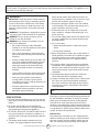
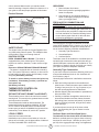
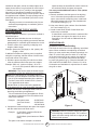
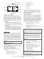
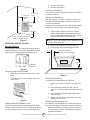
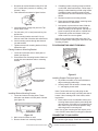
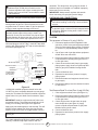
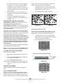
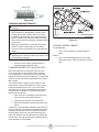
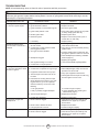
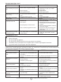
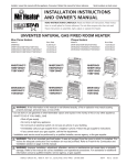
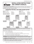
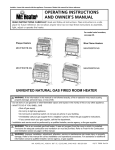
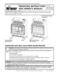
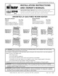
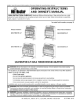
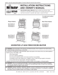
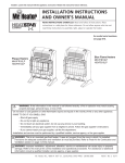
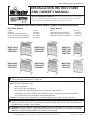
Operational Instructions Only - No Parts List INSTALLATION Instructions and Owner’s Manual READ INSTRUCTIONS CAREFULLY: Read and follow all instructions. Place instructions in a safe place for future reference. Do not allow anyone who has not read these instructions to assemble, light, adjust or operate the heater. UNVENTED NATURAL GAS FIRED ROOM HEATER Blue Flame Heaters Plaque Heaters Model # Burn Rate Model # Burn Rate MHBF6NG MHBF10NG/HSBF10NG/TSBF10NG MHBF20NGT/HSBF20NGT/TSBF20NGT MHBF30NGT/HSBF30NGT/TSBF30NGT 6,000 Btu/hr 10,000 Btu/hr 20,000 Btu/hr 30,000 Btu/hr MHIR10NG/HSIR10NG/TSIR10NG MHIR20NGT/HSIR20NGT/TSIR20NGT MHIR30NGT/HSIR30NGT/TSIR30NGT 10,000 Btu/hr 20,000 Btu/hr 30,000 Btu/hr MHBF30NGT/ HSBF30NGT/ TSBF30NGT MHBF20NGT/ HSBF20NGT/ TSBF20NGT MHBF6NG/ MHBF10NG/ HSBF10NG/ TSBF10NG MHIR30NGT/ HSIR30NGT/ TSIR30NGT MHIR20NGT/ HSIR20NGT/ TSIR20NGT MHIR10NG/ HSIR10NG/ TSIR10NG WARNING: If the information in this manual is not followed exactly, a fire or explosion may result causing property damage, personal injury, or loss of life. - Do not store or use gasoline or other flammable vapors and liquids in the vicinity of this or any other appliance. - WHAT TO DO IF YOU SMELL GAS • Shut off gas supply • Do not try to light any appliance • Do not touch an electrical switch; do not use any phone in your building. • Immediately call your gas supplier from a neighbor’s phone. Follow the gas supplier’s instructions. • If you cannot reach your gas supplier, call the fire department. - Installation and service must be performed by a qualified installer, service agency, or the gas supplier. WARNING: This is an unvented gas-fired heater. It uses air (oxygen) from the room in which it is installed. Provisions for adequate combustion and ventilation air must be provided. Refer to Fresh Air for Combustion and Ventilation section on page 3 of this manual. WARNING: Improper installation, adjustment, alteration, service or maintenance can cause injury or property damage. Refer to this manual for correct installation and operational procedures. For assistance or additional information consult a qualified installer, service agency, or gas supplier. Unvented Natural GasTHFired Heater OHIO Installation Instructions and Owner’s Manual 70574 1 44135 ENERCO GROUP, INC., 4560 W. 160 ST., Room CLEVELAND, · 216-916-3000 Rev.F 04/08 This appliance may be installed in an aftermarket* permanently manufactured (mobile) home, where not prohibited by local codes.This appliance is only for use with the type of gas indicated on the rating plate. This appliance is not convertible for use with any other gas. *Aftermarket completion of sale, not for the purpose of resale, from the manufacturer. WARNINGS safety shutoff system shuts down the heater if not enough fresh air is available. See Fresh Air for Combustion and Ventilation, pages 3 through 5. 5.Keep all air openings in heater clear, free of debris or any blockage. This will insure that enough air for proper combustion enters the heater. 6.If heater shuts off, do not relight until you provide fresh, outside air. If heater keeps shutting off, it requires servicing. 7.Turn off and unplug heater and let cool before servicing. Only a qualified service person should service and repair heater. 8.Do not run heater: IMPORTANT: Read this owner’s manual carefully and completely before trying to assembly, operate, or service this heater. Improper use of this heater can cause serious injury or death from burns, fire, explosion, electrical shock, and carbon monoxide poisoning. WARNING: This appliance is equipped for (natural or propane) gas. Field conversion is not permited. WARNING: Do not use any accessory not approved for use with this heater. WARNING: Any change to this heater or its controls can be dangerous. • Do not place clothing or other flammable material on or near the appliance. Never place any objects on the heater. • Where flammable liquids or vapors are used or stored • During dusty conditions. 9.Before using furniture polish, wax, carpet cleaner or similar products, turn heater off. If heated the vapors from these products may create a white powder residue within burner box or on adjacent walls or furniture. 10.Do not use heater if any part has been underwater. Immediately call a qualified service technician to inspect the room heater and to replace any part of the control system and any gas control which has been underwater. 11.Operating heater above elevations of 4,500 feet could cause pilot/ODS to shutdown heater. 12.Always run heater with control knob in a locked position. Never set control knob between locked positions. Poor combustion and higher levels of carbon monoxide may result if control knob is left between locked positions. DANGER: Carbon monoxide poisoning may lead to death. • Due to high temperatures, heater should be kept out of traffic and away from furniture and draperies. • Surface of heater becomes very hot when running. Keep children and adults away from hot surfaces to avoid burns or clothing ignition. Heater will remain hot for a time after shutdown. Allow heater surfaces to cool before handling. • Young children should be carefully supervised when they are in the same room with heater. • Make sure grille guard is in place before running heater. If screen or grille guard is removed for servicing it must be replaced prior to operating the heater. • Keep the appliance area clear and free from combustible materials, gasoline, and other flammable vapors and liquids. Carbon Monoxide Poisoning: PRECAUTIONS: Early signs of carbon monoxide poisoning resemble the flu, with headaches, dizziness, or nausea. If you have these signs, the heater may not be working properly. Get fresh air at once! Have heater serviced. Some people are more affected by carbon monoxide than others. These include pregnant women, persons with heart or lung disease or anemia, those under the influence of alcohol, and those at high altitudes. 1.BF-6 NG may be installed in any room, but not any place where a strong wind would shut down the appliance. 2. BF-10 NG and IR-10NG may be installed in a bedroom, but not a bathroom, or any place where a strong wind would shut down the appliance. 3.BF-20 NGT, BF-30 NGT, IR-20 NGT and IR-30 NGT may not be installed in a bedroom or bathroom, or any place where a strong wind would shut down the appliance. 4.This heater needs outside ventilation air to run properly. The Oxygen Depletion Sensor (ODS) Unvented Natural Gas Fired Room Heater Natural Gas: Raw natural gas is odorless. An odor making agent is added to natural gas, which helps you detect a natural gas leak. However the odor added to natural gas can fade. So natural gas may be present even though no 2 Installation Instructions and Owner’s Manual UNPACKING odor is detected. Make certain you read and understand all warnings. Keep this manual for reference. It is your guide to safe and proper operation of this heater. 1. Remove heater from carton. 2. Remove all protective packaging applied to heater for shipment. 3. Check heater for any shipping damage. If heater is damaged, promptly inform dealer where you bought heater. Product Features Fan Blower Switch Ignitor Button Room Temperature Thermometer LED FRESH AIR FOR COMBUSTION AND VENTILATION Control Knob Burners WARNING: This heater shall not be installed in a confined space or unusually tight construction unless provisions are provided for adequate combustion and ventilation air. Read the following instructions to insure proper fresh air for this and other fuel-burning appliances in your home. Grill Heater Cabinet Front Panel ESTABLISHING ADEQUATE VENTILATION The following are excerpts from National Fuel Gas Code, NFPA 54/ ANSI Z223.1, Section 5.3, Air for Combustion and Ventilation. All spaces in homes fall into one of the three following ventilation classifications: 1. Unusually Tight Construction 2. Unconfined Space 3. Confined Space This heater must not be installed in a confined space or unusually tight construction unless provisions are provided for adequate combustion and ventilation air. The information on pages 3 through 5 will help you classify your space and provide adequate ventilation. Figure 1 SAFETY DEVICE This heater has a pilot with an Oxygen Depletion Sensor (ODS) safety shut off system. The ODS/pilot shuts off the heater if there is not enough fresh air. IGNITION SYSTEM PIEZO: BF6NG/BF10NG / IR10NG – The heater is equipped with a piezo manual ignitor. This system requires no matches, batteries, or other source to light heater. Electronic: BF20NGT/BF30NGT/IR20NGT/IR30NGT – The heater is equipped with an electronic manual ignitor. This system requires no matches, or other source to light heater, but does require one AA battery to operate ignitor.(AA Battery included). Unusually Tight Construction These heaters have a control valve with a thermostat sensing bulb. This results in the greatest heater comfort and may result in lower bills. These heaters also include an electrical blower. The blower switch has three positions: MANUAL, OFF and AUTO. In AUTO, the blower will turn on and off as the heater cycles on and off. On MANUAL, the blower will run continuously. To turn blower off, use the OFF position. If your home meets all of the three following criteria you must provide additional fresh air. See Ventilation Air from Outdoors, page 5. Unusually tight construction is defined as construction where: a.Walls and ceilings exposed to the outside atmosphere have a continuous water vapor retarder with a rating of one perm (6 x 10-11 kg per pa-sec-m2) or less with openings gasketed or sealed and b.Whether stripping has been added on openable windows and doors, and c. Caulking or sealants are applied to areas such as joints around windows and door frames, between wall-ceiling joints, between wall panels, at penetrations for plumbing, electrical, and gas lines, and at other openings. If you home does not meet all of the three criteria above, see Determing the Type of Heater Location Space, page 4. LOCAL CODES Confined Space and Unconfined Space To install or replace battery unscrew the ignitor cap (red button), insert battery positive (+) terminal up and replace cap. (AA Battery included) THERMOSTATIC CONTROL ON THERMOSTAT MODELS (BF20NGT, BF30NGT, IR20NGT and IR30NGT) Install and use heater with care. Installation must conform to local codes or in the absences of local codes, use the latest edition of National Fuel Gas Code ANSI Z223.1/NFPA 54. Unvented Natural Gas Fired Room Heater The National Fuel Gas Code, NFPA 54/ ANSI Z223.1 defines a confined space as a space whose volume is less than 50 cubic feet per 1,000 Btu per hour (4.8 m3 per kW) of the aggregate input rating of all appliances 3 Installation Instructions and Owner’s Manual installed in that space, and an unconfined space as a space whose volume is not less than 50 cubic feet per 1,000 Btu per hour (4.8 m3 per kW) of the aggregate input rating of all appliances installed in that space. Rooms communicating directly with the space in which the appliances are installed*, through openings not furnished with doors, are considered a part of the unconfined space. *Adjoining rooms are communication only if there are doorless passageways or ventilation grills between them. space because the actual Btu/hr used is more than the maximum Btu/hr the space can support. You must provide additional fresh air. Your options are as follows: A.Rework worksheet, and the space of an adjoining room. If the extra space provides an unconfined space, remove door to adjoining room or add ventilation grills between the rooms. See Ventilation Air From Inside Building (Fig. 2). B.Vent room directly to the outdoors. See Ventilation Air From Outdoors (Fig. 3). C.Install a lower Btu/hr heater if lower Btu/hr size makes room unconfined. If actual Btu/hr used is less than the maximum Btu/ hr the space can support, the space is an unconfined space. You will need no additional fresh air ventilation. DETERMINING THE TYPE OF HEATER LOCATION SPACE: Use this method to determine if you have a confined or unconfined space. Note: the space includes the room in which you install heater plus any adjoining rooms with doorless passageways or ventilation grills between the rooms. 1.Find the volume of the space by multiplying room length x width x height. Example: Space size 18ft (length) x 18ft. (width) x 8ft. (height) = 2592 If additional ventilation to adjoining room is supplied with grills or openings, add the volume of these rooms to the total volume of the space. 2.Divide the space volume by 50 cubic feet to determine the maximum Btu/hr the space can support. Example: 2592 cu.ft. (volume of space) / 50 cu.ft. = 51.8 or 51,800 (maximum Btu/hr the space can support) WARNING: If the area in which the heater may be operated is smaller than defined as an unconfined space or if the building is of unusually tight construction, provide adequate combustion and ventilation air by the methods described in the National Fuel Gas Code, NFPA 54/ ANSI Z223.1, Section 5.3 or applicable local codes. 3.Add the Btu/hr of all the fuel-burning appliances in the space such as, Vent–free heater, Gas water heater, Gas furnace, Vented gas heater, Gas fireplace logs, and Other gas appliances* *Do not include direct-vent gas appliances. Directvent draws combustion air from the outdoors and vents to the outdoors. Example: Gas water heater 40,000 Btu/hr Vent Free Heater + 20,000 Btu/hr Total =60,000 Btu/hr 4.Compare the maximum Btu/hr the space can support with the actual amount of Btu/hr used. Example: 51,800 Btu/hr (maximum Btu/hr the space can support) 60,000 Btu/hr (Actual amount of Btu/hr used) The space in the above example is a confined Unvented Natural Gas Fired Room Heater VENTILATION AIR Ventilation from Inside Building This fresh air would come from an adjoining unconfined space. When ventilation to an adjoining unconfined space, you must provide two permanent openings: one within 12” of the ceiling and one within 12” of the floor on the wall connecting the two spaces (see options 1 & 2 of fig. 2). You can also remove door into adjoining room (see option3, fig 2). Follow the National Fuel Gas Code NFPA 54/ ANSI Z223.1, Section 5.3, Air for Combustion and Ventilation for required size of ventilation grills or ducts. 12” Ventilation Gills into Adjoining Room Option 1 Or remove door into Adjoining Room Option 3 Ventilation Gills into Adjoining Room - Option 2 12” Figure 2. WARNING: Rework worksheet, adding the space of the adjoining unconfined space. The combined space must have enough fresh air to supply all appliance in both spaces. 4 Installation Instructions and Owner’s Manual • • • • • VENTILATION AIR OUTLET AIR VENTILATED ATTIC OUTLET AIR TO ATTIC TO CRAWL SPACE INLET AIR Test gauge connection* Sediment trap Tee joint Pipe wrench *A CSA/AGA certified equipment shutoff valve with 1/8” NPT tap is an acceptable alternative to test gauge connection. Purchase a CSA/AGA certified equipment shutoff valve from your dealer. VENTILATION CRAWL SPACE Figure 3. LOCATING HEATER Ventilation from Outdoors This heater is designed to be mounted on the wall. The heater can also be located on a non-combustible floor, away from a wall by using the floor mounting stands included with the heater. If installed on combustible flooring such as carpeting, tile or other combustible material other than wood flooring, the heater must be placed on a wood panel the full width and depth of the appliance. For convenience and efficiency, install the heater: If necessary provide extra fresh air by using ventilation grills or ducts. Connect these items directly to the outdoors or spaces open to the outdoors. These include attics* and crawl spaces. Follow the National Fuel Gas Code NFPA 54/ ANSI Z223.1, Section 5.3, Air for Combustion and Ventilation for required size of ventilation grills or ducts. *IMPORTANT: Do not provide openings for inlet or outlet into attic. If attic has a thermostat-controlled power vent, heated air entering the attic will activate the power vent. IMPORTANT: Vent-free heaters add moisture to the air. Although this is beneficial, installing heater in rooms without enough ventilation air may cause mildew to form from too much moisture. See Fresh Air for Combustion and Ventilation, pages 3 through 5. • Where there is easy access for operation, inspection, and service • In the coldest part of the room. • If planning to use fan, locate heater near an electrical outlet. CAUTION: If you install the heater in a home garage: Heater pilot and burner must be at least 18 inches above floor. Locate heater where moving vehicle will not hit it. CAUTION: This heater creates warm air currents. These currents move heat to wall surfaces next to heater. Installing heater next to vinyl or cloth wall covering or operating heater where impurities (such as tobacco smoke, aromatic candles, cleaning fluids, oil or kerosene lamps, etc.) are present in the air may discolor walls. WARNING: Never install the heater: • In a bathroom; except MHBF6NG • In a bedroom (IR20NGT, IR30NGT, BF20NGT or BF30NGT) • In a recreational vehicle·. INSTALLATION NOTICE: This heater is intended for the use as supplemental heat. Use this heater along with your primary heating system. Do not install this heater as your primary heat source. If you have a central heating system, you may run system’s circulating blower while using heater. This will help circulate the heat throughout the house. In the event of a power outage, you can use this heater as your primary heat source for the duration of the outage. WARNING: A qualified service person must install heater. Follow all local codes. CHECK GAS TYPE Use only natural gas. If your gas supply is not natural gas, do not install heater. Call dealer where you bought heater for proper type heater. • Where curtains, furniture, clothing, or other flammable objects are less than 36 inches from the front, top, or sides of the heater. • As a fireplace insert • In high-traffic areas • In windy or drafty areas WARNING: Heater must be mounted to maintain the minimum clearances shown in Figure 4. If possible, provide greater clearances from the floor, ceiling, and joining walls. THIS INSTALLATION REQUIRES: Before installing heater, make sure you have the items listed below: • Piping (check local codes) • Sealant (resistant to natural gas) • Equipment shutoff valve* Unvented Natural Gas Fired Room Heater Ground joint union 5 Installation Instructions and Owner’s Manual 1. Attach to wall studs 2. Attach to wall anchor Attaching to Wall Stud: 6” Min from adjoining walls Left Side This way is the best providing the strongest mounting in wood frame houses. 36” min. from ceiling Attaching to Wall Anchor: This way allows you to attach mounting bracket to hollow walls (wall areas between studs) or to solid walls (concrete or masonry). Decide which way best suits your needs. Either method will provide a secure hold for the mounting bracket. Right Side 1. Tape mounting bracket to wall where heater will be located. Make sure mounting bracket is level. For wall stud mounting locate one end of the mounting bracket over a wall stud. WARNING: Maintain minimum clearances shown in figure 7. If you can, provide greater clearances from the floor and joining wall. 2. Mark screw locations on wall (see figure 7). 3. Remove tape and mount bracket from wall. Floor 2” min. to top surface of carpet, tile or other combustible material Figure 4 FASTENING HEATER TO WALL Mounting Bracket The mounting bracket in located on the back panel of heater (see figure 5). It has been taped there for shipping. Remove mounting bracket from back panel. Adjoining Wall 6-1/2” Min. 10,000 BTU 10-1/4” min 20,000-30,000 BTU Mounting Bracket 16” (Lg) 12-9/64” (Sm) 17-1/2” Min. Mark mounting hole locations and drill holes where indicated. Allow for minimum clearances Figure 5 Removing Front Panel of Heater 1. Remove three screws on bottom front of front panel. 2. Pull bottom of front panel forward, then down (see figure 6) Figure 7 Attaching to Wall Stud: For attaching mounting bracket to wall studs 1. Drill holes at marked locations using 9/64” drill bit. 2. Place mounting bracket onto wall. Line up holes on each end of bracket with hole drilled in wall. 3. Insert mounting screws through bracket and into wall studs. 4. Tighten screws until mounting bracket is firmly fastened to wall studs. Figure 6 Attaching to Wall using Anchor: Attaching Mounting Bracket to Wall For attaching mounting bracket to hollow walls (wall areas between studs) or solid walls (concrete or masonry) Note: Wall anchors, mounting screws, and spacer are in hardware package. The hardware package is provided with heater. Use holes on each end of mounting bracket to attach bracket to wall. These holes are 16 inches apart. Attach mounting bracket to wall in one of two following ways. Unvented Natural Gas Fired Room Heater 6 Installation Instructions and Owner’s Manual 1. Drill holes at marked locations using 5/16” drill bit. For solid walls (concrete or masonry), drill at least 1” deep. 2. Fold wall anchor as shown in figure 8 below. 4. If installing bottom mounting screw into hollow or solid wall, install wall anchors. Follow steps 1 through 4 under Attaching to Wall using Anchor. If installing bottom mounting screw into wall stud, drill holes at marked locations using 9/64” drill bit. 5. Re-place heater onto mounting bracket. 6. Place spacers between bottom mounting holes and wall anchor or drilled hole. 7. Hold spacer in place with one hand. With the other hand, insert mounting screw through bottom mounting hole and spacer. Place tip of screw in opening of wall anchor or drilled hole. 8. Tighten both screws until heater is firmly secured to wall. Do not over tighten. Note: Do not re-place front panel at this time. Replace front panel after making gas connections and checking for leaks. Figure 8. 3. Insert wall anchor (wings first) into hole. Tap anchor flush to wall. 4. For thin walls (1/2” or less) insert red key into wall anchor. 5. Place mounting bracket onto wall. Line up holes on each end of bracket with wall anchors. 6. Insert mounting screws through bracket and into wall anchors. 7. Tighten screws until mounting bracket is firmly fastened to wall. FLOOR MOUNTING AWAY FROM WALL: Placing Heater on Mounting Bracket 1. Locate two horizontal slots on back pane of heater (see figure 9). 2. Place heater onto mounting bracket. Slide horizontal slots onto stand-out tabs on mounting bracket. Horizontal Slots Figure 11 Installing Support Feet (see figure 11) 1. Lay heater onto table on its back with bottom edge overhanging table edge. 2. Securely attach feet to bottom of heater using 2 – self-tapping screws each. Mounting Bracket mounted to wall Figure 9. Note: Feet should have long end going out the front of heater, and the edge coinciding with side of heater. If feet overhang side of the heater, switch leg location. 3. Place heater on non-combustible surface (see Locating Heater above) before proceeding with gas connection. If this will be a permanent location, heater may be locked into position using anchoring holes in mounting feet. Note: Use of floor mounting feet will require you to use a 3/8 NPT street elbow to make gas connection. Installing Bottom Mounting Screws 1. Locate two bottom mounting holes. These holes are near bottom on back panel of heater (see figure 10). Figure 10 CONNECTING TO GAS SUPPLY 2. Mark screws locations on wall. 3. Remove heater from mounting bracket. Unvented Natural Gas Fired Room Heater WARNING: A qualified service person must connect heater to gas supply. Follow all local codes. 7 Installation Instructions and Owner’s Manual WARNING: This appliance requires a 3/8” NPT (National Pipe Thread) inlet connection to the pressure regulator. Use of floor mounting feet will require you to use a 3/8 NPT street elbow to make gas connection. CAUTION: Never connect heater to private (non-utility) gas well. This gas is commonly known as well-head gas. IMPORTANT: Check your gas line pressure before connecting heater to gas line. Gas line pressure must be no greater than 14 inches of water. If gas line pressure is higher, heater regulator damage could occur. CAUTION: Use only new black iron or steel pipe. Internally-tinned copper tubing may be used in certain areas. Check your local codes. Use pipe of larger enough diameter to allow proper gas volume to heater. If pipe is too small, undue loss of pressure will occur. taminants. This keeps them from going into heater. If sediment trap is not installed or is installed improperly, heater may not run correctly. IMPORTANT: Hold pressure regulator with wrench when connecting it to gas piping and/or fittings. CHECKING GAS CONNECTIONS WARNING: Test all gas piping and connections for leaks after installing or servicing. Correct all leaks at once. WARNING: Never use an open flame to check for a gas leak. Apply a mixture of liquid soap and water to all joints. Bubbles forming show a leak. Correct all leaks at once. PRESSURE TESTING GAS SUPPLY PIPING SYSTEM Test pressure in Excess of ½ psig (3.5kPa) Installation must include an equipment shutoff valve, union and plugged 1/8” NPT tap. Locate NPT tap within reach of test gauge hookup. NPT tap must be upstream from heater (see figure 12). 1. Disconnect appliance with its appliance main gas valve (control valve) and equipment shutoff valve from gas supply piping system. Pressures in excess of ½ psig will damage heater regulator. 2. Cap off open end of gas pipe where equipment shutoff valve was connected. 3. Pressurize supply piping system by either using compressed air or opening main gas valve on or near gas meter. 4. Check all connections and joints in gas supply piping system. Apply mixture of liquid soap and water to gas joints. Bubbles forming show a leak. 5. Correct all leaks at once. 6. Depressurize and relieve pressure in supply piping system. 7. Reconnect heater and equipment shutoff valve to gas supply. 8. Reconnected fittings must be checked for leaks in next section. Pressure Regulator 3/8” NPT Pipe Nipple Heater Cabinet Ground Joint Union Test Gauge Connection Equipment Shutoff Valve Tee Joint Reducer Bushing to 1/8” NPT From Gas Meter (4” W.C. to 10.5” W.C. Pressure) 1/8” NPT Plug Tap Tee Joint Pipe Nipple Sediment Trap Cap 3” Minimum Figure 12 *A CSA/AGA certified equipment shutoff valve with 1/8” NPT tap is an acceptable alternative to test gauge connection. Purchase the CSA/AGA certified equipment shutoff valve from your dealer. See Accessories, page 17. IMPORTANT: Install an equipment shutoff valve in an accessible location. The equipment shutoff valve is for turning on or shutting off the gas to the appliance. Apply pipe joint sealant lightly to male threads. This will prevent excess sealant from going into pipe. Excess sealant in pipe could result in clogged heater fuel train. CAUTION: Use pipe joint sealant that is resistant to natural gas. Install sediment trap in supply line as shown in figure 12. Locate sediment trap where it is within reach for cleaning. A sediment trap traps moisture and conUnvented Natural Gas Fired Room Heater Test Pressure Equal To or Less Than ½ psig (3.5 kPa) 1. Close equipment shutoff valve (see figure 13). 2. Pressurize supply piping system by either using compressed air or opening main gas valve on or near gas meter. 3. Check all joints from the gas meter to equipment shutoff valve (see figure 14). Apply mixture of liquid soap and water to gas joints. Bubbles forming show a leak. 4. Correct all leaks at once. 5. Depressurize and relieve pressure from supply piping system. 8 Installation Instructions and Owner’s Manual Pressure Testing Heater Gas Connections: ELECTRICAL WIRING DIAGRAM: 1. Make sure that the heater supply piping system is connected and has been leak tested as described above. 2. Make sure control knob of heater is in OFF position. 3. Open equipment shutoff valve (see figure 13). 4. Open main gas valve on or near gas meter. 5. Check all joints from equipment shutoff valve to control valve (see figure 14). Apply mixture of liquid soap and water to gas joints. Bubbles forming show a leak. 6. Correct all leaks at once. 7. Light heater (see Operating Your Heater, pages 11 and 12 for thermostat models or pages 9 and 10 for non-thermostat models). Check the rest of the internal joints for leaks. 8. Turn off heater (see To Turn OFF Gas to Appliance, page 12 for thermostat models and page 11 for non-thermostat models). 9. Replace lower front panel. Figure 15 If any original wiring as supplied with the heater must be replaced, it must be replaced with type AWG 105oC wire or its equivalent except as indicated. WARNING: Electrical Grounding Instructions: This heater is equipped with a three-prong (grounding) plug for your protection against shock hazard and should be plugged into a properly grounded threeprong receptacle. Open Equipment Shutoff Valve Closed OPERATING YOUR HEATER NON-THERMOSTAT MODELS IR10NG / BF6NG / BF10NG Figure 13 FOR YOUR SAFETY READ BEFORE LIGHTING Control Valve WARNING: If you do not follow these instructions exactly, a fire or explosion may result causing property damage, personal injury or loss of life. A. This appliance has a pilot that must be lighted by hand. When lighting the pilot, follow these instructions exactly. B. BEFORE LIGHTING smell all around the appliance area for gas. Be sure to smell next to the floor because some gas is heavier than air and will settle on the floor. Gas Meter Equipment Shutoff Valve WHAT TO DO IF YOU SMELL GAS • Do not try to light any appliance. • Do not touch any electrical switch; do not use any phone in your building. • Immediately call you gas supplier from a neighbor’s phone. Follow the gas supplier’s instructions. Figure 14 • If you can not reach your gas supplier, call the fire department. Unvented Natural Gas Fired Room Heater 9 Installation Instructions and Owner’s Manual FOR BF6NG and BF10NG: After flame is established (see Burner Flame Pattern, Page 12) on “HI”, adjust heat output by turning control knob to desired position (“LO” or “HI”). Do not operate heater between locked positions. C. Use only your hand to push in or turn the gas control knob. Never use tools. If knob will not push in or turn by hand, don’t try to repair it; call a qualified service technician or gas supplier. Force or attempted repair may result in a fire or explosion. D. Do not use this appliance if any part has been underwater. Immediately call a qualified service technician to inspect the appliance and to replace any part of the control system which has been underwater. Control Knob LIGHTING INSTRUCTIONS 1. STOP! Read the all safety information included with and on the side of heater. 2. Check that gas supply to heater is on. 3. Push in gas control knob and slightly turn clockwise to the OFF position (see figure 16). Note: Knob cannot be turned from PILOT to OFF unless knob is pushed in slightly. Do not force. 4. Wait five (5) minutes. Then smell for gas, including near the floor. If you smell gas, STOP! Follow “B” in the safety information above. If you do not smell gas, go to the next step. 5. Push in gas control knob slightly and turn counterclockwise to PILOT/IGN and depress for five (5) seconds. Note: The first time that the heater is operated after connecting the gas supply, the control knob should be depressed for about 30 seconds. This will allow air to bleed from the gas system. 6. Push in control knob and rotate control knob back to OFF position then rotate counterclockwise to PILOT/IGN position. This will light pilot. If needed gently keep rotating control knob back and forth while depressed until pilot lights. 7. Keep control knob depressed in for ten (10) seconds after lighting pilot. If pilot goes out, repeat steps 4, 5, 6 and 7. Figure 16 Figure 17 • If pilot does not stay lit, refer to Troubleshoot- Control Knob ing, pages 14 & 15. Also, contact a qualified service person or gas supplier for repairs. Burner tile pattern for IR only. • If control knob does not pop up when released, contact a qualified service person or gas supplier for repairs. 8. FOR IR10NG: When the pilot is lit, turn the control knob to “LO” position to light heater. Leave on “LO” position until first burner tile has turned bright red (Figure 18) FOR BF6NG and BF10NG: When the pilot is lit, turn the control knob to “HI” position to light heater. 9. FOR IR10NG: After first burner tile has turned bright red, adjust heat output by turning control knob to desired position (“LO” or “HI”). Do not operate heater between locked positions. Unvented Natural Gas Fired Room Heater LOW HIGH OFF Figure 18 CAUTION: Do not try to adjust heating level by using equipment shutoff valve. 10 Installation Instructions and Owner’s Manual place any part of the control system which has been underwater. WARNING: When running heater, set control knob at “LO” or “HI” locked positions. Poor combustion and higher levels of carbon monoxide may result if heater is operated with control knob positioned between locked positions. IMPORTANT: Release downward pressure while turning control knob. Control knob must be locked at the desired position. LIGHTING INSTRUCTIONS 1. STOP! Read the all safety information included with and on the side of heater. 2. Make sure the equipment shutoff valve is fully open. 3. Push in gas control knob and slightly turn clockwise to the OFF position (see figure 19). 4. Wait five (5) minutes. Then smell for gas including near the floor. If you smell gas, STOP! Follow “B” in the safety information above. If you do not smell gas, go to the next step. 5. Push in and turn control knob counterclockwise to PILOT. Press in control knob for five (5) seconds. Note: The first time that the heater is operated after connecting the gas supply, the control knob should be depressed for about 30 seconds. This will allow air to bleed from the gas system. This may take longer in some installations TO TURN OFF GAS TO APPLIANCE SHUTTING OFF HEATER: 1. Turn control knob clockwise to the OFF position. 2. Turn off all electrical power to the appliance if servicing is to be preformed. 3. Turn off equipment shutoff valve. SHUTTING OFF BURNER ONLY (PILOT STAYS LIT) 1. Turn control knob clockwise to the PILOT/IGN position. OPERATING YOUR HEATER THERMOSTAT MODELS Ignitor Button IR20NGT, IR30NGT, BF20NGT, BF30NGT, TSIR20NGT, TSIR-30NGT, BF20NGT, BF30NGT Control Knob FOR YOUR SAFETY READ BEFORE LIGHTING WARNING: If you do not follow these instructions exactly, a fire or explosion may result causing property damage, personal injury or loss of life. A. This appliance has a pilot which must be lighted by pushing the ignitor button. When lighting the pilot, follow these instructions exactly. B. BEFORE LIGHTING smell all around the appliance area for gas. Be sure to smell next to the floor because some gas is heavier than air and will settle on the floor. Figure 19. 6. With control knob pressed in, push down and release the ignition button. This will light pilot. If needed keep pressing igniter button until pilot lights. 7. Keep control knob pressed in for (30) seconds after lighting pilot. After 30 seconds, release control knob. WHAT TO DO IF YOU SMELL GAS • Do not try to light any appliance. • Do not touch any electrical switch; do not use any phone in your building. • Immediately call you gas supplier from a neighbor’s phone. Follow the gas supplier’s instructions. • If you can not reach your gas supplier, call the fire department. C. Use only your hand to push in or turn the gas control knob. Never use tools. If knob will not push in or turn by hand, don’t try to repair it call a qualified service technician or gas supplier. Force or attempted repair may result in a fire or explosion. D. Do not use this appliance if any part has been underwater. Immediately call a qualified service technician to inspect the appliance and to reUnvented Natural Gas Fired Room Heater Figure 20 11 Installation Instructions and Owner’s Manual • If pilot does not stay lit, refer to Troubleshoot- couple cools, the heater will shut down. If pilot flame pattern is incorrect, as shown in Figure 22: ing, pages 14 & 15. Also, contact a qualified service person of gas supplier for repairs. • Turn heater off (see To Turn OFF Gas to Ap- • If control knob does not pop up when released, pliance, page 11 for non-thermostat models or page 12 for thermostat models). contact a qualified service person or gas supplier for repairs. 8. When the pilot is lit, turn control knob counterclockwise to heating level. The main burner should light. 9. To select the desired heat level, turn the temperature setting knob counterclockwise to between 1 & 5. • See Troubleshooting, pages 14 and 15. THERMOSTAT CONTROL OPERATION FOR IR20NGT / IR30NGT: The thermostatic control used simply turns on and off the burner. FOR BF20NGT / BF30NGT: The thermostatic control used modulates the flame size as the temperature gets closer to set point, then it turns off the burner upon reaching temperature. The burner will cycle back on when room temperature drops below the set temperature. The control knob can be set to any heat level between 1 and 5. Selecting the HI setting will cause the burner to remain on. Note: The thermostat sensing bulb measures the temperature of air near the heater cabinet. This may not always agree with room temperature (depending on housing construction, insulation location, room size, open air temperature, etc.). Frequent use of your heater will let you determine your own comfort levels. The LED temperature indicator measures approximate room temperature around the heater. Note: The LED temperature indicator DOES NOT operate with or control the thermostat setting of the heater. Figure 21 Figure 22 BURNER FLAME PATTERN Figure 23 show a correct burner flame pattern. Figure 24 shows an incorrect burner flame pattern. If burner flame pattern is incorrect, as shown in Figure 24: • Turn heater off (see To Turn OFF Gas to Ap- pliance, page 11 for non-thermostat models or page 12 for thermostat models). • See Troubleshooting, pages 14 and 15. Figure 23a. TO TURN OFF GAS TO APPLIANCE SHUTTING OFF HEATER 1. Turn control knob clockwise to the OFF position. 2. Turn off all electrical power to the appliance if servicing is to be preformed. 3. Turn off equipment shutoff valve. SHUTTING OFF BURNER ONLY (PILOT STAYS LIT) 1. Turn control knob clockwise to the PILOT/IGN position. Figure 23b. INSPECTING BURNER Check pilot flame pattern and burner flame pattern often. PILOT FLAME PATTERN Figure 21 show a correct pilot flame pattern. Figure 22 shows an incorrect pilot flame pattern. The incorrect pilot flame pattern is not touching thermocouple. This will cause the thermocouple to cool. When the thermoUnvented Natural Gas Fired Room Heater Figure 24a. 12 Installation Instructions and Owner’s Manual Figure 24b CLEANING AND MAINTENANCE WARNING: Turn off heater and let cool before servicing. CAUTION: You must keep control areas, burner and circulation air passageways of heater clean. Inspect these areas of heater before use. Have the heater inspected yearly by a qualified service person. Heater may need more frequent cleaning due to excess lent from carpeting, bedding material, pet hair, etc. Make sure grille guard is in place before running heater. If screen or grille guard is removed for servicing it must be replaced prior to operating the heater. WARNING: Failure to keep the primary air opening(s) of the burner(s) clean may result in sooting and property damage. Figure 25 CLEANING HEATER CABINET Air passageways • Use a vacuum cleaner or pressurized air to clean Exterior • Use a soft cloth dampened with a mild soap and water mixture. Wipe the cabinet to remove dust. CLEANING ODS/PILOT AND BURNER • Use as vacuum cleaner, pressurized air or small soft bristled brush to clean. CLEANING BURNER PILOT AIR HOLE INLET We recommend that you clean the unit ever 2,500 hours of operation or every three months. We also recommend that you keep the burner tube and pilot assembly clean and free of dust and dirt. To clean these parts we recommend using compressed air no greater than 30 psig. This can be done by using a vacuum cleaner in the blow position, using compressed air in a can, please follow the directions on the can. If you don’t follow directions on the can you could damage the burner or pilot assembly. In addition, the directions that follow should also be followed. 1. Shut off the unit, including the pilot. Allow the unit to cool for at least thirty minutes. 2. Inspect burner and pilot for dust and dirt. 3. Blow air through the port/slots and holes in the burner. A yellow tip on the pilot flame indicates dust and dirt in the pilot assembly. To clean the pilot assembly find the small pilot air inlet hole about two inches from where the pilot flame comes out of the pilot assembly (see figure 25). With the unit off, lightly blow air through the air inlet hole. You may blow through a drinking straw if compressed air is not available. Unvented Natural Gas Fired Room Heater 13 Installation Instructions and Owner’s Manual TROUBLESHOOTING NOTE: All troubleshooting items are listed in order of operation and likely occurrence. WARNING: Only a qualified service person should service and repair heater. CAUTION: Never use a wire needle, or similar object to clean ODS/pilot. This can damage ODS/pilot unit. Make sure grille guard is in place before running heater. If screen or grille guard is removed for servicing it must be replaced prior to operating the heater. OBSERVED SYMPTOM When ignitor button is pressed in, there is no spark at pilot ODS/pilot lights but flame goes out when control knob is released POSSIBLE CAUSE 1. Ignitor electrode positioned wrong. 1. Reposition electrode 2. ignitor electrode is broken. 2. Replace electrode 3. Ignitor electrode not connected to ignitor. 3. Reconnect ignitor cable 4. Ignitor cable pinched or wet. 4. Free ignitor cable if pinched by any metal or tubing. Keep ignitor cable dry. 5. Broken ignitor cable. 5. Replace ignitor cable 6. Bad Piezo ignitor. 6. Replace control valve (Piezo is part of control valve on 10K units). 7. Low Battery. 7. Replace battery 1. Gas supply turned off or equipment shutoff valve closed. 1. Turn on gas supply turn off or open equipment shutoff valve closed 2. Control knob not fully pressed in while pressing ignition button. 2. Fully press in control knob while pressing ignition button 3. Air in gas line when installed. 3. Continue holding down control knob. Repeat ignition operation until air is removed. 4. Clean ODS/pilot (see Cleaning and Maintenance page 13). 4. ODS/pilot is clogged. 5. Gas regulator setting is not correct 6. Control knob not in pilot position When ignitor button is pressed in, there is a spark at the ODS/ pilot but no ignition 1. Control knob not fully pressed in. 2. Control knob not pressed in long enough 3. Equipment shutoff valve not fully open 4. Thermocouple connection loose at control valve 5. Pilot flame not touching thermocouple, which allows thermocouple to cool, causing pilot flame to go out. This problem could be caused by one or both of the following: a. Low gas pressure b. Dirty or partially clogged ODS/pilot Burner does not light after ODS/pilot is lit Delayed ignition of burner REMEDY 5. Replace gas regulator 6. Turn Control knob to pilot position 1. Press in control knob fully 2. After ODS/pilot lights, keep control knob pressed in for 30 seconds 3. Fully open equipment shutoff valve 4. Hand tighten thermocouple nut until snug, and then tighten 1/4 turn more. 5. - a. Contact local gas company b. Clean ODS/pilot (see Cleaning and Maintenance, page ?). 6. Thermocouple damaged 6. Replace thermocouple 7. Control valve damaged 7. Replace Control valve. 1. Burner orifice is clogged 1. Clean burner orifice (see Cleaning and Maintenance on page 13), or replace burner orifice 2. Burner orifice diameter to small 2. Replace burner orifice 3. Inlet gas pressure is too low 3. Contact local gas company 1. Manifold pressure is too low 1. Contact local gas company 2. Burner orifice is clogged 2. Clean burner orifice (see Cleaning and Maintenance on page 13), or replace burner orifice Unvented Natural Gas Fired Room Heater 14 Installation Instructions and Owner’s Manual TROUBLESHOOTING CON’T OBSERVED SYMPTOM Burner backfiring during operation Burner plaque(s) does not glow [Infrared Only] Slight smoke or odor during initial operation Heater produces a whistling noise when burner is lit POSSIBLE CAUSE 1. Burner orifice is clogged or damaged 2. Burner damaged 3. Gas regulator defective 1. Plaque damaged 2. Control knob set between locked positions. 3. Inlet gas pressure is too low 1. Residues from manufacturing process 1. Turning control knob to HI position when burner is cold 2. Air in gas line 3. Air passageways on heater blocked 4. Dirty or partially clogged burner orifice. White powder residue forming within burner box or on adjacent walls or furniture 1. When heated, vapors from furniture polish, wax, carpet cleaners, etc., turn into white powder residue REMEDY 1. Clean burner orifice (see Cleaning and Maintenance on page 13), or replace burner orifice 2. Replace burner 3. Replace gas regulator 1. Replace burner 2. Turn control knob until it locks at desired setting. 3. Replace gas regulator 1. Problem will stop after a few hours of operation 1. Turn control knob to LO position and let warm up for a minute. 2. Operate burner until air is removed from line have gas line checked by local gas company. 3. Observe minimum installation clearances (see Figure 4 page6) 4. Clean burner orifice (see Cleaning and Maintenance on page 13), or replace burner orifice. 1. Turn heater off when using furniture polish, wax, carpet cleaner or similar products. TROUBLESHOOTING WARNING: If you smell gas: • • • • • Shut off gas supply Do not try to light any appliance Do not touch any electrical switch; do not use any phone in your building Immediately call you gas supplier from a neighbor’s phone. Follow the gas supplier’s instructions. If you cannot reach your gas supplier, call the fire department. IMPORTANT: Operating heater where impurities in air exist may create odors. Cleaning supplies, paint, paint remover, cigarette smoke, cements and glues, new carpet or textiles, etc., create fumes. These fumes may mix with combustion air and create odors and possible discoloration of walls and ceilings. OBSERVED SYMPTOM Heater produces unwanted odors. Heater shuts off in use (ODS operates) Gas odor even when control knob is in OFF position Gas odor during combustion Heater produces a clicking/ticking noise just after burner is lit or shut off Moisture/condensation noticed on windows POSSIBLE CAUSE 1. Heater burning vapors from paint, hair spray, glues, etc. See IMPORTANT statement above 2. Gas leak. See WARNING statement at top of page. 1. Not enough fresh air is available 2. Low line pressure 3. ODS/pilot is partially clogged 1. Gas leak. See WARNING statement at top of page 2. Control valve is defective 1. Foreign matter between control valve and burner 2. Gas leak. See WARNING statement at top of page 1. Metal expanding while heating or contracting while cooling 1. Not enough combustion/ventilation air Unvented Natural Gas Fired Room Heater 15 REMEDY 1. Ventilate room. Stop using odor-causing products while heater is running. 2. Locate and correct all leaks (see Checking Gas Connections, page 8) 1. Open window and/or door for ventilation 2. Contact local gas company 3. Clean ODS/pilot (see Cleaning and Maintenance, page 13) 1. Locate and correct all leaks (see Checking Gas Connections, page 8) 2. Replace control valve 1. Take apart gas tubing and remove foreign matter 2. Locate and correct all leaks (see Checking Gas Connections, page 8) 1. This is common with most heaters. If noise is excessive, contact qualified service person 1. Refer to Fresh Air for Combustion and Ventilation page 3 through 5 Installation Instructions and Owner’s Manual SPECIFICATIONS IR10NG IR20NGT IR30NGT BTU (Available) 10,000 20,000 30,000 Type of Gas Natural Gas Only Natural Gas Only Natural Gas Only Ignition Piezo Battery ignitor (1-AA) Battery ignitor (1-AA) Pressure Regulator Setting 4.5 Inches of Water 4.5 Inches of Water 6.0 Inches of Water Inlet Gas Pressure (Maximum) 14 Inches of Water 14 Inches of Water 14 Inches of Water Inlet Gas Pressure (Minimum) 9 Inches of Water 9 Inches of Water 9 Inches of Water Electrical Rating/Blower — 120V, 60Hz, 1 120V, 60Hz, 1 Burners / Orifice nozzles 2 3 4 Thermostatic Control No Yes Yes Clearances: inches (mm) Top 36” (915cm) 36” (915cm) 36” (915cm) Sides 6” (152cm) 10.5” (267cm) 10.5” (267cm) Floor (min. to top of carpet) 2” (51cm) 2” (51cm) 2” (51cm) 36” (915cm) 36” (915cm) 36” (915cm) Fabric / flammable objects BF6NG BF10NG BF20NGTBF30NGT BTU (Available) 6,000 10,000 20,000 30,000 Type of Gas Natural Gas Only Natural Gas Only Natural Gas Only Ignition Piezo Battery ignitor (1-AA) Battery ignitor (1-AA) Pressure Regulator Setting 4.5 Inches of Water 4.5 Inches of Water 4.5 Inches of Water Inlet Gas Pressure (Maximum) 14 Inches of Water 14 Inches of Water 14 Inches of Water Inlet Gas Pressure (Minimum) 9 Inches of Water 9 Inches of Water 9 Inches of Water 120V, 60Hz, 1 120V, 60Hz, 1 Electrical Rating/Blower — Burners / Orifice nozzles 1 1 1 Thermostatic Control No Yes Yes Clearances: inches (mm) Top 36” (915cm) 36” (915cm) 36” (915cm) Sides 6” (152cm) 10.5” (267cm) 10.5” (267cm) Floor (min. to top of carpet) 2” (51cm) 2” (51cm) 2” (51cm) Fabric / flammable objects 36” (915cm) 36” (915cm) 36” (915cm) Unvented Natural Gas Fired Room Heater 16 Installation Instructions and Owner’s Manual Unvented Natural Gas Fired Room Heater 17 Installation Instructions and Owner’s Manual Unvented Natural Gas Fired Room Heater 18 Installation Instructions and Owner’s Manual Unvented Natural Gas Fired Room Heater 19 Installation Instructions and Owner’s Manual Unvented Natural Gas Fired Room Heater 20 Installation Instructions and Owner’s Manual Unvented Natural Gas Fired Room Heater 21 Installation Instructions and Owner’s Manual REPLACEMENT PARTS Note: use only original replacement parts. This will protect you warranty coverage for parts replaced under warranty. PARTS UNDER WARRANTY Contact authorized dealer from whom you purchased this product. If they are unable to supply original replacement part(s), call the number on back of manual. When contacting your dealer have ready: • • • • • • Your name Your address Model and serial numbers of your heater How heater was malfunctioning Type of gas used (Natural Gas) Purchase date Usually, we will ask you to return the defective part to the factory. PARTS NOT UNDER WARRANTY Contact authorized dealer of this product. If they can’t supply original replacement part(s), call Enerco Group, Inc.’s 800# on the back of this manual. TECHNICAL SERVICE You may have further questions about installation, operation, or troubleshooting, if so, contact Enerco Group, Inc.’s 800# on the back of this manual. ACCESSORIES Purchase these heater accessories from your local dealer. If they can not supply these accessories, contact your nearest Parts Central or call Enerco Group, Inc.’s 800# for information. You can also write to the address listed on the front page of this manual. Equipment Shutoff Valve Unvented Natural Gas Fired Room Heater 22 Installation Instructions and Owner’s Manual Notes Unvented Natural Gas Fired Room Heater 23 Installation Instructions and Owner’s Manual WARRANTY INFORMATION Model # Start Serial# MHBF6NG MHC-550050001001 MH/HS/TSBF10NG MHC-705100000539 Model ______________________ MH/HS/TSBF20NG MHC-705200002199 Serial No. ___________________ MH/HS/TSBF30NG MHC-705300004519 Date Purchased _______________ MH/HS/TSIR10NG MHC-705400001152 MH/HS/TSIR20NG MHC-705500002549 MH/HS/TSIR30NG MHC-705600003381 Keep this warranty Always specify model and serial numbers when communication with the factory. We reserve the right to amend these specifications at any time without notice. The only warranty applicable is our standard written warranty. We make no other warranty, expressed or implied. Enerco Group, Inc. warrants this product to be free from defects in materials and components for two (2) years from the date of first purchase, provided that the product has been properly installed, operated and maintained in accordance with all applicable instructions. To make a claim under this warranty the Bill of Sale or cancelled check must be presented. The warranty is extended only to the original retail purchaser. This warranty covers the cost of part(s) required to restore the heater to proper operating condition and an allowance for labor when provided by an Enerco Group, Inc. Authorized Service Center. Warranty part(s) MUST be obtained through authorized dealers of this product and/or Enerco Group, Inc. who will provide original factory replacement parts. Failure to use original factory parts voids this warranty. The heater MUST be installed by a qualified installer in accordance with all local codes and instructions furnished with the unit. This warranty does not apply to parts that are not in original condition because of normal wear and tear of parts that fail or become damaged as a result of misuse, accidents, lack of proper maintenance or defects caused by improper installation. Travel, diagnostic cost, labor, transportation and any and all such costs related to repairing a defective heater will be the responsibility of the owner. TO THE FULL EXTENT ALLOWED BY THE LAW OF THE JURISDICTION THAT GOVERNS THE SALE OF THE PRODUCT; THIS EXPRESS WARRANTY EXCLUDES ANY AND ALL OTHER EXPRESSED WARRANTIES AND LIMITS THE DURATION OF ANY AND ALL IMPLIED WARRANTIES OF MERCHANTABILITY AND FITNESS FOR A PARTICULAR PURPOSE, TO TWO (2) YEARS OF ALL COMPONENTS FROM THE FIRST DATE OF PURCHASE; AND ENERCO GROUP, INC.’S LIABILITY IS HEREBY LIMITED TO THE PURCHASE PRICE OF THE PRODUCT AND ENERCO GROUP, INC. SHALL NOT BE LIABLE FOR ANY OTHER DAMAGES WHATSOEVER INCLUDING INDIRECT, INCIDENTAL OR CONSEQUENTIAL DAMAGES. Some states do not allow a limitation on how long an implied warranty lasts or an exclusion or limitation on incidental or consequential damages, so the above limitation on implied warranties, or limitation on damages, may not apply to you. This warranty gives you specific legal rights, and you may also have other rights that very from state to state. Always specify model and serial number when communication with the factory. ENERCO GROUP, INC., 4560 W. 160TH ST., CLEVELAND, OHIO 44135 216-916-3000 Toll Free Number 1-800-251-0001 www.mrheater.com Mr. Heater is a registered trademarks of Enerco Group, Inc. ANSI Z21.11.2b-2004 © 2005, Enerco/Mr. Heater. All rights reserved Unvented Natural Gas Fired Room Heater 24 Installation Instructions and Owner’s Manual