1
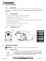
IS2300 Rev-A1 Max-Flo XL™ by Owner’s Manual Max-Flo XL Pump Series The Hayward Max-Flo XL is a series of high technology self-priming pumps that combine performance, dependability and value with durable construction. Designed for pools of all types and sizes, Max-Flo XL features 1 1/2” x 2” union connections to match a variety of plumbing configurations and a cam and ramp strainer cover that seals with less than a quarter turn. The Max-Flo XL is an ideal choice for both new construction or as a replacement pump. NOTE - To prevent potential injury and to avoid unnecessary service calls, read this manual carefully and completely. SAVE THIS INSTRUCTION MANUAL Hayward Pool Products 620 Division St, Elizabeth, NJ 07201 Phone: (908) 351-5400 www.haywardpool.com Table of Contents 1. 2. IMPORTANT SAFETY INSTRUCTIONS ...............................................................................................................3 General Information .................................................................................................................................... 6 2.1. Introduction 6 2.2. Primary Features 6 2.3. Product Dimensions 6 3. Installation and Wiring ................................................................................................................................ 6 3.1. Pump Location 6 3.2. Pump Mounting 7 3.3. Pipe Sizing Chart 7 3.4. Plumbing 7 3.5. Electrical 8 3.6. Electrical Specs 8 3.7. Voltage 8 3.8. Grounding and Bonding 8 3.9. Wiring 9 4. Startup & Operation ................................................................................................................................... 10 4.1. Prior to Start-Up 10 4.2. Starting/Priming the Pump 10 5. Maintenance.............................................................................................................................................. 11 6. Storage / Winterization .............................................................................................................................. 11 6.1. Storing Pump For Winterization 11 7. Shaft Seal Change Instructions ................................................................................................................... 12 7.1. Removing the Motor Assembly 12 7.2. Removing the Impeller 12 7.3. Removing the Ceramic Seat 12 7.4. Seal Installation 13 7.5. Replacing the Impeller and Diffuser 14 7.6. Replacing the Motor Assembly 14 8. Replacement Parts ..................................................................................................................................... 15 8.1. Parts Diagram 15 8.2. Parts Listing 15 9. Troubleshooting......................................................................................................................................... 16 9.1. General Problems 16 10. Warranty .................................................................................................................................................... 18 11. Product Registration................................................................................................................................... 19 Page 2 of 20 USE ONLY HAYWARD GENUINE REPLACEMENT PARTS Max-Flo XL Pump IS2300 Rev-A1 1. IMPORTANT SAFETY INSTRUCTIONS Before installing or servicing this electrical equipment, turn power supply OFF. Basic safety precautions should always be followed, including the following: Failure to follow instructions may result in injury. This is the safety-alert symbol. When you see this symbol on your pump or in this manual, look for one of the following signal words, and be alert to the potential for personal injury. WARNING warns about hazards that could cause serious personal injury, death or major property damage and if ignored presents a potential hazard. CAUTION warns about hazards that will or can cause minor or moderate personal injury and/or property damage and if ignored presents a potential hazard. It can also make consumers aware of actions that are unpredictable and unsafe. The NOTICE label indicates special instructions that are important but not related to hazards. WARNING – Read and follow all instructions in this owner’s manual and on the equipment. Failure to follow instructions can cause severe injury and/or death. WARNING – This product should be installed and serviced only by a qualified professional. CAUTION – All electrical wiring MUST be in conformance with all applicable local codes, regulations, and the National Electric Code (NEC). USE OF NON-HAYWARD REPLACEMENT PARTS VOIDS WARRANTY. ATTENTION INSTALLER - THIS MANUAL CONTAINS IMPORTANT INFORMATION ABOUT THE INSTALLATION, OPERATION, AND SAFE USE OF THIS PUMP THAT MUST BE FURNISHED TO THE END USER OF THIS PRODUCT. FAILURE TO READ AND FOLLOW ALL INSTRUCTIONS COULD RESULT IN SERIOUS INJURY. WARNING – To reduce risk of injury, do not permit children to use or climb on this product. Closely supervise children at all times. Components such as the filtration system, pumps, and heaters must be positioned to prevent children from using them as a means of access to the pool. CAUTION – This pump is intended for use on permanently installed swimming pools and may also be used with hot tubs and spas if so marked. Do NOT use with storable pools. A permanently installed pool is constructed in or on the ground or in a building such that it cannot be readily disassembled for storage. A storable pool is constructed so that it is capable of being readily disassembled for storage and reassembled to its original integrity. Though this product is designed for outdoor use, it is strongly advised to protect the electrical components from the weather. Select a well-drained area, one that will not flood when it rains. It requires free circulation of air for cooling. Do not install in a damp or non-ventilated location. If installed within an outer enclosure or beneath the skirt of a hot tub or spa, adequate ventilation and free circulation of air must be provided to prevent overheating of the motor. Page 3 of 20 USE ONLY HAYWARD GENUINE REPLACEMENT PARTS Max-Flo XL Pump IS2300 Rev-A1 WARNING – Pool and spa components (seals, gaskets, etc.) have a finite life. All components should be inspected frequently and replaced at least every ten years, or if found to be damaged, broken, cracked, missing, or not securely attached. WARNING – Risk of Electric Shock. All electrical wiring MUST be in conformance with applicable local codes, regulations, and the National Electric Code (NEC). Hazardous voltage can shock, burn, and cause death or serious property damage. To reduce the risk of electric shock, do NOT use an extension cord to connect unit to electric supply. Provide a properly located electrical receptacle. Before working on pump or motor, turn off power supply to the pump. WARNING – To reduce the risk of electric shock replace damaged wiring immediately. Locate conduit to prevent abuse from lawn mowers, hedge trimmers and other equipment. WARNING – Risk of Electric Shock. In accordance with the National Electric Code (NEC), connect only to a branch circuit protected by a ground-fault circuit-interrupter (GFCI). Contact a qualified electrician if you cannot verify that the circuit is protected by a GFCI. The unit must be connected only to a supply circuit that is protected by a ground-fault circuit-interrupter (GFCI). Such a GFCI should be provided by the installer and should be tested on a routine basis. To test the GFCI, push the test circuit button. The GFCI should interrupt power. Push the reset button. Power should be restored. If the GFCI fails to operate in this manner, the GFCI is defective. If the GFCI interrupts power to the pump without the test button being pushed, a ground current is flowing, indicating the possibility of an electric shock. Do not use this pump. Disconnect the pump and have the problem corrected by a qualified service representative before using. WARNING – Failure to bond pump to pool structure will increase risk for electrocution and could result in injury or death. To reduce the risk of electric shock, see installation instructions and consult a professional electrician on how to bond pump. Also, contact a licensed electrician for information on local electrical codes for bonding requirements. Notes to electrician: Use a solid copper conductor, size 8 or larger. Run a continuous wire from external bonding lug to reinforcing rod or mesh. Connect a No. 8 AWG (8.4 mm2) [No. 6 AWG (13.3 mm2) for Canada] solid copper bonding wire to the pressure wire connector provided on the pump housing and to all metal parts of swimming pool, spa, or hot tub, and to all electrical equipment, metal piping (except gas piping), and conduit within 5 ft. (1.5 m) of inside walls of swimming pool, spa, or hot tub. IMPORTANT - Reference NEC codes for all wiring standards including, but not limited to, grounding, bonding and other general wiring procedures. WARNING – Suction Entrapment Hazard. Suction in suction outlets and/or suction outlet covers, which are damaged, broken, cracked, missing, or unsecured cause severe injury and/or death due to the following entrapment hazards (symbols complements of APSP): Hair Entrapment - Hair can become entangled in suction outlet cover. Limb Entrapment - A limb inserted into an opening of a suction outlet sump or suction outlet cover that is damaged, broken, cracked, missing, or not securely attached can result in a mechanical bind or swelling of the limb. Body Suction Entrapment - A differential pressure applied to a large portion of the body or limbs can result in an entrapment. Evisceration/ Disembowelment - A negative pressure applied directly to the intestines through an unprotected suction outlet sump or suction outlet cover which is damaged, broken, cracked, missing, or unsecured can result in evisceration/disembowelment. Mechanical Entrapment - There is potential for jewelry, swimsuits, hair decorations, fingers, toes, or knuckles to be caught in an opening of a suction outlet cover resulting in mechanical entrapment. Page 4 of 20 USE ONLY HAYWARD GENUINE REPLACEMENT PARTS Max-Flo XL Pump IS2300 Rev-A1 WARNING – To Reduce the risk of Entrapment Hazards: When outlets are small enough to be blocked by a person, a minimum of two functioning suction outlets per pump must be installed. Suction outlets in the same plane (i.e. floor or wall), must be installed a minimum of three feet (3’) [0.91 meter] apart, as measured from near point to near point. Dual suction fittings shall be placed in such locations and distances to avoid “dual blockage” by a user. Dual suction fittings shall not be located on seating areas or on the backrest for such seating areas. The maximum system flow rate shall not exceed the values shown in the “Pipe Sizing Chart” found in section 3.3 below. Never use pool or spa if any suction outlet component is damaged, broken, cracked, missing, or not securely attached. Replace damaged, broken, cracked, missing, or not securely attached suction outlet components immediately. In addition to two or more suction outlets per pump installed in accordance with latest APSP standards and CPSC guidelines, follow all national, state, and local codes applicable. Installation of a vacuum release or vent system, which relieves entrapping suction, is recommended. WARNING – Hazardous Pressure. Pool and spa water circulation systems operate under hazardous pressure during start-up, normal operation, and after pump shut-off. Stand clear of circulation system equipment during pump start-up. Failure to follow safety and operation instructions could result in violent separation of the pump housing and cover due to pressure in the system, which could cause property damage, severe personal injury, or death. Before servicing pool and spa water circulation system, all system and pump controls must be in off position and filter manual air relief valve must be in open position. Before starting pump, all system valves must be set in a position to allow system water to return back to the pool. Do not change filter control valve position while pump is running. Before starting pump, fully open filter manual air relief valve. Do not close filter manual air relief valve until a steady stream of water (not air or air and water mix) is discharged from the valve. All suction and discharge valves MUST be OPEN when starting the circulation system. Failure to do so could result in severe personal injury and/or property damage. WARNING – Separation Hazard. Failure to follow safety and operation instructions could result in violent separation of pump components. Strainer cover must be properly secured to pump housing with strainer cover lock ring. Before servicing pool and spa circulation system, all system and pump controls must be in off position and filter manual air relief valve must be in open position. Do not operate pool and spa circulation system if a system component is not assembled properly, damaged, or missing. Do not operate pool and spa circulation system unless filter manual air relief valve body is in locked position in filter upper body. All suction and discharge valves MUST be OPEN when starting the circulation system. Failure to do so could result in severe personal injury and/or property damage. WARNING – Never operate the circulation system at more than 50 PSI maximum. WARNING – Fire and burn hazard. Motors operate at high temperatures and if they are not properly isolated from any flammable structures or foreign debris they can cause fires, which may cause severe personal injury or death. It is also necessary to allow the motor to cool for at least 20 minutes prior to maintenance to minimize the risk for burns. WARNING – Failure to install according to defined instructions may result in severe personal injury or death. Page 5 of 20 USE ONLY HAYWARD GENUINE REPLACEMENT PARTS Max-Flo XL Pump IS2300 Rev-A1 2. General Information 2.1. Introduction This manual contains information for the proper installation and operation of the Hayward Max-Flo XL Series. The instructions in this manual MUST be followed precisely. Failure to install according to defined instructions will void warranty. 2.2. Primary Features Aligns with the original Max-Flo pump for seamless retrofit installations. Advanced hydraulics for increased efficiency and priming ability. All models include 1 1/2” x 2” union connections. See-through strainer cover lets you see when the basket needs cleaning and seals with less than a quarter turn. Pressure testable to 50 psi maximum. Optional riser base available to align with Sta-Rite® Dyna-Pro®. Self-priming (suction lift up to 8’ above water level) 2.3. Product Dimensions Single Speed HP Dim "A" 0.75 1 1.5 10.8" 11.3" 12.4" 2 12.5" Dual Speed 3. HP Dim "A" 1 1.5 12.0" 12.5" 2 13.0" Installation and Wiring WARNING – This product should be installed and serviced only by a qualified professional. 3.1. Pump Location Locate pump as close to pool as practical and run suction lines as direct as possible to reduce friction loss. Pump height location should be as close to pool water level as possible and NOT to exceed 8 feet. Suction lines should have continuous slope upward from lowest point in line. Joints must be tight (but not over-tightened). Suction line diameter must equal or be larger than the discharge line diameter. Page 6 of 20 USE ONLY HAYWARD GENUINE REPLACEMENT PARTS Max-Flo XL Pump IS2300 Rev-A1 Though the pump is designed for outdoor use, it is advised to place pump and filter in the shade to shield them from continuous direct heat. Select a well-drained area that will not flood when it rains. Do NOT install pump and filter in a damp or non-ventilated location. Keep motor clean. Pump motors require free circulation of air for cooling. 3.2. Pump Mounting Install pump on a level concrete slab or other rigid base to meet all local and national codes. Secure pump to base with screws or bolts to further reduce vibration and stress on pipe or hose joints. The base must be level, rigid, and vibration free. Pump mount must: Allow pump inlet height to be as close to water level as possible. Allow use of short, direct suction pipe (to reduce friction losses). Allow for valves in suction and discharge piping. Be protected from excess moisture and flooding. Allow adequate access for servicing pump and piping. 3.3. Pipe Sizing Chart MAXIMUM RECOMMENDED SYSTEM FLOW RATE BY PIPE SIZE Pipe Size in. [mm] Maximum Flow Rate GPM [LPM] Minimum Suction Pipe Length* in. [mm] 1” [32] 20 [75] 5” [127] 1 ¼” [40] 30 [110] 6 ¼” [159] 1 ½” [50] 45 [170] 7 ½” [190] 2” [63] 80 [300] 10” [254] 2 ½” [75] 110 [415] 12 ½” [317] 3” [90] 160 [600] 15” [381] * Note: It is recommended that a minimum length of straight piping (shown as “L” in above diagram), equivalent to 5 pipe size diameters, be used between the pump suction inlet and any plumbing fittings (elbows, valves, etc.). WARNING – Hazardous Pressure. Pumps, filters, and other equipment/ components of a swimming pool filtration system operate under pressure. Incorrectly installed and/or improperly tested filtration equipment and/or components may fail resulting in severe personal injury or death. 3.4. Plumbing 1. Use Teflon tape to seal threaded connections on molded plastic components. All plastic fittings must be new or thoroughly cleaned before use. NOTE - Do NOT use Plumber’s Pipe Dope as it may cause cracking of the plastic components. When applying Teflon tape to plastic threads, wrap the entire threaded portion of the male fitting with one to two layers of tape. Wind the tape clockwise as you face the open end of the fitting, beginning at the end of the fitting. The pump suction and outlet ports have molded-in thread stops. Do NOT attempt to force hose connector fitting past this stop. It is only necessary to tighten fittings enough to prevent leakage. Tighten fitting by hand and then use a tool to engage fitting an additional 1 ½ turns. Use care when using Teflon tape as friction is reduced considerably; do NOT over-tighten fitting or you may cause damage. If leaks occur, remove connector, clean off old Teflon tape, re-wrap with one to two additional layers of Teflon tape, and re-install connector. 2. Fittings (elbows, tees, valves, etc.) restrict flow. For better efficiency, use the fewest possible fittings. Avoid fittings that could cause an air trap. Pool and spa fittings MUST conform to the International Association of Plumbing and Mechanical Officials (IAPMO) standards. Page 7 of 20 USE ONLY HAYWARD GENUINE REPLACEMENT PARTS Max-Flo XL Pump IS2300 Rev-A1 3.5. Electrical WARNING – All electrical wiring MUST conform to local codes, regulations, and the National Electric Code (NEC). WARNING – Ground and bond pump before connecting to electrical power supply. Failure to ground and bond pump can cause serious or fatal electrical shock hazard. Do NOT ground to a gas supply line. To avoid dangerous or fatal electrical shock, turn OFF power to pump before working on electrical connections. Fire Hazard match supply voltage to pump nameplate voltage. Insure that the electrical supply available agrees with the pump’s voltage, phase, and cycle, and that the wire size is adequate for the amps rating and distance from the power source. Use copper conductors only. 3.6. Electrical Specs Use copper conductors only. For indoor & outdoor use. PUMP MODEL SP2305X7 SP2305X7EE SP2305X7EESP SP2307X10 SP2307X102 SP2310X15 SP2310X152 SP2315X20 SP2315X202 3.7. TOTAL HP 0.95 0.95 0.95 1.25 1.25 / 0.20 1.65 1.65 / 0.27 2.10 2.20 / 0.36 RATED HP 0.75 0.75 0.75 1.00 1.00 / 0.16 1.50 1.50 / 0.25 2.00 2.00 / 0.33 VOLTAGE 115 / 208-230 115 / 208-230 115 / 208-230 115 / 208-230 230 115 / 208-230 230 115 / 208-230 230 AMPS 10.0 / 6.0-5.0 9.2 / 4.7-4.6 9.2 / 4.7-4.6 13.3 / 6.9-6.8 6.1 / 2.1 16.5 / 9.2-8.5 7.7 / 2.8 17.4 / 10.6-8.8 10.0 / 3.0 Voltage Voltage at pump MUST NOT be more than 10% above or below nameplate rated voltage, or components may overheat, causing overload tripping and reduced component life. If voltage is less than 90% or more than 110% of rated voltage when pump is running at full load, consult the power company. 3.8. Grounding and Bonding 1. Install, ground, bond, and wire pump in accordance with local or national electrical code requirements. 2. Permanently ground pump. Use green ground terminal provided under access plate; use size and type wire required by code. Connect ground terminal to electrical service ground. 3. Bond pump to pool structure. Bonding will connect all metal parts within and around the pool with a continuous wire. Bonding reduces the risk of a current passing between bonded metal objects, which could potentially cause electrical shock if grounded or shorted. Reference NEC codes for all wiring standards including, but not limited to, grounding, bonding and general wiring procedures. 4. Use a solid copper conductor, size 8 or larger. Run wire from external bonding lug to reinforcing rod or mesh. Connect a No. 8 AWG (8.4 mm2) [No. 6 AWG (13.3 mm2) for Canada] solid copper bonding wire to the pressure wire connector provided on the motor housing and to all metal parts of swimming pool, spa, or hot tub, and to all electrical equipment, metal piping (except gas piping), and conduit within 5 ft. (1.5 m) of inside walls of swimming pool, spa, or hot tub. Page 8 of 20 USE ONLY HAYWARD GENUINE REPLACEMENT PARTS Max-Flo XL Pump IS2300 Rev-A1 3.9. Wiring WARNING – All electrical wiring MUST conform to local codes, regulations and the National Electric Code (NEC). Pump MUST be permanently connected to circuit. If other lights or appliances are also on the same circuit, be sure to add their amp loads before calculating wire and circuit breaker sizes. Use the load circuit breaker as the Master On-Off switch. WARNING – If you do not use conduit when wiring motor, be sure to seal wire opening on end of motor to prevent dirt, bugs, etc., from entering. Risk of dangerous or fatal electrical shock. Be sure that power to the motor circuit is off before working on wiring, wiring connections, or motor. Re-install the motor end cover and all other wiring covers before turning on the power. 1. Turn off power. 2. Remove the motor end cover. To Wire a Single Speed, Single Voltage Motor There are two terminals labeled L1 and L2. Attach the power leads to these terminals. Either wire may attach to either terminal. To Wire a Dual-Voltage Motor Dual voltage motors have a plug to change from 230 volts (factory setting) to 115 volts. 1. If you have 230 volts motor supply voltage, confirm that the plug is set for 230 volts. The arrow on the plug will point to the 230 volt position. Note that plug only connects with one prong in this position. See Fig 3.9.1 2. If you have 115 volt supply, pull the plug straight up & place it on the two brass prongs as shown. See Fig 3.9.2 Voltage change plug set for 230 volts Fig 3.9.1 Note: Large white arrow is for reference only. Page 9 of 20 Voltage change plug set for 115 volts Fig 3.9.2 USE ONLY HAYWARD GENUINE REPLACEMENT PARTS Max-Flo XL Pump IS2300 Rev-A1 To Wire a Two-Speed Motor Wire the pump as shown in the diagram below. See Fig 3.9.3 Fig 3.9.3 4. Startup & Operation 4.1. Prior to Start-Up If it is necessary to perform a water pressure test prior to initial use to ensure plumbing system is functioning properly, then the following criteria should be maintained for this test: 1. Have a professional perform this test. 2. Ensure all Hayward pump and system components are removed from system prior to performing test. WARNING – If circulation equipment must remain in the plumbing system during water pressure test, do not apply more than 10 psi pressure to the system. Be sure water pressure has been released, using the filter manual air relief valve, before removing pump strainer cover. WARNING – All suction and discharge valves MUST be OPEN, as well as filter air relief valve (if available) on filter, when starting the circulating pump system. Failure to do so could result in severe personal injury. 4.2. Starting/Priming the Pump Pumps with single speed motors are self priming to 8 ft. and pumps with 2 speed motors are self priming to 8 ft. on high speed only. Rotate strainer cover counter clockwise to remove. Fill strainer housing with water to suction pipe level. Replace strainer cover, rotate clockwise and hand tighten. If water leakage occurs from anywhere on the pump or filter, DO NOT start the pump. If no leakage occurs, stand at least 10 feet from pump and/or filter and proceed with starting the pump. WARNING – Return to filter to close filter manual air relief valve when a steady stream of water (not air or air and water) is discharged from valve. Failure to do so could result in severe personal injury. ATTENTION – NEVER OPERATE THE PUMP WITHOUT WATER. Water acts as a coolant and lubricant for the mechanical shaft seal. NEVER run pump dry. Running pump dry may damage seals, causing leakage, flooding, and voids warranty. Fill strainer housing with water before starting motor. ATTENTION – Do NOT add chemicals to pool/spa system directly in front of pump suction. Adding undiluted chemicals may damage pump and voids warranty. ATTENTION – Before removing strainer cover: 1. STOP PUMP before proceeding. 2. CLOSE VALVES in suction and outlet pipes. Page 10 of 20 USE ONLY HAYWARD GENUINE REPLACEMENT PARTS Max-Flo XL Pump IS2300 Rev-A1 3. RELEASE ALL PRESSURE from pump and piping system using filter manual air relief valve. See filter owner’s manual for more details. 4. If water source is higher than the pump, pump will prime itself when suction and outlet valves are opened. If water source is lower than the pump, unscrew and remove strainer cover; fill strainer housing with water. 5. Clean and lubricate strainer cover O-ring with "Jack's 327" if necessary. 6. Replace strainer cover on strainer housing; turn clockwise to tighten cover. NOTE - Tighten strainer cover lock ring by hand only (no wrenches). Turn on power and wait for pump to prime, which can take up to fifteen (15) minutes. Priming time will depend on vertical length of suction lift and horizontal length of suction pipe. If pump does NOT prime within 15 minutes, stop motor and determine cause. Be sure all suction and discharge valves are open when pump is running. See Troubleshooting Guide. 5. Maintenance 6. Clean strainer basket regularly. Do NOT strike basket to clean. Inspect strainer cover gasket regularly and replace as necessary. Hayward pumps have self-lubricating motor bearings and shaft seals. No lubrication is necessary. Keep motor clean. Insure motor air vents are free from obstruction to avoid damage. Do NOT use water to hose off motor. Occasionally, shaft seals must be replaced, due to wear or damage. Replace with genuine Hayward seal assembly kit. See “Shaft Seal Change Instructions” in this manual. Storage / Winterization WARNING – Separation Hazard. Do not purge the system with compressed air. Purging the system with compressed air can cause components to explode, with risk of severe injury or death to anyone nearby. Use only a low pressure (below 5 PSI), high volume blower when air purging the pump, filter, or piping. ATTENTION – Allowing the pump to freeze with water in it will void the warranty. ATTENTION – Use ONLY propylene glycol as antifreeze in your pool/spa system. Propylene glycol is nontoxic and will not damage plastic system components; other anti-freezes are highly toxic and may damage plastic components in the system. Drain all water from pump and piping when expecting freezing temperatures or when storing pump for a long time (see instructions below). Gravity drain system as far as possible. Keep motor dry and covered during storage. To avoid condensation/corrosion problems, do NOT cover or wrap pump with plastic film or bags. 6.1. Storing Pump For Winterization WARNING – To avoid dangerous or fatal electrical shock hazard, turn OFF power to motor before draining pump. Failure to disconnect power may result in serious personal injury or death. 1. Drain water level below all inlets to the pool. 2. Remove drain plugs and strainer cover from strainer housing. (See “Parts Diagram” in section 8.1 of this manual for pump component locations.) 3. Disconnect pump from mounting pad, wiring (after power has been turned OFF), and piping. 4. Once the pump is fully drained of water, re-install the strainer cover and drain plugs. Store pump in a dry area. Page 11 of 20 USE ONLY HAYWARD GENUINE REPLACEMENT PARTS Max-Flo XL Pump IS2300 Rev-A1 7. Shaft Seal Change Instructions IMPORTANT SAFETY INSTRUCTIONS PLEASE READ AND FOLLOW ALL INSTRUCTIONS When servicing electrical equipment, basic safety precautions should always be observed including the following. Failure to follow instructions may result in injury. WARNING – To reduce risk of injury, do not permit children to use this product. Disconnect all electrical power service to pump before beginning shaft seal replacement. Only qualified personnel should attempt rotary seal replacement. Contact your local authorized Hayward Dealer or service center if you have any questions. See “Parts Diagram” Figure 8.1-1 for pump component locations. Exercise extreme care in handling both the rotating and the stationary sections of the two-part replacement seal. Foreign matter or improper handling will easily scratch the graphite and ceramic sealing surfaces. 7.1. Removing the Motor Assembly 1. Remove the four (4) 5/16" x 1 3/4" hex head bolts (item #6) which hold the motor assembly to the pump/strainer housing (item #4), using a ½” wrench or socket. 2. Slide the motor assembly out of the pump/strainer housing (item #4), exposing the diffuser(item #9). Remove the three (3) diffuser screws (item #7) and pull the diffuser off of the seal plate (item #13) to expose the impeller (item #10). 7.2. Removing the Impeller 3. Remove the motor end cover/canopy by removing the two (2) screws and pulling off the cap/canopy away from the motor. 4. To prevent motor shaft from turning, carefully slide a 7/16" open-end wrench between the capacitor and the centrifugal switch (the wrench fits over the two (2) flats on the motor shaft). 5. Rotate the impeller (item #10) counterclockwise and remove. The spring portion of the seal assembly (item #12) is now exposed. Note carefully the position of the spring seal, and remove it. NOTE - Replace motor cover to protect delicate motor parts. 7.3. Removing the Ceramic Seat 6. Remove the seal plate (item #13) from the motor by removing the four (4) 3/8” x 1” (item #14) that secure it to the motor, using a 9/16” wrench or socket. 7. Press the ceramic seat with rubber cup out of the seal plate. If tight, use a small screwdriver to tap seal out. See Fig 7.3.1 STOP - Clean all recesses & parts to be reassembled. Inspect gaskets & replace if necessary. Page 12 of 20 USE ONLY HAYWARD GENUINE REPLACEMENT PARTS Max-Flo XL Pump IS2300 Rev-A1 MECHANICAL SEAL CERAMIC SEAT Fig 7.3.1 7.4. Seal Installation 8. Clean and lightly lubricate the motor shaft and seal recess in the seal plate (item #13) with a dilute solution of .non-granulated liquid-type soap. Gently wipe the polished surface of the ceramic seal with a clean, soft, cotton cloth. Lubricate the rubber cup on the ceramic seat and press it firmly and evenly into the recess of the seal plate (item #13) with the polished side of the ceramic facing out. 9. Assemble the motor to the seal plate (item #13) with the four (4) 3/8” bolts (item #14). Torque bolts to 100 in-lbs. 10. Gently wipe the black, polished surface of the spring seal assembly with a clean, soft, cotton cloth. 11. Press the spring seal assembly (item #12) onto the motor shaft – black polished surface facing toward the polished surface of the ceramic seat. See Fig 7.4.1 POSITION POLISHED CERAMIC SURFACE UP POSITION RUBBER SURFACE DOWN Fig 7.4.1 Page 13 of 20 USE ONLY HAYWARD GENUINE REPLACEMENT PARTS Max-Flo XL Pump IS2300 Rev-A1 7.5. Replacing the Impeller and Diffuser 11. Screw the impeller (item#10) onto the motor shaft in a clockwise direction. Tighten snugly by holding motor shaft with wrench as noted in step #4. 12. Place the diffuser (item #9) over the impeller (item#10) onto the seal plate (item#13), aligning the three (3) protruding pins with the matching holes in the seal plate (item#13). Note: Flat side of diffuser rim (item #9) will face up. Replace three (3) diffuser screws (item #7), Torque screws to 20 in-lbs. 7.6. Replacing the Motor Assembly 13. Re-attach motor end cover/canopy by using the two (2) hex shaped screws. Slide the motor assembly with the diffuser (item#9) in place, into pump/strainer housing (item#4), being careful not to disturb the diffuser o-ring (item#8). 14. Re-attach assembly to pump/strainer housing (item#4) using the four (4) 5/16”" x 1 3/4" hex head bolts. (Be sure housing o-ring (item#11) is in place, and lubricated. Replace if damaged). Tighten alternately and evenly to 185 in-lbs using torque pattern in the following diagram. HOUSING BOLT TORQUE PATTERN Fig 7.6.1 Page 14 of 20 USE ONLY HAYWARD GENUINE REPLACEMENT PARTS Max-Flo XL Pump IS2300 Rev-A1 8. Replacement Parts 8.1. Parts Diagram Figure 8.1-1 8.2. Ref. No. Parts Listing Part No. Description 1A SPX2300DLS Strainer Cover Kit (Includes Strainer Cover, Lock-Ring, O-Ring) 1 1B SPX2300DLSB Strainer Cover Kit for Biguanide Sanitizers (Includes Strainer Cover, Lock-Ring, O-Ring) NOT Pressure Testable 1 2 SPX2300Z4 Strainer Cover O-Ring 1 3 SPX2300M Strainer Basket 1 4 SPX2300AA Pump Strainer Housing with Drain Plugs 1 5 SPX4000FG Drain Plug with O-Ring 2 6 SPX2700ZPAK Hardware Pack (Includes 4 Housing Bolts, Seal-Plate Spacers & Square Nuts 1 7 SPX2300Z3PAK3 Diffuser Screws (3 Pack) 1 8 SX220Z2 Diffuser O-Ring 1 Page 15 of 20 USE ONLY HAYWARD GENUINE REPLACEMENT PARTS Max-Flo XL Pump Qty. IS2300 Rev-A1 Ref. No. Part No. Description Qty. 9 SPX2300B Diffuser 1 10 SPX2700C Impeller for ¾ HP Max-Rate Pump 1 SPX2700CSP Impeller for Pump model SP2305X7EESP 1 SPX2707CM Impeller for 1 HP Max-Rate Pump 1 SPX2710CM Impeller for 1 ½ HP Max-Rate Pump 1 SPX2715CM Impeller for 2 HP Max-Rate Pump 1 11 GMX600F Housing O-Ring 1 12 SPX2700SA Shaft Seal Assembly 1 13 SPX2300E Seal Plate 1 14 SPX3200Z5PAK4 Motor Bolt (4 Pack) 1 15 SPX2300G Motor Support with Base Mount Screws 1 16 SPX1600Z52 Motor Support Base Mount Screws 1 17 SPX2700UNKIT Union Connector Kit (Includes 2 Nuts, Connectors, Gaskets) 1 Optional Riser Base Aligns with Sta-Rite® Dyna-Pro® 1 SPX2705Z1M Motor, ¾ HP, Threaded Shaft (Single Phase, 60 Cycle 115V/208-230V) 1 SPX2705Z1ME Motor, ¾ HP, Energy Eff. Threaded Shaft (Single Phase, 60 Cycle 115/208-230V) 1 SPX2707Z1M Motor, 1 HP, Threaded Shaft (Single Phase, 60 Cycle 115/208-230V) 1 SPX2710Z1M Motor, 1-1/2 HP, Threaded Shaft (Single Phase, 60 Cycle 115/208-230V) 1 SPX2715Z1ME Motor, 2 HP, Energy Eff., Threaded Shaft (Single Phase, 60 Cycle 115/208-230V) 1 SPX2707Z2M Motor, 1 HP, Two Speed, Threaded Shaft (Single Phase, 60 Cycle 230V) 1 SPX2710Z2M Motor, 1-1/2 HP, Two Speed, Threaded Shaft (Single Phase, 60 Cycle 230V) 1 SPX2715Z2M Motor, 2 HP, Two Speed, Threaded Shaft (Single Phase, 60 Cycle 230V) 1 OPTIONAL 18 SPX2300GR MOTORS 9. Troubleshooting 9.1. General Problems Motor Will NOT Start: 1. Make sure the terminal board connections agree with the wiring diagram on the pump data plate label. 2. Be sure the pump is wired for the available field supply voltage. 3. Check for and correct any improper or loose wiring connections; open switches or relays; tripped circuit breakers, or blown fuses. 4. Manually check rotation of the motor shaft for free movement and lack of obstruction. Correct if necessary. Motor Shuts OFF: 1. Check for low voltage or power drop at the motor (frequently caused by undersized wiring). Contact a qualified professional to verify the electrical connections and that the voltage is within +/- 10% of the motor nameplate voltage rating. Motor Hums, But Does NOT Start: 1. Check power supply voltage. Contact a qualified professional if the voltage is more than 10% lower than the motor nameplate voltage rating. 2. Impeller jammed with debris. Have a qualified repair professional open the pump and remove the debris. Page 16 of 20 USE ONLY HAYWARD GENUINE REPLACEMENT PARTS Max-Flo XL Pump IS2300 Rev-A1 Pump Won't Prime: 1. Empty pump/strainer housing. Make sure the pump/strainer housing is filled with water & the cover o-ring is clean. Ensure the o-ring is properly seated in the cover o-ring groove. Ensure the o-ring sealing surface is lubricated with “Jack’s 327” and that the strainer cover is locked firmly in position. Lubricant will help to create a tighter seal. 2. Loose connections on the suction side. Tighten the pipe/union connections. NOTE - Any self-priming pump will not prime if there are suction air leaks. Leaks will result in bubbles emanating from the return fittings on the pool wall. 3. Leaking O-ring or packing glands on valves. Tighten, repair, or replace the valves. 4. Strainer basket or skimmer basket loaded with debris. Remove the strainer housing cover or the skimmer cover. Clean the basket, and refill the strainer housing with water. Tighten the cover. 5. Suction side clogged. Contact a qualified repair professional. You should have 5” - 6” of vacuum at the strainer cover (your pool dealer can confirm this with a vacuum gauge). You may be able to check by removing the skimmer basket and holding an object over the bottom port with the skimmer full and the pump running. If no suction is felt, check for line blockage. a. If the pump develops a vacuum, check for a blocked suction line or a dirty strainer basket. An air leak in the suction piping may be the cause. b. If the pump does not develop a vacuum and the pump has sufficient “priming water”: i. Re-check the strainer housing cover and all threaded connections for suction leaks. Check if all system hose clamps are tight. ii. Check voltage to ensure that the motor is rotating at full rpm’s. iii. Open the housing cover and check for clogging or obstruction in suction. Check the impeller for debris. iv. Remove and replace the shaft seal only if it is leaking. Low Flow – Generally: 1. Clogged or restricted strainer or suction line. Clean skimmer strainer basket and/or pump strainer basket. Contact a qualified repair professional. 2. Undersized pool piping. Correct the piping size. 3. Plugged or restricted discharge line of filter, valve partially closed (high gauge reading). Sand filters – backwash as per manufacturer’s instructions; D.E. filters – backwash as per manufacturer’s instructions; Cartridge filters – clean or replace the cartridge. 4. Air leak in suction (bubbles issuing from return fittings). Re-tighten the suction and discharge connections using Teflon tape. Inspect other plumbing connections, and tighten as required. 5. Plugged, restricted, or damaged impeller. Replace the impeller including a new seal assembly. Noisy Pump: 1. Air leak in suction piping, cavitations caused by restricted or undersized suction line or leak at any joint, low water level in pool, and unrestricted discharge return lines. Correct the suction condition or throttle return lines, if practical. Holding your hand over the return fitting will sometimes prove this, or by putting in a smaller eyeball fitting. 2. Vibration due to improper mounting, etc. Mount the pump on a level surface and secure the pump to the equipment pad. 3. Foreign matter in the pump housing. Loose stones/debris hitting the impeller could be the cause. Clean the pump housing. 4. Motor bearings can become noisy from normal wear, rust, overheating or concentration of chemicals. If the motor bearing seal is damaged from leaks, chlorinated water can seep into bearing washing out the grease and could cause the motor bearing to whine. Replace the motor and any seal leaks should be repaired at once by replacing the shaft seal. 5. Place pump closer to water level. Page 17 of 20 USE ONLY HAYWARD GENUINE REPLACEMENT PARTS Max-Flo XL Pump IS2300 Rev-A1 10. Warranty Page 18 of 20 USE ONLY HAYWARD GENUINE REPLACEMENT PARTS Max-Flo XL Pump IS2300 Rev-A1 11. Product Registration DATE OF INSTALLATION ____________________ INITIAL PRESSURE GAUGE READING (CLEAN FILTER) PUMP MODEL _______________________ __________________ *Retain this Warranty Certificate in a safe and convenient location for your records Page 19 of 20 USE ONLY HAYWARD GENUINE REPLACEMENT PARTS Max-Flo XL Pump IS2300 Rev-A1 DETACH HERE: Fill out bottom portion completely and mail within 10 days of purchase/installation or register online. ---------------------------------------------------------------------------------------------------------------------------- Max-Flo XL™ Pump Warranty Card Registration Please Print Clearly: First Name____________________ Last Name_________________________ Street Address__________________________________________________ City_____________________________ State___________ Zip____________ Years Pool has been in service < 1 year 1-3 4-5 6-10 11-15 >15 Purchased from_____________________________ Builder Retailer Pool Service Internet/Catalog Company Name_________________________________ Phone Number_____________________ Purchase Date_________________ Address_______________________________________ E-Mail Address__________________________________________________ City____________________ State_____ Zip__________ Serial Number (10-17 digit number) Model Number_____________________________________________________ Phone_________________________________________ Type of Pool: Concrete/Gunite Vinyl Fiberglass Other_____________________________ Pool Capacity_______________(U.S. Gallons) New Installation Please include me on all e-mail communications regarding Hayward Equipment or promotions. Mail to: Hayward Pool Products, 620 Division Street, Elizabeth, NJ 07207 Attn: Warranty Dept Or REGISTER YOUR WARRANTY ON-LINE AT WWW.HAYWARDPOOL.COM is a registered trademark of Hayward Industries, Inc. 2011 Hayward Industries. All rights reserved. Installation for: In Ground Spa Replacement