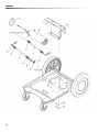
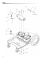
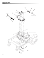
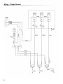
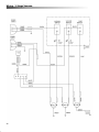
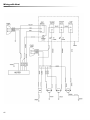
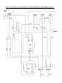
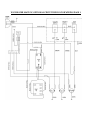
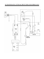
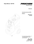
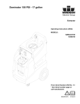
1
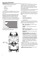
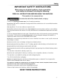
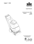
150 PSI
Operating instructions (ENG)
MODELS:
WARRIOR 150
WARRIOR 150-10
WARRIOR 150-05
Read this instructions before using the machine.
760-171
Machine Data Log / Overview
OVERVIEW
The Warrior is an electric powered carpet extractor intended for commercial use. This appliance applies a
cleaning solution to the carpet and then vacuums the soiled water back into the recovery tank.
2
Machine Data Log / Overview. . . . . . . . . . . . . . . . . . 2
Table of Contents . . . . . . . . . . . . . . . . . . . . . . . . . . . 3
How to Use This Manual . . . . . . . . . . . . . . . . . . . . . . 4
Safety
IMPORTANT SAFETY INSTRUCTIONS . . . . . . . . . 5
HAZARD INTENSITY LEVEL . . . . . . . . . . . . . . . . . . 6
Grounding Instructions . . . . . . . . . . . . . . . . . . . . . . .7
Operations
Technical Specifications . . . . . . . . . . . . . . . . . . . . . .8
Controls. . . . . . . . . . . . . . . . . . . . . . . . . . . . . . . . . . .9
Machine Operation . . . . . . . . . . . . . . . . . . . . . . . . .10
Chemicals . . . . . . . . . . . . . . . . . . . . . . . . . . . . . . . . 10
Pre-Run Inspection . . . . . . . . . . . . . . . . . . . . . . . . . 11
Equipment Set-up . . . . . . . . . . . . . . . . . . . . . . . . . . 11
Heater Operation . . . . . . . . . . . . . . . . . . . . . . . . . . 11
Cleaning . . . . . . . . . . . . . . . . . . . . . . . . . . . . . . . . . 12
PARTS
Table of Contents
Control Panel . . . . . . . . . . . . . . . . . . . . . . . . . . . . 19
Control Panel with Heat . . . . . . . . . . . . . . . . . . . . 21
Electrical with 2 Stage Vacuum . . . . . . . . . . . . . . 23
Electrical with Heat . . . . . . . . . . . . . . . . . . . . . . . . 25
Frame . . . . . . . . . . . . . . . . . . . . . . . . . . . . . . . . . . 27
Heater . . . . . . . . . . . . . . . . . . . . . . . . . . . . . . . . . . 29
Labels . . . . . . . . . . . . . . . . . . . . . . . . . . . . . . . . . . 31
Pump. . . . . . . . . . . . . . . . . . . . . . . . . . . . . . . . . . . 33
Pump with Heat. . . . . . . . . . . . . . . . . . . . . . . . . . . 35
Recovery . . . . . . . . . . . . . . . . . . . . . . . . . . . . . . . . 37
Solution . . . . . . . . . . . . . . . . . . . . . . . . . . . . . . . . . 39
Vacuum, 2-Stage/3-Stage . . . . . . . . . . . . . . . . . . . 41
Wiring 2-2 Stage Vacuum . . . . . . . . . . . . . . . . . . 43
Wiring 2-3 Stage Vacuum . . . . . . . . . . . . . . . . . . . 44
Wiring With Heater . . . . . . . . . . . . . . . . . . . . . . . . . 45
Circuit Indicator Option . . . . . . . . .. . . .. . . . . . . . . . 46
Warrior Warranty. . . . . . . . . . . . . . . . . . . . . . . . . . . 52
Maintenance
Periodic Maintenance . . . . . . . . . . . . . . . . . . . . . . . 13
Daily/Regular Maintenance. . . . . . . . . . . . . . . . . . . 13
Vacuum Motor Replacement . . . . . . . . . . . . . . . . . 14
Solution Pump Replacement . . . . . . . . . . . . . . . . . 15
Troubleshooting . . . . . . . . . . . . . . . . . . . . . . . . . . . 16
3
How to Use This Manual
This manual contains the following sections:
•
•
•
•
•
How to Use This Manual
Safety
Operations
Maintenance
Parts List
The HOW TO USE THIS MANUAL section will tell you
how to find important information for ordering correct
repair parts.
Parts may be ordered from authorized dealers. When
placing an order for parts, the machine model and
machine serial number are important. Refer to the
MACHINE DATA box which is filled out during the
installation of your machine. The MACHINE DATA box
is located on the inside of the front cover of this manual.
Model:
Date of Purchase:
Serial Number:
Dealer:
Address:
Phone Number:
Sales Representative:
The model and serial number of your machine is
located approximately where shown.
Serial Number
Tag
The SAFETY section contains important information
regarding hazardous or unsafe practices of the
machine. Levels of hazards are identified that could
result in product damage, personal injury, or severe
injury resulting in death.
The OPERATIONS section is to familiarize the operator
with the operation and function of the machine.
The MAINTENANCE section contains preventive maintenance to keep the machine and its components in
good working condition. They are listed in this general
order:
•
•
•
•
•
Maintenance
Lubrication
Vacuum Motor Replacement
Solution Pump Replacement
Troubleshooting
The PARTS LIST section contains assembled parts
illustrations and corresponding parts list. The parts lists
include a number of columns of information:
•
REF – column refers to the reference number
on the parts illustration.
• PART NO. – column lists the part number for
the part.
• PRV NO. – reference number.
• QTY – column lists the quantity of the part used
in that area of the machine.
• DESCRIPTION – column is a brief description
of the part.
• SERIAL NO. FROM – If this column has an (*)
and a Reference number, see the SERIAL
NUMBERS page in the back of your manual. If
column has two asterisk (**), call manufacturer
for serial number. The serial number indicates
the first machine the part number is applicable
to. The main illustration shows the most current
design of the machine. When a boxed illustration is shown, it displays the older design.
• NOTES – column for information not noted by
the other columns.
NOTE: If a service or option kit is installed on your
machine, be sure to keep the KIT INSTRUCTIONS
which came with the kit. It contains replacement parts
numbers needed for ordering future parts.
NOTE: The manual part number is located on the
lower left corner of the front cover.
4
Safety
IMPORTANT SAFETY INSTRUCTIONS
When using an electrical appliance, basic precaution
must always be followed, including the following:
READ ALL INSTRUCTIONS BEFORE USING THIS MACHINE.
This machine is for commercial use.
To reduce the risk of fire, electric shock, or injury:
Connect to a properly grounded outlet. See Grounding Instructions.
Do not leave the machine unattended. Unplug machine from outlet when not in use and before maintenance or service.
Use only indoors. Do not use outdoors or expose to rain.
Do not allow machine to be used as a toy. Close attention is necessary when used by or near children.
Use only as described in this manual. Use only manufacturer's recommended components and attachments.
Do not use damaged electrical cord or plug. Follow all instructions in this manual concerning grounding
the machine. If the machine is not working properly, has been dropped, damaged, left outdoors, or
dropped into water, return it to an authorized service center.
Do not pull or carry machine by electrical cord, use as a handle, close a door on cord, or pull cord around
sharp edges or corners.
Do not run machine over cord. Keep cord away from heated surfaces.
Do not unplug machine by pulling on cord. To unplug, grasp the electrical plug, not the electrical cord.
Do not handle the electrical plug or machine with wet hands.
Do not operate the machine with any openings blocked. Keep openings free of debris that may reduce
airflow.
This machine is intended for cleaning carpet only.
Do not vacuum anything that is burning or smoking, such as cigarettes, matches, or hot ashes.
This machine is not suitable for picking up health endangering dust.
Turn off all controls before unplugging.
Machine can cause a fire when operating near flammable vapors or materials. Do not operate this
machine near flammable fluids, dust or vapors.
This machine is suitable for commercial use, for example in hotels, schools, hospitals, factories, shops
and offices for more than normal housekeeping purposes.
Maintenance and repairs must be done by qualified personnel.
If foam or liquid comes out of machine, switch off immediately.
SAVE THESE INSTRUCTIONS
5
Safety
The following symbols are used throughout this guide as indicated in their descriptions:
HAZARD INTENSITY LEVEL
There are three levels of hazard intensity identified by signal words -WARNING and CAUTION and FOR SAFETY.
The level of hazard intensity is determined by the following definitions:
WARNING - Hazards or unsafe practices which COULD result in severe personal injury or death.
CAUTION - Hazards or unsafe practices which could result in minor personal injury or product or property damage.
FOR SAFETY: To Identify actions which must be followed for safe operation of equipment.
Report machine damage or faulty operation immediately. Do not use the machine if it is not in proper operating
condition. Following is information that signals some potentially dangerous conditions to the operator or the equipment. Read this information carefully. Know when these conditions can exist. Locate all safety devices on the
machine. Please take the necessary steps to train the machine operating personnel.
FOR SAFETY:
DO NOT OPERATE MACHINE:
Unless Trained and Authorized.
Unless Operation Guide is Read and understood.
In Flammable or Explosive areas.
In areas with possible falling objects.
WHEN SERVICING MACHINE:
Avoid moving parts. Do not wear loose clothing; jackets, shirts, or sleeves when working on the machine.
Use only manufacturer approved replacement parts.
6
Safety
Grounding Instructions
THIS PRODUCT IS FOR COMMERCIAL
USE ONLY.
ELECTRICAL:
In the USA this machine operates on a standard 15
amp 115V, 60 hz, A.C. power circuit. The amp, hertz,
and voltage are listed on the data label found on each
machine. Using voltages above or below those
indicated on the data label will cause serious damage
to the motors.
EXTENSION CORDS:
If an extension cord is used, the wire size must be at
least one size larger than the power cord on the
machine, and must be limited to 50 feet (15.5m) in
length.
GROUNDING INSTRUCTIONS:
This appliance must be grounded. If it should malfunction or break down, grounding provides a path of least
resistance for electric current to reduce the risk of
electric shock. This appliance is equipped with a cord
having an equipment-grounding conductor and
grounding plug. The plug must be inserted into an
appropriate outlet that is properly installed and
grounded in accordance with all local codes and ordinances.
Improper connection of the equipment-grounding
conductor can result in a risk of electric shock.
Check with a qualified electrician or service person
if you are in doubt as to whether the outlet is
properly grounded. Do not modify the plug
provided with the appliance - if it will not fit the
outlet, have a proper outlet installed by a qualified
electrician.
7
Operations
ITEM
MODEL
ALL
WARRIOR
150 &150-05
WARRIROR
150-10
MEASURE
115 Volt, 60 hz, 15A
150 psi
13 Gal
11Gal
43 inches
30 inches
22 inches
Dual 2 Stage
113 lbs
208 lbs
1 X 25 feet
Dual 2 Stage
120 lbs
215 lbs
2 X 25 feet
1850 watts
Electrical
Solution Pump
Solution Capacity
Recovery Capacity
Height
Length
Width
Vaccum Motor
Weight- Empty
Weight-Full Solution
Power cord
Vaccum Motor
Weight- Empty
Weight-Full Solution
Power cord
Heater
Length
Width
Height
8
Operations
Controls
2
1
3
5
4
CIRCUIT
INDICATOR
9
10
7
8
6
1. Vacuum Accessory Tool Hook-up
6. Heater Temperature Light (Units with Heat Only)
2. Solution Pump Switch
7. Breaker for Vacuum 2
3. Vacuum 1 Switch
8. Breaker for Vacuum 1
4. Vacuum 2 Switch
9. Solution Accessory Tool Hook-up
5. Heater Switch with On Light (Units with Heat Only)
9
10.
Circuit Indicator
Operations
Machine Operation
Care must be exercised in the use of all chemicals.
Chemicals are poisonous and can pose a health risk.
Read and follow manfacturers instructions regarding
dangers and correct usages.
Only use chemicals approved for use with this
machine. Use of non-compatible chemicals may cause
machine damage and will not be covered under the
warranty. Carefully read ingredients on manfacturer's
label before using any product in this machine.
Do not let pump run dry.
The internal parts of the pump used in the machine are
suitable for use with most carpet cleaning chemicals.
But they are susceptible to chemical attack from some
cleaning substances, such as hydrocarbon solvents
and chlorinated bleaches. These non-compatible
materials are not of the type used for carpet cleaning.
Do not let pump run unattended.
Chemicals
Suitable Chemicals
•
•
•
•
•
Alkalis
Detergents
Hydroxides
Soaps
Vinegar
Non-Compatible
•
•
•
•
•
•
•
•
•
•
•
•
•
Aldehydes
Aromatics Hydrocarbons
SP Butyls
Carbon Tetrachloride
Clorox*
Chlorinated Bleaches
Chlorinated Hydrocarbons
Lysol*
Methyl Ethel Ketone (MEK)
Perchorethylene (perc)
Phenolics
Trichlorethylene
D-Limonene
*Registered Trademark
10
Operations
Pre-Run Inspection
1. Check all ttings and connectors for proper
assembly.
2. Check all hoses for leaks. Repa ir or replace any
dama ged hos es.
3. Check power cord(s) for any damage. If damaged,
replace.
Equipment Set-up
1. Plug power cord from machine into properly
grounded wall outlet.
2. Turn vacuum motor swith on and off to make sure
there is electrical power at machine.
3.
150 PSI pump priming instructions:
- Fill fresh water tank with hot water and cleaning detergent
- Attach prime hose to quick connect on mac hine
- Place the other end of prime hose into va cuum
port and hold
- turn vacuum and pump switches o n
th rough the prime hose, this indicates pump is pr imed
prime hose
4. Connect vac hose to ma chine. Slide the swivel
tlet on the tank.
5. Connect the hose to your ma chine and wand . Pull
back the knurled collar on the quick disconnect
coupler and push onto the connection on the
chassis. To avoid leaks , check that a posit ive
connection was ma de.
NOTE: Wand orifice must be equivalent or larger
than an 03 nozzle.
11
Heater Operation
NOTE:
Units with Heat Only.
The solu
gs on the machine will become
nt
extremely hot during operation. Allow
time to cool, or run solution through the machine
disconnecting or
with the heater
performing any maintenance on the heater.
Plug the two power cords into separate grounded
circuits. The heater draws 15 amps of current.
Turn the solution pump ON. Fully prime the solution
system before turning heater on.
Turn the hea ter switch on. The red light on the heater
switch will be on when the heater switch is on. The red
heater temperature light will be on when the hea ter is
en the heater reaches
active and will turn
maximum temperature.
On initial start-up the heater will ta ke a few minutes to
reach operating temperature.
When turning the pump and Heater OFF, make certain that you
turn the heater OFF first.
Operations
Cleaning
Always use defoamer if foaming occurs. Foam will
suspend large particles that may damage
vacuum(s) as well as allow liquid into the vacuum
motor(s) without activating the float shutoff.
1. Prior to cleaning, make certain that the nozzle is
functioning properly.
a. To check, hold the wand about one foot above
the surface to be cleaned and open the wand
valve. A full spray should be observed from the
nozzle.
b. If the nozzle is not showing a full spray pattern,
adjust nozzle for proper pattern, clean, or replace
nozzle.
2. Normally, chemical is applied on the push stroke of
the wand when cleaning. Vacuuming is done on
the pull stroke. For heavily soiled carpets the wand
may be used in a scrubbing manner, applying
chemical in both the push and pull stroke.
3. When cleaning, keep the working opening (wand
mouth) flat on the surface being cleaned. Keep the
wand moving when the valve is open.
4. The shutoff float inside the vacuum tank will
impede the vacuum flow when the vacuum tank is
full. When this occurs, empty the vacuum tank by
opening the dump valve and dispose of the waste
in a proper manner.
Once the vacuum tank has been emptied, you may
once again proceed with cleaning.
12
Maintenance
Periodic Maintenance
Twice a month, flush a white vinegar solution (one
quart vinegar to two gallons of water) or anti-browning
solution (mixed as directed) through the machine. This
will prevent build-up of alkaline residue in the system.
If spray jets become clogged, remove the spray tips,
wash them thoroughly, and blow dry.
NOTE: Do not use pins, wires, etc. to clean nozzles
as this could destroy the spray pattern.
Periodically inspect all hoses, electrical cables and
connections on your machine. Frayed or cracked
hoses should be repaired or replaced to eliminate
vacuum or solution pressure loss. The electrical cable
must be well insulated and cable connector screw kept
tight. If the cable insulation is broken or frayed, repair
or replace immediately. Don't take chances with
elctrical fire or shock.
Daily/Regular Maintenance
Before making any repairs or adjustments to the
machine, disconnect the power cords from the
electrical source.
1. Empty unused cleaning solution from the solution
tank.
2. Inspect and clean filter screen in solution tank.
3. Flush pumping system with 1 to 2 gallons of clean
water.
4. After each use, rinse tank with fresh water. Periodically inspect the recovery tank and decontaminate
if necessary, using a Hospital Grade Virucide or a
10-1 bleach to water solution. Waste water should
be disposed of properly.
Do not allow machine to freeze.
SERVICE SCHEDULE
Check machine for cord damage
Check recovery dome and gasket for damage and cleanliness
Check hoses for wear, blockages, or damage
Check handles, switches, and knobs for damage
Run one gallon of water through system
Clean out recovery tank and check float valve to make sure it moves freely
Clean out solution tank and remove and clean vacuum intake screen
Clean outside of all tanks and check for damage
Run vac motor for at least one minute to allow motor to dry
Store with dome off tank to allow the tank to dry
Check all gaskets for wear and leakage
Check pump pressure; observe spray pattern and check with gauge if
necessary
Check and clean solution screen
Check cables for fraying
Check overall performance of machine
Check vac motor carbon brushes
13
DAILY WEEKLY QUARTERLY
*
*
*
*
*
*
*
*
*
*
*
*
*
*
*
*
Maintenance
Vacuum Motor Carbon Brushes Replacement
Only qualified maintenance personnel are to
perform the following repairs.
Vacuum Motor Replacement
1. Turn off all switches and unplug machine.
End Cap
Carbon
Brushes
2. Remove hardware under front of machine to
access component compartment.
WARNING: The
green ground wire
must be attached for
safe operation. See
wiring diagram.
3. Remove vacuum motor cover and disconnect
motor wires.
4. Remove the vacuum motor.
5. Reverse process to install vacuum motor.
If armature commutator is grooved, extremely pitted
or not concentric, the motor will need to be replaced
or sent to a qualified service center.
Important:
These brushes wear quicker as the length shortens
due to increased heat. Spring inside brush housing
will damage motor if brushes are allowed to wear
away completely.
3 [9.5mm]
8
Periodically check the length of the carbon brushes.
Replace both carbon brushes when either is less than
3/8" (9.5mm) long.
14
Maintenance
Solution Pump Replacement
Only qualified maintenance personnel are to perform the following repairs.
15
Maintenance
Troubleshooting
PROBLEM
Loss of Power
Electrical shock
Vac motor speed
varies or doesn't run
CAUSE
Unit not plugged in
Dead electrical circuit
Faulty power cord
Receptacle not grounded
Internal wiring problem
Vacuum circuit breaker tripped
Faulty vacuum motor
Faulty switch
Loose vacuum dome
Crack in dome or poor joint
Loss of vacuum
Pump runs no solution
Lint or dirt clogging vacuum screen
Loose cuffs on vacuum hose
Vac motor seals leaking
Floor tool vac chamber clogged
Vacuum hose damaged
Recovery tank full / Float ball stuck in
the up position
Pump inlet screen plugged
Pump not primed
Internal or external solution line
damaged and leaking
SOLUTION
Connect unit to 3 prong grounded outlet.
Check building circuit breaker or fuse box.
Replace
Contact an electrician to check building's wiring
Have a trained service technician check
machine's wiring
Reset Breaker
Replace
Replace
Center and seal dome over tank
Replace or repair using acrylic plastic cement
only
With power off clean screen
Tighten cuffs turning counterclockwise
Replace
Wash out with hose. Pick lint out with a wire
Replace
Turn off power, drain recovery tank.
Clean inlet screen
Press trigger to open valve on cleaning wand to
relieve air lock.
Replace
Pump runs, loss of
pressure
Internal pump components wearing out Replace, see pump kit components
Pump will not run
Faulty switch
Loose wiring
Solution hose fitting
hard to connect
Corrosion on fittings.
Carpet not getting
clean
Carpet too wet
Carpet browning
Solution not flowing
properly
Severe soil conditions
Over saturation
Leaving carpet too wet
Too much chemical
Solution hose connection
Faulty pump
Faulty floor tool valve / Nozzle
Faulty pump switch
Replace
Repair or replace
Clean with steel wool. Soak in acetic acid (white
vinegar). Lubricate lightly with silicone base
lubricant.
Make several passes at right angles to each
other. Use a pre-spray.
Make several passes without spray
Check for loss of vac pressure
Check label for correct solution concentration
Check for positive connection
Repair or replace
Repair or replace
Repair
16
Notes:
17
PARTS
Control Panel
4
1
2
5
12
10
3
11
7
6
19
8
9
Control Panel
REF
1
2
3
4
5
6
7
8
9
10
11
12
PART NO
415-155
415-156
580-010
555-184
410-205
305-075
340-180
845-081
475-040
400-150
703-008
340-162
DESCRIPTION
NOTE
FW, 1/2 SS
FW, 1/2 SS (Stand/Max OD)
Q.C. 1/4 FEM (Close)
Elbow 45,Street 1/4
MS, 10-32 x 1/2 Panphil SS
Switch, SPST 2-Posi on Rocker
Boot, Seal Breaker
Control Panel
Gasket 1/8 x 1
Locknut 10 x 32 Nylon SS
Decal Warrior Panel
Breaker 15A
20
Control Panel with Heat
5
21
Control Panel with Heat
REF
1
2
3
4
5
6
7
8
9
10
11
12
13
14
PART NO
415-155
415-156
580-010
555-184
410-205
305-075
340-180
845-081
475-040
400-150
703-008
340-162
320-110
305-076
DESCRIPTION
NOTE
FW, 1/2 SS
FW, 1/2 SS (Stand/Max OD)
Q.C. 1/4 FEM (Close)
Elbow 45,Street 1/4
MS, 10-32 x 1/2 Panphil SS
Switch, SPST 2-Posi on Rocker
Boot, Seal Breaker
Control Panel
Gasket 1/8 x 1
Locknut 10 x 32 Nylon SS
Decal Warrior Panel
Breaker 15A
Lamp, Panel 110V
Switch, Lighted 2-Posi on Rocker
22
Electrical with 2 Stage Vacuum
23
Electrical with 2 Stage Vacuum
REF
1
2
3
4
5
6
7
PART NO
400-165
405-615
335-015
325-015
415-125
465-084
315-015
DESCRIPTION
Locknut, 1/2 Steel/Strain Relief
Bolt, 1/4 x 1/2
Strain Relief, 14 Gauge
Connector, 5 Posi on, Push Wire
FW, 1/4 SS
BRKT, Cord Strain Relief
Cord, 25’ Black 14/3 SJTW-A
NOTE
24
Electrical with Heat
25
Electrical with Heat
REF
1
2
3
4
5
6
7
PART NO
400-165
410-205
335-015
325-015
415-125
465-084
315-015
DESCRIPTION
Locknut, 1/2 Steel/Strain Relief
MS, 10-32 x 1/2 Panphil SS
Strain Relief, 14 Gauge
Connector, 5 Posi on, Push Wire
FW, 1/4 SS
BRKT, Cord Strain Relief
Cord, 25’ Black 14/3 SJTW-A
NOTE
26
Frame
7
8
27
Frame
REF
1
2
3
4
5
6
7
8
PART NO
455-075
455-090
400-010
415-120
415-165
455-085
455-080
845-090
DESCRIPTION
Caster, Swivel 4”
Hubcap, 5/8 Shaft
Hex Nut, 1/4 x 20 Zinc
FW, 1/4 zinc
FW, 5/8 SS
Hubcap, 9.5 Wheel
Wheel, 12 x 2.25
Frame, Base, Warrior
NOTE
28
Heater
29
Heater
REF
1
2
3
4
5
6
7
8
9
10
11
12
PART NO
572-042
572-125
581-015
581-065
550-035
490-005
425-040
555-210
555-208
415-125
405-615
465-086
DESCRIPTION
Blue Neptune 1/4
Pulse Hose 3/8
Crimp FTNG, 1/4 HP Hose - 1/4 MPT SVL
Crimp FTNG, 3/8 Pulse Hose – 1/4 MPT SVL
Check valve, 1/4 FM x FM
Foamed Casing, Round 1850W
Clamp #60
Elbow 90, 3/8 MPT x 1/4 MPT
Elbow 90, 1/4 Street Extruded
FW, 1/4 SS
Bolt, 1/4 x 1/2 SS
Bracket, Heater Mount
NOTE
30
Labels
2
3
1
31
Labels
REF
1
2
3
PART NO
703-006
703-007
703-008
DESCRIPTION
Decal Warrior LH
Decal Warrior RH
Decal Warrior Panel
NOTE
32
Pump
33
Pump
REF
1
2
3
4
5
6
7
8
9
10
11
12
13
14
15
16
PART NO
511-105
585-110
510-090
425-005
555-182
572-155
572-041
400-135
415-125
405-020
582-080
555--364
555-254
410-225
560-325
333-005
DESCRIPTION
Pump, 150 PSI 115V
Nylon, 90 Barb 1/2 x 3/8 NPT
Nylon, 90 Barb 3/8 x 3/8 NPT
Clamp #6
Elbow 45, 1/4 FEM. Extruded
Poly Spring hose, 1/2
L.P. Hose 3/8
Locknut, ¼ x 20 Nylon Zinc
FW, 1/4 SS
Bolt, 1/4 x 1-1/4 SS
swivel, 1/4 M x 1/4 F
Hose Barb, 3/8 Barb x 1/4 MPT
Ferrule, 3/8 Hose
SMS, 10 x 1/2 Pan RB Zinc
Guard, Finger 4” Muffin Fan
Fan Muffin 4” 115V
NOTE
34
Pump with Heat
2
4
8
6
9
1
TOHEATER
FROM SOLUTION TANK
11
7
11
5
3
9
10
35
Pump with Heat
REF
1
2
3
4
5
6
7
8
9
10
11
PART NO
511-105
585-110
555-210
425-005
550-035
572-155
572-125
400-135
415-125
405-615
581-065
DESCRIPTION
Pump, 150 PSI 115V
Nylon, 90 Barb 1/2 x 3/8 NPT
Elbow 90, 3/8 MPT x 1/4 MPT
Clamp #6
Check valve, 1/4 FM x FM
Poly Spring hose, 1/2
Pulse Hose 3/8
Locknut, ¼ x 20 Nylon Zinc
FW, 1/4 SS
Bolt, 1/4 x 1/2 SS
Crimp FTNG, 3/8 Pulse Hose – 1/4 MPT SVL
NOTE
36
Recovery
10
22
21
37
Recovery
REF
1
2
3
4
5
6
7
8
9
10
11
12
13
14
15
16
17
18
19
20
21
22
PART NO.
545-100
585-210
590-020
475-125
400-116
405-026
405-615
410-125
415-125
415-128
415-305
455-070
355-230
597-015
495-320
597-062
465-082
590-419
410-265
595-010
415-420
465-066
DESCRIPTION
Dump Valve, 1 1/2”
Clear Cover, 6” C/W Ring
PVC ELB 1 1/2” 90, S x FIPT
Gasket 6” Access Cover Clear
Locknut, 5/16 x18 Nylon SS
Bolt, 1/4 x 1-1/2 Zinc
CS, 1/4 x 1/2 SS (Hex HD)
SMS, 8 x 5/8 Pan Rob SS
FW, 1/4 SS
FW, 5/16 SS
FNDW, 1/4 SS
Wheel, 3”
Vac Bolt Spacer 3/8 x 1-1/8
Adpt (RM) 30 Degree, Float 2”
Rec tank, Warrior Blue
Float Screen Cage 2”
BRKT, Cord Mount
PVC Hose Barb, 2” HB x 1 1/2” MPT
MS, 5/16 x 2-1/2 Pan Phil SS
ABS Pipe, 2”
Machined Washer 1 7/8
Brace, Warrior Tank (W/O Heat Model)
NOTES:
38
Solution
39
Solution
40
Vacuum, 2-Stage, 3-Stage
1
4
12A
12B
9
5
12A
12B
10
11A
11B
3
2
6
7
4
8
41
Vacuum, 2-Stage, 3-Stage
REF
1
2
3
4
5
6
7
8
9
10
11A
11B
12A
12B
PART NO.
400-135
410-221
425-015
415-120
415-115
355-220
475-072
405-065
410-136
570-020
355-300
355-305
355-310
355-315
DESCRIPTION
Locknut, 1/4 x 20 Nylon Zinc
MS, 10-32 1-1/2 RH Soc
Clamp, #28
FW, 1/4 Zinc
FW, #10 SS
Manifold, Dual Vacuum
Gasket, Vacuum Manifold
6” Bolt
SMS, 8 x 3/4
Vac Hose 2”
Vac , 2-Stage
Vac , 3-Stage
Housing, Vac Motor, 2-Stage
Housing, Vac Motor, 3-Stage
NOTES:
42
43
Wiring - 3 Stage Vacuum
44
Wiring with Heat
45
WARRIOR 150 MODEL W/ OPTIONAL
CIRCUIT INDICATOR
CIRCUIT
INDICATOR
RELAY 120V
SOCKET
RELAY 240V
CIRCUIT INDICATOR PARTS LIST
REF
1
2
3
4
5
6
7
PART NO.
845-036
320-111
305-057
305-058
305-059
703-108
465-045
DESCRIPTION
Plate
Lamp
Relay 120V
Socket
Relay 240V
Decal
Relay Bracket
NOTES:
W15 2-3 STAGE VAC W/ OPTIONAL CIRCUIT INDICATOR WIRING PAGE 1
W15 2-3 STAGE VAC W/ OPTIONAL CIRCUIT INDICATOR WIRING PAGE 2
W15 HEATER MATE W/ OPTIONAL CIRCUIT INDICATOR WIRING PAGE 1
W15 HEATER MATE W/ OPTIONAL CIRCUIT INDICATOR WIRING PAGE 2