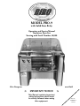
1
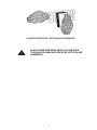
SIR STEAK
MODEL
MODEL PRO-9
PRO-9
with
Relay
withSolid
Solid State
State Relay
Operation
Manual
Operationand
and Service
Service Manual
StartingTenderizer
with SerialParts
Number
List30,000
Starting with Serial Number 30,000
Biro Designed
Biro Built
+
IMPORTANT NOTICE
This Manual contains important
safety instructions which must
be strictly followed when using
this equipment.
+
Part No.
T3400-091
1-10-38
Part No.
T3400-091
TABLE OF CONTENTS
Page
NOTICE
TOOWNERS
OWNERS
AND
OPERATORS
NOTICE TO
AND
OPERATORS
. . . .... .. .. .. .. .. .. .. .. ..... .. .. .. .. .. .. .. ..... .. .. .. .. .. .. .. ....... .. .. .. .. .. .. .. . 11
SAFETY
TIPS.. .. .. .. ..... .. .. .. .. .. .. ..... .. .. .. .. .. .. ..... .. .. .. .. .. .. ..... .. .. .. .. .. ..... .. .. .. .. .. .. ..... .. .. .. .. .. .. ..... .. .. .. .. .. .. ..... .. .. 22
SAFETY TIPS
INSTALLATION . .. . . . . .. ..... .. . . . . .. ..... .. . . . .. .. ... .. .. . . . .. ..... .. .. . . . .. ..... .. . . . . .. ..... .. . . . . .. ..... .. . . . .. .33
INSTALLATION.
OPERATION . . ... .. .. .. .. .. .. ..... .. .. .. .. .. .. ..... .. .. .. .. .. .. ..... .. .. .. .. .. .. ..... .. .. .. .. .. .. ... .. .. .. .. .. .. ..... .. .. .. .. .. .. ..... .. .. .. .. .. .. .44
OPERATION.
TO PROCESS PRODUCT . . . . . . . . . . . . . . . . . . . . . . . . . . . . . . . . . . . . . . . . . . . . . . . . 4
TO PROCESS PRODUCT. . . . . . . . . . . . . . . . . . . . . . . . . . . . . . . . . . . . . . . . . . . . . . . . . . . . . .4
TO UNJAM OR UNCLOG. . . . . . . . . . . . . . . . . . . . . . . . . . . . . . . . . . . . . . . . . . . . . . . . . 5
TO UNJAM OR UNCLOG. . . . . . . . . . . . . . . . . . . . . . . . . . . . . . . . . . . . . . . . . . . . . . . . . . . . . 5
CLEANING . . . . . . . . . . . . . . . . . . . . . . . . . . . . . . . . . . . . . . . . . . . . . . . . . . . . . . . . . . . . . . . . . 6
CLEANING. . . . . . . . . . . . . . . . . . . . . . . . . . . . . . . . . . . . . . . . . . . . . . . . . . . . . . . . . . . . . . . . . . . . . . . . . 6
CLEANING THE SAFETY COVER AND CASE . . . . . . . . . . . . . . . . . . . . . . . . . . . . . . . . . 6
CLEANING THE SAFETY COVER AND CASE. . . . . . . . . . . . . . . . . . . . . . . . . . . . . . . . . .6
CLEANING THE CRADLE AND BLADE ASSEMBLIES . . . . . . . . . . . . . . . . . . . . . . . . . . . 6
6
CLEANING
MAINTENANCE
. . .THE
. . . . .CRADLE
. . . . . . . .AND
. . . . .BLADE
. . . . . . .ASSEMBLIES.
. . . . . . . . . . . .. .. .. .. .. .. ..... .. .. .. .. .. .. ..... .. .. .. .. .. .. .13
. . .9
ASSEMBLY
OF
WIRING
DIAGRAMS.
. . PRO-9
. . . . . . CRADLES.
. . . . . . . . . .. .. .. .. .. .. ..... .. .. .. .. .. .. ..... .. .. .. .. .. .. ..... .. .. .. .. .. .. ..... .. .. .. .. .. .. .15-16
PARTS DIAGRAMS .. .. ..... .. . . . .. ..... .. .. . . . .. ..... .. .. . . . .. ..... .. . . . . .. ..... .. . . . .. .. ..... .. . . . .. ..... .. .. . . . .. ..... .. 17
MAINTENANCE.
14
PARTS LIST/ORDERING.
. . .&. 27
WIRING
DIAGRAMS. . ... .. .. .. .. .. .. ..... .. .. .. .. .. ..... .. .. .. .. .. .. ..... .. .. .. .. .. .. ..... .. .. .. .. .. .. ..... .. .. .. .. .. .. ..... .. .16
17
OPERATOR’S SIGNATURE PAGE. . . . . . . . . . . . . . . . . . . . . . . . . . . . . . . . . . . . . . . . . . . . . . . . 30
PARTS DIAGRAMS. . . . . . . . . . . . . . . . . . . . . . . . . . . . . . . . . . . . . . . . . . . . . . . . . . . . . . . . . . . . . . . . . . 18
LIMITED WARRANTY . . . . . . . . . . . . . . . . . . . . . . . . . . . . . . . . . . . . . . . . . . . . . . . . . . . . . . . . . 31
PARTS LIST/ORDERING. . . . . . . . . . . . . . . . . . . . . . . . . . . . . . . . . . . . . . . . . . . . . . . . . . . . . . . . . . . . 28
OPERATOR’S SIGNATURE PAGE. . . . . . . . . . . . . . . . . . . . . . . . . . . . . . . . . . . . . . . . . . . . . . . . . . . . 31
LIMITED WARRANTY. . . . . . . . . . . . . . . . . . . . . . . . . . . . . . . . . . . . . . . . . . . . . . . . . . . . . . . . . . . . . . 32
— NOTES —
NOTICE TO OWNERS AND OPERATORS
BIRO’s products are designed to process food products safely and efficiently. Unless the operator is properly trained and supervised, however, there is the possibility of a serious injury. It is the
responsibility of the owner to assure that this machine is used properly and safely, strictly following
the instructions contained in this Manual and any requirements of local law.
No one should use or service this machine without proper training and supervision. All operators should read and be thoroughly familiar with the procedures contained in this Manual. Even so,
BIRO cannot anticipate every circumstance or environment in which its products will be used.
You, the owner and operator, must remain alert to the hazards posed by the function of this equipment — particularly the SHARP ROTATING BLADES. No one under eighteen (18) years of age
should operate this equipment. If you are uncertain about a particular task, ask your supervisor.
This Manual contains a number of safe practices in the SAFETY TIPS section. Additional warnings are placed throughout the Manual. Warnings related to your personal safety are indicated by:
OR
Warnings related to possible damage to the equipment are indicated by:
If any warning label, or Manual becomes misplaced, damaged, or illegible, please contact your
nearest Distributor or BIRO directly for a replacement.
Remember, however, this Manual or the warning labels do not replace the need to be alert and
to use your common sense when using this equipment.
This Manual applies to machines with serial number 30,000 and higher; to machines with redesigned SD gear box, serial number 52,902 and higher; and machines with redesigned heavy duty
gear box, serial number 52,884 and higher.
- NOTE A copy of this manual is included with each PRO-9 TENDERIZER
The descriptions and illustrations contained in this manual are not binding.
The manufacturer reserves the right to introduce any modification without
updating the manual.
1
SAFETY TIPS
SHARP ROTATING BLADES
TO AVOID SERIOUS PERSONAL INJURY
· NEVER Touch This Machine without Training and Authorization by Your Supervisor.
· ALWAYS Read Operation and Service Manual BEFORE Operating, Cleaning, or Servicing.
· ALWAYS Keep Hands Clear of Blades and Moving Parts.
· ONLY Use a Qualified Electrician to Install According to Local Building Codes: Machine MUST
Be Properly Grounded.
· ONLY Install on Level, Non-Skid Surface in Clean, Well-Lighted Work Area Away from Children
and Visitors.
· DO NOT Tamper With, Bypass or Remove the Safety Cover, Interlock Switch, or Toggle
Switch.
· DO NOT Operate With the Safety Cover in Raised Position or Removed. Safety Cover MUST
Be Down During Operation.
· ONLY Operate Machine by Using the Machine’s ON/OFF Toggle Switch. ALWAYS Turn Off
Toggle Switch When Not in Use.
· DO NOT Wear Gloves While Operating.
· ALWAYS Turn Off and Unplug Machine From Power Source and Perform Lockout/Tagout
Procedures BEFORE Cleaning, Servicing, or Attempting to Unjam or Unclog.
· ALWAYS Wear Wire Mesh Safety Gloves When Touching or Handling Stew Cutter Attachments.
· NEVER Leave Machine Unattended While Running.
· PROMPTLY REPLACE Any Worn or Illegible Warning Labels.
· USE ONLY BIRO Parts and Accessories Properly Installed.
2
I. INSTALLATION
TO AVOID SERIOUS PERSONAL INJURY, PROPERLY INSTALL
EQUIPMENT IN ADEQUATE WORK AREA
· ALWAYS Use Qualified Technician and Electrician for Installation.
· ALWAYS Install Equipment in Work Area with Adequate Light and Space.
· ONLY Operate on a Solid, Level, Non-Skid Surface.
· NEVER Bypass, Alter, or Modify This Equipment in Any Way From Its Original Condition.
· NEVER Operate With Safety Cover in raised Position or Removed.
· NEVER Operate Without all Warnings Attached.
1. Read this Manual thoroughly before installation and operation. Do not proceed with installation and operation if
you have any questions or do not understand anything in this Manual. Contact your local Distributor, or BIRO
first.
2. Install machine on a level, solid, non-skid surface in a well-lighted work area away from children and visitors.
3. Machine must be properly grounded. Use a qualified electrician to install according to local building codes.
4. Make sure ON/OFF toggle switch is in “OFF” position.
5. Lower Safety Cover into operating position as shown in the picture on the front of this Manual.
6. Uncoil electrical cord and plug into specified, grounded outlet. (Specifications for this machine are found on the
plate located on the back of the case.)
7. With Safety Cover lowered into operating position, turn ON/OFF toggle switch to “ON” position. The blades will
begin to rotate. Make sure machine operates properly and is stable and secure on operating surface.
KEEP HANDS CLEAR OF SHARP ROTATING BLADES.
8.
to to
check
safety
interlock
switch
— machine
should
turn off.
8. Raise
RaiseSafety
SafetyCover
Cover
check
safety
interlock
switch
– machine
should
turn
off.
9.
Safety Cover
resume operating.
9. Lower
Turn toggle
switch—tomachine
“OFF”should
position.
Machine is ready for trained operators to process product.
11. Check
Contact
your local
distributor
or BIRO
directly
if you
have any
questions
or problems
with the installation
11.
placement
of all
warning labels.
Machine
is ready
for trained
operators
to process
product.
or
operation
of
the
machine.
12. Contact your local distributor or BIRO directly if you have any questions or problems with the installation or
10. Turn
Check
placement
all warning
labels.
10.
toggle
switch toof“OFF”
position.
operation of the machine.
3
II. OPERATION
SHARP ROTATING BLADES
TO AVOID SERIOUS PERSONAL INJURY
· ONLY Properly Trained Pesonnel Should Use This Equipment.
· ALWAYS Keep Hands Clear of Blades and Other Moving Parts.
· NEVER Operate With Safety Cover in Raised Position or Removed. Safety Cover MUST Be
Down During Operation.
· DO NOT Tamper With, Bypass, or Remove Safety Cover, Interlock Switch, or Toggle Switch.
· ALWAYS Turn Off and Unplug Machine from Power Source and Perform Lockout/Tagout
Procedures Before Cleaning, Servicing, or Attempting to Unjam or Unclog.
· NEVER Leave Unattended While Running.
· ALWAYS Turn Off Toggle Switch When Not in Use.
· ONLY Operate Machine By Using ON/OFF Toggle Switch.
· DO NOT Wear Gloves While Running.
· ALWAYS Wear Wire Mesh Safety Gloves When Touching or Handling Stew Cutter Attachments
for Removal and Cleaning Purposes Only.
A. TO PROCESS PRODUCT
1.
Have product prepared prior to using this machine by slicing to appropriate size.
1. Have product prepared prior to using this machine by slicing to appropriate size.
NOTE:
feed
slotslot
in the
CoverCover
are the
size of product
which can be
NOTE
A. The
Thedimensions
dimensionsofofthethe
feed
in Safety
the Safety
aremaximum
the maximum
size of product
processed.
which can be processed.
2. Make sure Safety Cover is in the down position.
NOTE B. Position Rear Comb T3117 into one of the rear slots which is your processing requirement - tenderizing or knitting. See illustration below.
DO NOT WEAR GLOVES WHILE OPERATING.
3. Turn ON/OFF toggle switch to “ON” position.
COMB POSITIONS
4. Insert the product through
the feed slot FOR
in Safety Cover. Observe the processing through the Safety Cover.
TENDERIZING & KNITTING
5. Product will exit at machine output under Blade Assemblies.
NEVER REACH OR GRAB FOR PRODUCT AT MACHINE
OUTPUT – ALLOW PRODUCT TO DROP AND FULLY CLEAR
ROTATING BLADES BEFORE REMOVING PRODUCT.
2. Make sure Safety Cover is in the down position.
DO NOT WEAR GLOVES WHILE OPERATING.
4
DO NOT WEAR GLOVES WHILE OPERATING.
3. Turn ON/OFF toggle switch to “ON” position.
4. Insert the product through the feed slot in Safety Cover. Observe the processing through the Safety Cover.
5. Product will exit at machine output under Blade Assemblies.
NEVER
REACH
OR GRAB
6. Repeat
procedure
as necessary.
FOR PRODUCT AT MACHINE OUTPUT - ALLOW
PRODUCT TO DROP AND FULLY CLEAR ROTATING BLADES BEFORE
7. TURN
MACHINE “OFF”
BY MOVING TOGGLE SWITCH TO “OFF” POSITION WHEN FINISHED.
REMOVING
PRODUCT.
6. Repeat procedure as necessary.
B. TO UNJAM OR UNCLOG
7. TURN MACHINE “OFF” BY MOVING TOGGLE SWITCH TO “OFF” POSITION WHEN FINISHED.
B. TO UNJAM OR UNCLOG
SHARP ROTATING BLADES
TO AVOID SERIOUS PERSONAL INJURY
SHARP ROTATING BLADES
·
SHARP
ROTATING
AVOID
SERIOUS
PERSONAL
INJURY
ALWAYS Keep HandsTO
Clear
of Blades
and Moving
Parts.BLADES
TO AVOID SERIOUS PERSONAL INJURY
•· ALWAYS
Hands
Clear“OFF”
of Blades
Moving
Parts.
ALWAYSKeep
Turn
Machine
andand
Unplug
From
Power Supply and Perform Lockout/Tagout
Procedures
BEFORE
Attempting
to
Unjam
or
Unclog.
· ALWAYS Keep Hands Clear of Blades and Moving Parts.
• ALWAYS Turn Machine “OFF” and Unplug From Power Supply and Perform Lockout/Tagout Procedures
Attempting
to Unjam
or
Unclog.
· BEFORE
NEVER
Operate
With
Safety
Cover
RaisedFrom
Position
or Removed.
Cover
Must Be Down
ALWAYS
Turn Machine
“OFF”
andinUnplug
Power
Supply andSafety
Perform
Lockout/Tagout
During
Operation.
Procedures
BEFORE
Attempting
UnjamPosition
or Unclog.
• NEVER
Operate
With Safety
Cover intoRaised
or Removed. Safety Cover Must Be Down During
Operation.
· ALWAYS
Wear Wire
Safety
Gloves
When
Touching
or Handling
StewCover
CutterMust
Attachments
NEVER Operate
WithMesh
Safety
Cover
in Raised
Position
or Removed.
Safety
Be Down
for
Removal
and
Cleaning
Purposes
Only.
During Operation.
• ALWAYS
Wear Wire Mesh Safety Gloves When Touching or Handling Stew Cutter Attachments for
Removal
and
Cleaning
Purposes
Only.
1. If machine
becomes
jammed
or clogged,turn
ON/OFF
toggle switch
to “OFF” Stew
position
and UNPLUG
· ALWAYS
Wear
Wire Mesh
Safety
Gloves When
Touching
or Handling
Cutter
Attachments
machine from power source and perform lockout/tagout procedures.
for Removal
and
Cleaning
Purposes
Only.
1. If machine becomes jammed or clogged, turn ON/OFF toggle switch to “OFF” position and
UNPLUG machine from power source and perform lockout/tagout procedures.
1. If machine becomes jammed or clogged,turn ON/OFF toggle switch to “OFF” position and UNPLUG
ALWAYS
WIRE
MESH
SAFETY
GLOVES
WHEN OR
machine
from power
source
and WEAR
perform
procedures.
ALWAYS
WEAR
WIRE
MESHlockout/tagout
SAFETY
GLOVES
WHEN
TOUCHING
TOUCHING
OR ATTACHMENTS.
HANDLING STEW CUTTER ATTACHMENTS.
HANDLING STEW
CUTTER
2. Raise
Safety
Cover. ALWAYS WEAR WIRE MESH SAFETY GLOVES WHEN
2. Raise
Safety
Cover.
TOUCHING
OR HANDLING
STEW
CUTTER
ATTACHMENTS.
3. Unclog or unjam machine
by disassembling
Blade Assemblies
following
directions
on pages 6 and 7 of this
3. Unclog
or
unjam
machine
by
disassembling
Blade
Assemblies
following
directions
on pages 6 and 7 of
Manual.
this manual.
2. Raise Safety Cover.
3. Unclog or unjam machine by disassembling Blade Assemblies following directions on pages 6 and 7 of this
Manual.
DRIVE PINS MAY BE ENGAGED IN DRIVE COUPLING MAKING IT
DIFFICULT
TO REMOVE
CRADLE
ASSEMBLY.
CAREFULLY
ROTATE
DRIVE
DRIVE
PINS MAY
BE ENGAGED
IN DRIVE
COUPLING
MAKING
BELT IN REVERSE
TO DISENGAGE.
IT DIFFICULT
TO REMOVE CRADLE ASSEMBLY. CAREFULLY
ROTATE DRIVE BELT IN REVERSE TO DISENGAGE.
4. Reassemble machine according
directions
9-13 of this
DRIVEtoPINS
MAYon
BEpages
ENGAGED
IN Manual.
DRIVE COUPLING MAKING
4. Reassemble machine according to directions on pages 9-12 of this Manual.
TO
REMOVE
CRADLE
ASSEMBLY.
CAREFULLY
IT
DIFFICULT
5. With Safety Cover lowered into operating position, plug machine into
power source and
resume normal
5. With Safety Cover lowered
into
operating
position,
plug
machine
into
power
source
and
resume normal
ROTATE DRIVE BELT IN REVERSE TO DISENGAGE.
operation.
operation.
4. Reassemble machine according to directions on pages
9-12 of this Manual.
5
5. With Safety Cover lowered into operating position, plug machine into power source and resume normal
III. CLEANING
SHARP ROTATING BLADES
TO AVOID SERIOUS PERSONAL INJURY
· ALWAYS Turn Off and Unplug Machine from Power Source and Perform Lockout/Tagout
Procedures Before Cleaning or Servicing.
· ALWAYS Wear Wire Mesh Safety Gloves When Touching or Handling Stew Cutter Attachments
for Removal and Cleaning Purposes Only.
· ONLY Use Recommended Cleaning Equipment, Materials, and Procedures.
· ALWAYS Thoroughly Clean Equipment at Least Daily.
A. CLEANING SAFETY COVER AND CASE
1. BEFORE cleaning, turn toggle ON/OFF switch to “OFF” position and UNPLUG machine from power supply
and perform lockout/tagout procedures.
2. Raise Safety Cover and remove by sliding Cover to left and lifting off. Wash Safety Cover in a soapy bath of
120°-130°F and wipe with non-abrasive cloth.
3. Rinse thoroughly with hot water and allow to air dry.
4. Check to make sure all labels are intact and legible. Replace labels if they are worn or illegible.
B. CLEANING CRADLE AND BLADE ASSEMBLIES
ALWAYS WEAR WIRE MESH SAFETY GLOVES WHEN
TOUCHING OR HANDLING STEW CUTTER ATTACHMENTS.
1. Remove Cradle Assembly as follows:
a. While holding cradle safety lift handle with left hand, release Cradle Assembly lock on right end of Cradle
Assembly with right hand and slide Cradle Assembly to right.
b. Bring right end of Cradle Assembly forward first, then remove Cradle Assembly from machine.
2. Remove front wire comb by raising it by both ends and rolling it out in a forward motion.
Remove rear wire comb by raising it by both ends and rolling it out in a backward motion.
3. Next, remove the front and rear Blade Assemblies. Holding the drive coupling end of the front blade
assembly in your left hand, grasp the drive coupling end of the back blade assembly with your right hand.
Pivot both blade assemblies away from each other and slide the nylon bearing out of their pilot holes as
illustrated.
6
4. With the parts disassembled, they should be cleaned and sanitized as follows:
STEP 1
Rinse Cradle Assembly, wire combs, and Blade
Assemblies in a water bath of 110°-115°F to loosen
particles.
STEP 2
Immerse all items in soapy bath of 120°-130°F and
clean using the BIRO Cleaning Brush, Part
#T3091-1
CLEANING TENDERIZER, SCORING, CUTLET AND STAR BLADE ASSEMBLIES
ALWAYS WEAR WIRE MESH SAFETY GLOVES WHEN
TOUCHING OR HANDLING STEW/STRIP CUTTER BLADE
ASSEMBLIES.
7
CLEANING STEW/STRIP CUTTER BLADE ASSEMBLIES
ALWAYS WEAR WIRE MESH SAFETY GLOVES WHEN
TOUCHING OR HANDLING STEW/STRIP CUTTER BLADE
ASSEMBLIES.
8
ASSEMBLY OF PRO-9 TENDERIZER, SCORING,
CUTLET AND STAR CRADLE ASSEMBLIES
NOTE: BIRO RECOMMENDS THE USE OF WIRE SAFETY CLEANING
GLOVES WHEN HANDLING CRADLE ASSEMBLIES.
STEP 1: Place the empty cradle on table top with plastic handle toward you, left hand cradle end away.
STEP 2:
Holding drive coupling end, insert back blade assembly bearing #T3181-2, into large bearing hole on
right hand cradle end with bearing shoulder flat up.
Pivot shaft into the left hand cradle end slot.
STEP 3:
Holding drive coupling end, insert front blade assembly #T3181-1, bearing slightly into small bearing
hole on right hand cradle end with bearing shoulder
flat up. CAUTION: DO NOT FORCE OR MAKE
CONTACT WITH REAR ASSEMBLY OR BOTTOM
OF CRADLE BAR OR BLADES WILL BE CHIPPED.
STEP 4:
Holding the drive coupling end of the front blade
assembly in your left hand, grasp the drive coupling
end of the back blade assembly with your right hand
and pivot the rear tenderizer blades away from the
front knife blades.
STEP 5:
GENTLY pivot both blade assemblies together simultaneously. Make sure the front tenderizer blade
at the right hand cradle end is between the first two
rear tenderizer blades at the same end. Allow both
drive coupling ends to rest in the cradle supports.
NOTE: You must take extra care in this procedure
so as to match the back tenderizer blade assembly equally to the front cutting rollers in
the exact way it came from the factory. If assembled properly, no binding should occur
between the front and rear blade groups.
9
ASSEMBLY OF PRO-9
ASSEMBLY
PRO-9TENDERIZER,
TENDERIZER, SCORING,
SCORING,CUTLET
CUTLET
AND CRADLE
STAR CRADLE
ASSEMBLIES
(Cont.)
COMBS
AND STAR
ASSEMBLIES
WITH WIRE
STEP 6:
Place back wire comb T3117 in right hand with
the short horizontal end away from you. Place the
comb finger closest to you (comb finger closest to
right hand cradle end) between the first two tenderizer blades on the back blade assembly.
STEP
STEP
7: 7:
Place front wire comb T3116 in left hand with
short front
horizontal
away
from you.
first short
Place
wireend
comb
T3116
in leftPlace
handthewith
tenderizer blade (tenderizer blade closest to right
you.firstPlace
comb
horizontal
away
from the
hand cradleend
end)
between
and the
second
fin-finger
gers onend
theaway
frontfrom
comb.
CAUTION:
THEREto left
furthest
you (comb
finger closest
SHOULD BE NO COMB FINGERS BETWEEN THE
handle
cradleCRADLE
end) between
twoBLADE
tenderizer
LEFT HAND
END ANDthe
THEfirst
KNIFE
blades
on the
NEXT TO
IT. front blade assembly.
CAUTION: THERE SHOULD BE NO COMB
FINGERS BETWEEN THE LEFT HAND CRADLE
END AND THE KNIFE BLADE NEXT TO IT.
STEP 8:
Unplug electrical cord. Holding the cutting group’s support handle, begin to insert the assembled cutting
group into PRO-9 Tenderizer. Open safety cover, insert coupling ends first and then rotate the right hand
cradle end back counter-clockwise onto the cutting group supports. Make sure coupling ends are locked into
the driving shafts and then pull down cradle lock lever to firmly secure the cutting group. Close safety cover,
plug in electrical cord, turn on toggle switch, and begin operation.
10
ASSEMBLY OF PRO-9 TENDERIZER, SCORING, CUTLET
ASSEMBLY
OF PRO-9ASSEMBLIES
STEW/STRIP
CUTTING
COMBS
AND STAR CRADLE
WITH
RIGIDCRADLES
RIGID
BACK
COMB
(T3117L)
STEP
6:
STEP 6:
Place back comb T3117 in right hand with the
short back
horizontal
away
from you.
Placehand
the comb
Place
rigidend
comb
T3117L
in right
with
finger closest to you (comb finger closest to right
the
short
horizontal
end away
from
Place
the
hand
cradle
end) between
the first
twoyou.
feeder
blades
wide
comb
closest to you (wide comb finger
on the
backfinger
blade assembly.
CAUTION:
IF COMB
ARE
BENT OR
closest
to right
hand FINGERS
cradle end)
between
theDISlast
TORTED, REBEND SUSPECT COMB FINGER BACK
tenderizer
blade and right
hand cradle
the
INTO
POSITION
USING
THEend on
COMB
STRAIGHTENER
TOOL — PART No. TA3119.
back
blade assembly.
STEP
7:
STEP 7:
Place front comb T3116 in left hand with short
horizontal
away
from
you. Place
first With
knife
Place
frontend
rigid
comb
T3117L
in leftthehand.
blade (knife blade closest to right hand cradle end)
short
horizontal end away from you. Place the
between the second and third fingers on the front
wide
finger closest
you (wide
finger
comb.comb
CAUTION:
THEREtoSHOULD
BEcomb
NO COMB
FINGERS
BETWEEN
THE LEFT
HAND CRADLE
closest
to right
hand cradle
end) between
the last
END AND THE KNIFE BLADE NEXT TO IT. Note:
tenderizer
blade
andupon
rightusing
handother
cradle
end
on asthe
this procedure
varies
stew
blade
front
blade
semblies
withassembly,
different spacing.
RIGID
FRONT
COMB
(T3116L)
STEP 8:
STEP 8:
UnplugUnplug
electrical
cutting
supportsupport
handle,handle,
begin begin
to insert
the assembled
cutting
the cord.
power Holding
cord thenthe
holding
the group’s
cutting group’s
to assemble
completed
group
into
PRO-9
Tenderizer.
Open
safety
cover,
insert
coupling
ends
first
and
then
rotate
the
right
hand
cutting group into PRO-9 Tenderizer. Open hopper cover, then assemble cutting group by inserting couplingcradle end
onto
thehand
cutting
group
Make sure coupling
ends
are locked
endsback
first counter-clockwise
and then rotating the
right
cradle
endsupports.
back counter-clockwise
onto the
cutting
group into
sup- the
ports.
Make
sure
coupling
ends are
driving
shaftssecure
and then
downgroup.
plastic Close
handlesafety
to firmly
driving
shafts
and
then
pull down
the locked
cradle into
lockthe
lever
to firmly
thepull
cutting
cover,
the cutting
Close
hopper
coverand
andbegin
begin operation.
operation.
plussecure
in electrical
cord,group.
turn on
toggle
switch,
11
12
ASSEMBLY OF PRO-9 STEW/STRIP
CUTTING CRADLES
NOTE: BIRO RECOMMENDS THE USE OF WIRE SAFETY CLEANING
GLOVES WHEN HANDLING CRADLE ASSEMBLIES.
STEP 1: Place the empty cradle on table top with plastic handle toward you, left hand cradle end away.
STEP 2:
Holding drive coupling end, insert back blade assembly T3181-2 bearing, into large bearing hole on
right hand cradle end with bearing shoulder flat up.
Pivot shaft into the left hand cradle end slot.
STEP 3:
Holding drive coupling end, insert front blade assembly T3181-1 bearing slightly into small bearing
hole on right hand cradle end with bearing shoulder
flat up. CAUTION: DO NOT FORCE OR MAKE
CONTACT WITH REAR ASSEMBLY OR BOTTOM
OF CRADLE BAR OR BLADES WILL BE CHIPPED.
STEP 4:
Holding the drive coupling end of the front blade
assembly in your left hand, clutch the drive coupling
end of the back blade assembly with your right hand
and pivot the rear feeder blades away from the front
knife blades.
STEP 5:
For ¾² Stew Cradles
GENTLY pivot both blade assemblies together simultaneously. Make sure the knife blade at the right
hand cradle end is between the second and third
feeder blades at the same end. Note: other stew
blade assemblies with different spacing start at different points. Allow both drive coupling ends to rest in
the cradle supports. You must finish with the knife
blade between the last two feeder blades.
NOTE: You must take extra care in this procedure
so as to match the back feeder blade assembly equally to the front cutting rollers in the
exact way it came from the factory. If assembled properly, no binding should occur
between the front and rear blade groups.
12
11
ASSEMBLY OF PRO-9 STEW/STRIP CUTTING CRADLES
STEP 6:
Place back comb T3117 in right hand with the
short horizontal end away from you. Place the comb
finger closest to you (comb finger closest to right
hand cradle end) between the first two feeder blades
on the back blade assembly.
CAUTION: IF COMB FINGERS ARE BENT OR DISTORTED, REBEND SUSPECT COMB FINGER BACK
INTO
POSITION
USING
THE
COMB
STRAIGHTENER TOOL — PART No. TA3119.
STEP 7:
Place front comb T3116 in left hand with short
horizontal end away from you. Place the first knife
blade (knife blade closest to right hand cradle end)
between the second and third fingers on the front
comb. CAUTION: THERE SHOULD BE NO COMB
FINGERS BETWEEN THE LEFT HAND CRADLE
END AND THE KNIFE BLADE NEXT TO IT. Note:
this procedure varies upon using other stew blade assemblies with different spacing.
STEP 8:
Unplug the power cord then holding the cutting group’s support handle, begin to assemble completed
cutting group into PRO-9 Tenderizer. Open hopper cover, then assemble cutting group by inserting coupling
ends first and then rotating the right hand cradle end back counter-clockwise onto the cutting group supports. Make sure coupling ends are locked into the driving shafts and then pull down plastic handle to firmly
secure the cutting group. Close hopper cover and begin operation.
12
13
IV. MAINTENANCE
SHARP ROTATING BLADES
TO AVOID SERIOUS PERSONAL INJURY
· ALWAYS Turn Off and Unplug Machine from Power Source and Perform Lockout/Tagout
Procedures Before Servicing.
· NEVER Touch This Machine Without Training and Authorization By Your Supervisor
· ALWAYS Keep Hands Clear of Blades and Moving Parts.
· DO NOT Tamper With, Bypass, or Remove the Safety Cover, Interlock Switch, or Toggle
Switch.
· ALWAYS Wear Wire Mesh Safety Gloves When Touching or Handling Stew Cutter or Stripper
Attachments for Removal and Cleaning Purposes Only.
· PROMPTLY REPLACE Any Worn or Illegible Warning Labels.
· USE ONLY BIRO Parts and Accessories Properly Installed.
A. GENERAL
1. Machine should be generally inspected every time it is cleaned (at least daily) to ensure that it is in good
operating condition and has not been damaged or tampered with.
a. Safety Cover: The Safety Cover should be checked for cracks, gouges, or other damage. Replace if any
of these conditions exist.
b. Switches and Safety Interlock: All switches should be checked for proper operation. Check the rubber
cap nut on the toggle switch (Part #T3101-2) and the rubber cap nut on the interlock switch (Part
#T3105) for wear, tears, or damage. Replace if worn, torn, or damaged.
The Safety Cover interlock switch should be checked as follows:
i. Make sure ON/OFF toggle switch is in “OFF” position.
ii. Lower Safety Cover into operating position.
iii. Plug electrical cord into specified outlet.
iv. With Safety Cover lowered into operating position, turn ON/OFF toggle switch to “ON” position.
KEEP HANDS CLEAR OF SHARP ROTATING BLADES.
v. Raise Safety Cover to check safety interlock switch – machine should turn off.
v. Raise Safety Cover to check safety interlock switch — machine should turn off.
vi.
tomachine
“OFF” should
position.
Unplug
machine from power source and perform
vi. Turn
Lowertoggle
Safety switch
Cover —
resume
operating.
lockout/tagout procedures.
vii. Turn toggle switch to “OFF” position. Unplug machine from power source and perform
lockout/tagout procedures.
13
14
DO NOT USE THIS MACHINE IF ANY SWITCH FAILS TO
FUNCTION PROPERLY.
TURN OFF AND UNPLUG MACHINE FROM POWER SOURCE
AND PERFORM LOCKOUT/TAGOUT PROCEDURES BEFORE
PERFORMING ANY OTHER MAINTENANCE.
c. Cradle and Blade Assemblies: The blades and teeth of the Blade Assemblies should be checked for any
damage, including broken, bent, or missing teeth, or gouged or bent blades. Any damaged Blade
Assemblies should be replaced.
d. Machine Case: The machine case should be checked for damage beyond ordinary wear and tear. The
electrical cord should be checked for gouges, fraying, or other damage. Damaged cords should be
replaced.
e. Labels: The labels on the machine should be replaced if they are worn, torn, or illegible.
B. LUBRICATION
1. The Gear Box oil must be changed after the first four months of operation and, thereafter, at one-year
intervals.
2. The Motor has sealed bearings.
3. To change the Gear Box oil and to lubricate the Motor, follow these steps:
a. Remove the top of the case by removing the seven screws, which hold it in place.
b. Gear Box
i. Remove vent plug and turn machine upside down to drain oil.
ii. For standard duty unit, use 1.5 oz. of #30 wt. oil. For heavy duty unit, use 2 oz. of #30 wt. oil.
iii. Dispose of old oil in accordance with local, state, and federal law.
iv. Replace vent plug.
14
15
MODEL PRO-9 TENDERIZER
WIRING DIAGRAM
115-220 VOLTS/1 PHASE
50-60 CYCLE
MODEL PRO-9 TENDERIZER
WIRING DIAGRAM
115-220 VOLTS/1 PHASE/50-60 CYCLE
WITH IN LINE CIRCUIT BREAKER
15
16
MODEL PRO-9 TENDERIZER
WIRING DIAGRAM
220-380-440 VOLTS/3 PHASE
50-60 CYCLE
WIRING DIAGRAM
115 or 220 VOLT: 1 PHASE, 50-60 HZ
WITH SOLID STATE RELAY
17
16
18
Duty
Cycle
RPM
Belt No.
Kit No.
SD
SD
50
50
85
105
T3079-9-2
T3079-9
TA3020-9K-2
TA3020-9K-4
SD
SD
60
60
85
105
T3079-9-1
T3079-9-2
TA3020-9K-3
TA3020-9K-2
HD
HD
50
50
115
140
T3079-9-1
T3079-9-2
TA3020-9K-3
TA3020-9K-2
HD
HD
60
60
115
140
T3079-9
T3079-9-1
TA3020-9K
TA3020-9K-3
T3079-3
T3079-8
T3079-8-1
T3079-8-2
19
Motor Belt, 1834⁄ Special, N/A use TA3020-9K-2
Motor HTD Belt, 450mm, 60HZ-115, N/A use TA3020-9K
Motor HTD Belt, 465mm, 60HZ-140; 50HZ-115, N/A use
TA3020-9K-3
Motor HTD Belt, 500mm, 50HZ-140, N/A use TA3020-9K-2
CASE TOP PARTS
Item Number
Description
TA3006-2
TA3006-2C
HN15S
HNNL15S
FFW05S Item
Number
T3064 TA3006-2
T3066 TA3006-2C
T3067 HN15S
HNNL15S
PHS023SItem
FFW05S
Number
T3069-1C
T3064
TA3006-2
T3066
54321 TA3006-2C
T3067
T3103 HN15S
PHS023S
T3069-1C
T3105 HNNL15S
FFW05S
54321
T3186-1A
T3064
T3103
T3186-4A
T3066
T3105
T3186-1A
T3187 T3067
PHS023S
T3186-4A
T3187-1T3069-1C
T3187
54321
T3187-2 T3187-1
T3103
T3187-2
T3187-3T3105
T3187-3
T3188 T3186-1A
T3188
T3189
T3189 T3186-4A
T3187
T3190
T3190 T3187-1
T3200A
T3200-1A
T3200A T3187-2
T3187-3
LWET30S
T3200-1A
T3188
T3290-4A
LWET30S
T3189
T3190
T3290-4A
Case Top Assy. w/o Switches
CSA Case Top Assy. w/o Switches
Safety
Cover
Hinge
Nut
CASE
TOP
PARTS
Safety Cover Hinge Lock Nut (Nylock)
Safety Cover Hinge Washer
Description
Safety
Cover Hinge Spring
Case Top Assy. w/o Switches
Safety
Cover
CSA Case
Top Hinge
Assy. w/oRH
Switches
CASE
TOP
PARTS
Safety
Cover
Hinge
NutLH
Safety
Cover
Hinge
Safety Cover Hinge Lock Nut (Nylock)
Case
Top
Screw
Safety
Cover
Hinge10-24X
Washer 3/8
Description
Case
Top
Side
Screw
Clip
Safety
Cover
Hinge
Spring
Case
Top
Assy.
w/o Switches
Safety
Cover
Hinge
RHHalf Boot
Waterproof
Toggle
CSA
Case
TopHinge
Assy.LH
w/o Switches
Safety
Cover
On
and
Off
Plate
Safety
Cover
Hinge
Nut ´ 38
Case
Top
Screw
10-24
Safety
Cover
Hinge
Lock
(Nylock)
Case Top
Side
Screw
ClipNut
Waterproof
Cap
Nut,
Interlock
Safety
CoverToggle
Hinge Washer
Waterproof
Half Boot
Toggle
Switch,
3 Spring
Phase w/Cap Nut
Safety
Cover
Hinge
On and
Off Plate
Toggle
Switch,
1 RH
Phase
w/Half Boot
Safety
Cover
Hinge
Waterproof
Cap
Nut,
Interlock
Safety
Hinge
LH
ToggleCover
Switch,
3 Phase
w/Cap 8Nut
Thermal
Circuit
Breaker,
Amp
3
Case
Top
Screw110-24
Toggle
Switch,
Phase´w/Half
Boot
8
Thermal
Circuit
Breaker,
10 Amp
Case
Top Circuit
Side Screw
Clip8 Amp
Thermal
Breaker,
Waterproof
Toggle
Half
Boot
Thermal Circuit
Breaker,
10 Amp
Thermal
Circuit
Breaker,
12 Amp
On
and Off
PlateBreaker, 12 Amp
Thermal
Circuit
Thermal
Circuit
Breaker,
5 Amp
Waterproof
Cap Nut,
Interlock
Thermal Circuit
Breaker,
5 Amp
Waterproof
Reset
Button
Sealshown)
(not shown)
Toggle
Switch,
3 Phase
w/Cap
Nut
Waterproof
Reset
Button
Seal (not
Toggle
Switch,
1 Plate
Phase
w/Half
Boot
“Pressto
to
Reset”
(not
shown)
“Press
Reset”
Plate
(not
shown)
Thermal
Circuit Lock
Breaker,
8 Amp
Circuit Breaker
Washer
(not shown)
Circuit
Washer
Thermal
Circuit
Amp Nut(not shown)
InterlockBreaker
Switch,Breaker,
1Lock
Phase10
w/Cap
Thermal
Breaker,
12
Amp
InterlockCircuit
Switch,
3 Phase
w/Cap
Nut
Interlock
Switch,
1 Phase
w/Cap
Nut
Thermal
Circuit
Breaker,
5 Ampw/Cap Nut
Shakeproof
Washer
ULPhase
Interlock
Switch,
3
Waterproof
Resetwith
Button
Seal (notHalf
shown)
Switch Harness
Waterproof
Boot,
Shakeproof
Washer
UL
“Press
to (1
Reset”
Plate (3
(not
15 Amp
PH)
115V
PHshown)
also available)
Circuit
Breaker
Lock
Washer
(not
shown)
Switch Harness with Waterproof Half Boot,
Interlock Switch, 1 Phase w/Cap Nut
15
Amp Switch,
(1 PH)3 Phase
115Vw/Cap
(3 PH
Interlock
Nutalso available)
T3200A
T3200-1A
LWET30S
T3290-4A
Shakeproof Washer UL
Switch Harness with Waterproof Half Boot,
15 Amp (1 PH) 115V (3 PH also available)
The Lexan Safety Cover for the Pro-9 has been redesigned to
comply with current international standards. It is now 1-3/4
inch (44 mm) taller than the former design and completely
interchangeable with the previous safety cover which is no
longer available.
WRAPAROUND CASE PARTS
Item
Number
Description
T3005
Case, SS
WRAPAROUND
CASE
PARTS
1
LW10S
Lock washer
4
T3059-5-3
Warning Label
Item
PHS023S
Case Top Side Screw (10-24)
Number
Description
T3069-1C
Case Top Side Screw Clip
T3005
Case,
T3248-1
CradleSS
Rest Bar
1
LW10S
Lock
washer
4
T3248-4
Cradle
Rest Thrust
Plate
T3059-5-3
Warning
Label
HHS040S
Cradle Rest Bar Screw, RH
PHS023S
Case
Top
Side
(10-24)
HHS046S
Cradle
Rest
BarScrew
Screw,
LH
T3069-1C
Case
SideStrip
Screw Clip
T3250
Case Top
Joining
T3248-1
Cradle Rest Bar
T3248-4
Cradle Rest Thrust Plate
HHS040S
Cradle Rest Bar Screw, RH
HHS046S
Cradle Rest Bar Screw, LH
SAFETY COVER PARTS
Item
Number SAFETY
Description
COVER PARTS
T3059-3-2
Decal
Item Number
Description CautionItem
Number
Description
SAFETY COVER
Label PARTSNSF Decal *DNS
T3059-3-2 T3059-5-3
Caution DecalWarningT3090
T3059-6
label
T3059-5-3 Item
Warning LabelCover removal
T3096-0-1
Safety Cover,
T3076
BIRO
SirSteak Decal *DNS
T3059-6 Number
Cover removal
label
Stainless Steel
Description
T3090
NSF Decal *DNS
T3076
BIRO SirSteak
TA3096M-2
Safety Cover,
T3059-3-2
Caution
Decal Stainless Steel
T3096-0
Safety Cover,
Decal
*DNS
Transparent w/Decals
T3059-5-3
Warning
LabelTransparent
TA3096M-2
Safety Cover,
T3059-6
Cover
removal label
w/Decals
T3076
BIRO SirSteak Decal *DNS
T3090
NSF Decal *DNS
T3096-0
Safety Cover, Stainless Steel
19
20
TA3096M-2
Safety Cover, Transparent
w/Decals
PRO-9 SD AND HD BASE FRAME PARTS LIST (REAR VIEW)
STARTING WITH S/N 40299 ON
Item
Number
T3001/04-4
T3022-3A
CB74S
HN20S
FW16S
T3052
LW10S
LW16S
HNNL15S
PHS002S
Item
Number
CB60S
CB61S
HN15S
T3108-1
T3108-4
TA3111
T3111-2
HHS025S
T3180
T3197-2
LWET03S
Description
Base Plate & Gear Housing Bracket
Assembly #52884 on
Frame Positioning Lock Screw (#40299 on)
Motor Screw (5 16 ´ 3 4 carr.)
Motor Screw Nut (5 16-18)
Motor Screw Washer, 5 16
Idler Gear Shaft Washer
Lock Washer (1 4)
Lock Washer (5 16)
Safety Cover Hinge Lock Nut (1 4-20)
Case Top Side Screw (8-32)
21
20
Description
Case Screw (½)
Case Screw(¾)
Case Screw Hex Nut ¼-20
Motor Cord & Plug (115V-1PH)
Motor Cord & Plug (220V-1PH)
Base Foot w/Nut Assembly
Base Leg, 4” SS (shpbrd)
Hex head Cap Screw ¼-20 ´ ½
Cord Clamp
Motor Shim
Grounding Shakeproof Washer
TENDERIZER CRADLE PARTS
TA3185M-115-TK SOLID STATE RELAY KIT FOR TRANSPARENT COVER
TA3185M-115-SK SOLID STATE RELAY KIT FOR STAINLESS STEEL SAFETY COVER
TA3096M-2 TRANSPARENT
SAFETY COVER
TA3096M-O-1 STAINLESS
STEEL SAFETY COVER
Item
number
TA3185M-K
Description
Harness with solid state switch and reed
110V-220V
TA3096M-0-1
SS safety cover w/magnet
TA3096M-2
Transparent safety cover w/magnet
54321
Toggle switch half boot
T3103
On & Off plate
TA3105M-2
Reed switch cap & spacer
T3105M
Reed switch cap
T3105MS
Spacer, switch cap
T3108-1
Power cord, 115V, 1PH
T3108-4
Power cord, 220V, 1PH
T3184-20-6LW Relay lock washer
T3184-20-6S
Relay lock nut
T3184M-20
Switch & relay bracket
Solid state
relay,
115/220
volt starting
T3185M-120
Solid
state
relay,
115/220
volt w/ SR# 72504SD
T3186-1A
Toggle switch, On/Off, 3ph, 220V
T3186-4A
Toggle switch, On/Off, 1 Ph 115V
T3200M
Reed interlock switch
T3211M
Reed switch lock washer
22
21
22
23
STEW CRADLE PARTS ¼²
23
24
T3336
Number
TA3130-36
TA3331
TA3332
T3031-5
T3031-12
T3075
T3082
T3083
T3083
T3130
T3131A
T3132
T3157
T3181-1
T3181-2
T3226A
T3227
T3228
T3228-3
T3229
T3230
T3247-1
T3247-5
T3316
T3317
T3331
T3331-1
T3331-2
T3331-3
Item
Number
TA3130-9A
TA3131-9
TA3132-9
T3031-11
T3031-20
T3031-21
T3031-4
T3031-5
T3036-1
T3075
T3082
T3083
Description
Star Cradle Assembly, Complete
Star Front Blade Assembly
Star Back Blade Assembly
Star Auxiliary Spacer 5 8ID ´ 7 8OD ´ .070
Front Knife Shaft Cap Spacer
Bearing Snap Ring, SS
Front Knife Shaft End nut, LH
Front Knife Shaft End Nut, LH
Back Knife Shaft End Nut, RH
Cradle
Front Knife Shaft w/Coupling End
Back Knife Shaft w/Coupling end
Cradle Lock Lever Shaft
Front Knife Shaft Shoulder Bearing
Back Knife Shaft Shoulder Bearing
Cradle End, Right Hand
Cradle End, Left Hand
Cradle Bar, Bottom Back & Front
Cradle Top Bar, Front & Back
Cradle End Screw, LH, 1 4-20 ´ 3 4
Cradle End Screw, RH, 1 4-20 ´ 11 4
Cradle Lock Lever
Cradle Lift Handle
Star Wire Comb, Front
Star Wire Comb, Back
Star Spacer 5 8ID ´ 7 8OD ´ .405
Star Step Spacer, Front 5 8ID ´ 7 8OD ´ .240
Star Step Spacer, Back 5 8ID ´ 7 8OD ´ .075
Knife Shaft Extension Spacer, Back
1 ID ´ 5 OD ´ 3
2
8
16
Star Blade, 21 8" Dia. ´ 12 teeth
STAR CRADLE PARTS LISTING
Description
Stew Cradle Assembly Complete, 1 4"
Stew Front Blade Assembly, 1 4"
Stew Back Blade Assembly, 1 4"
Spacer, 5 8 ID ´ 7 8 OD ´ .300
Spacer, 5 8 ID ´ 7 8 OD ´ .200
Spacer, 5 8 ID ´ 7 8 OD ´ .110
Aux. Spacer, 5 8 ID ´ 19 16 OD ´ .035
Aux. Spacer, 5 8 ID ´ 7 8 OD ´ .070
2" Notched Stew Feeder Blade
Bearing Snap Ring, SS
Front Knife Shaft End Nut, LH
Back Knife Shaft End Nut, RH
Qty.
1
1
1
1
28
28
29
*
29
2
1
1
Item
Number
T3116-9
T3117-9A
T3130-1
T3131-9
T3132
T3157
T3178
T3181-1
T3181-2
T3226A-1
T3227-1
1
4
Description
Qty.
1
Stew Wire Comb, Front, 1 4"
Stew Wire Back Comb w/Al. Crossbar, 1 4"
1
Stew Cradle Less Blades & Combs
1
Front Knife Shaft w/Cplg. End, Less .088 spcr. 1
Back Knife Shaft w/Cplg. End
1
Cradle Lock Lever Shaft
1
Aux. Spacer. 5 8 ID ´ 7 8 OD ´ .005
*
Knife Shaft Shoulder Bearing, Front
1
Knife Shaft Shoulder Bearing, Back
1
Stew Cradle End, RH
1
Stew Cradle End, LH
1
" STEW CRADLE PARTS LISTING
Item
Number
T3228
T3228-1
T3228-3
T3228-3-1
T3229
T3230
T3247-1
T3247-5
T3247-9
T3300
Description
Stew Cradle Bar, Bottom Back
Stew Cradle Bar, Bottom Front
Stew Cradle Bar, Top Back
Stew Cradle Bar, Top Front
Cradle End Screw, LH, 1 4-20 ´ 3 4
Cradle End Screw, RH, 1 4-20 ´ 11 4
Cradle Lock Lever, Nylon
Cradle Safety Lift Handle
Hand Feeder, Option, Nylon
Stew Blade, 3" O.D.
Qty.
1
1
1
1
4
4
1
1
0
29
NOTE: All No.’s ending in “A” have #T3031-4 Spacer omitted from their assemblies
starting with SR #57696 HD on 1-6-89.
STEW CRADLE PARTS LISTING
T3031-1
T3031-2
T3031-3
T3031-5
T3031-7
T3031-8
T3031-9
T3031-11
T3031-12
T3031-14
T3031-17
T3031-18
TA3130-1A
TA3130-2A
TA3130-3A
TA3130-4A
TA3130-5A
TA3130-7A
TA3130-8A
TA3130-14A
TA3131-1
TA3131-2
TA3131-3
TA3131-4
TA3131-5
TA3131-7
TA3131-8
TA3131-14
T3116
T3116-9
Stew, front spacer for ¾" width
Stew, front spacer for 1" width
Stew, front spacer for 11 4" width
Aux spacer 5 8ID ´ 7 8OD ´ .070
Knife shaft extension end spacer
1 ´5 ´1
2
8
8
Knife shaft extension end spacer
1 ´5 ´ 3
2
8
16
Stew, front spacer for 9 16" width
Stew, front spacer for 3 8" width
Front knife shaft cap spacer
Stew, front spacer for 7 8" width
Stew, front spacer for 19 16" width
Stew, front spacer for 2" width
Stew cradle assembly, complete 3 4" wide
Stew cradle assembly, complete 1" wide
Stew cradle assembly, complete 11 4" wide
Stew cradle assembly, complete 9 16" wide
Stew cradle assembly, complete 3 8" wide
Stew cradle assembly, complete 19 16" wide
Stew cradle assembly, complete 2" wide
Stew, cradle assembly, complete 7 8" wide
Stew, front blade assembly, 3 4" wide
Stew, front blade assembly, 1" wide
Stew, front blade assembly, 11 4" wide
Stew, front blade assembly, 9 16" wide
Stew, front blade assembly, 3 8" wide
Stew, front blade assembly, 19 16" wide
Stew, front blade assembly, 2" wide
Stew, front blade assembly, 7 8" wide
Wire front comb
Stew, wire front comb, ¼" wide
T3117-1
T3117-2
T3117-3
T3117-4
T3117-5
T3117-7
T3117-8
T3117-9
T3117-14
TA3132-20
TA3132-1
TA3132-2
TA3132-3
TA3132-4
TA3132-5
TA3132-7
TA3132-8
TA3132-14
Stew, wire back comb, 3 4" wide
Stew, wire back comb, 1" wide
Stew, wire back comb, 11 4" wide
Stew, wire back comb, 9 16" wide
Stew, wire back comb, 3 8" wide
Stew, wire back comb, 19 16" wide
Stew, wire back comb, 2" wide
Stew, wire back comb, ¼" wide
Stew, wire back comb, 7 8" wide
Stew/scoring back blade assembly, 2" O.D. for stew
cradles after Sr. No. 57696 & before Sr. No. 57696
Replaced by TA3132-20
Replaced by TA3132-20
Replaced by TA3132-20
Replaced by TA3132-20
Replaced by TA3132-20
Replaced by TA3132-20
Replaced by TA3132-20
Replaced by TA3132-20
T3300 Stew blade, 3" O.D.
Requirement
29 for 1 4"
21 for 3 8"
15 for 9 16"
11 for 3 4"
8 for 7 8"
8 for 1"
7 for 11 4"
5 for 19 16"
4 for 2"
25
24
T3036-1 Stew feeder/scoring blade, 2" O.D.
Requirement
29 for 1 4"
43 for 3 8"
43 for 9 16"
43 for 3 4"
43 for 7 8"
43 for 1"
43 for 11 4"
43 for 19 16"
43 for 2"
SCORING CRADLE PARTS
SCORING CRADLE PARTS w/BLADES & COMBS
(See parts list for other items)
TA3130-20 Scoring Cradle Complete
TA3130-21 Scoring Cradle Complete
FT
2"
2"
BK
2"
17 8"
TA3130-22 Scoring Cradle Complete
17 8"
17 8"
TA3130-23 Scoring Cradle Complete
TA3130-24 Scoring Cradle Complete
17 8"
13 4"
13 4"
13 4"
SCORING
BLADES
“A” – DIM
0"
1 "
16
1
"
8
"
"
3
16
1
4
SCORING BLADES
“A” DIMENSION
26
25
Item
Number
T3036-1
T3036-2
T3036-3
Description
Stew feeder scoring blade
Scoring blade
Scoring blade
TA3131-20
TA3131-22
TA3131-24
Scoring, front blade assembly
Scoring, front blade assembly
Scoring, front blade assembly
TA3132-20
TA3132-22
TA3132-24
Scoring, stew, back blade assembly 2"
Scoring, back blade assembly
17 8"
Scoring, back blade assembly
13 4"
Diameter
2"
17 8"
13 4"
2"
17 8"
13 4"
CUTLET PARTS LIST
Item
Number
TA3130-50
TA3131-50
TA3132-50
T3031
T3031-12
T3036-50
T3075
T3082
T3083
T3116
T3117
T3130
T3131A
Item
Number
T3132
T3157
T3178
T3181-1
T3181-2
T3226A
T3227
T3228
T3228-3
T3229
T3230
T3247-1
T3247-5
Description
Cutlet cradle assembly complete
Cutlet front blade assembly – 42 blades
Cutlet back blade assembly – 43 blades
Spacer 5 8 ID ´ 7 8 OD ´ .140
Front knife shaft cap spacer
Cutlet knife blade – 26 teeth
Bearing snap ring, SS
Front knife shaft end nut, left hand
Back knife shaft end nut, right hand
Wire comb, front
Wire comb, back
Cradle
Front knife shaft w/coupling end spacer
CLEANING
BRUSH
CLEANING
BRUSH
P/N T3091-1
P/N
T3091-1
(OPTION)
(OPTION)
– NET
EXTRA –
Description
Back knife shaft w/coupling end
Cradle lock lever shaft
Auxiliary spacer 5 8 ID ´ 7 8 OD ´ .005
Knife shaft shoulder bearing front
Knife shaft shoulder bearing back
Cradle end, right hand
Cradle end, left hand
Cradle bar, bottom back & front
Cradle bar, top front
Cradle bar end screw, left hand 1 4-20 ´ 3 4
Cradle bar end screw, right hand 1 4-20 ´ 11 4
Cradle lock lever, nylon
Cradle safety lift handle
COMB STRAIGHTENER
P/N TA3119
(OPTION)
– NET EXTRA –
– NET EXTRA –
27
26
PARTS ORDERING
Important: Must have Serial Number when ordering parts.
Please contact yoru nearest authorized Biro service agency for any repair parts required on your Biro – Sir
Steak Model Pro-9 Tenderizer.
Additional information or authorized referral assistance may be obtained from:
The Biro Manufacturing Company
1114 West Main Street
Marblehead, Ohio 43440-2099
Phone: (419) 798-4451
FAX No. (419) 798-9106
Item No.
T3001/04-4
T3005
T3007-3
T3007-4
T3008-1
T3009-3-4
T3012
T3012-1
T3014
T3014-1
T3015
T3015A
T3015-2A
T3016-1A
T3016-8
SSS08NPS
T3019-2
T3019-3
T3020
SSS05S
T3020-8-4
T3020-9
T3020-9-1
T3021-1
T3022-3A
T3023-1-2
T3023-1-2S
T3024-1
T3024-2
T3024-6A
T3024-8
T3024-8-1
T3024-8-2
T3024-9
T3024-9-1
T3024-9-2
T3025
T3026-1
T3027
T3031
T3031-1
T3031-2
T3031-3
T3031-4
T3031-5
T3031-6
T3031-7
T3031-8
Description
Base plate & gear bracket assembly #52884 on
Case, SS
Gear box cover, SD, #52902 on
Gear box cover, HD, #52884 on
Gear box cover screw, SD, #31600 on, also HD
Gear box cover gasekt, SD, #52902 on; HD
#52884 on
Knife drive gear & pinion, SD
Knife drive gear & pinion, HD
Knife drive gear front, SD
Knife drive gear, front, HD
Idler gear & pinion, SD, fibre
Idler gear & pinion, SD, steel
Idler gear & pinion, HD
Driven pulley gear & shaft (#52,884 to #59,094),
NA, replaced by T3016-8
Driven pulley gear & shaft (#59094 on) SD & HD
Key lock screw, 1 2"
Driven pulley shaft ball bearing #31600 on
Gear box ball bearing, HD
Driven pulley, 4 ´ 1 2, SD only (85 RPM)
Driven pulley lock set screw, HTD
Woodruff key
Driven Pulley, 2V, 4 ´ 1 2, SD & HD
60HZ-SD 85 & 105 RPM
60HZ-HD 115 & 140 RPM
50HZ-SD 85 RPM; 50HZ-HD 140 RPM
Driven Pulley, 2V, 3 ´ 1 2, SD & HD
50HZ-SD 105 RPM
Driven pulley roll pin, SD & HD
Frame positioning lock screw, #52884 on
Idler gear shaft, SD, #52902 on; HD #52884 on
Idler gear shaft screw, SD, #52902 on; HD #52884
on
Motor pulley, 3 ´ 5 8, 50 cycle, SD only (85 RPM)
Motor pulley, 21 2 ´ 5 8, 60 cycle, SD only (85 RPM)
Motor timing pulley, 2 ´ 5 8, HD only, 60 cycle (115
RPM), obsolete order TA3024-8K
Motor pulley, HTD, 60 cycle, 115 RPM (2 ´ 5 8) HD
only, 30 tooth
Motor pulley, HTD, (50 cycle – 115 RPM) (60 cycle –
140 RPM) (21 2 ´ 5 8) HD only
Motor pulley, HTD (50 cycle – 140 RPM) HD only
Motor Pulley, 2V, 2 ´ 5 8
60HZ-HD 115 RPM
Motor Pulley, 2V, 3 ´ 5 8
60HZ-SD 105 RPM
50HZ-SD 85 & 105 RPM; 50HZ-SD 140 RPM
Motor Pulley, 2V, 23 8 ´ 5 8
60HZ-HD 140 RPM
Motor pulley key
Coupling shaft bearing, #43479 on
Motor pulley set screw
Spacer
Stew, front spacer for 3 4" width (10) req’d
Stew, front spacer for 1" width (7) req’d
Stew, front spacer for 11 4" width (6) req’d
Auxiliary spacer, 5 8 ID ´ 19 16 OD ´ .035
Auxiliary spacer, 5 8 ID ´ 7 8 OD ´ .070
Auxiliary spacer, 5 8 ID ´ 7 8 OD ´ .035
Knife shaft extension end spacer 1 2 ID ´ 5 8 OD ´ 1 8
Knife shaft extension end spacer 1 2 ID ´ 5 8 OD ´ 316
Item No.
T3031-9
T3031-11
T3031-12
T3031-14
T3031-17
T3031-18
T3031-20
T3031-21
SSS03NPS
T3036
T3036-1
T3036-2
T3036-3
T3036-50
T3045-3E-4
T3045-4C
T3045-11E-3
T3045-12
T3045-13A
CB74S
HN20S
FW16S
T3052
LW10S
LW16S
T3059-3A
T3059-4
HNNL15S
FFW05S
T3064
T3066
T3067
T3068
PHS002S
PHS023S
T3069-1C
CB60S
CB61S
HN15S
T3075
T3078-1
T3079A
T3079-2A
T3079-3
T3079-6
T3079-6-1
T3079-8
T3079-8-1
T3079-8-2
T3079-9
T3079-9-1
T3079-9-2
T3081
28
27
Description
Stew, front spacer for 9 16" width (14) req’d
Stew, front spacer for 3 8" width (20) req’d
Front knife shaft cap spacer
Stew, front spacer for 7 8" width (8) req’d
Stew, front spacer for 19 16" width (4) req’d
Stew, front spacer for 2" width (3) req’d
Spacer, .200 ´ 5 8 ´ 7 8, 28 required, 1 4" stew frt.
Spacer, .110 ´ 5 8 ´ 7 8, 28 required, 1 4" stew bk.
Key lock screw, 1 4"
Tenderizer knife blade
Stew feeder/scoring blade, 2" O.D.
Scoring blade, 17 8" O.D.
Scoring blade, 13 4" O.D.
Cutlet knife blade, 26 teeth
Motor, ¾HP, 115/220-50/60-1 HD
Motor, ¾HP, 220-50-1, SD & HD
Motor, ½HP, 115/220-50/60-1, SD & HD
Motor, ¾HP, 230/460-60-3, HD
Motor, ¾HP, 220/440-50/60-3, HD
Motor screw, 5 16 ´ 3 4 carriage
Motor screw, nut, 5 16-18
Motor screw washer, 5 16
Idler gear shaft washer
Lock washer, 1 4"
Lock washer, 5 16", motor bolt
Caution decal for safety cover, NC
Warning decal #42670 on, NC
Safety cover hinge nut (nylock)
Safety cover hinge washer
Safety cover hinge spring
Safety cover hinge, RH
Safety cover hinge, LH
Safety cover hinge lock washer
Case top screw, #8-32
Case top side screw, #10-24 ´ 3 8, #50420 on
Cover side screw clip, #50420 on
Case screw, 1 2"
Case screw, 3 4"
Case screw nut, 1 4-20 hex
Bearing snap ring, SS
Thrust washer bearing, SD, #55020 on, HD
#55022 on
Motor belt, 20", 50 cycle only, #51093 on
Motor belt, 19", 60 cycle SD, 50 cycle HD
Motor belt, 18-3 4, 60 cycle, HD (special only)
Motor timing belt, 60 cycle (115 RPM), 47 teeth, HD
only
Motor timing belt, 50 cycle (115 RPM), 50 teeth, HD
only (also used on 60 cycle, 140 RPM)
Motor HTD belt, 60Cy-115RPM, 450 mm, HD
Motor HTD belt, 50CY-115RPM, 60Cy-140RPM,
465mm, HD
Motor HTD belt, 50Cy-140RPM, 500mm, HD
Motor Belt, 2V, 2/5M462
60HZ-HD 115 RPM
Motor Belt, 2V, 2/5M475
60HZ-SD 85 RPM; 60HZ-HD 140 RPM
50HZ-SD 105 RPM
Motor Belt, 2V, 2/5M500
60HZ-SD 105 RPM
50HZ-SD 85 RPM; 50HZ-HD 140 RPM
Idler gear bearing
Item No.
T3082
T3083
T3088-1
T3091-1
TA3096M-0
TA3096M-1
T3101-1
T3103
T3104-1
T3104-2
T3105
T3106-1
T3106-2
T3108-1
T3108-4
T3111-1
T3116
T3116-L
T3116-1
T3116-2
T3116-4
T3116-5
T3116-9
T3117
T3117-L
T3117-1
T3117-2
T3117-3
T3117-4
T3117-5
T3117-7
T3117-8
T3117-9A
T3117-14
T3119
T3130
T3130-1
T3131A
T3132
T3157
T3169
T3170
T3171
T3171-1
T3171-2
T3172
T3172-1
T3175
T3175-1
T3178
T3078-1
T3180
Description
Knife shaft end nut, left hand, front
Knife shaft end nut, right hand, back
Gear box vent, 1 psi
Cleaning brush
Safety cover, stainless
Safety cover, transparent
Waterproof cap nut, toggle
On & Off plate
Silicone washer, HD
Silicone washer, SD, #43479 on
Safety switch cap nut, waterproof
Pulley shaft oil seal, SD & HD
Coupling shaft oil seal, HD
Motor cord & plug, 115V
Motor cord & plug, 220V (3PH also available)
Base foot w/1 4-20 screw, order TA3111
Tenderizer wire front comb
Tenderizer rigid front comb (laser)
Stew, wire front comb, SS, 3 4" width
Stew, wire front comb, SS, 1" width
Stew, wire front comb, SS, 9 16" width
Stew, wire front comb, SS, 3 8" width
Stew, wire front comb, 1 4" width
Tenderizer, wire back comb
Tenderizer rigid back comb (laser)
Stew, wire back comb, 3 4" width
Stew, wire back comb, 1" width
Stew, wire back comb, 11 4" width
Stew, wire back comb, 9 16" width
Stew, wire back comb, 3 8" width
Stew, wire back comb, 19 16" width
Stew, wire back comb, 2" width
Stew, wire back comb w/cross bar, 1 4" width
Stew, wire back comb, 7 8" width
Comb straightener
Cradle less blades & combs
Stew cradle less blades & combs
Front knife shaft w/coupling end & spacer
Back knife shaft w/coupling end
Cradle lock lever shaft
Knife drive coupling, front w/pin, SD
Knife drive coupling, back, w/pin, SD
Knife drive coupling, front and rear w/pin, HD
Coupling shaft key, front, HD
Coupling shaft key, back, HD
Knife drive coupling retaining ring, front and back
#42583 on, HD
Knife drive coupling spacer, front and back #44186
on, HD
Knife drive coupling pin (#30000 to
#32452-#42834 on)
Knife drive coupling pin (#32452 to #42834)
Auxiliary spacer 5 8 ID ´ 7 8 OD ´ .005
Thrust washer bearing, SD, #55020 on, HD,
#55022 on
Cord clamp
28
29
Item No.
T3181-1
T3181-2
T3186-1A
T3186-4A
T3187
T3187-1
T3187-2
T3187-3
T3188
T3189
T3190
T3197-2
T3200A
T3200-1A
LWET30S
LWET03S
T3226A
T3226A-1
T3227
T3227-L
T3227-1
T3228
T3228-1
T3228-3
T3228-3-1
T3229
T3230
T3247-1
T3247-5
T3247-9
T3248-1
T3248-4
HHS040S
HHS046S
T3250
T3290-4A
T3290-4A-5
T3290-4A-8
T3290-4A-10
T3290-4A-12
T3294
T3294-1
T3294-2
T3300
T3316
T3317
T3331
T3331-1
T3331-2
T3331-3
T3336
Description
Knife shaft shoulder bearing, front
Knife shaft shoulder bearing, back
Toggle switch w/cap nut, 3 phase
Toggle switch w/half boot, 1 phase
Thermal circuit breaker, SD, 8 Amp, #46032 on
Thermal circuit breaker, HD, 10 Amp, #46032 on
Thermal circuit breaker, 12 Amp, #46032 on
Thermal circuit breaker, 5 Amp, #46032 on
Waterproof reset button seal, #46032 on
“Press to reset” plate, #46032 on
Circuit breaker lock washer, #46032 on *NSS
Motor shim
Interlock switch w/cap nut, 1 phase
Interlock switch w/cap nut, 3 phase
Shakeproof washer
Grounding shakeproof washer
Cradle end, right hand
Stew cradle end, right hand
Cradle end, left hand – for wire comb
Cradle end, left hand – for rigid comb
Stew cradle end, left hand
Cradle bar, bottom front & back
Stew cradle bar, bottom front
Cradle bar, top front & back
Stew cradle bar, top front
Cradle end screw, left side, 1 4-20 ´ 3 4
Cradle end screw, right side, 1 4-20 ´ 11 4
Cradle lock lever, nylon
Cradle safety lift handle
Hand feeder, nylon
Cradle rest bar
Cradle rest thrust plate
Cradle rest bar screw, RH
Cradle rest bar screw, LH
Case joining strip
Switch harness w/half boots 15Amp/1PH/115V
Switch harness w/5 Amp breaker
Switch harness w/8 Amp breaker
Switch harness w/10 Amp breaker
Switch harness w/12 Amp breaker
Gear spacer, front HD
Gear spacer, back HD
Gear thrust washer HD
Stew blade, 3.00 O.D.
Star dual rigid front comb
Star dual rigid back comb
Star spacer 5 8 ID ´ 7 8 OD ´ .405
Star step spacer, front, 5 8 ID ´ 7 8 OD ´ .240
Star step spacer, back, 5 8 ID ´ 7 8 OD ´ .075
Knife shaft extension spacer, back,
1 ID ´ 5 OD ´ 3
2
8
16
Star blade, 21 8" diameter ´ 12 tooth
(5 8 ´ 21 8 ´ .120)
ASSEMBLY NUMBERS FOR THE PRO-9 MACHINE
Item No.
TA3006-2
TA3006-2C
TA3020-6
TA3020-6K
TA3020-8
TA3020-8K
TA3020-9K
TA3020-9K-2
TA3020-9K-3
TA3020-9K-4
TA3111
TA3130
TA3130-1A
TA3130-2A
TA3130-3A
TA3130-4A
TA3130-5A
TA3130-7A
TA3130-8A
TA3130-9A
TA3130-14A
TA3130-20
TA3130-21
TA3130-22
Description
Case top assembly without switches, #50420 on
CSA case top assembly w/o switches
Obs. driven timing pulley w/bushing, HD, NLA order
TA3020-8K
Obs. timing belt & pulley kit, HD only, NLA order
TA3020-8K
HTD driven pulley w/lock collar (4 ´ 1 2) HD only
HTD pulley & belt kit, 60Cy-115RPM, HD only
Poly Flex 2V Belt & Pulley Kit
60HZ-HD 115 RPM
Poly Flex 2V Belt & Pulley Kit
60HZ-SD 105 RPM
50HZ-SD 85 RPM; 50HZ-HD 140 RPM
Poly Flex 2V Belt & Pulley Kit
60HZ-SD 85 RPM, 60HZ-HD 140 RPM,
50HZ-HD 115 RPM
Poly Flex 2V Belt & Pulley Kit
50HZ-SD 105 RPM
Base foot assembly
Tenderizer cradle assembly, complete
Stew, cradle assembly, complete 3 4" width
Stew, cradle assembly, complete 1" width
Stew, cradle assembly, complete 11 4" width
Stew, cradle assembly, complete 9 16" width
Stew, cradle assembly, complete 3 8" width
Stew, cradle assembly, complete 19 16" width
Stew, cradle assembly, complete 2" width
Stew, cradle assembly, complete 1 4" width
Stew, cradle assembly, complete 7 8" width
Scoring cradle complete FT 2"
BK 2"
Scoring cradle complete FT 2"
BK 17 8"
Scoring cradle complete FT 17 8" BK 17 8"
ItemNo.
TA3130-23
TA3130-24
TA3130-36
TA3130-50
TA3131
TA3131-1
TA3131-2
TA3131-3
TA3131-4
TA3131-5
TA3131-7
TA3131-8
TA3131-9
TA3131-14
TA3131-20
TA3131-22
TA3131-24
TA3131-50
TA3132
TA3132-9
TA3132-20
TA3132-22
TA3132-24
TA3132-50
TA3168-3
TA3168-4
TA3169
TA3170
TA3331
TA3332
Description
Scoring cradle complete FT 17 8" BK 13 4"
Scoring cradle complete FT 13 4" BK 13 4"
Star cradle assembly, complete
Cutlet cradle assembly complete
Tenderizing front blade assembly
Stew, front blade assembly, complete 3 4" width
Stew, front blade assembly, complete 1" width
Stew, front blade assembly, complete 11 4" width
Stew, front blade assembly, complete 9 16" width
Stew, front blade assembly, complete 3 8" width
Stew, front blade assembly, complete 19 16" width
Stew, front blade assembly, complete 2" width
Stew, front blade assembly, complete 1 4" width
Stew, front blade assembly, complete 7 8" width
Scoring, front blade assembly, 2" O.D.
Scoring, front blade assembly, 17 8" O.D.
Scoring, front blade assembly, 13 4" O.D.
Cutlet front blade assembly, 42 blades
Tenderizing back blade assembly
Stew, back blade assembly, 1 4" width
Universal stew and scoring, back blade assembly,
2" O.D.
Scoring, back blade assembly, 17 8" O.D.
Scoring, back blade assembly, 13 4" O.D.
Cutlet back blade assembly, 43 blades
Gear box assembly w/pulley, SD, #52902 on
Gear box assembly 2/pulley, HD, #52884 on
Knife drive coupling & gear box assembly, front, SD
Knife drive coupling & gear box assembly, back, SD
Star front blade assembly
Star back blade assembly
Bill of Material for Kit Numbers
TA3020-9K
1
1
1
1
1
T3020-8-4
T3020-9
T3024-9
T3025
T3079-9
key
4” pulleye
2” pulleye
key
2/5M462 belt – poly vee
TA3020-9K-2
1
1
1
1
1
T3020-8-4
T3020-9
T3024-9-1
T3025
T3079-9-2
key
4” pulleye
3” pulleye
key
2/5M500 belt – poly vee
TA3020-9K-3
1
1
1
1
1
T3020-8-4
T3020-9
T3024-9-2
T3025
T3079-9-1
key
4” pulleye
23⁄8” pulleye
key
2/5M475 belt – poly vee
30
29
OPERATOR’S SIGNATURE PAGE
WARNING
READ AND UNDERSTAND THIS ENTIRE
MANUAL BEFORE SIGNING BELOW
MY SIGNATURE ATTESTS THAT I HAVE COMPLETELY READ AND UNDERSTAND THIS MANUAL.
I REALIZE THAT THIS MACHINE, IF OPERATED CARELESSLY, CAN CAUSE SERIOUS INJURY TO
MYSELF AND OTHERS.
NAME (PRINT)
SIGNATURE
31
30
SUPERVISOR’S
INITIALS
DATE
LIMITED WARRANTY:
WARRANTY: The Biro Manufacturing Company warrants that the Model Pro-9 will be free from
defects in material and workmanship under normal use and with recommended service. BIRO will
replace defective parts, which are covered by this limited warranty, provided that the defective
parts are authorized for return, shipping charges prepaid, to a designated factory for inspection
and/or testing.
DURATION OF WARRANTY: The warranty period for all parts covered by this limited warranty is
one year from date of purchase, or eighteen months from factory ship date, whichever date occurs
first, except as noted below.
PARTS NOT COVERED BY WARRANTY: The following wearable parts are not covered by this
limited warranty: tenderizer blades, 3² stew blades, scoring blades, star blades, feeder blades, cutlet blades, and all front and rear wire combs This limited warranty does not apply to machines
sold as used, rebuilt, modified, or altered from the original construction in which the machine was
hipped from the factory. (Water contaminated electrical systems are not covered under this limited warranty). BIRO is not responsible for service charges or labor required to replace any part
covered by this limited warranty or for any damages resulting from misuse, abuse, lack of proper
or recommended service, or for electrical connection of equipment, adjustments to switch gear or
any other electrical requirements, which must be performed only by a certified electrician.
EXCLUSION OF WARRANTIES AND LIMITATION OF REMEDIES: BIRO gives no warranties
other than those expressly stated in this limited warranty. THE IMPLIED WARRANTY OF MERCHANTABILITY, THE IMPLIED WARRANTY OF FITNESS FOR PROCESSING OF FOOD PRODUCTS, AND ALL OTHER IMPLIED WARRANTIES ARE SPECIFICALLY EXCLUDED. BIRO IS NOT
LIABLE FOR CONSEQUENTIAL OR INCIDENTAL DAMAGES, EXPENSES, OR LOSSES. THE
REMEDIES PROVIDED IN THIS BIRO LIMITED WARRANTY ARE PURCHASER’S SOLE AND EXCLUSIVE REMEDIES AGAINST BIRO.
REGISTRATION CARDS: You must sign, date and complete warranty registration card supplied
with each machine. The warranty card must be returned to The Biro Manufacturing Company for
proper registration. If no warranty card is returned to BIRO, the warranty period will begin from
the date the machine was originally shipped from the factory.
HOW TO GET SERVICE:
1. Contact the entity from whom you purchased the machine; or
2. Consult the yellow pages of the phone directory for the nearest authorized dealer; or
3. Contact BIRO Mfg. Company for the authorized service entity (250 plus worldwide) in your area.
THE BIRO MANUFACTURING COMPANY
1114 Main Street
Marblehead, Ohio
Ph. 419-798-4451
Fax 419-798-9106
E-mail: service@biro saw.com
Web: http://www.biro saw.com
ITEM NO: T3400-091
PTCT PRO9-091
1-06-38
COMM
PTCT
PRO9-091
1-10-38
PPD
31
32