1
BHT-700BB-CE/700BWB-CE/700BWBG-CE
Preface
Thank you for using the BHT-700BB-CE/700BWB-CE/700BWBG-CE DENSO WAVE Barcode Handy Terminal.
Please read this manual thoroughly prior to operation to ensure full use of the product’s functionality, and store safely
in a convenient location for quick reference even after reading.
If the BHT is left with the battery cartridge discharged or with the battery cartridge removed, or if the battery cartridge
is replaced incorrectly, data including files and settings stored in the RAM may be lost. When performing full reset
(refer to “Chapter 2 BHT Preparation” – “2.6 Resetting and Full Resetting”), all data including files and settings stored
in the RAM will also be lost and the RAM will revert to the factory default. It is recommended that any important data
be backed up to the “FLASH” folder or to the computer before full reset. When the BHT turns ON after the data in the
RAM is deleted, the BHT starts from the “Initial Setup”. (refer to “Chapter 2 BHT Preparation” – “2.4 Initial Setup”)
Microsoft, ActiveSync, Windows and the Windows logo are trademarks or registered trademarks of Microsoft
Corporation of the US or other countries.
Bluetooth® is a trademark owned by its proprietor. DENSO WAVE uses Bluetooth® wireless technology under license.
Other company names or product names contained in this manual are trademarks or registered trademarks of their
respective holders.
The latest precision manufacturing technology yields LCD panels with an effective resolution of 99.99% or higher.
The downside, however, is that up to 0.01% of the pixels can remain permanently dark or lit on today's state-of-the-art
panels.
A thin Newton's ring (rainbow-like patterns) may appear on the touch panel.
This does not necessarily indicate a problem with the touch panel.
Liability Limitations
• DENSO WAVE INCORPORATED does not assume any product liability (including damages for lost profits,
interruption of operations, or the loss of business-related information) arising out of, or in connection with, the
use of, or inability to use the BHT system software or related manuals.
• DENSO WAVE INCORPORATED ("DENSO WAVE") takes reasonable precautions to ensure its products do not
infringe upon any patents or other intellectual property rights of other(s), however, DENSO WAVE cannot be
responsible for any patent or other intellectual property right infringement(s) or violation(s) arising from any of the
following.
1) The use of DENSO WAVE's products in connection or in combination with other components, products,
devices, data processing systems or software not supplied by DENSO WAVE.
2) The use of DENSO WAVE's products in a manner for which they were not intended nor designed.
3) The modification of DENSO WAVE's products by parties other than DENSO WAVE.
• If it is judged by DENSO WAVE INCORPORATED that malfunction of the product is due to the product having
been dropped or subjected to impact, repairs will be made at a reasonable charge even within the warranty
period.
i
Barcode Handy Terminal
Customer Registration and Inquiries
Customer Registration
To allow us to provide our customers with comprehensive service and support, we request that all customers
complete a Member Registration Form. Registered members will be offered the following privileges.
• The latest upgrade information
• Free exhibition and event information for new products
• Free Web-information service "QBdirect".
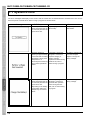
QBdirect Service Contents
Information
service (FAQ)
search
Offers detailed information on each product.
Download service
Offers downloads of repair modules for the latest BHT Series systems or
software, and sample programs.
E-mail inquiries
Product related queries can be sent in by e-mail.
* Please note that these privileges may be subject to change without prior notice.
− How to Register
Access the URL below and follow the instructions provided.
http://www.qbdirect.net/
Inquiries
− Technical Inquiries (QBdirect)
• BHT product programming method
• Product setup method, usage
• Other technical questions
Inquires relating to the above can be made at our exclusive Web site for registered users (QBdirect).
Access the link below to log on or register.
ii
BHT-700BB-CE/700BWB-CE/700BWBG-CE
About this Manual
•
Due to improvements and so on, the content of this manual may be subject to change without prior notice.
•
The reproduction or duplication of the whole or part of this manual is strictly prohibited without prior consent.
•
Every attempt has been made to ensure that the content of this manual is thorough and up to date, however, we
kindly ask that any questionable content, mistakes, or omissions be reported to DENSO WAVE.
•
The copyright for this User’s Manual belongs to DENSO WAVE INCORPORATED.
•
Lettering in the screens in this User’s Manual is a little different from that in the actual screens. File names used
are only for description purposes, and will therefore not display if files have not been set with the same names.
Manual Composition
This manual is made up of the following 9 chapters.
Chapter 1 Outline
Describes the BHT system and provides an overall outline of the BHT.
Chapter 2 BHT Preparation
Describes information required by the user and procedures that must be performed prior to
commencing operation.
Chapter 3 Basic Operation
Describes how to scan barcodes using the BHT, the backlight function, how to use the keypad, and
BHT data transmission.
Chapter 4 System Operation
Describes how to operate the desktop, Start menu and System Menu, and how to make wireless
network settings.
Chapter 5 Communication
Describes technical information on BHT connector communication, infrared communication, and
wireless communication, and provides details of Microsoft ActiveSync.
Chapter 6 Maintenance
Describes battery cartridge and memory back-up power source replacement, and daily procedures for
taking care of the BHT and CU/CH.
Chapter 7 Error Messages
Describes causes and countermeasures for error messages that display during BHT use.
Chapter 8 Specifications
Describes specifications for hardware, readable barcodes, and interfaces.
Chapter 9 Appendices
Describes the CU-700 Series (option) and provides details of the MicroSD card (option) insertion
procedure.
iii
Barcode Handy Terminal
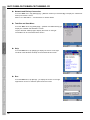
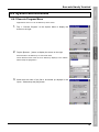
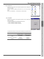
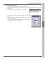
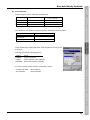
Viewing this Manual
− About the Bookmark
The PDF Bookmark function can be used to jump to the Contents page.
<Procedure>
(1) Click the “Bookmark” tab.
to search for the desired item.
(2) Click
(3) Click the item to be read.
(1) Click the “Bookmarks” tab.
(2) Click “+” to search for the desired item.
(3) Click the item to be read.
iv
BHT-700BB-CE/700BWB-CE/700BWBG-CE
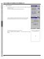
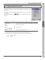
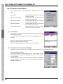
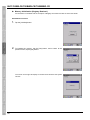
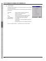
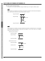
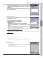
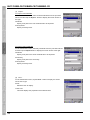
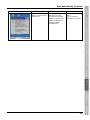
− Searching by Word
The PDF search function can be used to jump to the target page by entering words or characters related to the
item being searched.
(1) Click the Search icon. (Or select “Edit” – “Search”.)
(2) Enter the word(s) or character(s) to be searched for.
(3) Click [Search].
(1) Click the Search icon.
(2) Enter the search word(s)
or character(s).
(3) Click [Search].
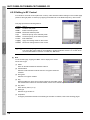
<Search Results Example>
v
Barcode Handy Terminal
Related Documentation
• BHT-700-CE API Reference Manual
• BHT-700-CE Class Library Reference Manual
• 2D Code Scanner/Barcode Scanner Keyboard Interface with BHT-CE kbifCE User’s Guide
vi
BHT-700BB-CE/700BWB-CE/700BWBG-CE
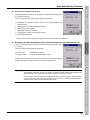
SAFETY PRECAUTIONS
Be sure to observe all these safety precautions.
Please READ through this manual carefully. It will enable you to use the BHT and CU correctly.
Always keep this manual nearby for speedy reference.
Strict observance of these warnings and cautions is a MUST for preventing accidents that could result in bodily injury
and substantial property damage. Make sure you fully understand all definitions of these terms and symbols given
below before you proceed to the text itself.
Alerts you to those conditions that could cause serious bodily injury or death if the instructions
are not followed correctly.
Alerts you to those conditions that could cause minor bodily injury or substantial property
damage if the instructions are not followed correctly.
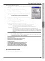
Meaning of Symbols
A triangle ( ) with a picture inside alerts you to a warning of danger. Here you see the warning for electrical
shock.
A diagonal line through a circle ( ) warns you of something you should not do; it may or may not have a picture
inside. Here you see a screwdriver inside the circle, meaning that you should not disassemble.
A black circle ( ) with a picture inside alerts you to something you MUST do. This example shows that you
MUST unplug the power cord.
vii
Barcode Handy Terminal
Handling the battery cartridge
• Never disassemble or heat the battery cartridge, nor put it into fire or water; doing so could cause
battery-rupture or leakage of battery fluid, resulting in a fire or bodily injury.
• Do not carry or store the battery cartridge together with metallic ball-point pens, necklaces, coins,
hairpins, etc.
Doing so could short-circuit the terminal pins, causing the batteries to rupture or the battery fluid to leak,
resulting in a fire or bodily injury.
• Avoid dropping the battery cartridge or letting it undergo any shock or impact.
Doing so could cause the batteries to break, generate heat, rupture or burn.
• Never charge the rechargeable battery cartridge where any inflammable gases may be emitted; doing
so could cause fire.
• Only use the dedicated charger for charging the rechargeable battery cartridge.
Using a different type of charger could cause battery-rupture or leakage of battery fluid and result in a
fire, bodily injury, or serious damage to property.
Handling the BHT
• Do not poke at the eyes with the stylus that comes with the BHT.
Handling the CU
• If smoke, abnormal odors or noises come from the CU, immediately unplug the AC adapter from the
wall socket or CU and contact your nearest dealer.
Failure to do so could cause fire or electrical shock.
• If foreign material or water gets into the CU, immediately unplug the AC adapter from the wall socket or
CU and contact your nearest dealer.
Failure to do so could cause fire or electrical shock.
• If you drop the CU so as to damage its housing, immediately unplug the AC adapter from the wall
socket or CU and contact your nearest dealer.
Failure to do so could cause fire or electrical shock.
• Never use the CU for charging anything other than the specified battery cartridges.
Doing so could cause heat, battery-rupture, or fire.
• Never bring any metals into contact with the output terminals.
Doing so could produce a large current through the CU, resulting in heat or fire, as well as damage to
the CU.
• Never use the CU on the line voltage other than the specified level.
Doing so could cause the CU to break or burn.
• Use the dedicated AC adapter only.
Failure to do so could result in fire.
• If the power cord of the AC adapter is damaged (e.g., exposed or broken lead wires), stop using it and
contact your nearest dealer.
Failure to do so could result in a fire or electrical shock.
viii
BHT-700BB-CE/700BWB-CE/700BWBG-CE
Handling the battery cartridge
• Charge batteries in temperature from 0°C to 40°C (32°F to 104°F).
• Never charge a wet or damp rechargeable battery cartridge.
Doing so could cause the batteries to break, generate heat, rupture or burn.
Handling the BHT
• If smoke, abnormal odors or noises come from the BHT, immediately turn off the power, pull out the
battery cartridge, and contact your nearest dealer.
Failure to do so could cause smoke or fire.
• If foreign material or water gets into the BHT, immediately turn off the power, pull out the battery
cartridge, and contact your nearest dealer.
Failure to do so could cause smoke or fire.
• If you drop the BHT so as to damage its housing, immediately turn off the power, pull out the battery
cartridge, and contact your nearest dealer.
Failure to do so could cause smoke or fire.
• Do not use batteries or power sources other than the specified ones; doing so could generate heat or
cause malfunction.
• When using the hand belt, exercise due care to avoid getting them caught in other objects or entangled
in rotating machinery.
Failure to do so could result in accident or injury.
• Never disassemble or modify the BHT; doing so could result in an accident such as break or fire.
Never disassemble
• Never put the BHT in places where there are excessively high temperatures, such as inside closed-up
automobiles, or in places exposed to direct sunlight.
Doing so could affect the housing or parts, resulting in a fire.
• Avoid using the BHT in extremely humid or dusty areas, or where there are drastic temperature
changes.
Moisture or dust will get into the BHT, resulting in malfunction, fire or electrical shock.
• In environments where static electricity can build into significant charges (e.g., if you wipe off the plastic
plate with a dry cloth), do not operate the BHT. Doing so will result in malfunction or machine failure.
• Do not apply excessive force when inserting or removing the rechargeable battery cartridge.
Doing so will result in damage.
• Tap the LCD only with the stylus that comes with the BHT.
Using the tip of a pen or any pointed object will result in a damaged or broken LCD.
• Put your palm of the hand through the handbelt.
If you put your arm through the handbelt, it can be broken.
ix
Barcode Handy Terminal
Handling the CU
• Never disassemble or modify the CU; doing so could result in an accident such as fire or malfunction.
• Never put the CU in places where there are excessively high temperatures, such as inside closed-up
automobiles, or in places exposed to direct sunlight.
Doing so could affect the housing or parts, resulting in a fire.
• Avoid using the CU in extremely humid or dusty areas, or where there are drastic temperature changes.
Moisture or dust will get into the CU, resulting in malfunction, fire or electrical shock.
• Never cover or wrap up the CU or AC adapter in a cloth or blanket.
Doing so could cause the unit to heat up inside, deforming its housing, resulting in a fire.
Always use the CU and AC adapter in a well-ventilated area.
• Do not place the CU anyplace where it may be subjected to oily smoke or steam, e.g., near a cooking
range or humidifier.
Doing so could result in a fire or electrical shock.
• Keep the power cord away from any heating equipment.
Failure to do so could melt the sheathing, resulting in a fire or electrical shock.
• Do not insert or drop foreign materials such as metals or anything inflammable through the openings or
vents into the CU.
Doing so could result in a fire or electrical shock.
• If you are not using the CU for a long time, be sure to unplug the AC adapter from the wall socket for
safety.
Failure to do so could result in a fire.
• When caring for the CU, unplug the AC adapter from the wall socket for safety.
Failure to do so could result in an electrical shock.
x
BHT-700BB-CE/700BWB-CE/700BWBG-CE
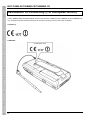
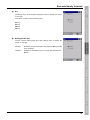
Declaration of Conformity (For European Union)
Hereby, DENSO WAVE INCORPORATED, declares that this BHT-700BB-CE, BHT-700BWB-CE, BHT-700BWBG-CE
is in compliance with the essential requirements and other relevant provisions of Directive 1999/5/EC.
CE marking:
LABELING:
For European Union
xi
Contents
Preface............................................................................................................................................... i
Customer Registration and Inquiries ................................................................................................. ii
About this Manual..............................................................................................................................iii
SAFETY PRECAUTIONS.................................................................................................................vii
Declaration of Conformity (For European Union ) ............................................................................ xi
Chapter 1 Outline......................................................................... 1
1.1 System Configuration.......................................................................................................... 2
1.1.1 Hardware Configuration ........................................................................................... 2
1.1.2 Software Configuration ............................................................................................. 3
1.2 Component Names and Functions...................................................................................... 4
1.2.1 BHT Front/Rear ........................................................................................................ 4
1.2.2 Keypad ..................................................................................................................... 8
1.2.3 BHT Screen............................................................................................................ 12
Chapter 2 BHT Preparation ....................................................... 15
2.1 “BHT Preparation” Procedure............................................................................................ 16
2.2 Loading and Charging the Battery Cartridge..................................................................... 16
2.2.1 Loading and Charging the Battery Cartridge .......................................................... 17
2.2.2 Battery Power Level Indicator................................................................................. 23
2.2.3 Battery Voltage Drop .............................................................................................. 23
2.3 Attaching the Stylus........................................................................................................... 24
2.3.1 Attaching the Stylus................................................................................................ 24
2.3.2 Holding the BHT ..................................................................................................... 24
2.3.3 Using the Stylus...................................................................................................... 25
2.3.4 Touch Screen Operation......................................................................................... 25
2.4 Initial Setup ....................................................................................................................... 26
2.5 Turning OFF the Power..................................................................................................... 27
2.5.1 Normal Power OFF ................................................................................................ 27
2.5.2 Turning the Power OFF after Registry Back-up...................................................... 27
2.5.3 Auto Power OFF..................................................................................................... 28
2.6 Resetting and Full Resetting ............................................................................................. 29
2.6.1 Reset...................................................................................................................... 29
2.6.2 Reset Method ......................................................................................................... 29
2.6.3 Full Reset ............................................................................................................... 29
xii
2.6.4 Full Reset Method .................................................................................................. 29
2.6.5 Memory Contents after Reset/Full Reset................................................................ 30
2.6.6 Applications Started Up when Performing a Reset/Full Reset................................ 30
Chapter 3 Basic Operation......................................................... 31
3.1 Scanning Barcodes ........................................................................................................... 32
3.2 Turning ON/OFF the Backlight .......................................................................................... 34
3.3 Using the Keypad.............................................................................................................. 36
3.3.1 Entering Numerical Data ........................................................................................ 36
3.3.2 Entering Alphabet Data .......................................................................................... 36
3.3.3 Entering Data using shift status .............................................................................. 37
3.3.4 Entering Data in function mode .............................................................................. 37
3.3.5 Using the Software Keyboard................................................................................. 37
3.4 Transmitting Data.............................................................................................................. 38
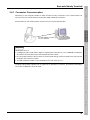
3.4.1 Connector Communication ..................................................................................... 39
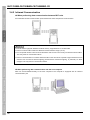
3.4.2 Infrared Communication ......................................................................................... 40
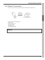
3.4.3 Bluetooth® Communication.................................................................................... 41
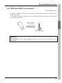
3.4.4 Wireless Communication........................................................................................ 42
3.4.5 GPRS and EDGE Communication ......................................................................... 43
Chapter 4 System Operation ..................................................... 45
4.1 Desktop............................................................................................................................. 46
4.2 Start Menu......................................................................................................................... 49
4.3 System Menu Outline........................................................................................................ 59
4.3.1 System Menu Structure .......................................................................................... 60
4.4 System Menu Details ........................................................................................................ 63
4.4.1 Execute Program Menu.......................................................................................... 63
4.4.2 Communication Menu ............................................................................................ 64
4.4.3 System Properties .................................................................................................. 75
4.4.4 HardTest Menu ....................................................................................................... 93
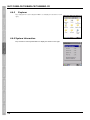
4.4.5 Explorer................................................................................................................ 102
4.4.6 System Information .............................................................................................. 102
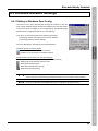
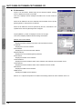
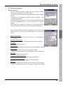
4.5 Wireless Network Settings .............................................................................................. 103
4.5.1 Editing in Windows Zero Config ........................................................................... 103
4.5.2 Editing in RF Control ............................................................................................ 108
xiii
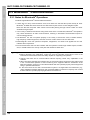
Chapter 5 Communication ....................................................... 113
5.1 Connector Communication.............................................................................................. 114
5.2 Infrared Communication.................................................................................................. 115
5.3 Bluetooth® Communication ............................................................................................ 116
5.3.1 Notes for Bluetooth® Operations ......................................................................... 116
5.3.2 Specifying Parameters ......................................................................................... 117
5.4 Wireless Communication ................................................................................................ 118
5.4.1 Usage Precautions ............................................................................................... 118
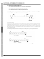
5.5 Basic Communication Specifications and Ymodem Communication .............................. 119
5.5.1 Basic Communication Specifications.................................................................... 119
5.5.2 Ymodem Communication ..................................................................................... 121
5.6 ActiveSync ...................................................................................................................... 122
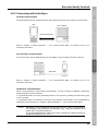
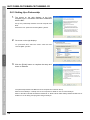
5.6.1 ActiveSync 4.5 Installation.................................................................................... 122
5.6.2 Connecting with ActiveSync ................................................................................. 123
5.6.3 Setting Up a Partnership ...................................................................................... 124
Chapter 6 Maintenance............................................................ 125
6.1 Replacing the Battery Cartridge ...................................................................................... 126
6.1.1 Battery Cartridge Service Life .............................................................................. 126
6.1.2 Battery Cartridge Replacement Method ............................................................... 126
6.2 Replacing the Back-up Battery........................................................................................ 129
6.3 Using the BHT after Long Periods................................................................................... 130
6.4 Daily Maintenance .......................................................................................................... 131
6.4.1 Proper Care of the BHT........................................................................................ 131
6.4.2 Proper Care of the CU/CH ................................................................................... 131
Chapter 7 Error Messages....................................................... 133
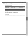
7.1 System Errors ................................................................................................................. 134
Chapter 8 Specifications .......................................................... 137
8.1 Specifications .................................................................................................................. 138
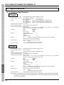
8.1.1 Hardware Specifications....................................................................................... 138
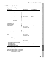
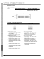
8.1.2 Barcode Specifications ......................................................................................... 139
8.1.3 Interface Specifications ........................................................................................ 141
xiv
Chapter 9 Appendices.............................................................. 143
9.1 CU-700 Functions ........................................................................................................... 144
9.2 Components and Functions ............................................................................................ 145
9.3 CU-700 Power Supply..................................................................................................... 147
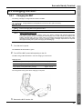
9.4 Communicating with the Host Computer......................................................................... 149
9.4.1 Interface Cable Connection .................................................................................. 149
9.4.2 Communication with the Host Computer .............................................................. 150
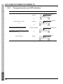
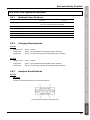
9.5 Charging the BHT ........................................................................................................... 151
9.5.1 Charging the BHT................................................................................................. 151
9.5.2 Charging Operation and LED Indicators............................................................... 152
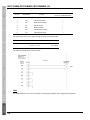
9.6 CU-700 Specifications..................................................................................................... 153
9.6.1 Hardware Specifications....................................................................................... 153
9.6.2 Charging Requirements ....................................................................................... 153
9.6.3 Interface Specifications ........................................................................................ 153
9.6.4 Interface Cable Connection .................................................................................. 156
9.7 Inserting the MicroSD Card............................................................................................. 157
9.8 Inserting the SIM Card .................................................................................................... 158
xv
BHT-700BB-CE/700BWB-CE/700BWBG-CE
Chapter 1
Outline
This chapter describes the BHT system and provides an overall outline of the BHT.
1.1
System Configuration ···················································································2
1.1.1 Hardware Configuration ···················································································2
1.1.2 Software Configuration·····················································································3
1.2 Component Names and Functions ·······························································4
1.2.1 BHT Front/Rear································································································4
1.2.2 Keypad ·············································································································8
1.2.3 BHT Screen····································································································12
BHT-700BB-CE/700BWB-CE/700BWBG-CE
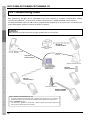
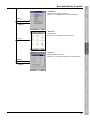
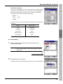
1.1 System Configuration
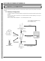
This section describes the hardware required for the barcode data collection system used by the BHT and the BHT
software.
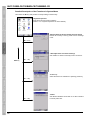
1.1.1 Hardware Configuration
In addition to the BHT, the following hardware is required for the barcode data collection system used by
the BHT.
Please note that certain components of the required hardware will differ depending on the type of
communication used.
Refer to "Chapter 3 Basic Preparation" – "3.4 Transmitting Data" for detail.
* BHT-700BWB-CE/700BWBG-CE only
** BHT-700BWBG-CE only
Ethernet
Wireless LAN access point
(option)
Wireless
communication*
Bluetooth®-enabled
devices (option)
Bluetooth®
communication
Infrared
communication
Host computer
BHT
GPRS and EDGE
communication**
Connector
communication
Wireless base station
CU-733 or CU-714
(option)
2
CU-733 : RS-232C or USB
CU-714 : Ethernet
Barcode Handy Terminal
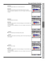
1.1.2 Software Configuration
[1]
BHT Operating System (OS)
Microsoft Windows CE 5.0
[2]
Application Program Development Environment
Refer to "BHT-700-CE API Reference Manual".
3
BHT-700BB-CE/700BWB-CE/700BWBG-CE
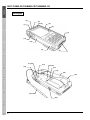
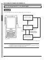
1.2 Component Names and Functions
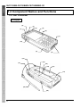
1.2.1 BHT Front/Rear
27-Keypad
(2)
(3)
(4)
(1)
(5)
(6)
(7)
(10)
(9)
(8)
(12)
(13)
(11)
(14)
(15)
(16)
(17)
(19)
(18)
4
Barcode Handy Terminal
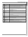
No.
Name
(1)
Beeper
(2)
Charge LED
(3)
Indicator LED
Function and Description
Illuminates in red during charging and turns green upon completion of charging.
Indicates the barcode read status.
Illuminates in blue when the BHT has successfully read a barcode.
(4)
(5)
Receiver
IEEE802.11a/b/g
Used to communicate with the wireless LAN access point.
built-in antenna
Do not cover this antenna section with metal-evaporated tape or by hand. Doing so may result in
communication failures.
(* Provided on the BHT-700BWB-CE only.)
(6)
Touch screen display (LCD)
Displays the characters and graphic patterns. Data may be entered by tapping the screen
directly with the stylus.
(7)
Microphone
(8)
Interface port
(9)
®
Bluetooth built-in antenna
USB and RS-232C interface port
®
Used to communicate with other Bluetooth -enabled devices.
Do not cover this antenna section with metal-evaporated tape or by hand. Doing so may result in
communication failures.
(10)
Trigger switch
Press when scanning a barcode.
(This key performs the same function as the Scan key.)
(11)
(12)
Reading window
Align the reading window with barcodes to perform barcode scanning.
(13)
Reset button
Refer to “Chapter 2 BHT Preparation” – “2.6 Resetting and Full Resetting”
(14)
Battery lock switch
Lock after inserting the battery cartridge.
Hand belt
Always put your hand through this belt to prevent the BHT from being dropped accidentally.
(15)
(16)
(17)
Rechargeable battery
Main BHT power source
cartridge
* The battery cartridge shown in the drawing is the BT-700L.
(18)
IrDA interface port
Used to exchange data/programs with the host computer or another BHT.
(19)
Stylus
Used to operate the touch screen.
5
BHT-700BB-CE/700BWB-CE/700BWBG-CE
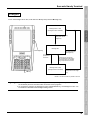
42-Keypad
(2)
(3)
(4)
(1)
(5)
(6)
(7)
(11)
(10)
(9)
(8)
(13)
(14)
(12)
(15)
(16)
(17)
(18)
(19)
(21)
(20)
6
Barcode Handy Terminal
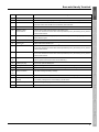
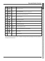
No.
Name
(1)
Beeper
(2)
Charge LED
(3)
Indicator LED
Function and Description
Illuminates in red during charging and turns green upon completion of charging.
Indicates the barcode read status.
Illuminates in blue when the BHT has successfully read a barcode.
(4)
(5)
Receiver
IEEE802.11a/b/g
Used to communicate with the wireless LAN access point.
built-in antenna
Do not cover this antenna section with metal-evaporated tape or by hand. Doing so may result in
communication failures.
(6)
Touch screen display (LCD)
Displays the characters and graphic patterns. Data may be entered by tapping the screen
directly with the stylus.
(7)
Microphone
(8)
Interface port
(9)
®
Bluetooth built-in antenna
USB and RS-232C interface port
®
Used to communicate with other Bluetooth -enabled devices.
Do not cover this antenna section with metal-evaporated tape or by hand. Doing so may result in
communication failures.
(10)
GPRS built-in antenna
Used to communicate with a wireless base station.
Do not cover this antenna section with metal-evaporated tape or by hand. Doing so may result in
communication failures.
(11)
Trigger switch
Press when scanning a barcode.
(This key performs the same function as the Scan key.)
(12)
(13)
Headset jack plug
Connect the optional headset jack.
(14)
Reading window
Align the reading window with barcodes to perform barcode scanning.
(15)
Reset button
Refer to “Chapter 2 BHT Preparation” – “2.6 Resetting and Full Resetting”
(16)
Battery lock switch
Lock after inserting the battery cartridge.
Hand belt
Always put your hand through this belt to prevent the BHT from being dropped accidentally.
(17)
(18)
(19)
Rechargeable battery
Main BHT power source
cartridge
* The battery cartridge shown in the drawing is the BT-700LL.
(20)
IrDA interface port
Used to exchange data/programs with the host computer or another BHT.
(21)
Stylus
Used to operate the touch screen.
7
BHT-700BB-CE/700BWB-CE/700BWBG-CE
1.2.2 Keypad
The BHT key functions can be set at user programs.
The diagram below shows an example of settings for each key function.
27-Keypad
(1)
(2)
(3)
(6)
(7)
(4)
(5)
(9)
(10)
(8)
(11)
(12)
(13)
(16)
(14)
(15)
(17)
(18)
No.
Key
Name
(1)
Power key
Turns the BHT power ON and OFF.
(2)
Tab key
Used to enter a tab character.
(3)
(4)
M1, M2, M3
magic keys
(5)
8
Function and Description
• The SF and ENT key functions can be assigned to these magic keys by making settings at
the SYSTEM MENU.
• Character strings can be assigned at user programs.
* Refer to “Chapter 4 System Operation” for details on how to operate the SYSTEM MENU.
(6)
Trigger
Press to scan barcodes.
(7)
switches
(This key performs the same function as the Scan key.)
Barcode Handy Terminal
No.
Key
Name
Function and Description
(8)
Function keys
(9)
Scan key
(10)
Cursor keys
Used to move the cursor and select menus.
(11)
Escape keys
Cancels the operation.
(12)
Backspace key
Moves back one character.
(13)
Shift key
(14)
(15)
Function mode
key
Alphabetical
mode key
Used to select functions.
Press to scan barcodes.
(This key performs the same function as a Trigger switch.)
Used in combination with other keys such as the numerical keys or power key for special
input procedures.
Switches to Function mode.
Switches to alphabet entry mode.
(16)
Enter key
Press to finalize entered data or execute operations.
(17)
Space key
Enters a space.
(18)
Numerical
keys
Used to enter data.
(6), (7) and (9) have an OR connection. The BHT will recognize that the [SCAN] key has been pressed by
pressing any one of these keys.
9
BHT-700BB-CE/700BWB-CE/700BWBG-CE
42-Keypad
(1)
(2)
(3)
(6)
(7)
(4)
(5)
(9)
(10)
(8)
(11)
(17)
(18)
(12)
(13)
(16)
(15)
(14)
No.
Key
Name
(1)
Power key
Turns the BHT power ON and OFF.
(2)
Tab key
Used to enter a tab character.
(3)
(4)
M1, M2, M3
magic keys
(5)
10
Function and Description
• The SF and ENT key functions can be assigned to these magic keys by making settings at
the SYSTEM MENU.
• Character strings can be assigned at user programs.
* Refer to “Chapter 4 System Operation” for details on how to operate the SYSTEM MENU.
(6)
Trigger
• Press to scan barcodes.
(7)
switches
(This key performs the same function as the Scan key.)
Barcode Handy Terminal
No.
Key
Name
(8)
Function keys
(9)
Scan key
(10)
Cursor keys
(11)
(12)
(13)
Alphabetical
keys
Function mode
key
Numerical
mode key
Function and Description
Used to select functions.
Press to scan barcodes.
(This key performs the same function as a Trigger switch.)
Used to move the cursor and select menus.
Used to enter data.
Switches to Function mode.
Switches to numeric entry mode.
(14)
Backspace key
Moves back one character.
(15)
Space key
Enters a space.
(16)
Escape keys
Cancels the operation.
(17)
Shift key
(18)
Enter key
Used in combination with other keys such as the numerical keys or power key for special
input procedures.
Press to finalize entered data or execute operations.
(6), (7) and (9) have an OR connection. The BHT will recognize that the [SCAN] key has been pressed by
pressing any one of these keys.
11
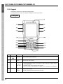
BHT-700BB-CE/700BWB-CE/700BWBG-CE
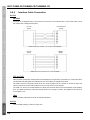
1.2.3 BHT Screen
Depending on user settings and so on, the Windows desktop in the screens in this Operator’s Guide may
differ a little from that in the actual BHT screen.
Note: The taskbar may also be a little different from that in the actual screens.
Indicates the current battery power level.
Indicates the wired LAN with the CU-714 connection status.
: The BHT is connected to a wired network.
: The BHT is disconnected to a wired network.
Indicates the wireless connection status.
: The BHT is connected to a wireless network.
: The BHT is not connected to a wireless network.
Indicates the wireless device open status and radio field intensity.
: Displays when the wireless device is open.
→
Strong
→
→
: Indicates the radio field intensity by the number of bars.
Weak
®
Indicates the Bluetooth power status.
: Appears when the Bluetooth® device is powered on. (Blue)
: Appears when the Bluetooth® device is powered off. (Grey)
(This icon does not dislay by default, but can be displayed by changing the setting at the System Menu or user
programs.)
Displays when the
key is pressed and the keys are in the shift status.
Displays when the
key is pressed and the keys are in the function status.
Displays when the BHT is communicating with the computer via Microsoft ActiveSync.
Displays when in numerical entry mode.(42-keypad only)
Displays when in alphabet entry mode. (27-keypad only)
(The entry mode can be changed by pressing the ALP key.)
Pressing a numerical key when in alphabet entry mode displays the letter assigned to that key in this ALP
window.
Refer to the BHT-700-CE Class Library Reference Manual “Chapter 9 Keyboard ” for the input character details
while in the ALP mode.
Tap this icon while an application is running to display the desktop. Tap again to return the original application
execution screen.
12
Barcode Handy Terminal
Indicates the software keyboard status.
(Tap this icon to display/hide the software keyboard, or switch the keyboard status ON/OFF.)
: Displays when ON.
: Displays when OFF.
Displays when the CPU switches to standby.
(This icon does not dislay when standby status by default, but can be displayed by changing the setting at the
System Menu or user programs.)
Displays when Caps Lock is pressed at the software keyboard.
− Note −
To minimize power consumption, the BHT automatically switches to standby mode after it has
not been operated for a specified period*.
In standby mode, the touch screen is not refreshed, and as a result, icons in the taskbar may
not be displayed or refreshed, and the calendar clock may not display the correct date or time.
* This time can be set by the user, with the default setting being one second. The time until the
BHT switches to standby mode can be updated at the System Menu (Refer to “Chapter 4
System Operation”.) or by creating user programs. Refer to the "BHT-700-CE API
Reference Manual" or "BHT-700-CE Class Library Reference Manual” for details of the user
program creation method.
13
BHT-700BB-CE/700BWB-CE/700BWBG-CE
14
BHT-700BB-CE/700BWB-CE/700BWBG-CE
Chapter 2
BHT Preparation
Describes information required by the user and procedures that must be
performed prior to commencing operation.
2.1
2.2
2.3
2.4
2.5
2.6
“BHT Preparation” Procedure ·····································································16
Loading and Charging the Battery Cartridge ··············································16
2.2.1 Loading and Charging the Battery Cartridge ·················································17
2.2.2 Battery Power Level Indicator ········································································23
2.2.3 Battery Voltage Drop ······················································································23
Attaching the Stylus ····················································································24
2.3.1 Attaching the Stylus························································································24
2.3.2 Holding the BHT·····························································································24
2.3.3 Using the Stylus ·····························································································25
2.3.4 Touch Screen Operation ················································································25
Initial Setup·································································································26
Turning OFF the Power ··············································································27
2.5.1 Normal Power OFF ························································································27
2.5.2 Turning the Power OFF after Registry Back-up·············································27
2.5.3 Auto Power OFF ····························································································28
Resetting and Full Resetting·······································································29
2.6.1 Reset ··············································································································29
2.6.2 Reset Method·································································································29
2.6.3 Full Reset ·······································································································29
2.6.4 Full Reset Method ··························································································29
2.6.5 Memory Contents after Reset/Full Reset·······················································30
2.6.6 Applications Started Up when Performing a Reset/Full Reset ······················30
BHT-700BB-CE/700BWB-CE/700BWBG-CE
2.1 “BHT Preparation” Procedure
Follow the steps below to prepare the BHT.
2.2
Loading and Charging the Battery
Cartridge(Page 16)
First load and charge the battery cartridge.
2.3
Attaching the Stylus (Page 23)
Attach the stylus to prevent it from being lost.
2.4
Initial Setup
Calibrate the touch screen and set the calendar clock
when the power is turned ON for the first time.
(Page 25)
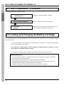
2.2 Loading and Charging the Battery Cartridge
The battery cartridge is not charged when purchased and should therefore be charged prior to use.
The chargers that can be use with the BHT are the communication units (CU-733, CU-714) and battery chargers
(CH-751, CH-704).
* The CH-704 charger is used for charging individual batteries, and the CH-751 is a stand-type (same type
as CU (communication unit)) charger.
The charge time is approximately 3 hours (standard rechargeable battery cartridge) or 6 hours
(large-capacity rechargeable battery cartridge).
An only slightly discharged battery cartridge should take less time to become fully charged.
Charging Precautions
• Do not touch the BHT, battery, or charger terminals by hand or stain them. Doing so could result
in a contact failure or prevent charging.
• Never charge the battery near fire or in a high-temperature environment.
High-temperatures may activate the charger’s protective device, preventing charging, and lead
to protective device damage, overheating, blowout or combustion.
• Terminate charging if not completed even after the specified time has elapsed.
16
Barcode Handy Terminal
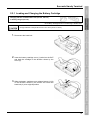
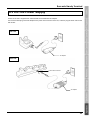
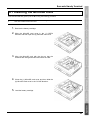
2.2.1 Loading and Charging the Battery Cartridge
Charging with the communication unit (CU-733, CU-714)
or battery charger (CH-751)
* The battery cartridge shown in the drawing is the BT-700L.
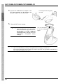
• Charge batteries in temperature from 0°C to 40°C (32°F to 104°F).
1. Disconnect the hand belt.
2. Insert the battery cartridge cover (1) tabs into the BHT
and load the cartridge in the direction shown by the
arrow (2).
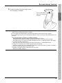
3. Slide the battery cartridge cover release buttons (1)/(2)
in the direction shown by the arrows and return the
hand belt (3) to its original position.
17
BHT-700BB-CE/700BWB-CE/700BWBG-CE
4. Connect the dedicated AC adapter to the
DC input connector on the charger and
plug the adapter into the wall socket.
5.
The charger Power LED (green)
turns ON.
Place the BHT on the charger.
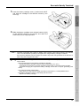
− Point −
− Note −
After placing the BHT on the charger
when using the BHT for the first time or
when left unused for long periods of time,
do not remove from the charger for
approximately
3
hours
(standard
rechargeable battery cartridge) or 6 hours
(large-capacity
rechargeable
battery
cartridge).
Red LED ON
The LED illuminates
in red and charging
begins.
The BHT is equipped with a back-up battery used to back-up the internal memory and calender
clock. The internal back-up battery is charged first when charging is commenced.
Do not remove the BHT from the charger for at least 2 days when using the BHT for the first time or
when using after long periods of time.
18
Barcode Handy Terminal
6. The BHT indicator LED will change to green
Green LED ON
when charging is complete.
The LED illuminates in
green when charging is
complete.
− Point −
Charging takes approximately 3 hours (standard rechargeable battery cartridge) or 6 hours
(large-capacity rechargeable battery cartridge).
An only slightly discharged battery cartridge should take this time to become fully charged.
The indicator LED flashing in red indicates the following causes. The proper action stated below must
be taken.
・Abnormal temperature of the battery cartridge is detected.
・Charge the battery cartridge under the proper temperature (0℃~40℃)
・Avoid places where there are objects generating heat nearby or exposed to direct sunlight.
・Terminate charging and replace the battery cartridge if there are no objects generating heat nearby.
・The charge terminals contact failure
・Wipe any dirt or dust from the charge terminals as described in “6.4 Daily Maintenance”.
・Charging is not completed even after the specified time has elapsed.
・Terminate charging and use a dedicated AC adapter to charge the battery cartridge if the battery
cartridge is charging through an unpowered USB.
・The battery cartridge is broken or the battery life has ended.
・Replace the battery cartridge.
19
BHT-700BB-CE/700BWB-CE/700BWBG-CE
Charging with the battery charger (CH-704)
* The battery cartridge shown in the drawing is the BT-700LL.
• Charge batteries in temperature from 0°C to 40°C (32°F to 104°F).
1. Check the battery cartridge terminals
and insert the cartridge.
2. Connect the power cable to the CH-704 and
connect the plug to a commercial AC power
source (100 V AC).
3. The red LED flashes slowly (1 second ON,
1 second OFF) when charging is complete.
− Point −
Charging takes approximately 3 hours
(standard
rechargeable
battery
cartridge) or 6 hours (large-capacity
rechargeable battery cartridge).
An only slightly discharged battery
cartridge should take this time to
become fully charged.
4. Disconnect the hand belt.
20
Barcode Handy Terminal
5. Insert the battery cartridge cover (1) tabs into the BHT
and load the cartridge in the direction shown by the
arrow (2).
6. Slide the battery cartridge cover release buttons (1)/(2)
in the direction shown by the arrows and return the
hand belt (3) to its original position.
− Note −
The BHT is equipped with a back-up battery used to back-up the internal memory and calender
clock. The internal back-up battery is charged first a charged battery cartridge is inserted.
Do not remove the BHT from the charger for at least 2 days when using the BHT for the first time or
when using after long periods of time.
− Point −
The indicator LED flashing in red indicates the following causes. The proper action stated below
must be taken.
・Abnormal temperature of the battery cartridge is detected.
・Charge the battery cartridge under the proper temperature (0℃~40℃)
・Avoid places where there are objects generating heat nearby or exposed to direct sunlight.
・Terminate charging and replace the battery cartridge if there are no objects generating heat
nearby.
・The charge terminals contact failure
・Wipe any dirt or dust from the charge terminals as described in “6.4 Daily Maintenance”.
・The battery cartridge is broken or the battery life has ended.
・Replace the battery cartridge.
21
BHT-700BB-CE/700BWB-CE/700BWBG-CE
Mishandling of the charger may result in charger overheating, smoke generation, blowout or
combustion. Please read the following items prior to use.
Never disassemble or modify the battery cartridge.
Never connect the battery cartridge (+) and (-) terminals with a metal object such as a piece of
wire.
Never carry or store the battery cartridge together with metallic necklaces, hairpins and so on.
Never expose the battery cartridge to fire or apply heat.
Never use or leave the battery cartridge in the vicinity of high-temperature locations (60° C or
higher) such as a fire or stove.
Never place the battery cartridge into or soak it in water or seawater.
Never charge the battery cartridge in the vicinity of fire or under a scorching sun.
Never hammer nails into the battery cartridge, hit it with a hammer, or trample on it.
Never apply strong impact to or throw the battery cartridge.
Never use significantly damaged or deformed battery cartridges.
Never apply solder directly to the battery cartridge.
If battery fluid leaked from the battery cartridge gets into the eyes or comes into contact with the
skin, wash thoroughly with clean water such as tap water without rubbing, and obtain medical
treatment immediately. Failure to do so will result in eye or skin injuries.
Mishandling of the charger may result in charger overheating, smoke generation, blowout or
combustion. Please read the following item prior to use.
Terminate charging if not completed even after the specified time has elapsed.
− Note −
The BHT is equipped with a back-up battery used to back-up the internal memory and calendar
clock when the battery cartridge is removed or the battery voltage falls below the stipulated
level.
It is therefore necessary to charge the internal back-up battery when using the BHT for the first
time or when left unused for long periods of time.
The back-up battery is charged automatically when a fully-charged battery cartridge is loaded.
To ensure that the back-up battery is fully charged, do not remove the battery cartridge for at
least 2 days when using the BHT for the first time or when using after long periods of time.
Refer to “Chapter 6 Maintenance” – “6.3 Using the BHT after Long Periods” for details of
handling the BHT after long periods of time.
Avoid storing the battery cartridge in high-temperature locations. The battery capacity may
decrease.
Do not touch the BHT, battery, or charger terminals by hand or stain them. Doing so may result
in a BHT operation defect or battery cartridge charging failure. It is recommended that dirt on
the battery cartridge terminals or BHT battery terminals be periodically wiped with a soft, dry
cloth.
22
Barcode Handy Terminal
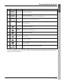
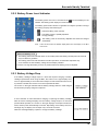
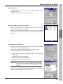
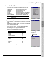
2.2.2 Battery Power Level Indicator
The battery power level can be checked at the
taskbar. The battery power displays in three levels.
icon that displays in the
The battery power level indicator is a guideline to notify the operator to charge
the battery promptly when discharged.
: Sufficient battery power remains.
: The battery power is partially depleted.
Charge promptly.
: The battery power is almost fully depleted and should be charged
immediately.
Note: There are times when the taskbar display differs from the display on the BHT
LCD screen.
About the Battery Level
• The battery power level indicator does not accurately reflect the battery residual power and should
only be used as a guideline.
• The battery power level will fluctuate due to BHT operation, and therefore disparities may
occur between the actual battery voltage and the display indicator.
• Ensure to charge the battery as soon as possible before the battery power is depleted.
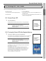
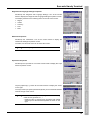
2.2.3 Battery Voltage Drop
If the battery cartridge voltage drops to a level that requires charging or battery
cartridge replacement while using the BHT, the screen on the right displays only
once for approximately 2 seconds and the beeper sounds three times when a key
is pressed. The BHT then returns to its normal operational status.
The screen on the right indicates that the battery cartridge will soon need charged
and should be promptly charged or replaced.
If use of the BHT is continued without charging or replacing the battery cartridge
after the above message displays and the battery voltage drops to a level that
prevents BHT operation, the screen on the right displays, the beeper sounds five
times, and the power automatically turns OFF. Depending on the battery level, this
message may not display or the beeper may not sound five times.
When this message displays, replace or charge the battery cartridge.
23
BHT-700BB-CE/700BWB-CE/700BWBG-CE
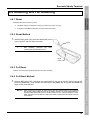
2.3 Attaching the Stylus
Attach the stylus to prevent it from being lost.
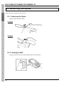
2.3.1 Attaching the Stylus
Attach the stylus as shown below.
27-Keypad
42-Keypad
2.3.2 Holding the BHT
Insert your hand into the hand belt and hold the BHT as shown below.
24
Barcode Handy Terminal
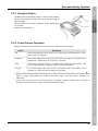
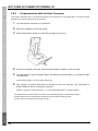
2.3.3 Using the Stylus
The BHT liquid crystal display (LCD) is a touch screen. Buttons,
menus and so displayed on the screen can be selected using the
stylus provided.
Always perform touch screen calibration before operating the
touch screen.
(Refer to “2.4 Initial Setup”.)
2.3.4 Touch Screen Operation
Select the LCD touch screen buttons and menus and so on using the stylus provided.
Action
Description
Tap
This involves tapping the touch screen once. This function is the equivalent of a “click”
with a mouse on a computer.
Double-tap
This involves tapping the touch screen twice in quick succession. This function is the
equivalent of a “double-click” with a mouse on a computer.
Drag
This involves moving the stylus to an object while pressing the touch screen. This
function is the equivalent of “dragging” with the mouse on a computer.
Long-tap
This involves tapping the touch screen for several seconds. This function is the
equivalent of a "right-click" with the mouse on a computer.
• Always use the stylus provided to operate the touch screen. Never use fingernails or any pointed or hard
objects, or apply strong pressure or impact to the touch screen. This may result in damage or a
malfunction.
• If dirty, clean the touch screen and stylus tip prior to operation. Failure to observe this may result in
scratches to the LCD screen or hinder smooth movement of the stylus.
25
BHT-700BB-CE/700BWB-CE/700BWBG-CE
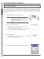
2.4 Initial Setup
It is necessary to perform touch screen calibration and set the date and time when turning ON the BHT power for the
first time. Press the power key to turn ON the BHT power. The calibration screen should then display. If the calibration
screen does not display, first perform a “full reset”. Refer to “2.6 Resetting and Full Resetting” for details of the full
reset method.
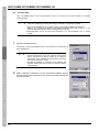
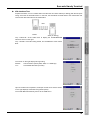
1. Press the power key to turn ON the BHT power.
− Point −
Power key
It may take time to display the screen after pressing the
power key, but it is not malfunction of the BHT.
Therefore, do not keep pressing the power key
than needed or press it hard.
more
Doing so may cause breakage or malfunction of the
power key.
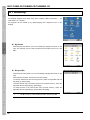
2. The screen on the right displays.
Tap the center of the “+” with the stylus for approximately 1 second.
Tap the center of the “+” each time it moves.
(The “+” mark moves from the center of the screen to the upper left, lower
left, lower right and upper right, making a total of 5 positions.)
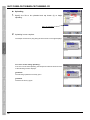
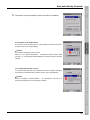
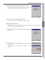
3. Press the ENT key.
Press the ENT key or tap the screen to complete touch screen calibration
and display the data and time setting screen.
4.
26
Set the date, time and time zone and then tap the OK button.
Barcode Handy Terminal
2.5 Turning OFF the Power
Use one of the following three methods to turn OFF the BHT power.
Normal power OFF
Turning the power OFF after registry back-up
Auto power OFF
→ Press the power key.
→ Hold down the SF key and press the power key for 3
seconds or more.
→ The power turns OFF automatically when the BHT is not
used for a set length of time.
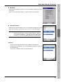
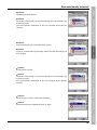
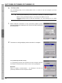
2.5.1 Normal Power OFF
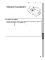
1.
Press the power key.
The BHT power turns OFF after the screen on the right displays.
− Point −
Do not remove the battery cartridge while the
message on the right is displayed.
Failure to observe this may result in data stored in
the BHT being lost.
2.5.2 Turning the Power OFF after Registry Back-up
1.
Hold down the SF key and press the power key.
The message on the right displays and registry back-up is commenced.
The power turns OFF automatically when the back-up is complete.
− Point −
Do not remove the battery cartridge while the
message on the right is displayed.
Failure to observe this may result in data stored in
the BHT being lost.
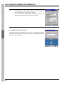
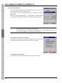
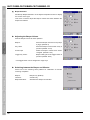
The Registry is an area in which settings information required for
BHT operation is recorded.
If the Registry is lost, it is automatically restored by the OS.
The error message on the right displays if the OS fails to restore
the Registry (because the Registry has not been backed up).
Refer to “Chapter 4 System Operation” for details of how to
return the Registry to its default status.
27
BHT-700BB-CE/700BWB-CE/700BWBG-CE
2.5.3 Auto Power OFF
The power turns OFF automatically when the BHT is not used for the length of time set at the user
program.
The default time is set to 3 minutes when the BHT is shipped from the factory.
− Point −
Do not remove the battery cartridge while Auto Power OFF is processing.
Failure to observe this may result in data stored in the BHT being lost.
* Refer to “Chapter 4 System Operation” for details of auto power OFF.
28
Barcode Handy Terminal
2.6 Resetting and Full Resetting
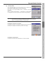
2.6.1 Reset
Reset the BHT in the following cases.
•
The BHT makes no response to entry from the touch screen or keys.
•
Programs in the BHT malfunction for some unknown reason.
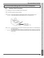
2.6.2 Reset Method
1. With the BHT power ON, press the reset button on the
rear of the BHT with the stylus provided.
Stylus
− Point −
Data stored as a file will not be lost even
after resetting. However, any data
currently being edited will be lost.
Reset
button
2.6.3 Full Reset
Perform a full reset if the problem persists even after resetting.
2.6.4 Full Reset Method
1. With the BHT power OFF, hold down the reset button on the rear of the BHT with the stylus and
press the power key. Then release the reset button and power key and press the power key
again to fully reset the BHT.
− Point −
When performing full reset, all data including files and settings stored in the RAM will
also be lost and the RAM will revert to the factory default. It is recommended that any
important data be backed up to the “FLASH” folder or to the computer before full reset.
When the BHT turns ON after the data in the RAM is deleted, the BHT starts from the
“Initial Setup”.
29
BHT-700BB-CE/700BWB-CE/700BWBG-CE
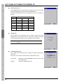
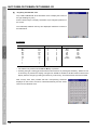
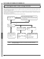
2.6.5 Memory Contents after Reset/Full Reset
Reset
Full Reset
Data in the “FLASH” folder
Data retained
Data retained
Data in other folders
Data retained
Data erased
Contents of the Registry
Data retained
Data erased
Data being edited
Data erased
Data erased
(Note)
(Note) If the Registry has been backed up (Refer to “2.5 Turning OFF the Power”.), the backed up
Registry will be used.
2.6.6 Applications Started Up when Performing a Reset/Full Reset
Any executable files (XXXXXX.exe) in the “FLASH\StartUp” folder will be automatically started up when
rebooting the BHT following a reset/full reset.
30
BHT-700BB-CE/700BWB-CE/700BWBG-CE
Chapter 3
Basic Operation
This chapter describes how to scan barcodes using the BHT, the backlight
function, how to use the keypad, and BHT data transmission.
3.1
3.2
3.3
Scanning Barcodes ····················································································32
Turning ON/OFF the Backlight ···································································34
Using the Keypad ·······················································································36
3.3.1 Entering Numerical Data················································································36
3.3.2 Entering Alphabet Data ··················································································36
3.3.3 Entering Data using shift status ·····································································37
3.3.4 Entering Data in function mode······································································37
3.3.5 Using the Software Keyboard ········································································37
3.4 Transmitting Data ·······················································································38
3.4.1 Connector Communication ············································································39
3.4.2 Infrared Communication·················································································40
3.4.3 Bluetooth® Communication ············································································41
3.4.4 Wireless Communication ···············································································42
3.4.5 GPRS and EDGE Communication ································································43
BHT-700BB-CE/700BWB-CE/700BWBG-CE
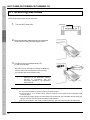
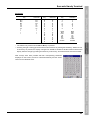
3.1 Scanning Barcodes
Follow the procedure below to scan barcodes.
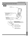
1.
Turn the BHT power ON.
Power key
2. Bring the barcode reading window to a barcode
to be scanned, and press the trigger switch.
3. The BHT turns on the illumination LED
to scan the barcode.
Barcodes can be read also by pressing the Scan key.
When the BHT has read the barcode successfully,
the indicator LED will illuminate in blue.
− Point −
− Note −
Blue LED ON
The barcode scanning method may differ
depending on the application. Perform
scanning in accordance with the
instructions provided in the application
User’s Manual.
If required, clean dirty labels before scanning.
It may not be possible to perform scanning in direct sunlight.
If the barcode is on a curved surface, perform scanning in the center of the illumination LED
emission range.
If the barcode reading window is pulled away from the barcode, the scannable barcode range will
become narrower than that of the illumination LED emission.
Do not use the BHT in the vicinity of radio equipment. This may cause the BHT to malfunction.
32
Barcode Handy Terminal
− Note −
By using the “KbifCE” utility software, codes read by the BHT can be converted into keypad data
to be transmitted to an application program. The utility software can be downloaded from the
DENSO WAVE Web site (http://www.denso-wave.com/). For further details, refer to the “2D Code
Scanner/Barcode Scanner Keyboard Interface with BHT-CE kbifCE User's Guide“ provided with
the software.
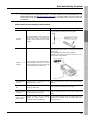
When unable to successfully read barcodes…
Cause
Countermeasure
Change the BHT scanning angle and try again.
When the illumination LED is focused on
the printed surface of the barcode from
directly above, there are times when
scanning is unsuccessful due to specular
reflection.
Specular
reflection
Move the BHT slowly toward or away from the barcode
and try again.
The illumination LED range is only a guideline.
Barcodes can be read at a maximum distance of 70 cm
from the BHT reading window.
Distance
barcode
from
Scanning may be unsuccessful if the BHT
reading window is too close to or too far
from the barcode, even when the barcode
is within the illumination LED range.
Barcode surface
curvature
Scanning may be unsuccessful if the
barcode surface is curved.
Scan the barcode at the center of the barcode reading
window.
Barcode surface
dirt
Scanning may be unsuccessful if the
barcode surface is dirty.
Wipe the dirt from the barcode and try again.
Barcode reading
window dirt
Scanning may be unsuccessful if the
barcode reading window is dirty.
Blow any dust away with an airbrush, and then gently
wipe the reading window with a cotton swab or similar soft
object.
Direct sunlight,
ambient light
Barcode scanning may be adversely
affected by direct sunlight or the
brightness of the surrounding light.
Perform barcode scanning away from direct sunlight. Try
adjusting the brightness of the surrounding light when
scanning indoors.
33
BHT-700BB-CE/700BWB-CE/700BWBG-CE
3.2 Turning ON/OFF the Backlight
27-Keypad
To turn the backlight ON or OFF, hold down the SF key and press the M3 magic key.
Backlight OFF or dim
(backlight function disabled)
Hold down the SF key
and press the M3
magic key.
Backlight ON
M3 magic key
Hold down the SF
key and press the
M3 magic key.
If no key is
pressed for 3
seconds.*
Press any key (except for
the simultaneous depression
of the M3 magic key and SF
key) or tap the touch screen.
Backlight OFF or dim
(backlight function enabled)
SF key
Hold down the SF key
and press the M3 magic
key.
* Under 1 minute if the BHT is placed on the CU.
− Point −
The backlight function enable/disable key (simultaneous pressing of SF key and M3 magic key
set as default) and time until auto OFF can be set at user programs.
As opposed to pressing the backlight function enable/disable key, the backlight function can
be enabled or disabled at the Backlight settings menu.
34
Barcode Handy Terminal
42-Keypad
To turn the backlight ON or OFF, hold down the SF key and press the M3 magic key.
Backlight OFF or dim
(backlight function disabled)
Hold down the SF key
and press the M3
magic key.
Backlight ON
M3 magic key
Hold down the SF
key and press the
M3 magic key.
If no key is
pressed for 3
seconds.*
Press any key (except for
the simultaneous depression
of the M3 magic key and SF
key) or tap the touch screen.
Backlight OFF or dim
(backlight function enabled)
SF key
Hold down the SF key
and press the M3 magic
key.
* Under 1 minute if the BHT is placed on the CU.
− Point −
The backlight function enable/disable key (simultaneous pressing of SF key and M3 magic key
set as default) and time until auto OFF can be set at user programs.
As opposed to pressing the backlight function enable/disable key, the backlight function can
be enabled or disabled at the Backlight settings menu.
35
BHT-700BB-CE/700BWB-CE/700BWBG-CE
3.3 Using the Keypad
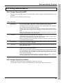
3.3.1 Entering Numerical Data
27-Keypad
The default setting is numeric entry mode, enabling numbers written on the left of the top of numeric keys to
be entered.
To enter “120” for example, press the “1”, “2” and “0” keys sequentially.
If the wrong number is incorrectly entered, press the BS key to delete the number and then reenter the
correct number.
42-Keypad
Press the NUM key to switch to numeric entry mode.
Numbers or symbols written on the right of the top of alphabet keys can be entered.
Incorrectly entered numbers or symbols can be deleted with the BS key.
Press the NUM key again to return to alphabet entry mode.
It is also possible to switch to alphabet entry mode at the program. Refer to the “BHT-700-CE API Reference
Manual" or "BHT-700-CE Class Library Reference Manual" for further details.
3.3.2 Entering Alphabet Data
27-Keypad
The 27-Keypad is equipped with two alphabet entry methods - “alphabet entry mode 1” and “alphabet entry
mode 2”.
Press the AL key to switch to alphabet entry mode 1.
Press the AL key again to switch to alphabet entry mode 2.
Press the AL key once again to return to numeric entry mode.
Numeric entry mode
AL key
Alphabet entry mode 1
Alphabet entry mode 2
AL key
In the same manner as that for alphabet character entry with a cellular phone, alphabet characters can be
entered using the numerical keys.
In alphabet entry mode 1, press a numerical key to display the alphabet character assigned to that key in the
ALP window.
(Refer to “Chapter 1 Outline” – “1.2.3 BHT Screen”.) and then press the ENT key to set that character.
In alphabet entry mode 2, by pressing the same key repeatedly, characters display not in the ALP window,
but in order at the cursor position.
The cursor position will shift if a different key is pressed.
42-Keypad
The default setting is alphabet entry mode, enabling alphabet characters written on the left of the top of
alphabet keys to be entered.
Incorrectly entered characters can be deleted with the BS key.
It is also possible to switch to alphabet entry mode at the program. Refer to the “BHT-700-CE API Reference
Manual" or "BHT-700-CE Class Library Reference Manual" for further details.
36
Barcode Handy Terminal
3.3.3 Entering Data using shift status
Press the [SF] key to switch to the shift status which enables the purple character keys.
For example, while holding down the [SF] key, pressing the purple [2] key enters the “@”.
There are two [SF] key modes –-“Nonlock mode” and “Onetime mode”.
“Nonlock mode” enables the shift status only while the [SF] key is held down.
“Onetime mode” enables the shift status for one key after pressing the [SF] key in addition to enabling the
shift status only while the [SF] key is held down.
The default setting is “Nonlock mode”.
The [SF] key mode can be switched in “System Properties”.
Refer to “4.4 System Menu Details – 4.4.3 System Properties – [6] key” for further details.
It is also possible to change the sift status with the program.
Refer to the “BHT-700-CE API Reference Manual” or “BHT-700 CE Class Library Reference Manual” for
further details.
3.3.4 Entering Data in function mode
The [FN] key switches to the function mode which enables the green character keys.
For example, pressing the [F1] key in function mode enters the “[F5]”.
By pressing the [FN] key again, function mode will be terminated.
It is also possible to change the function mode with the program.
Refer to the “BHT-700-CE API Reference Manual” or “BHT-700 CE Class Library Reference Manual” for
further details.
3.3.5 Using the Software Keyboard
Tap the software keyboard status icon in the taskbar to display/hide the software keyboard.
Similarly, the software keyboard is displayed by pressing the M2 key while holding down the SF key.
Software keyboard
Software keyboard status icon
Data can be entered by tapping the keys on the software keyboard.
37
BHT-700BB-CE/700BWB-CE/700BWBG-CE
3.4 Transmitting Data
Data gathered by the BHT can be transmitted to the host computer by connector communication, infrared
communication, Bluetooth® communication, wireless communication* or GPRS and EDGE communication**.
The data transmission method and BHT setting method will differ depending on the system used, and therefore the
system administrator should be contacted for details of operation.
Request
Data gathered by the BHT should be promptly uploaded to the host computer.
®
®
Bluetooth
communication
Bluetooth -enabled
devices
CU-733 : RS232C or USB
CU-714 : Ethernet
Ethernet
Connector
communication
Wireless LAN access point
Wireless
communication*
Host computer
Infrared
communication
Wireless base station
GPRS and EDGE
communication**
* BHT-700BWB-CE/700BWBG-CE only
To perform wireless communication with a wireless LAN access point, it is necessary to
configure the wireless local area network (wireless LAN) at the BHT and access point.
** BHT-700BWBG-CE only
It is necessary to establish a contract with a service provider and acquire a SIM card in
order to perform packet data communication.
38
Barcode Handy Terminal
3.4.1 Connector Communication
Depending on the computer interface to which the BHT is being connected, or the communcation unit
used, the user can choose between an RS-232C, USB or Ethernet connection.
Place the BHT on the communication unit (CU-733, CU-714) and transmit data.
CU-733: RS232C or USB
CU-714: Ethernet
Requests
Handling the CU-714
• A Category 5 (Cat 5) LAN cable or higher is required when using the CU-714 in 100BASE-TX networks.
Successful communication may not be possible with other cables.
• Do not forcibly insert the LAN connector or pull the cable strongly. Failure to observe this may result in
damage to the connector or cable.
• The MAC address is written on the nameplate on the rear of the CU-714.
The BHT-700 RS-232C interface has no signal line for ActiveSync connection, and therefore ActiveSync
connection via RS-232C cannot be used.
39
BHT-700BB-CE/700BWB-CE/700BWBG-CE
3.4.2 Infrared Communication
When performing data communication between BHT units
Point the BHT infrared communication ports toward each other and perform communication.
Requests
• Ensure that the light path between the BHT and any target stations is not obstructed.
• Perform communication within the effective infrared emission range (15 cm).
• Do not operate remote control units for televisions and so forth in the vicinity of infrared communication.
This may result in comunication failure.
• Perform communication in locations where the BHT units will not be exposed to light interference from
sources such as intence ambient lighting (inverter-driven fluorescent lighting, in particular) or direct
sunlight. This may result in comunication failure.
When performing data communication with the host computer
Data can be transmitted directly to the host computer if the computer is equipped with an infrared
communication port.
40
Barcode Handy Terminal
3.4.3 Bluetooth® Communication
This interface permits wireless communications with other Bluetooth®-enabled devices.
Bluetooth®
communication
®
Bluetooth -enabled devices
The BHT supports the following profiles:
- DUN-DT Profile
- Generic Access Profile
- Serial-DevA Profile
- Serial-DevB Profile
- Service Discovery Profile
Requests
Pointing the BHT in the direction of the other device sometimes improves communications over the link.
41
BHT-700BB-CE/700BWB-CE/700BWBG-CE
3.4.4 Wireless Communication
* BHT-700BWB-CE/700BWBG-CE only
Transmit data to host computer via the wireless LAN access point.
To perform wireless communication, it is necessary to configure the wireless local area network (wireless
LAN) at the BHT and access point.
Wireless
communication
Wireless LAN access point
Requests
• Point the antenna on top of the BHT toward the access point to improve communication performance.
• Communication may not be possible at the following locations.
1. In the vicinity of devices operating on the same 2.4/5 GHz waveband as the BHT such as
microwave ovens, industrial heating equipment, or high-frequency medical equipment.
2. In the vicinity of computers or household appliances such as refridgerators that emit
electromagnetic noise.
3. In the vicinity of metallic objects, in places with high levels of metallic dust, in rooms surrounded by
metal walls (metallic influence), or places where the BHT may be subject to strong impact.
42
Barcode Handy Terminal
3.4.5 GPRS and EDGE Communication
* BHT-700BWBG-CE only
The BHT can perform packet data communication using GSM system mobile phone networks via a
wireless base station.
It is necessary to establish a contract with a service provider and acquire a SIM card in order to perform
packet data communication.
GPRS and EDGE
communication
Wireless base station
Requests
If the EDGE(GPRS) module of BHT-700BWBG-CE model is on, the function of voice recognition may be
deteriorated.
43
BHT-700BB-CE/700BWB-CE/700BWBG-CE
44
BHT-700BB-CE/700BWB-CE/700BWB-CE
Chapter 4
System Operation
This chapter describes how to operate the desktop, Start menu and
System Menu, and how to make wireless network settings.
4.1
4.2
4.3
Desktop ・・・・・・・・・・・・・・・・・・・・・・・・・・・・・・・・・・・・・・・・・・・・・・・・・・・・・・・・46
Start Menu ・・・・・・・・・・・・・・・・・・・・・・・・・・・・・・・・・・・・・・・・・・・・・・・・・・・・・・49
System Menu Outline ・・・・・・・・・・・・・・・・・・・・・・・・・・・・・・・・・・・・・・・・・・・・・59
4.3.1 System Menu Structure ・・・・・・・・・・・・・・・・・・・・・・・・・・・・・・・・・・・・・・・・・・・・ 60
4.4 System Menu Details ・・・・・・・・・・・・・・・・・・・・・・・・・・・・・・・・・・・・・・・・・・・・・63
4.4.1 Execute Program Menu ・・・・・・・・・・・・・・・・・・・・・・・・・・・・・・・・・・・・・・・・・・・・ 63
4.4.2 Communication Menu ・・・・・・・・・・・・・・・・・・・・・・・・・・・・・・・・・・・・・・・・・・・・・ 64
4.4.3 System Properties ・・・・・・・・・・・・・・・・・・・・・・・・・・・・・・・・・・・・・・・・・・・・・・・・ 75
4.4.4 HardTest Menu ・・・・・・・・・・・・・・・・・・・・・・・・・・・・・・・・・・・・・・・・・・・・・・・・・・・ 93
4.4.5 Explorer ・・・・・・・・・・・・・・・・・・・・・・・・・・・・・・・・・・・・・・・・・・・・・・・・・・・・・・・ 102
4.4.6 System Information ・・・・・・・・・・・・・・・・・・・・・・・・・・・・・・・・・・・・・・・・・・・・・ 102
4.5 Wireless Network Settings ・・・・・・・・・・・・・・・・・・・・・・・・・・・・・・・・・・・・・・ 103
4.5.1 Editing in Windows Zero Config ・・・・・・・・・・・・・・・・・・・・・・・・・・・・・・・・・・・ 103
4.5.2 Editing in RF Control ・・・・・・・・・・・・・・・・・・・・・・・・・・・・・・・・・・・・・・・・・・・・ 108
BHT-700BB-CE/700BWB-CE/700BWBG-CE
4.1 Desktop
The desktop displays when initial setup (See “Chapter 2 BHT Preparation” – “2.4
Initial Setup”.) is complete.
All programs can be started up by double-tapping their respective icons on the
desktop.
My Device
Double-tap the “My Device” icon on the desktop to display the screen on the
right. This program can be used to browse file information and so on in the
BHT.
Recycle Bin
Double-tap the “Recycle Bin” icon on the desktop to display the screen on the
right.
Files deleted in the BHT are stored in the Recycle Bin.
To retrieve deleted files from the Recycle Bin, select the applicable file and
tap [File(F)] – [Restore(E)].
To delete specific files in the Recycle Bin from the BHT memory, select the
applicable file and tap [File(D)] – [Delete(D)].
To delete all files in the Recycle Bin from the BHT memory, select the
applicable file and tap [File(D)] – [Empty Recycle Bin(B)].
− Note −
46
Files deleted in the “FLASH” folder are deleted directly from
the BHT memory, without being stored to the Recycle Bin.
Barcode Handy Terminal
BhtShell
Double-tap the “BhtShell” shortcut icon on the desktop to display the screen
on the right.
Refer to “4.4 System Menu Details” for further details on this program.
Internet Explorer
Double-tap the “Internet Explorer” icon on the desktop to display the screen
on the right (example). This program can be used to browse Web pages.
− Note −
It is necessary to make wireless settings and open the
wireless device before running Internet Explorer. Refer to
“4.4.3 System Properties” – “[8] Radio Frequency Menu (NIC
Control)”, or “4.5 Wireless Network Settings” for further details.
FullScreen
This is full-screen browser without menu, address, and status bar.
Double-tap the "FullScreen" icon on the desktop to display the screen on
the right(example).
The function is basically same as "Internet Explorer".
47
BHT-700BB-CE/700BWB-CE/700BWBG-CE
− Note −
Configuring the Proxy Server
Select [View(V)] – [Internet Options(O)] from the Internet Explorer
menu to display the “Internet Options” screen.
Tap the “Connection” tabbed page to display the screen on the
right and then make the Internet connection settings.
Remote Desktop Connection
Double-tap the “Remote Desktop Connection” icon on the desktop to display
the screen on the right. This program can be used to remotely operate the
desktop on other computers.
48
Barcode Handy Terminal
4.2 Start Menu
Tap the
button in the bottom left corner of the desktop to display the screen
on the right.
This menu can be used to run programs and make system settings.
kbifCE
From the Start menu, tap [Programs(P)] – [kbifCE] - [kbifCE] to display the
icon shown in the task bar in the screen on the right and permanently enable
the “kbifCE” keyboard interface shift.
Refer to the “2D Code Scanner/Barcode Scanner Keyboard Interface with
BHT-CE kbifCE User's Guide“ for further details on kbifCE.
Terminal
From the Start menu, tap [Programs(P)] – [Communication] - [Terminal] to
display the screen on the right.
Double-tap the “Make New Session” icon and perform settings in accordance
with the instructions given in the wizard that starts up.
Internet Explorer
From the Start menu, tap [Programs(P)] – [Internet Explorer] to run Internet Explorer.
Refer to “4.1 Desktop” – “Internet Explorer” for further details.
49
BHT-700BB-CE/700BWB-CE/700BWBG-CE
Windows Explorer
From the Start menu, tap [Programs(P)] – [Windows Explorer] to run Windows Explorer.
Refer to “4.1 Desktop” – “My Device” for further details.
Command Prompt
From the Start menu, tap [Programs(P)] – [Command Prompt] to display the
screen on the right.
Remote Desktop Connection
From the Start menu, tap [Programs(P)] – [Remote Desktop Connection] to run Remote Desktop Connection.
Refer to “4.1 Desktop” – “Remote Desktop Connection” for further details.
Favorites
A list if files registered in Favorites displays.
To add items to the Favorites list, create a shortcut(s) of the file(s) to be added in the “¥Windows¥favorites”
folder.
Documents
A list of recently used files displays.
To add items to this list, use the SHAddToRecentDocs(D) standard API.
Refer to the Help item in application development tools for further details on SHAddToRecentDocs(D).
50
Barcode Handy Terminal
Control Panel
From the Start menu, tap [Settings(S)] – [Control Panel(C)] to display the
screen on the right.
The Control Panel can be used to configure the basic Windows operating
environment.
Backlight
Double-tap the “Backlight” icon at the Control Panel to display the
“Backlight” screen.
Tap the “General” tabbed page at the “Backlight” menu to display the
screen on the right.
Backlight (*1)
Set whether to turn ON the backlight when keys are pressed or the screen
tapped.
Enable:
Disable:
Backlight turns ON.
Backlight does not turn ON.
(*1) Pressing the backlight function ON/OFF key (Default setting: simultaneous pressing of SF key and
M3 magic key switches between the enabled and disabled states, regardless of the backlight
function setting made at this screen.
Refer to “Chapter 3 Basic Operation” – “3.2 Turning ON/OFF the Backlight” for details of the
backlight ON/OFF function keys.
Specify the illumination time(sec)
Set the length of time the backlight remains ON when keys are pressed or the screen tapped.
Battery Power: ON-duration when the BHT is not placed on the CU.
External Power: ON-duration when the BHT is placed on the CU.
Select the illumination part
Set the part to be illuminated when turning ON the backlight from the user application.
None
LCD
Keypad
LCD and Keypad
51
BHT-700BB-CE/700BWB-CE/700BWBG-CE
Tap the “LCD/Keypad” tabbed page at the “Backlight” menu to display the
screen on the right.
LCD Backlight
ON Level
Select the brightness from one of the following four levels.
(Dark)
Off
Low Bright
Mid Bright
High Bright
(Bright)
Power Save Level
Change the settings for turning OFF the backlight after no keys have been pressed or the screen tapped
for a specified period of time.
Dim:
OFF:
Dim (Backlight remains ON faintly.)
Backlight turns OFF.
Keypad Backlight
Select one of the following keypad backlight illumination conditions.
Key press or screen tap
Key press
Disable
System Properties Menus
Double-tap the “BhtSettings” icon at the Control Panel to display the
System Properties menu.
Refer to “4.4.3 System Properties” for further details.
52
Barcode Handy Terminal
PC Connection Properties
Double-tap the “PC Connection” icon at the Control Panel to display the
screen on the right.
This menu can be used to the connection method to the computer.
Tap the [Change Connection…] button to set the connection method.
System Properties
Double-tap the “System” icon at the Control Panel to display the “System
Properties” screen.
Tap the System Properties “General” tabbed page to display the screen
on the right.
Tap the System Properties “Memory” tabbed page to display the screen
on the right.
The RAM memory allocation and available space can be checked at this
screen.
The RAM memory allocation can also be changed by moving the slider.
− Note −
Allocate the memory between “Storage memory” and
“Program memory” based on the operating requirements.
Depending on the memory allocation (e.g., insufficient
program execution space), the BHT may not operate
normally.
53
BHT-700BB-CE/700BWB-CE/700BWBG-CE
Stylus Properties
Double-tap the “Stylus” icon at the Control Panel to display the “Stylus
Properties” screen.
The double-tap speed can be adjusted at this screen.
Tap the “Calibration” tabbed page to display the screen on the right.
Tap the [Recalibrate] button to perform touch screen calibration.
Follow the instructions displayed on the screen.
Refer to “Chapter 2 BHT Preparation” – “2.4 Initial Setup” for further
details.
54
Barcode Handy Terminal
Dialing Properties
Double-tap the “Dialing” icon at the Control Panel to display the “Dialing
Properties” screen.
Telephone line settings can be made at this screen.
Network and Dial-up Connection Properties
Double-tap the “Network and Dial-up Connection” icon at the Control
Panel to display the screen on the right.
Double-tap the “Make New Connection” icon and set the connection
name and type in accordance with the instructions given in the wizard that
starts up.
Volume and Sounds Properties
Double-tap the “Volume & Sounds” icon at the Control Panel to display
the “Volume & Sounds Properties” screen.
Tap the “Volume” tabbed page to display the screen on the right.
The following settings can be made at this screen.
• Beeper volume adjustment (excluding volumes for key entry and
screen taps)
• Event beeper sound enable/disable
• Application beeper sound enable/disable
• Notification beeper sound enable/disable
− Note −
The beeper volume can be adjusted in six levels (0 to 5),
however, only four levels are available in practice since
levels 1 and 2 and levels 3 and 4 produce the same
volume.
Tap the “Sounds” tabbed page to display the screen on the right. Beeper
sounds for various events can be set at this page.
55
BHT-700BB-CE/700BWB-CE/700BWBG-CE
Display Properties
Double-tap the “Display” icon at the Control Panel to display the “Display
Properties” screen.
Tap the “Background” tabbed page to display the screen on the right.
The wallpaper displayed on the desktop can be set at this screen.
Tap the “Appearance” tabbed page to display the screen on the right.
The desktop appearance can be set at this screen.
Owner Properties
Double-tap the “Owner” icon at the Control Panel to display the “Owner
Properties” screen.
Tap the “Network ID” tabbed page to display the screen on the right.
The user name, password and domain required to access the network
resource can be set at this screen.
56
Barcode Handy Terminal
Regional and Language Settings Properties
Double-tap the “Regional and Language Settings” icon at the Control
Panel to display the “Regional and Language Settings Properties” screen.
The display method for the following items can be set at this screen.
• Region
• Values
• Currency
• Time
• Date
Date/Time Properties
Double-tap the “Date/Time” icon at the Control Panel to display the
“Date/Time Settings Properties” screen.
The date, time and time zone can be set at this screen.
− Note −
The entry range for the date is 2003 to 2099.
Input Panel Properties
Double-tap the “Input Panel” icon at the Control Panel to display the “Input
Panel Properties” screen.
Tap the [Options(O)…] button at the Control Panel to display the screen
on the right.
The keys at the input panel (software keyboard) can be switched between
small and large at this screen.
− Note −
Gestures* are always active, regardless of the setting
made at "Use gestures for...,".
* Gestures refer to special stylus operations that enable
special input at the software keyboard as shown on the
right.
57
BHT-700BB-CE/700BWB-CE/700BWBG-CE
Network and Dial-up Connection
From the Start menu, tap [Settings(S)] – [Network & Dial-up Connection(N)] to display the “Network &
Dial-up Connection” screen.
Refer to “4.2 Start Menu” – “Control Panel” for further details.
Task Bar and Start Menu
From the Start menu, tap [Settings(S)] – [Taskbar and Start Menu(T)] to
display the “Taskbar and Start Menu” screen.
Tap the “General” tabbed page to display the screen on the right.
The taskbar can be customized at this screen.
Help
From the Start menu, tap [Help(H)] to display the screen on the right.
Contents of the Windows CE Help can be browsed at this screen.
Run
From the Start menu, tap [Run(R)…] to display the screen on the right.
Applications can be run and files opened from this screen.
58
Barcode Handy Terminal
4.3 System Menu Outline
Double-tap the “BhtShell” icon on the desktop to display the “System Menu” screen
on the right.
To run items in the System Menu, tap the relevant item or press the corresponding
numerical key.
or
button located in the top right corner of
To exit the System Menu, tap the
the screen.
The keys below are so designed that the function of each key is consistent in every screen.
Numerical keys
Runs the item corresponding to the number displayed on the screen.
ENT key
Runs the focused (*) item.
Tab key
Moves the focus.
M1 key
Cursor keys
Returns to the previous screen. (**)
ESC key
*
**
Currently active item. In the screen above, the [1:Execute Program] is focused.
The ESC key function is disabled at the following menus in “4.4 System Menu Details”.
• 4.4.3
• 4.4.5
System Properties
Explorer
59
BHT-700BB-CE/700BWB-CE/700BWBG-CE
4.3.1 System Menu Structure
<System Menu>
Double-tap the “BhtShell” shortcut icon on the desktop to start up the
System Menu.
<Execute Program>
Executes selected applications.
(Refer to “4.4.1 Execute Program Menu” for further details.)
Menu [1]
ESC key
<Communication Menu>
Performs communication with the host computer.
(Refer to “4.4.2 Communication Menu” for further details.)
Menu [2]
ESC key
<System Properties>
Sets various environmental conditions.
(Refer to “4.4.3 System Properties” for further details.)
Menu [3]
60
Barcode Handy Terminal
<Test Menu>
Tests various hardware operations.
(Refer to “4.4.4 HardTest Menu” for further details.)
Menu [4]
ESC key
<Explorer>
Runs Explorer.
(Refer to “4.4.5 Explorer” for further details.)
Menu [5]
<Version>
Displays system information.
(Refer to “4.4.6 System Information” for further details.)
Menu [6]
ESC key
61
BHT-700BB-CE/700BWB-CE/700BWBG-CE
Detailed Description of the Functions in System Menu
Hold down the SF key and press the corresponding numerical key.
<System Properties>
Sets various environmental conditions.
(Refer to “4.4.3 System Properties” for further details.)
<Memory Back-up Power Discharge Count Reset>
Resets the memory back-up power source discharge
count.
SF + 0 key
<ActiveSync Auto Connection Setting>
Sets whether to switch to ActiveSync auto connection.
SF + 1 key
ESC key
<Power key>
Select the device for notification of pressing power key.
SF + 2 key
SF + 3 key
62
<GPRS>
Sets whether GPRS is turned OFF or not when the BHT
is turned power OFF.
Barcode Handy Terminal
4.4 System Menu Details
4.4.1 Execute Program Menu
Applications and so on can be started up at this menu.
1.
2.
Tap “1: Execute Program” at the System Menu to display the
screen on the right.
Tap the [Browse…] button to display the screen on the right.
Select the file to be started up or enter a file name.
Check that the name of the file to be started up displays in the “Name:”
field and tap the [OK] button.
3.
Check that the name of the file to be started up displays in the
“Open:” field and tap the [OK] button.
63
BHT-700BB-CE/700BWB-CE/700BWBG-CE
4.4.2 Communication Menu
Tap “2: Communication” at the System Menu to display the screen on the
right.
[1] Ymodem:
[2] ActiveSync(Infrared):
[3] ActiveSync(USB):
[4] ActiveSync(RF):
[5] ActiveSync(LAN):
[1]
Communicates with the host computer
using the Ymodem.
Communicates with the host computer
via IrDA using ActiveSync.
Communicates with the host computer
via USB using ActiveSync.
Communicates with the host computer
by wireless using ActiveSync.
Communicates with the host computer
by the CU-714 using ActiveSync.
Ymodem Menu
The Ymodem can be used to communicate with the host computer using
(2)
the following procedure.
Select “1:Ymodem” at the Communication menu to display the screen on
the right.
(1)
(3)
Button (1): Sets the communication environment.
Button (2): Downloads files to the BHT.
Button (3): Uploads files stored in the BHT to the host computer.
Communication Environment Settings
Tap button (1) at the Ymodem menu to display the communication environment settings screen.
RS-232C Interface Settings
To perform RS-232C communication with the host computer via the
connector interface port, specify “Serial(COM1:)” for “Port”. The screen on
the right displays.
Specify the same settings as those at the host computer for “BaudRate”,
“Parity”, “StopBits”, “LinkTimeout”, “Retrans Interval” and “TransTimeout”.
Data bits are fixed at 8.
64
Barcode Handy Terminal
IrDA Interface Settings
To perform communication with the host computer via the IrDA interface
port, specify “IrDA(COM4:)” for “Port”. The screen on the right displays.
Specify the same setting as that at the host computer for “BaudRate”.
All other data values are fixed at the values below.
“Databit” : 8
“Parity” :
None
“StopBits” :
1
The communication environment settings following BHT initialization are
as follows.
Setting
Default Value
Port
IrDA(COM4:)
BaudRate
115200bps
LinkTimeout
30sec
RetransInterval
3000msec
TransTimeout
30sec
Downloading
1.
Specify the download destination folder and tap button (2)
to begin downloading.
− Note −
(2)
If a file with the same name as one already in the same
folder is downloaded, the newly downloaded file replaces
the old one.
Download destination folder
2.
Downloading is now complete.
The beeper sounds once (long beep) and the screen on the right displays.
65
BHT-700BB-CE/700BWB-CE/700BWBG-CE
If an error occurs while downloading…
If an error occurs while downloading, the beeper sounds three times and one of the following screens
displays.
ν Problem
There is insufficient memory to store downloaded files.
ν Solution
Delete any unnecessary files or reduce the size of the file being
downloaded.
ν Problem
The path of the file being downloaded is too long.
ν Solution
Change the file name of the file being downloaded or change the
download destination folder.
ν Problem
The file being downloaded is currently open.
ν Solution
Close the file and try again.
66
Barcode Handy Terminal
ν Problem
Downloading has failed due to a communication error.
ν Solution
Check the communication environment settings and then try again.
The communication parameters at the host computer should also be
checked.
ν Problem
Downloading has been aborted.
ν Solution
Check the communication environment settings and communication log
and then try again.
The communication parameters at the host computer should also be
checked.
ν Problem
The communication port has already been opened.
ν Solution
Close the communication port already opened for other processing and
then try again.
ν Problem
A timeout has occurred.
ν Solution
Check the communication environment settings and communication log
and then try again.
The communication parameters at the host computer should also be
checked.
67
BHT-700BB-CE/700BWB-CE/700BWBG-CE
Uploading
1.
Specify the file to be uploaded and tap button (3) to begin
uploading.
File to be uploaded
2.
Uploading is now complete.
The beeper sounds once (long beep) and the screen on the right displays.
If an error occurs during uploading…
If an error occurs while uploading, the beeper sounds three times and one
of the following screens displays.
ν Problem
The file being uploaded is currently open.
ν Solution
Close the file and try again.
68
(3)
Barcode Handy Terminal
ν Problem
Uploading has been aborted.
ν Solution
Check the communication environment settings and communication log
and then try again.
The communication parameters at the host computer should also be
checked.
ν Problem
The communication port has already been opened.
ν Solution
Close the communication port already opened for other processing and
then try again.
ν Problem
A timeout has occurred.
ν Solution
Check the communication environment settings and communication log
and then try again.
The communication parameters at the host computer should also be
checked.
ν Problem
No file has been correctly selected for uploading.
ν Solution
Select the file(s) to be uploaded and then try again.
69
BHT-700BB-CE/700BWB-CE/700BWBG-CE
[2]
ActiveSync(Infrared)
Tap “2:ActiveSync(Infrared)” at the Communication menu to connect to
the host computer via the IrDA interface port.
The screen on the right displays when a connection has been
established.
Refer to “Chapter 5 Communication” – “5.6 ActiveSync” for further details
on configuration of the host computer and connection using ActiveSync.
− Note −
When connecting the BHT to the host computer, ensure that the BHT and host computer
IrDA interface ports are facing each other directly.
When using the CU-733 with RS-232C interface port to connect the BHT to the host, it is
not possible to establish a connection using ActiveSync.
If ActiveSync connection is successful…
If ActiveSync connection is successful, the beeper sounds once and the
ActiveSync icon displays in the task tray (circled in red on right).
If ActiveSync connection fails…
If ActiveSync connection fails, the ActiveSync icon does not display.
70
Barcode Handy Terminal
[3]
ActiveSync(USB)
Tap “3:ActiveSync(USB)” at the Communication menu to connect to the
host computer via USB using the connector interface port.
The screen on the right displays when a connection has been
established.
Refer to “Chapter 5 Communication” – “5.6 ActiveSync” for further details
on configuration of the host computer and connection using ActiveSync.
− Note −
The BHT can be set up to enable ActiveSync to start up automatically and connect to the
host computer by connecting the USB cable to the BHT with the power ON.
Refer to “4.4.3 System Properties” for further details.
If ActiveSync connection is successful…
If ActiveSync connection is successful, the beeper sounds once and the
ActiveSync icon displays in the task tray (circled in red on right).
If ActiveSync connection fails…
If ActiveSync connection fails, the ActiveSync icon does not display.
71
BHT-700BB-CE/700BWB-CE/700BWBG-CE
[4]
ActiveSync(RF)
Tap “4:ActiveSync(RF)” at the Communication menu to connect to the host computer by wireless
communication.
− Point −
Before running “ActiveSync(RF)”, it is necessary to set up a partnership between the host
computer and BHT by running "ActiveSync (Infrared)" or "ActiveSync (USB)".
It will not be possible to run “ActiveSync(RF)” if the wireless settings are incorrect.
Refer to “4.4.3 System Properties” – “[8] Radio Frequency Menu (NIC Control)”, or “4.5
Wireless Network Settings” before making wireless settings.
ActiveSync(RF) cannot be used with ActiveSync 4.X. Use ActiveSync 3.8 or earlier
version.
1.
Open the wireless device.
The screen on the right displays when a connection to the network has
been established.
− Note −
Connecting to the network may take several tens of
seconds depending upon the network environment.
(When the DHCP is used to obtain an IP address,
connecting to the network will require more time than
when the IP address is fixed.)
If unable to establish a connection to the network, the
wireless settings may be incorrect. Check the wireless
settings again.
2.
72
Select "Network Connection" for the connection method, specify
the name of the host computer in the "Connect to" field, and tap the
[Connect] button.
Barcode Handy Terminal
3.
The screen on the right displays when connection is complete.
If connection to the network fails…
If connection to the network fails, a warning beeper sounds three times,
and the screen on the right displays.
ν Solution
The wireless settings may be incorrect.
Refer to “4.4.3 System Properties” – “[8] Radio Frequency Menu (NIC
Control)”, or “4.5 Wireless Network Settings” and then make the wireless
settings.
If no partnership has been set up…
If no partnership has been set up between the host computer and BHT,
the beeper sounds three times, and the screen on the right displays.
ν Solution
Refer to “Chapter 5 Communication” – “5.6 ActiveSync” and set up a
partnership between the host computer and BHT.
73
BHT-700BB-CE/700BWB-CE/700BWBG-CE
[5]
ActiveSync(LAN)
Tap “5:ActiveSync(LAN)” at the Communication menu to connect to the host computer by CU-714
communication.
− Point −
Before running "ActiveSync(LAN)", it is necessary to set up a partnership between the
host computer and BHT by running "ActiveSync (Infrared)" or "ActiveSync (USB)".
Before running "ActiveSync(LAN)", it is necessary to set BHT on CU-714.
ActiveSync(LAN) cannot be used with ActiveSync 4.X. Use ActiveSync 3.8 or earlier
version.
1.
2.
Select "Network Connection" for the connection method, specify
the name of the host computer in the "Connect to" field, and tap the
[Connect] button.
The screen on the right displays when connection is complete.
If no partnership has been set up…
If no partnership has been set up between the host computer and BHT,
the beeper sounds three times, and the screen on the right displays.
ν Solution
Refer to “Chapter 5 Communication” – “5.6 ActiveSync” and set up a
partnership between the host computer and BHT.
74
Barcode Handy Terminal
4.4.3 System Properties
Tap “3:System Properties” at the System Menu to display the screen on
the right.
[1] Barcode:
[2] Beeper/Vibration:
[3] Control Panel:
[4] File System:
[5] Power Management:
[6] Key:
[7] Status Display:
[8] Radio Frequency:
[9] Bluetooth:
[1]
Opens the Barcode menu.
Opens the Beeper/Vibration menu.
Opens the Control Panel.
Opens the File System menu.
Opens the Power Management menu.
Opens the Key menu.
Opens the Status Display menu.
Opens the NIC Control menu.
Opens the Bluetooth® menu.
Barcode Menu
Double-tap “Barcode” at the System Properties screen to display the
screen on the right.
INVERT:
DECODE LEVEL:
ITF:
STF:
CODABAR:
Enables/disables the black-and-white inverted label
read function.
Sets the decode level.
Sets the default minimum number of digits for ITF.
Sets the default minimum number of digits for STF.
Sets the default minimum number of digits for
CODABAR.
Black-and-white inverted label read function (INVERT)
Standard labels are made up of black bars on a white background, however, this function makes it
possible to read white bars on a black background.
− Note −
Enabling this function may increase the frequency of barcode read errors. This function
should normally be set to “OFF” (inverted label reading prohibited).
DECODE LEVEL
The decode level may be set by the user. Lowering the level increases the barcode scanning efficiency,
however, the risk of misreading poor-quality barcodes (broken bars, dirty) also increases. Raising the
level, on the other hand, decreases the barcode scanning efficiency, but lowers the possibility of
misreading.
The setting range for the decode level is 1 to 9, with the default level set to 4.
Minimum digits for ITF, STF and CODABAR
The minimum digits can be set for ITF, STF and CODABAR. Depending on how barcodes are scanned
and the barcode quality and so on, setting a small number of digits increases the risk of missing digits or
misreading. Setting a large number of digits, on the other hand, reduces this risk.
The setting range is 2 to 20 for ITF, 1 to 20 for STF, and 3 to 20 for CODABAR, with the default settings
being 4, 3, and 4, respectively.
75
BHT-700BB-CE/700BWB-CE/700BWBG-CE
[2]
Beeper/Vibration
Double-tap “Beeper/Vibration” at the System Properties screen to display
the screen on the right.
This menu is used to adjust the beeper volume and switch between the
beeper and vibrator.
Adjusting the Beeper Volume
Sets the beeper volume for each operation.
Beeper:
Key clicks:
Screen taps
Trigger key clicks*:
Select the beeper volume from 0 (low) to
5 (high). (Default: 5)
Select the beeper volume when a key is
pressed. (Default: Loud)
Select the beeper volume when screen
is tapped. (Default: Loud)
Beeper setting when the trigger switch is
pressed. (Default: OFF)
* The trigger switch can be assigned to magic keys.
Switching between the Beeper and Vibrator
Select one of the following three patterns for notification of barcode
scanning completion.
Beeper:
Vibration:
Beeper/Vibration:
76
Beeper only (default)
Vibrator only
Simultaneous beeper and vibrator
Barcode Handy Terminal
[3]
Control Panel
Double-tap “Control Panel” at the System Properties screen to display the
screen on the right.
The basic Windows operating environment can be set at the Control
Panel.
Refer to “4.2 Start Menu” – “Control Panel” for further details.
[4]
File System
Double-tap “File System” at the System Properties screen to display the
screen on the right.
The following operations can be performed at this menu.
• Memory initialization (Registry retained.)
• Memory initialization (Registry initialized.)
The table below shows the memory areas initialized by the operations above.
Memory Initialization
(Registry Retained.)
Memory Initialization
(Registry Initialized.)
Data stored in the FLASH
folder
Not initialized
Not initialized
Data stored in other folders
Initialized
Initialized
Registry
Not initialized
Initialized
77
BHT-700BB-CE/700BWB-CE/700BWBG-CE
Memory Initialization (Registry Retained.)
All information is initialized with the exception of Registry information and files in the FLASH folder.
Initialization Procedure
1.
2.
Tap the [Initialize] button.
To initialize the memory, tap the [Yes] button, and to return to the
previous menu, tap the [No] button.
The screen on the right will display for several seconds before the system
reboots.
78
Barcode Handy Terminal
Memory Initialization (Registry Initialized.)
All information, including the Registry, is initialized. However, files in the FLASH folder are not initialized.
Initialization Procedure
1.
Tap the “Initialize Registry” check box to select it.
2.
Tap the [Initialize] button.
3.
To initialize the memory, tap the [Yes] button, and to return to the
previous menu, tap the [No] button.
The screen on the right will display for several seconds before the system
reboots.
79
BHT-700BB-CE/700BWB-CE/700BWBG-CE
[5]
Power Management
Double-tap “Power Management” at the System Properties screen to
display the screen on the right.
This menu is used to set the automatic power-off timer, standby timer and
CPU clock speed.
Automatic Power off Time:
Battery Power:
Sets the automatic power-off time from 0 to 32767 seconds when the
BHT is not on the CU. The power does not automatically turn OFF
when set to 0. (Default: 180)
External Power:
Sets the automatic power-off time from 0 to 32767 seconds when the BHT is placed on the CU. The
power does not automatically turn OFF when set to 0. (Default: 0)
When the “Enable automatic power off with wireless communication” check box is selected, the
power turns OFF automatically when not performing communication, even if a wireless connection is
open.
Switch to Standby Mode:
Timer (x 100 ms):
Sets the waiting time to switch to the standby mode from 0 to 255 in 100ms units.
(10: 100ms x 10 = 1 second)
CPU Performance:
Normal:
Select to operate the CPU at normal clock speed. (Default)
Fast:
Select to operate the CPU at a higher clock speed.
− Note −
Setting the CPU performance to Fast consumes much power, reducing the BHT operation
period following battery charging.
The “CPU Performance” setting is valid when the BHT power is next turned ON.
80
Barcode Handy Terminal
[6]
Key
Double-tap “Key” at the System Properties screen to display the screen
on the right.
This menu is used to set the following keys.
SF key
M1 key
M2 key
M3 key
Setting the SF Key
Tap the “SHIFT” tabbed page at the Key settings menu to display the
screen on the right.
Nonlock:
Onetime:
Enables the keypad shift status only while the SF key is held
down. (Default)
Enables the shift status only for one key after pressing the
SF key.
81
BHT-700BB-CE/700BWB-CE/700BWBG-CE
Assigning the M1, M2 and M3 Keys
Tap the “Magic keys” tabbed page at the Key settings menu to display the
screen on the right.
This menu is used to assign the trigger switch, SF key, ENT key, backlight
ON/OFF function and TAB key and so on (See list below.) to magic keys
M1 to M3.
Choice of keys available
The following keys can be assigned to magic keys M1 to M3 at the
respective combo boxes at the [Magic keys] tabbed pages.
(The example on the right shows the “Tab” key being assigned to M1 at
the [Magic keys] tabbed page.)
None:
Trigger Switch:
Shift Key:
Enter Key:
Backlight Key:
Tab:
Control:
Alternate:
CLEAR Key:
− Note −
Key entry is ignored.
Sets the trigger switch as a magic key.
Sets the SF key as a magic key.
Sets the ENT key as a magic key.
Sets the backlight ON/OFF function as a
magic key.
Sets the TAB key as a magic key.
Sets the CTRL key as a magic key.
Sets the AL key as a magic key.
Sets the ESC key as a magic key.
By assigning the M3 key for the backlight ON/OFF function, this key can be used to turn ON
and OFF the backlight.
Note that the backlight ON/OFF function can only be assigned to one of the keys from M1
to M3 keys. The most recently assigned key will act as the backlight ON/OFF function, and
the previously assigned key will be ignored.
In other words, if the backlight ON/OFF function is assigned to M1 and then M2 in this
order, the M2 key will act as the backlight ON/OFF function key, and M1 key entry will be
ignored.
If the backlight ON/OFF function is assigned to none of the keys from M1 to M3 keys, the
combination of the SF and M3 keys acts as the backlight ON/OFF function by default.
82
Barcode Handy Terminal
User-defined Code File
User-defined virtual key codes can be assigned to magic keys.
Enter the desired virtual key codes into a text file and save it in the BHT FLASH folder with the filename
“MKeyDef.txt”.
In the example on the right, “ALT+X” and “ALT+Y” is added.
The user-defined code file is read when starting up the Key settings
menu.
The defined virtual key codes display after “CLEAR Key” in the order in
which they were defined.
Refer to the "BHT-700-CE API Reference Manual" or "BHT-700-CE Class
Library Reference Manual" for further details.
83
BHT-700BB-CE/700BWB-CE/700BWBG-CE
[7]
Status Display
Double-tap “Status Display” at the System Properties screen to display
the screen on the right.
This menu can be used to display or hide the following status indicators in
the task tray.
BATTERY:
RF:
SIP:
SHIFT:
CPU STANDBY:
ENTRY MODE:
Battery voltage level (Default: Displayed)
Wireless communication status
(Default: Displayed)
Software input panel status (Default: Hidden)
Keypad shift status (Default: Displayed)
CPU standby status (Default: Hidden)
(27-key pad)
Alphabet entry mode status (Default: Displayed)
(42-key pad)
Numerical entry mode status (Default: Displayed)
Refer to “Chapter 1 Outline” – “1.2.3 BHT Screen” for further details.
84
Barcode Handy Terminal
[8]
Radio Frequency Menu (NIC Control)
Double-tap “Radio Frequency” at the System Properties screen to display
the screen on the right.
This menu can be used to perform the following processes.
• Displaying the wireless module version and opening/closing the
wireless device
• Displaying the IP address and MAC address
• Setting the wireless options
• Editing the connection profiles*
• Displaying the current communication status
• Performing a Ping test
* Only when Controller in the Optin tab is set to RF Control, the Profiles tab is displayed.
Displaying the Wireless Module Version and Opening/Closing the Wireless Device
Tap the “Info” tabbed page at the NIC Control menu to display the screen
on the right.
This menu displays the following information.
Driver Version:
Firmware Version:
Wireless driver version
Wireless module firmware version
Furthermore, wireless devices can also be opened and closed by tapping
the [RF Open], [RF Close] and [RF Close Continuously] buttons.
− Note −
If the wireless device is opened by tapping [RF Open], closing the NIC Control menu
automatically closes the device. If necessary to display another window while keeping the
wireless device open, tap the taskbar of NIC Control to minimize its window.
If the wireless device is opened by tapping [RF Open Continuously], the device remains
continuously open even if the NIC Control menu is closed. To close the wireless device,
open this menu again and tap the [RF Close] button.
85
BHT-700BB-CE/700BWB-CE/700BWBG-CE
Displaying the IP Address and MAC Address
Tap the “Network” tabbed page at the NIC Control menu to display the
screen on the right.
This menu displays the following information.
DHCP/Static:
IP Address:
Subnet mask:
Gateway:
DNS Server:
WINS Server:
MAC Addr:
− Note −
DHCP usage/not used
BHT IP address
Subnet mask
Default gateway
DNS IP address
WINS IP address
BHT MAC address
The MAC address displays as "00:00:00:00:00:00" when the wireless device is not opened.
Tap the [Property] to display the screen on the right.
This menu can be used to perform the following processes.
• Setting the IP address
• Setting the name servers
The IP address is set at the “IP Address” tabbed page.
Obtain an IP address via DHCP:
Select this option to automatically obtain a dynamic IP address from
the DHCP server.
Specify an IP address:
Select this option to manually enter a static IP address and then enter
the address.
Tap the “Name Servers” tabbed page to display the screen on the right.
Enter IP addresses for the name servers.
Primary DNS:
Enter the IP address for the Primary DNS server.
Secondary DNS:
Enter the IP address for the Secondary DNS server.
Primary WINS:
Enter the IP address for the Primary WINS server.
Secondary WINS:
Enter the IP address for the Secondary WINS server.
− Note −
Consult with the network administrator concerning IP addresses.
− Note −
If the IP address 192.168.55.xx is used for wireless communication, an ActiveSync
connection can not be established while opening a wireless device.
Close a wireless device before establishing an ActiveSync connection.
86
Barcode Handy Terminal
Setting the Wireless Options
Tap the Option tab on the NIC Control menu to display the screen shown
at the right.
Power:
Wireless module power save mode setting
CAM:
Always ON
FastPSP: Power save mode (Default)
− Note −
When using the BHT with PSP mode set, set a low value (2
or 3) for DTIM at the access point. It may not be possible to
reconnect to the access point if a larger value is set.
Radio mode:Radio mode setting
11b:
Enable 802.11b connection
11b/g:
Enable 802.11b or 802.11g connection
11a:
Enable 802.11a connection
Controller: Selecting wireless communication control mode
ZeroConfig Windows Zero Configuration networking included in Windows CE
Select this mode to use the supplicant supplied by Microsoft.
This mode hides the Profiles tab displayed at the right of the Option tab.
RF Control BHT-own control
Select this mode to use the supplicant supporting Cisco Compatible Extensions.
This mode displays the Profiles tab to the right of the Option tab. The Profiles window
allows you to configure the settings for BHT-own control (see Section 4.5.2, "Editing in RF
Control").
− Note −
After switching between the ZeroConfig and RF Control and making settings, warm-boot the
BHT to make the settings effective.
The Controller setting is available in System Software version 2.xx or later which can be
downloaded for free from our Web site, "QB direct."
Reconnection interval:
Sets the time until another attempt is made to connect
after failing to connect to all wireless networks.
Disable popup dialog:
The Wireless Zero Configuration screen sometimes pops up
when no wireless network connection settings have been
made or when connection to all wireless networks has failed.
Select this check box to prevent this popup screen displaying.
Editing the Connection Profiles
Refer to Section 4.5.2 "Editing in RF Control."
87
BHT-700BB-CE/700BWB-CE/700BWBG-CE
Displaying the Current Communication Status
Tap the “Link” tabbed page at the NIC Control menu to display the screen on the right, at which the current
communication status displays in real time.
Associated Access Point:
Displays the MAC address assigned to the wireless interface of the associated access point.
Signal Strength:
Displays the receipt packet signal intensity.
Link Quality:
Displays the overall communication link quality with the access point.
Display
Communication Status
Excellent
Excellent communication link
Good
Fair
Poor
Poor communication link
Not Associated
Not associated with an access
point
Link Speed:
Displays the current transmission speed.
Channel:
Displays the current communication channel.
− Note −
88
Tapping the “Link” tabbed page when the wireless device is not open automatically opens
the wireless device and displays the current communication link status.
Barcode Handy Terminal
Performing a Ping test
Tap the “Ping” tabbed page at the NIC Control menu to display the screen
on the right.
Dest IP:
Data size:
Interval:
Timeout:
Type1 or Type2:
Count:
Specifies the IP address of the host computer
to be pinged.
Specifies the data size of the echo request.
Specifies the length of echo request intervals (in
100 ms units).
Specifies the timeout period (in 100ms units) for
the echo request.
Specifies the echo request transmission timing
(described on next page).
Specifies the number of echo requests to be sent.
Tap the [Ping Start] button or press the ENT key to commence the Ping test.
− Note −
Tapping the [Ping Start] button when the wireless device is not open automatically opens
the wireless device and commences the Ping test.
Setting ranges
Item
Allowable Entry Range
Default Value
Data size
1 to 2048
32
Interval
Timeout
0 to 65535
0 to 65535
0* to 65535
10
10
4
Count
* By setting zero (0), the number of echo requests sent will be infinite (until the Ping test is aborted.)
If a value outside the allowable entry range is specified, the nearest value within the range will
automatically be applied.
The screen on the right displays when the Ping test is commenced.
Count:
OK:
NG:
Timeout:
RTT Ave.(ms):
Number of echo requests sent
Number of echo replies
Number of errors that occurred while
performing the Ping test
Number of timeouts (for echo requests)
that occurred while performing the Ping test
Echo reply time
89
BHT-700BB-CE/700BWB-CE/700BWBG-CE
Ping echo request transmission timing
Two types of echo request transmission timing are available: Type 1 and Type 2. (Default: Type 2)
Type1
After sending an echo request, the next Ping echo request is sent after the interval time has elapsed. In
such a case, set the Interval and Timeout so that “Interval ≥ Timeout”.
Ping echo request
Ping echo reply
Timeout time
Interval time
Ping echo request
Type2
After sending an echo request, a Ping echo will either be received or a timeout will occur. The next Ping
echo request is then sent after the interval time has elapsed. In such a case, there is no correlation
between the Interval and Timeout.
<When Ping echo received>
Ping echo request
Ping echo reply
Interval time
Ping echo request
<When timeout occurs>
Ping echo request
Timeout time
Timeout occurs
Interval time
Ping echo request
90
Barcode Handy Terminal
[9]
Bluetooth® Properties
Double-tap the "Bluetooth", and the Bluetooth® property appears.
Info:
Device Addr:
System Ver:
Firmware Ver:
Displaying the MAC address of Bluetooth® module
Bluetooth® system version
Firmware version of the Bluetooth® module
Power Control:
Power On:
Enables Bluetooth® communication.
Power Off:
Disables Bluetooth® communication.
When the “Enable Bluetooth when Windows starts” check box is
selected, Bluetooth® communication will be automatically enabled when Windows CE starts up.
[10]
Resetting the Back-up Battery Discharge Count
At the System Properties menu, hold down the SF key and press the “0”
key to display the screen on the right.
This menu displays the memory back-up battery discharge count. When
the back-up battery is replaced, tap the [Reset] button to clear the battery
back-up discharge count to zero (0).
− Note −
[11]
The counter can only be reset after the discharge count
reaches 200.
ActiveSync Automatic Connection
At the System Properties menu, hold down the SF key and press the “1”
key to display the screen on the right.
Select both check boxes and tap the [OK] button to enable ActiveSync
automatic connection.
USB:
ActiveSync starts up automatically and a connection with the host
computer is established when the USB cable is connected to the BHT
with the BHT power ON.
− Note −
Automatic connection is enabled by default.
91
BHT-700BB-CE/700BWB-CE/700BWBG-CE
[12]
Power key
Select the device for notification of pressing power key to turn BHT power
ON.
Following combinations are possible for notification.
LED:
Blue LED
Beeper:
Beeper
Vibration: Vibrator
− Note −
[13]
No device is set by default.
GPRS
Sets whether GPRS is turned OFF or not when the BHT is turned power
OFF.
Set check box and tap the [OK] button to turn OFF GPRS.
Available operating time is degraded if GPRS power is kept to be turned
ON.
− Note −
92
GPRS is turned OFF by default.
Barcode Handy Terminal
4.4.4
HardTest Menu
Tap “4:Test” at the System Menu to display the screen on the right.
[1] BARCODE:
[2] BEEPER:
[3] AGING:
[4] COM:
[5] DISPLAY:
[6] KEY VIBRATION:
− Note −
[1]
Performs a barcode scanning test.
Performs a beeper scale test.
Performs an aging test.
Performs a communication (IrDA/USB) test.
Performs an LCD and indicator LED test.
Performs a key entry and vibrator test.
Contact your sales dealer if an error occurs during any of
the above tests.
Barcode Scanning Test
Tap “1:BARCODE” at the HardTest menu to display the screen on the
right.
Scan an actual barcode with the BHT and confirm that the display at the
screen matches the barcode data.
When a barcode is scanned, the indicator LED illuminates in blue,
the beeper sounds once, and the scanned barcode type,
number of digits and data display on the screen.
The relationship between the scanned barcode type and characters
displayed on the screen is shown in the table below.
Barcode Type
Character
EAN-13, UPC-A
EAN-8
UPC-E
Standard 2of5 (STF)*
Interleaved 2of5 (ITF)*
A
B
C
H
I
CODABAR (NW-7)*
Code 39
Code 93
Code 128
MSI
EAN-128
RSS
N
M
L
K
P
W
R
⇓
Barcode type
No. of digits in the barcode
Barcode data
* The minimum number of digits is 3 for STF and CODABAR,
and 4 for ITF.
93
BHT-700BB-CE/700BWB-CE/700BWBG-CE
[2]
Beeper Scale Test
Tap “2:BEEPER” at the HardTest menu to display the screen on the right
and sound the beeper at the two octaves listed below.
The BHT automatically returns to the HardTest menu upon completion of
the test.
Scale
[3]
Frequency (Hz)
do
1046
2093
4186
re
1174
2349
−
mi
1318
2637
−
fa
1396
2793
−
sol
1567
3135
−
la
1760
3520
−
ti
1975
3951
−
Aging Test
Tap “3:AGING” at the HardTest menu to begin the again test while
displaying the current date and time on the screen. (This test is intended
for those performing inspection prior to shipping from the factory.)
− Note −
[4]
The automatic power-off function is disabled once this test
is selected.
Communication Test
Tap “4:COM” at the HardTest menu to display the COM (communication
test) menu.
This menu can be used to test the IrDA and USB interface ports.
[1] OPTICAL:
[2] USB:
94
Displays the SLAVE/MASTER selection screen for the
IrDA interface test.
Performs a USB interface test.
Barcode Handy Terminal
IrDA Interface Test
Prepare two BHTs, one as a master station and the other as a slave station (for testing) with their IR ports
facing each other as illustrated below. In this test, the slave BHT transmits data to the master BHT and
receives the data returned from the master BHT.
Data
0.15 m or less
Master
Slave (for testing)
Tap “1:OPTICAL” at the COM menu to display the SLAVE/MASTER
selection screen on the right.
Tap “1:SLAVE” at the BHT being tested, and “2:MASTER” at the master
BHT.
The screen on the right displays during testing.
XXXXX :
Communication speed (2400, 9600, or 115200 bps)
YYY :
Transmitted HEX data (0 to 256)
Upon successful test completion, the beeper sounds once and the screen
on the right displays at the BHT being tested (slave).
The master BHT automatically returns to the COM menu.
95
BHT-700BB-CE/700BWB-CE/700BWBG-CE
If an error occurs during the IrDA interface test…
If the test is aborted due to a timeout error, a warning beeper sounds
three times and the screen on the right displays at the BHT being tested
(slave).
In this example screen, an error occurred at a communication speed of
2400 bps.
If the test is aborted due to a mismatch between the sent and received
data, a warning beeper sounds three times and the screen on the right
displays at the BHT being tested (slave).
In this example screen, although the data sent at 2400 bps is “17”, the
received data is “196”.
USB Interface Test
Connect the BHT and host computer with the USB cable.
Tap “2:USB” at the COM menu to display the screen on the right and
commence connection to the host computer using ActiveSync.
Refer to “Chapter 5 Communication” – “5.6 ActiveSync” for details of the
host computer configuration and ActiveSync.
96
Barcode Handy Terminal
If ActiveSync connection via the USB interface port is successful…
If ActiveSync connection is successful, the beeper sounds once and the
ActiveSync icon displays in the task tray (circled in red on right).
If ActiveSync connection via the USB interface port fails…
If ActiveSync connection fails, the ActiveSync icon does not display.
Terminating the USB interface test
The USB interface can be terminated either by disconnecting the USB cable or by disconnecting the link
with the icon in the task tray (as described below).
1.
2.
Double-tap the ActiveSync icon displayed in the task tray (circled in
red on right).
Tap the [Disconnect] button displayed on the screen on the right
(circled in red).
The ActiveSync link is disconnected. The ActiveSync icon then
disappears.
97
BHT-700BB-CE/700BWB-CE/700BWBG-CE
[5]
LCD and LED Indicator Test
Tap “5:DISPLAY” at the HardTest menu to display the black test screen
on the right and illuminate the indicator in blue.
Press the ENT key to proceed to the next test pattern.
Press the BS key to return to the previous test pattern.
As shown on the right, the screen turns blank and the indicator LED turns
red.
BS key ⇑
⇓ ENT key
BS key ⇑
⇓ ENT key
BS key ⇑
⇓ ENT key
BS key ⇑
⇓ ENT key
As shown on the right, a checked pattern displays and the indicator LED
turns OFF.
The checked pattern is reversed.
98
Barcode Handy Terminal
A gray screen displays with a one-dot wide white outline.
BS key ⇑
⇓ ENT key
BS key ⇑
⇓ ENT key
Forty eight right-angled triangles display.
A gradation pattern displays filling the entire screen.
Press the ENT key to return to the HardTest menu.
99
BHT-700BB-CE/700BWB-CE/700BWBG-CE
[6]
Key Entry and Vibrator Test
Tap “6:KEY VIBRATION” at the HardTest menu to display the screen on
the right awaiting key entry.
Press individual keys to display characters at pre-assigned positions on
the screen.
The relationship between the keys and displayed characters is shown in
the table below.
27-Keypad
Key
TAB
M1*
M2*
M3
F1
F2
F3
F4
^
v
>
<
Character
Key
Character
Key
Character
TAB
M1
M2
M3
F1
F2
F3
F4
^
v
>
<
1
2
3
4
5
6
7
8
9
0
.
1
2
3
4
5
6
7
8
9
0
.
AL
ENT
ESC
SF
BS
SP
FN
SCAN**
ALP
ENT
ESC
SF
BS
SP
FUNC
SCANX
* The vibrator only works when the M1 or M2 key is pressed.
** Pressing the right or left trigger switch has the same function as pressing the SCAN key. Whenever one
of these keys is pressed, the display changes from SCAN1 to SCAN2 to SCAN3. Please note that the
display will also change by pressing the same key continuously, and therefore this should be avoided.
After all keys have been pressed and their corresponding characters
displayed on the screen, the test is exited automatically and the screen
returns to the HardTest menu.
100
Barcode Handy Terminal
42-Keypad
Key
TAB
M1*
M2*
M3
F1
F2
F3
F4
^
v
<
>
Character
Key
Character
Key
Character
TAB
M1
M2
M3
F1
F2
F3
F4
^
v
<
>
A
B
C
D
E
F
G
H
I
J
K
L
M
N
O
P
Q
R
A
B
C
D
E
F
G
H
I
J
K
L
M
N
O
P
Q
R
S
T
U
V
W
X
Y
Z
S
T
U
V
W
X
Y
Z
NUM
ENT
ESC
SF
BS
SP
FN
SCAN**
NUM
ENT
ESC
SF
BS
SP
FUNC
SCANX
* The vibrator only works when the M1 or M2 key is pressed.
** Pressing the right or left trigger switch has the same function as pressing the SCAN key. Whenever one
of these keys is pressed, the display changes from SCAN1 to SCAN2 to SCAN3. Please note that the
display will also change by pressing the same key continuously, and therefore this should be avoided.
After all keys have been pressed and their corresponding characters
displayed on the screen, the test is exited automatically and the screen
returns to the HardTest menu.
101
BHT-700BB-CE/700BWB-CE/700BWBG-CE
4.4.5
Explorer
Tap “5:Explorer” at the System Menu to display the screen on the
right.
4.4.6 System Information
Tap “6:Version” at the System Menu to display the screen on the right.
102
Barcode Handy Terminal
4.5 Wireless Network Settings
4.5.1 Editing in Windows Zero Config
The screen on the right displays when booting up the BHT for the first
time or when wireless network environment settings have not been made.
If this screen does not display, it can be displayed by double-tapping the
Wireless Zero Configuration status icon in the task tray.
This menu can be used to perform the following processes.
• Displaying network information such as the IP address
• Performing wireless network settings
The icons displayed in the task tray are described below.
Wireless network connection status:
: The BHT is connected to a wireless network.
: The BHT is not connected to a wireless network.
Wireless device open status and radio field intensity:
Indicates the wireless device open status and radio field intensity.
: Displays when the wireless device is open.
: Radio field intensity (weak)
: Radio field intensity (fairly strong)
: Radio field intensity (strong)
− Note −
The radio field intensity icons indicate that a link has been established with the access
point, but does not necessarily guarantee that wireless communication will be possible.
− Note −
Icons on the task tray are displayed also when Controller is set to RF Control.
103
BHT-700BB-CE/700BWB-CE/700BWBG-CE
IP Information
Tap the “IP Information” tabbed page at the wireless network settings
menu to display the screen on the right.
This menu displays network settings information such as the current IP
address.
When the IP address is set to be obtained from the DHCP server, tap the
[Renew] button to reacquire the IP address.
When the IP address is set to be specified by the user, information is not
updated even when the [Renew] button is tapped.
Tap the [Details…] button to display the screen on the right.
This screen displays detailed network settings information.
Network Connection Details:
Physical Address:
Displays the MAC address for the BHT internal wireless module.
IP Address:
Displays the current IP address.
Subnet Mask:
Displays the current subnet mask address.
Default Gateway:
Displays the current default gateway address.
DHCP Server:
Displays the DHCP server address.
Lease Obtained:
Displays the time and date at which the IP address was obtained from the DHCP server.
Lease Expires:
Displays the time and date at which the IP address becomes invalid.
DNS Server:
Displays the DNS servers address.
WINS Server:
Displays the WINS servers address.
Refer to “4.4.3 System Properties” for details of the setting method for the IP address and so on.
104
Barcode Handy Terminal
Wireless Information
Wireless Properties
Tap the “Wireless Information” tabbed page at the wireless network
settings menu to display the screen on the right.
The SSID list for which a search was performed automatically by the BHT
displays.
If the SSID is not automatically recognized, double-tap “Add New…” and
manually enter the SSID.
Tap the SSID for which a connection is to be made from the SSID list, and
then tap the [Connect] button to begin connecting to the wireless
network.
When there are no settings for connection to the selected wireless
network, the settings screen described in the following section displays.
Double-tap an SSID from the SSID list to display the screen on the right.
Settings required to connect to the wireless network are made at this
screen.
Network name (SSID):
Enter the SSID. Manually enter the SSID if it is not automatically
recognized.
This is an ad hoc network:
Do not select this check box because ad hoc mode is not supported.
Encryption:
Select the encryption method.
Authentication:
Select the authentication method when the encryption method is selected.
Network key:
Enter the WEP Key when the encryption method is WEP.
Enter the Pre Shared Key when the authentication method is WPA-PSK.
Key index:
Enter the network key index (1 to 4).
This key is provided automatically:
Select this check box to automatically obtain the network key.
Enable 802.1X authentication:
Select this check box to enable IEEE 802.1X authentication.
EAP type:
Select the “Enable 802.1X authentication” check box to enable selection.
Refer to “Authentication Settings” on the following page for further details.
105
BHT-700BB-CE/700BWB-CE/700BWBG-CE
Security and Setting Method
The security level can be changed based on the encryption and authentication combination. The setting
parameters for each security level are shown in the table below.
Security
Parameter
Encryption
PEAP
EAP-TLS
PEAP
EAP-TLS
PSK
PEAP
EAP-TLS
PSK
(802.1x)
(802.1x)
(WPA)
(WPA)
(WPA)
(WPA2)
(WPA2)
(WPA2)
WEP
WEP
WEP
TKIP
TKIP
TKIP
AES
AES
AES
WPA2
WPA2
None
Disable
d
WPA
WPA2-
Authentication
–
Open
Open
Open
WPA
WPA
Network key
–
xxxxxx
–
–
–
–
xxxxxx
–
–
xxxxxx
Key index
–
1 to 4
–
–
–
–
–
–
–
–
The key is
provided
automatically
–
∗
√
√
–
–
–
–
–
–
Enable
802.1X
authentication
–
∗
√
√
–
–
–
–
–
–
EAP type
–
–
PEAP
TLS
PEAP
TLS
Ignored
PEAP
TLS
Ignored
-PSK
–:
√:
∗:
xxxxxx:
No entry possible
Select
No entry or no selection
Enter the network key.
− Note −
Connect time might become long when all the following settings are filled.
PSK
(3)The Authentication setting of BHT is made WPA2 or WPA2-PSK, and the Encryption
setting is AES.
(1)The encryption setting of the access point has permitted the connection of both TKIP and
AES.
(2)The beacon of the access point doesn't notify SSID.
Authentication Settings
The [Properties] button is enabled when PEAP or TLS is selected for the
“EAP type”.
Tap the [Properties] button to display the screen on the right showing the
“User Certificate” issuance information.
Select the “Validate Server” check box to enable the certificate server.
The server is enabled by default.
106
Barcode Handy Terminal
The [Select..] button is enabled when TLS is selected for the “EAP type”.
Tap the [Select..] button to display the screen on the right showing the
certificate list.
Select a certificate from the list and tap the [View Certificate…] button to
display detailed information.
Advanced Wireless Settings
Tap the [Advanced…] button at the “Wireless Information” tabbed page to
display the screen on the right.
Use Windows to configure my wireless settings:
This check box should normally be selected.
Preferred Networks:
Displays a list of wireless networks for which connection is set.
Connection is attempted starting from the wireless network displayed
at the top.
Select a wireless network and tap the [Up] or [Down] button to change
the order in which the selection displays in the list.
Select a wireless network and tap the [Delete] button to delete the
selected wireless network from the list.
Automatically connect to non-preferred networks:
Select this check box to also attempt a connection to wireless networks for which connection has not
been set.
Networks to access:
Used to select accessible networks.
All available:
Access is possible for both access points and other network devices.
Only access points:
Access is possible only between the BHT and access point.
Only computer-to-computer:
Access is possible only between the BHT and other network devices.
Wireless Networking Log
Tap the [Log…] button at the “Wireless Information” tabbed page to
display the screen on the right.
The communication log for the wireless network displays.
107
BHT-700BB-CE/700BWB-CE/700BWBG-CE
4.5.2 Editing in RF Control
If Controller is set to RF Control (BHT-own control), make wireless network settings on the Profiles page
(shown at the right) which is called up by tapping the Profiles tab on the Radio Frequency menu screen.
This page provides the following buttons.
•
•
•
•
•
•
•
•
Button
New...
Edit...
Delete
Up
Down
Cert...
Apply
Reset
Use to
Create a new profile.
Edit the selected profile.
Delete the selected profile.
Raise the priority of the selected profile.
Lower the priority of the selected profile.
Edit certificates.
Apply new settings made on this screen.
Reset new settings made on this screen.
− Note −
The Profiles page appears only when Controller is set to RF Control on the Option page.
The above RF control settings are available in System Software version 2.xx or later which
can be downloaded for free from our Web site, "QB direct."
[1]
New
On the Profiles page, tapping the New... button displays the screen
shown at the right.
(1) SSID
Enter an ID that identifies the wireless network.
(2) Authentication
Select the authentication method when the encryption method is
selected.
(3) Encryption
Select the encryption method.
(4) Key
Enter the WEP Key when the encryption method is set to WEP. When
the authentication method is set to WPA-PSK, enter the Pre Shared Key.
(5) Key index
Enter the key index (1 to 4).
(6) EAP type
Select the type of 802.1X.
(7) Properties
Configure parameters suitable for the EAP type selected. For details, refer to the following pages.
108
Barcode Handy Terminal
Tapping the Properties button displays the screen shown at the right.
User ID
Enter the user ID.
Password
Enter the password.
Phase1 User ID
Not available.
Issued to
This field shows the destination of the specified client certificate.
Issued by
This field shows the source of the specified client certificate.
Validate Server
If this check box is selected, the BHT verifies the server certificate using the root certificate previously
imported.
Tapping the Select... button displays the screen shown at the right.
To specify the client certificate to be used, select the desired client
certificate and tap the OK button.
My Certificates
This area shows the client certificates imported.
With a client certificate being selected, tapping the View button displays
the screen shown at the right.
Certificate properties
Field
Select the item to display.
Lower area
This area displays the properties of the selected item.
109
BHT-700BB-CE/700BWB-CE/700BWBG-CE
Configuring Security
Security can be configured with the combination of the encryption and authentication settings as listed
below.
Security
Parameter
None
PEAP
PEAP
(802.1x)
EAP-TLS
(802.1x)
LEAP
(802.1x)
(WPA)
EAP-TLS
(WPA)
LEAP
(WPA)
PSK
(WPA)
Open
Open
WPA
WPA
WPA
WPAPSK
WEP
TKIP
TKIP
TKIP
TKIP
LEAP
Disable
Authentication
None
Open
Open
Encryption
Open
WEP
WEP
WEP
LEAP
PEAP
EAPTLS
802.1x
Disable
Disable
PEAP
EAPTLS
ESSID
√
√
√
√
√
√
√
√
√
Profile Priority
√
√
√
√
√
√
√
√
√
Key
–
√
–
–
–
–
–
–
√
User ID
–
–
√
√
√
√
√
√
–
Password
–
–
√
–
√
√
–
√
–
Validate Server
–
–
√
√
–
√
√
–
–
Client certificate
–
–
–
√
–
–
√
–
–
Security
Parameter
PEAP
(WPA2)
EAP-TLS
(WPA2)
LEAP
(WPA2)
PSK
(WPA2)
LEAP
(CCKM)
WPA2
WPA2
WPA2
WPA2-P
SK
CCKM
AES
AES
AES
AES
TKIP
802.1x
PEAP
EAPTLS
LEAP
Disable
LEAP
ESSID
√
√
√
√
√
Authentication
Encryption
Profile Priority
√
√
√
√
√
Key
–
–
–
√
–
User ID
√
√
√
–
√
Password
√
–
√
–
√
Validate Server
√
√
–
–
–
Client certificate
–
√
–
–
–
–:
Setting invalid
√:
Setting valid
− Note −
Connect time might become long when all the following settings are filled.
(3)The Authentication setting of BHT is made WPA2 or WPA2-PSK, and the Encryption
setting is AES.
(1)The encryption setting of the access point has permitted the connection of both TKIP and
AES.
(2)The beacon of the access point doesn't notify SSID.
110
Barcode Handy Terminal
[2]
Cert (Certificate)
Some EAP types require certificates as listed below.
Root certificate
Client certificate
(incl. secret key)
PEAP
√ (omissible)
–
EAP-TLS
√ (omissible)
√
–
–
EAP type
LEAP
The certificates and secret key supported and their formats are as shown below.
File
Root certificate
Format
X.509 DER format
Client certificate
Secret key
PKCS#1 DER format
On the Profiles page, tapping the Cert... button displays the screen shown
at the right.
This page provides the following buttons.
Button
• Import...
• View...
• Remove
Use to
Import a certificate.
View the details of the certificate.
Remove the selected certificate.
From the pull-down list box, select the certificate to import.
- Trusted Authorities
Root certificate
- My Certificate
Client certificate
111
BHT-700BB-CE/700BWB-CE/700BWBG-CE
(1) Import...
To import a root certificate
On the Certificates screen, select Trusted Authorities from the pull-down
list box and then tap the Import... button to display the screen shown at
the right.
Certificate
Specify a full path to the root certificate file to be imported.
Friendly Name
Specify a friendly name.
To import a client certificate
On the Certificates screen, select My Certificate from the pull-down list box
and then tap the Import button to display the screen shown at the right.
Certificate
Specify a full path to the client certificate file to be imported.
Private Key
Specify a full path to the secret key.
Friendly Name
Specify a friendly name.
(2) View...
On the Certificates screen, tap the View... button to display the screen
shown at the right.
Fields
Select the item to display.
Lower area
This area displays the properties of the selected item.
112
BHT-700BB-CE/700BWB-CE/700BWBG-CE
Chapter 5
Communication
This chapter describes technical information on BHT connector
communication, infrared communication, Bluetooth® Communication and
wireless communication, and provides details of Microsoft ActiveSync.
5.1
5.2
5.3
Connector Communication ·······································································114
Infrared Communication ···········································································115
Bluetooth® Communication·······································································116
5.3.1 Notes for Bluetooth® Operations·································································· 116
5.3.2 Specifying Parameters ················································································· 117
5.4 Wireless Communication ··········································································118
5.4.1 Usage Precautions······················································································· 118
5.5 Basic Communication Specifications and Ymodem Communication ········119
5.5.1 Basic Communication Specifications ··························································· 119
5.5.2 Ymodem Communication·············································································121
5.6 ActiveSync································································································122
5.6.1 ActiveSync 4.5 Installation ···········································································122
5.6.2 Connecting with ActiveSync·········································································123
5.6.3 Setting Up a Partnership··············································································124
BHT-700BB-CE/700BWB-CE/700BWBG-CE
5.1 Connector Communication
The BHT-700BB-CE/700BWB-CE/700BWBG-CE is equipped with a connector interface used to communicate with
other devices.
Use the CU-733 or CU-714 to perform communication.
114
Barcode Handy Terminal
5.2 Infrared Communication
The BHT has a built-in infrared (IR) communication device that enables wireless transfer of programs and data both
between the BHT and the host computer and between BHTs without the need for a cable.
Infrared communication offers the following benefits over other forms of communication.
• Communication without the need for a cable
• High communication speed
• Freedom from regulations and licenses that differ from country to country when using wireless devices
Communication is performed by arranging the BHT and other IrDA-compliant devices with their IrDA (infrared)
interface ports facing one another. The communication distance and angle and so on will differ depending on the
devices used. Refer to the instructions given in the manuals provided with such equipment.
− Point −
When communication is not possible, move the respective devices closer together or change the
angle of the IrDA interface ports and try again.
The BHT’s infrared communication device is IrDA-compliant. IrDA stands for Infrared Data Association, which has
defined hardware (IrDA Serial Infrared Physical Layer Link) and communication protocols for infrared communication.
The BHT's physical layer complies with IrDA1.2, with a maximum transfer distance of 0.15 m and maximum
communication speed of 115.2 kbps.
115
BHT-700BB-CE/700BWB-CE/700BWBG-CE
5.3 Bluetooth® Communication
5.3.1 Notes for Bluetooth® Operations
The BHT supports Bluetooth® wireless data transmission.
• If there are too many communications errors, first make sure that the BHT points directly at other
Bluetooth®-enabled devices because the 2.4 GHz band requires a more or less straight line path.
Note also that the low-power radio waves have trouble passing through human bodies and other
obstacles along that path.
• In the vicinity of wireless LAN devices using radio waves in the 2.4 GHz band, Bluetooth® link operation
may cause interference to radio communications, resulting in decreased communications speed or
communications failures.
• The Bluetooth® link will not operate properly in the vicinity of microwave ovens, industrial heaters,
high-frequency medical equipment, and other sources of radio waves in the 2.4 GHz band.
• Electromagnetic noise from personal computers, refrigerators, and other home appliances can also
interfere with link operation.
• Environmental factors that can also interfere with link operation include large metallic objects, metallic
dust, or metallic walls in the vicinity of the path and vibration at either end.
− Point −
Requests to System Designers
Before developing the application, make sure that the intended environment is free of the
interference factors above and thus actually capable of supporting link operation.
Assume that there will be communications failures requiring robust retry capabilities in the
software.
When introducing the BHT link operation into an environment where equipment using radio waves
in the 2.4 GHz band operates or when introducing such equipment after the introduction of the
BHT link operation, be sure to confirm that the BHT radio link operates properly with all equipment
being in operation beforehand.
If the environment of the radio communications system is changed after the introduction (e.g.,
newly installed household appliances and movement/addition of shelves or objects), then confirm
that the radio link operates properly again before the actual use.
116
Barcode Handy Terminal
5.3.2 Specifying Parameters
Bluetooth® device address
Remote devices return these addresses, uniquely assigned to each Bluetooth® device by the Bluetooth®
SIG, during device detection.
Bluetooth® device name
Bluetooth® devices can distinguish themselves using user-friendly names--Robert or Sandra, for example.
Bluetooth® passkey (Bluetooth® PIN)
Pairs of Bluetooth® devices use these encryption keys for mutual authentication and for establishing
secure links between themselves.
Security Modes
This BHT supports the following three security modes.
(1) No security:
(2) Service level security:
(3) Link level security:
There is no security authentication.
There is security authentication.
There is security authentication using point-to-point encryption keys.
Specifying No security sometimes prevents connecting to remote devices using service or link level
security--unless both ends use the same Bluetooth® passkey.
Service or link level security requires that both ends use the same Bluetooth® passkey.
117
BHT-700BB-CE/700BWB-CE/700BWBG-CE
5.4 Wireless Communication
The BHT-700BWB-CE/700BWBG-CE is equipped with a 2.4/5 GHz waveband wireless module.
5.4.1 Usage Precautions
• It may be possible to avoid the easy occurrence of communication errors by pointing the right side of the
BHT (equipped with built-in antenna) toward the access point. This is because the radio waves of the
2.4/5 GHz waveband on which the BHT operates are emitted straight ahead and do not easily pass
through the human body and so on.
• Communication may not be possible when used in the vicinity of wireless devices, microwave ovens,
industrial heating equipment or high-frequency medical equipment operating on the same 2.4/5 GHz
waveband as the BHT.
• Communication may not be possible due to electromagnetic noise when the BHT is used in the vicinity
of household appliances such as computers or refrigerators.
• Communication may not be possible in the following locations.
- In the vicinity of metal objects or in places with high levels of metallic dust
- Rooms surrounded by metal walls
- Places subject to strong impact
− Point −
Requests to System Designers
Communication may not be possible depending on the environment in which the device is being
used. Ensure that problem-free communication is possible prior to use.
Use a program capable of retransmitting data if communication fails.
If the BHT is introduced into an environment in which a device using 2.4/5 GHz waveband
electromagnetic waves is operating, or if another device using 2.4/5 GHz waveband
electromagnetic waves is introduced following introduction of the system, run all devices and
ensure that communication with the BHT is possible prior to use.
Check communication once again prior to use if any changes are made to the usage environment
(addition of household appliances, movement or addition of shelves, equipment and so on)
following introduction of the system.
− Point −
Wireless LAN Interference
In addition to industrial, scientific, and medical equipment such as microwave ovens, static wireless
stations (permit required) used for mobile identification in places such as plant manufacturing lines,
amateur wireless stations, and specified low-power wireless stations (no permit required) operate on
the same frequency band as this device.
1. Before using this device, ensure that no static wireless stations or specified low-power wireless
stations for mobile identification are being used in the vicinity.
2. In the event of instances of electromagnetic interference from this device to a static wireless
station being used for mobile identification, either promptly alter the usage frequency, or halt the
electromagnetic discharge.
3. If other problems arise due to reasons such as electromagnetic interference from this device to a
specified low-power wireless station being used for mobile identification, please contact DENSO
WAVE through QBdirect (see page ii).
118
Barcode Handy Terminal
5.5 Basic Communication Specifications and
Ymodem Communication
5.5.1 Basic Communication Specifications
The table below lists communication specifications when the BHT exchanges data with the host computer
using the IrDA interface or connector interface.
IrDA Interface
Connector Interface
Synchronization
Start-stop
Transmission speed
9600, 19200, 38400,
57600, 115200 bps
300, 600, 1200, 2400,
4800, 9600, 19200,
38400, 57600, 115200 bps
Transmission code
ASCII 8-bit code
ASCII 7-bit or 8-bit code
Transmission bit order
Vertical parity
LSB (Least significant bit) first
None
Even, odd, or none
Synchronization
For accurate data transaction, it is necessary to synchronize transmission between the sender and
receiver. To achieve this, the bit order and position, character length, and beginning and end of the
character to be transmitted must be defined beforehand.
Start-stop synchronization is an asynchronous system that synchronizes each character as a unit; that is,
it externally adds start and stop bits to the leading and trailing bit positions of the character to be
transmitted, respectively. Data sampling is commenced upon receiving the start bit, and when the stop bit
is received, sampling is completed and communication ceased. The number of stop bits can be selected
(1 or 2 bits).
Transmission Speed
This is the maximum number of bits that can be transmitted per second, and is expressed in bps (bits per
second).
IrDA Interface Communication Range
The maximum effective range of the IrDA interface is 15 cm, with the IR beam within a 10° angle of
divergence.
IrDA Interface Transmission/Receipt Switching Time
The IrDA interface must satisfy the following conditions for transmission and receipt switching.
(1) The IrDA interface must be ready to receive within 10 ms following the completion of transmission.
(2) The IrDA interface must commence transmission after waiting at least 10 ms following the completion
of receipt.
119
BHT-700BB-CE/700BWB-CE/700BWBG-CE
Transmission Code and Bit Order
• All characters should be coded to 7 or 8-bit code for data transmission.
• The standard code at the BHT is ASCII 7-bit or 8-bit code.
• The transmission bit order is LSB (Least significant bit) first.
The example below is for the transmission of an ASCII 8-bit code A (41h or 01000001b, b: binary) with
even vertical parity and a single bit each for the start and stop bits.
LSB
MSB
Stop bit
Start bit
Parity bit
Vertical Parity
A vertical parity bit is a redundant bit that is added to every character transmitted in order to check that
data has been transmitted accurately. The parity bit should be set to either "1" or "0" depending upon the
parity parameter setting to make the number of set bits in the character even or odd. The receiver counts
the number of set bits in the transmitted character code to make sure that it has the specified number
(even or odd) of set bits.
The vertical parity bit is positioned immediately after the MSB (Most significant bit) as shown below.
LSB
MSB
For 7-bit data
Vertical parity bit
LSB
MSB
For 8-bit data
Vertical parity bit
120
Barcode Handy Terminal
5.5.2 Ymodem Communication
At the System Menu and in user programs, the BHT can perform Ymodem communication with the
following communication parameters.
Port
Transmission speed
IrDA Interface
Connector Interface
9600, 19200, 38400,
57600, 115200 bps
300, 600, 1200, 2400,
4800, 9600, 19200,
38400, 57600, 115200 bps
Character length
8 bits
8 bits
Vertical parity
None
Even, odd, or none
Stop bit length
1 bit
1 or 2 bits
System Menu
Refer to “Chapter 4 System Operation” – “4.4.3 System Properties”.
User Programs
Refer to the "BHT-700-CE API Reference Manual" or "BHT-700-CE Class Library Reference Manual."
121
BHT-700BB-CE/700BWB-CE/700BWBG-CE
5.6 ActiveSync
ActiveSync allows the BHT to connect to the host computer and perform the following operations.
• Data synchronization
• Data back-up
• Data copy or transfer
• User program debugging
Any of the following four methods can be used to connect the BHT and host computer.
• IrDA communication
• Connector communication (USB)
• Wireless communication
• CU-714 communication
5.6.1 ActiveSync 4.5 Installation
A host computer with IrDA interface port or USB interface port is required to install ActiveSync 4.5.
− Point −
Connection with ActiveSync is not possible when using the CU-733 with RS-232C
interface.
It is necessary to perform communication with the BHT and host computer IrDA interface
ports facing one another.
With ActiveSync 4.X, ActiveSync by wireless communication or CU-714 communication is
not possible. Use ActiveSync 3.8 or earlier version.
When establishing a connection between the BHT and host computer using ActiveSync, install
ActiveSync 4.5 on the host computer.
ActiveSync 4.5 can be downloaded free of charge from the following Microsoft Web site.
http://www.microsoft.com/downloads/details.aspx?displaylang=en&FamilyID=9e641c34-6f7f-404d-a04bdc09f8141141
122
Barcode Handy Terminal
5.6.2 Connecting with ActiveSync
IrDA Communication
Arrange the BHT and host computer with their IrDA interface ports facing one another as shown below.
BHT
Host computer
IrDA communication
Refer to “Chapter 4 System Operation” – “4.4.2 Communication Menu” for details of how to run
ActiveSync at the BHT.
Connector Communication
Connect the host computer USB interface port to the BHT connector interface port with a CU-733.
BHT
Host computer
USB cable
CU-733
Refer to “Chapter 4 System Operation” – “4.4.2 Communication Menu” for details of how to run
ActiveSync at the BHT.
Wireless Communication
When running ActiveSync using wireless communication, it is first necessary to establish a partnership
between the BHT and host computer.
If no partnership exists, set up the partnership with the host computer by following the instructions given
on the next page.
If a partnership exists, an ActiveSync connection using wireless communication can be established by
following the instructions given in “Chapter 4 System Operation” – “4.4.2 Communication Menu”.
− Point −
Depending on the computer name of the host computer, it may not be possible to
run ActiveSync using wireless communication (e.g., when the computer name
begins with a numerical character.)
It is recommended that the name of the host computer be made up entirely of
alphabet characters (A to Z, a to z.)
123
BHT-700BB-CE/700BWB-CE/700BWBG-CE
5.6.3 Setting Up a Partnership
1.
The screen on the right displays at the host
computer once a connection has been established
with the BHT.
Set up the partnership between the host computer and
BHT.
Select the “Yes” option and click the [Next >] button.
2.
The screen on the right displays.
To synchronize files, select the “Files” check box and
click the [Next >] button.
3.
Click the [Finish] button to complete the setup and
return to Windows.
The partnership between the BHT and host computer has now been set up.
Refer to the ActiveSync 4.5 Help on the host computer for details on how to use ActiveSync.
Refer to the "BHT-700-CE API Reference Manual" or "BHT-700-CE Class Library Reference Manual" for
details on how to debug user programs using ActiveSync.
124
BHT-700BB-CE/700BWB-CE/700BWBG-CE
Chapter 6
Maintenance
This chapter describes battery cartridge and daily procedures for taking care of the
BHT and CU/CH.
6.1
Replacing the Battery Cartridge································································126
6.1.1 Battery Cartridge Service Life ······································································126
6.1.2 Battery Cartridge Replacement Method ······················································126
6.2 Replacing the Back-up Battery ·································································129
6.3 Using the BHT after Long Periods ····························································130
6.4 Daily Maintenance ····················································································131
6.4.1 Proper Care of the BHT ···············································································131
6.4.2 Proper Care of the CU/CH ···········································································131
BHT-700BB-CE/700BWB-CE/700BWBG-CE
6.1 Replacing the Battery Cartridge
6.1.1 Battery Cartridge Service Life
The battery cartridge is a consumable part and should be replaced after being charged approximately 300
times.
The performance of the battery cartridge’s lithium-ion battery will deteriorate gradually with repeated
charging, even during normal use. When the battery operation time becomes shorter even after charging
for the specified length of time, replace the battery with a new one.
6.1.2 Battery Cartridge Replacement Method
* The battery cartridge shown in the drawing is the BT-700L.
1.
Press the power key to turn OFF the BHT power.
The screen on the right displays.
− Point −
2.
3.
Disconnect the hand belt.
Slide the battery cartridge cover release buttons
(1)/(2) in the direction shown by the arrows and
remove the battery cartridge (3).
Insert the tabs on the cover for the new battery cartridge
(1) into the BHT and load the cartridge in the direction
shown by the arrow (2).
(Refer to “Chapter 2 BHT Preparation” – “2.2 Loading
and Charging the Battery Cartridge”.)
− Point −
126
Do not remove the battery cartridge until the
power turns OFF and the screen display
clears.
Insert the new battery cartridge within
3 minutes of removal to avoid data
loss.
Barcode Handy Terminal
4.
Slide the battery cartridge cover release buttons (1)/(2)
in the direction shown by the arrows and return the hand
belt (3) to its original position.
Battery Cartridge Recycling Request
● This product uses a lithium-ion battery that contains scarce, recyclable resources. We kindly ask for your
cooperation in recycling to ensure reuse of these resources.
The crossed-out wheeled bin is applicable for
EU member status only.
● Used battery cartridges must not be disposed of as combustibles.
● Contact your nearest rechargeable battery recycling center or local sales office for information on disposal
procedures.
● When disposing of used battery cartridges at your nearest recycle center, cover the terminals with vinyl tape
to insulate and protect from overheating or fire due to a short-circuit.
● Never disassemble battery cartridges.
127
BHT-700BB-CE/700BWB-CE/700BWBG-CE
Mishandling may result in battery cartridge overheating, smoke generation, blowout or
combustion. Please read the following items prior to use.
Never charge the battery cartridge in the vicinity of fire or under a scorching sun.
Always use a dedicated charger to charge the battery cartridge.
Mishandling may result in battery cartridge overheating, smoke generation, blowout or
combustion. Please read the following item prior to use.
Terminate charging if not completed even after the specified time has elapsed.
− Note −
Replace the battery cartridge promptly.
If the BHT is left for long periods of time with the battery cartridge removed, it may not be
possible to back up the content of the RAM, and data including files and settings stored in the
RAM may be lost. In that case, because the RAM will revert to the factory default, it is
recommended that any important data be backed up to the “FLASH” folder or uploaded to the
host computer. When the BHT turns ON after the data in the RAM is deleted, the BHT starts
from the “Initial Setup”.
Always turn the BHT power OFF before replacing the battery cartridge. Replace the depleted
battery cartridge with a new one within three minutes to avoid data loss. Following
replacement, turn ON the BHT power and check operation.
The battery cartridge is charged using either a CU-733/714 communication unit (option) or
CH-751/704 battery charger (option). Refer to “Chapter 9” for details of the charging method
for the CU-733/714. Refer to the respective User’s Manual provided with each device for
details of the charging method for the CH-751/CH-704.
If a “Replace the battery!” or “Charge the battery!” message displays when impact is applied to
the BHT, reboot the BHT and check the battery voltage level. The battery may not actually be
depleted.
128
Barcode Handy Terminal
6.2 Replacing the Back-up Battery
If the following warning message displays, contact your dealer and replace the back-up battery.
This warning message displays each time the power is turned ON after the back-up battery discharge count has
reached 200 times or more.
Even if this warning message displays, operation can be resumed by tapping the OK button in the top right corner of
the message window.
− Point −
If the back-up battery is removed, it may not be possible to back up the content of the RAM, and
data including files and settings stored in the RAM may be lost. In that case, because the RAM will
revert to the factory default, it is recommended that any important data be backed up to the
“FLASH” folder or uploaded to the host computer. When the BHT turns ON after the data in the
RAM is deleted, the BHT starts from the “Initial Setup”.
Each time the back-up battery is fully discharged, the discharge count automatically increases by
one, however, replacing the back-up battery does not reset this value to zero automatically. As a
result, it is necessary to reset the discharge count in accordance with the procedure described in
“Chapter 4 System Operation” – “4.4.3 System Properties” – “[10] Resetting the Back-up Battery
Discharge Count” when the back-up battery is replaced.
Please note that the back-up battery discharge count is reset when the BHT is shipped from the
factory.
129
BHT-700BB-CE/700BWB-CE/700BWBG-CE
6.3 Using the BHT after Long Periods
Data including files and settings stored in the RAM may be lost and the calendar clock may stop if the BHT is left
unused for long periods of time.
(Because the RAM will revert to the factory default, it is recommended that any important data be backed up to the
“FLASH” folder or uploaded to the host computer. When the BHT turns ON after the data in the RAM is deleted, the
BHT starts from the “Initial Setup”.)
Take appropriate measures in accordance with the procedure below.
Can the power
turned ON?
be
No
Insert a fully charged battery cartridge.
* This is used as a memory back-up power source
and therefore should not be removed from the BHT
for at least 2 days.
Yes
Power ON
Does
the
normal
screen display?
Yes
The BHT can be used.
Charge promptly before
the battery becomes
fully depleted. (*)
− Point −
130
No
The
touch
screen
calibration screen displays.
Calibrate
the touch
panel.
Refer to “Chapter 2 BHT
Preparation” – “2.4 Initial
Setup”.
The “No system!” screen
displays.
The following reasons may be
considered. Contact the system
administrator.
• Hardware damage
• Application failure
*: Files may become corrupt if left for a long period of time without replacing
the battery cartridge.
Barcode Handy Terminal
6.4 Daily Maintenance
6.4.1 Proper Care of the BHT
Wipe any dirt from the BHT housing, charge terminals, and BHT or battery cartridge terminals with a dry,
soft cloth.
Ensure to turn OFF the BHT before cleaning.
Notes in each part
BHT terminal,
charger terminal dirt
Do not touch the BHT or the communication unit terminals by hand or stain them.
Doing so could result in malfunction, a contact failure or prevent charging.
Periodically clean the terminals of the BHT or the communication unit. And when
they got dirty, wipe them away on each time.
Wipe any dirt on the charge terminals with a dry, soft cloth (such as a lens cloth) or
a cotton swab. But be careful not to damage the charge terminals when wiping
them.
Never use substances such as benzene, thinner and alcohol. Doing so can cause
plating on the charge terminals to be marred.
Housing dirt
Wipe any dirt from the housing with a dry, soft cloth.
If excessively dirty, wipe with a soft cloth that has been soaked in soapy water
(always use neutral detergent) and wrung out thoroughly.
Never use substances such as benzene or alcohol, as this may cause the housing
to be marred or paint to peel off.
LCD screen dirt
Never rub or strike the LCD screen with anything hard, as this may result in
scratches on the screen or breakage.
Keypad dirt
When cleaning the keypad, do not scrub the surface too hard or pull on the keys, as
this may break the keys.
Barcode reading window dirt
Any dirt or dust adhering to the clear plate of the barcode reading window will
adversely affect reading performance.
When using in dusty areas, perform periodic inspections to check whether any dust
has accumulated on the clear plate of the barcode reading window, and if so, first
blow the dust away with an airbrush, and then gently wipe the plate with a cotton
swab or similar soft object.
If sand or hard particles have accumulated, rubbing the plate will result in scratches.
Blow the particles away with an airbrush or wipe with a soft brush.
6.4.2 Proper Care of the CU/CH
Wipe any dirt from the housing or charge terminals with a dry, soft cloth.
In the interests of safety, unplug the AC adapter from the socket when cleaning the CU or CH.
131
BHT-700BB-CE/700BWB-CE/700BWBG-CE
132
BHT-700BB-CE/700BWB-CE/700BWBG-CE
Chapter 7
Error Messages
This chapter describes causes and countermeasures for error messages that
display during BHT use.
Refer to the BHT-700-CE API Reference Manual “Section 17.4.4 Error Codes” for
the errors while the application is running.
7.1
System Errors···························································································134
BHT-700BB-CE/700BWB-CE/700BWBG-CE
7.1 System Errors
The error messages that display on the screen and the causes and countermeasures to be taken if an error occurs
when the power is turned ON or while running a program are shown below.
Message
134
BHT Response
Cause
Countermeasure
The beeper sounds 5
times (each beep lasts for
0.1 seconds) and then the
power turns OFF.
System program
abnormality
Notify the system
administrator.
The BHT displays a
warning for approximately
2 seconds while sounding
the beeper 3 times (each
beep lasts for 0.1
seconds) before returning
to its normal operational
status.
The battery voltage has
dropped to a level that
requires charging or
battery cartridge
replacement when turning
the BHT ON, OFF or
while running a program.
The battery cartridge will
soon need charged.
Replace or charge the
battery cartridge.
The beeper sounds 5
times (each beep lasts for
0.1 seconds) and then the
power turns OFF.
Depending on the battery
consumption status, the
beeper may not sound 5
times.
The battery voltage has
dropped to a level that
prevents BHT operation
when turning the BHT
ON, OFF or while running
a program.
Replace or charge the
battery cartridge.
Barcode Handy Terminal
Message
BHT Response
The screen on the left
displays when the power
is turned ON.
Cause
The back-up battery
discharge count has
exceeded the specified
number of times and the
battery power level has
dropped below the
stipulated level.
Countermeasure
Replace the back-up
battery.
Refer to “Chapter 6
Maintenance” for details.
135
BHT-700BB-CE/700BWB-CE/700BWBG-CE
136
BHT-700BB-CE/700BWB-CE/700BWBG-CE
Chapter 8
Specifications
This chapter describes the BHT-700BB-CE/700BWB-CE/700BWBG-CE
specifications.
8.1
Specifications ···························································································138
8.1.1 Hardware Specifications ··············································································138
8.1.2 Barcode Specifications·················································································139
8.1.3 Interface Specifications ················································································141
BHT-700BB-CE/700BWB-CE/700BWBG-CE
8.1 Specifications
8.1.1 Hardware Specifications
27-Keypad
Power supply (main power):
Rechargeable lithium-ion battery cartridge (3.7 V DC)
Dimensions (W) x (L) x (H):
BHT-700BB-CE/700BWB-CE:
BHT-700BWBG-CE:
Weight:
BHT-700BB-CE:
BHT-700BWB-CE:
BHT-700BWBG-CE:
83 x 162 x 27 mm
83 x 162 x 36 mm
Approx. 320 g (including battery cartridge BT-700L)
Approx. 330 g (including battery cartridge BT-700L)
Approx. 410 g (including battery cartridge BT-700LL)
Ambient operating temperature: -10° to 50° C
Ambient operating humidity:
20 to 80% (with no dew condensation)
Ambient operating brightness: 20 to 10,000 lx.
(Depth of field: 110 mm, EAN-13: 0.33 magnification, PCS value: min. 0.9, Reflection
intensity: min. 85% for white and max. 5% for black)
Controller:
CPU:
RAM:
Flash memory:
32-bit RISC
128MB
128MB
Keypad:
Trigger switches:
Magic keys (M1, M2, M3):
Tab key:
Numerical keys etc.:
Display:
Type:
2
3
1
27
Dot-matrix, TFT liquid crystal display (LCD) touch screen with backlight
Formation: 240 dots wide by 320 dots high
Calendar clock:
Year, month, day, hour, minute, and second
Year:
2 digits
Auto leap year correction up until 2099
Scan confirmation:
Indicator LED (red & blue), beeper, and vibrator
42-Keypad
Power supply (main power):
Rechargeable lithium-ion battery cartridge (3.7 V DC)
Dimensions (W) x (L) x (H):
83 x 162 x 36 mm
Weight:
Approx. 410 g (including battery cartridge BT-700LL)
Ambient operating temperature: -10° to 50° C
Ambient operating humidity:
20 to 80% (with no dew condensation)
Ambient operating brightness: 20 to 10,000 lx.
(Depth of field: 110 mm, EAN-13: 0.33 magnification, PCS value: min. 0.9, Reflection
intensity: min. 85% for white and max. 5% for black)
Controller:
CPU:
RAM:
Flash memory:
32-bit RISC
128MB
128MB
Keypad:
Trigger switches:
Magic keys (M1, M2, M3):
Tab key:
Numerical keys etc.:
Display:
Type:
Calendar clock:
Year, month, day, hour, minute, and second
Year:
2 digits
Auto leap year correction up until 2099
Scan confirmation:
Indicator LED (red & blue), beeper, and vibrator
2
3
1
42
Dot-matrix, TFT liquid crystal display (LCD) touch screen with backlight
Formation: 240 dots wide by 320 dots high
(Note) Some of the pixels on the LCD touch screen may not illuminate or stay permanently illuminated.
Furthermore, there may also be inconsistencies in color and brightness. None of these aspects
represent an LCD defect.
138
Barcode Handy Terminal
8.1.2 Barcode Specifications
Supported Barcode Types
Barcode Type
Bar Dimensions
Scan Magnification
Min. 0.26 mm
Min. 0.8
Universal product codes
JAN-13 (EAN-13)
JAN-8 (EAN-8)
UPC-A
UPC-E
JAN-13 (EAN-13) with add-on
JAN-8 (EAN-8) with add-on
UPC-A with add-on
UPC-E with add-on
2-dgit add-on
5-dgit add-on
Interleaved 2of5 (ITF)
Standard 2of5 (STF)
Codabar (NW-7)
Min. 0.125 mm
PCS value ≥ 0.9
Black/white bar reflection intensity difference ≥ 0.8
Min. 0.15 mm
Code 39
(PCS value ≥ 0.45)
Code 93
Min. 0.15 mm
Code 128 (EAN-128)
(PCS value ≥ 0.45)
MSI
Min. 0.20 mm
(PCS value ≥ 0.45)
GS1 DataBar
TM
(RSS)
GS1 DataBar Omnidirectional
GS1 DataBar Truncated
GS1 DataBar Stacked
GS1 DataBar Stacked Omnidirectional
GS1 DataBar Limited
Min. 0.15 mm
(PCS value ≥ 0.9)
Black/white bar reflection intensity difference ≥ 0.8
GS1 DataBar Expanded
GS1 DataBar Expanded Stacked
Required Optical Properties
White bars: Reflection intensity of 45% or higher
Black bars: Reflection intensity of 25% or lower
PCS value of 0.45 or higher
139
BHT-700BB-CE/700BWB-CE/700BWBG-CE
Barcode Label Size
Height (recommended):
Min. 10 mm
Length:
Distance to barcode read window
500 mm
Label length (including margin)
Max. 390 mm
*7
(Minimum narrow bar width: 1 mm)
Length
Height
Thickness of Bars and Depth of Field
140
*
1
*
2
*
3
*
4
Minimum Narrow Bar Width
Depth of Field
0.125 mm
0.15 mm
0.19 mm
0.25 mm
0.33 mm
0.50 mm
1.00 mm
70 to 200 mm
60 to 240 mm *2
*3
50 to 260 mm
*4
40 to 280 mm
30 to 340 mm *5
*6
20 to 440 mm
*7
40 to 700 mm
Under the following conditions:
- Ambient brightness: 500 lx. (Xenon arc lamp)
- Code 39, 20-digits
Narrow bar: Wide bar = 1 : 2.2
- Reflection intensity of white bars: min. 85%
Reflection intensity of black bars: max. 5%
Under the following conditions:
- Ambient brightness: 500 lx. (Xenon arc lamp)
- Code 39, 16-digit
Narrow bar : Wide bar = 1 : 2.2
- Reflection intensity of white bars: min. 85%
Reflection intensity of black bars: max. 5%
Under the following conditions:
- Ambient brightness: 500 lx. (Xenon arc lamp)
- Code 39, 5-digit
Narrow bar : Wide bar = 1 : 2.2
- Reflection intensity of white bars: 85% min.
Reflection intensity of black bars: 5% max.
Under the following conditions:
- Ambient brightness: 500 lx. (Xenon arc lamp)
- Code 39, 20-digit
Narrow bar : Wide bar = 1 : 2.2
- Reflection intensity of white bars: 85% min.
Reflection intensity of black bars: 5% max.
*1
*
5
Under the following conditions:
- Ambient brightness: 500 lx. (Xenon arc lamp)
EAN-13
- Reflection intensity of white bars: 85% min.
Reflection intensity of black bars: 5% max.
*
6
*
7
Under the following conditions:
- Ambient brightness: 500 lx. (Xenon arc lamp)
- Code 39, 10-digit
Narrow bar : Wide bar = 1 : 2.2
- Reflection intensity of white bars: 85% min.
Reflection intensity of black bars: 5% max.
Under the following conditions:
- Ambient brightness: 500 lx. (Xenon arc lamp)
- ITF conforming to UPC Shipping Container Code
Narrow bar : Wide bar = 1 : 2.2
- Reflection intensity of white bars: 85% min.
Reflection intensity of black bars: 5% max.
- 1.0 magnification
Barcode Handy Terminal
8.1.3 Interface Specifications
IrDA Interface
Synchronization:
Input signals:
Output signals:
Transmission speed:
Start-stop
RD
SD
Max. 115,200 bps
Connector Interface
Communication method:
USB1.1, Full-speed compliant,
RS-232C interface
Bluetooth® Interface
Specification:
Bluetooth® Standard Ver. 2.0 conformity
RF output:
Class 2 (2.5 mW max.)
Supported profiles:
- DUN-DT Profile
- Generic Access Profile
- Serial-DevA Profile
- Serial-DevB Profile
- Service Discovery Profile
B02257, B03381
Bluetooth® ID:
Wireless Interface (BHT-700BWB-CE/700BWBG-CE only)
Specification:
IEEE 802.11a/b/g
Radio type:
OFDM, DS-SS
Frequency bands:
Data rate:
5.15GHz – 5.825GHz, 2.412GHz – 2.484GHz
54/48/36/24/18/12/9/6/11/5.5/2/1Mbps
(The data rate is automatically controlled.)
Modulation type:
64-QAM/16-QAM/CCK/QPSK/BPSK
(The modulation is automatically controlled.)
GPRS and EDGE Interface (BHT-700BWBG-CE only)
Frequency bands:
850/900/1800/1900MHz
Multislot class:
GPRS:
EDGE:
Class12
Class12
Coding schemes:
GPRS:
EDGE:
CS1-CS4
MCS1-MCS9
141
BHT-700BB-CE/700BWB-CE/700BWBG-CE
142
BHT-700BB-CE/700BWB-CE/700BWBG-CE
Chapter 9
Appendices
This chapter describes the CU-700 Series (option), and provides details of
the MicroSD card (option) and SIM card (option) insertion procedure.
9.1
9.2
9.3
9.4
9.5
9.6
9.7
9.8
CU-700 Functions·····················································································144
Components and Functions······································································145
CU-700 Power Supply ··············································································147
Communicating with the Host Computer ··················································149
9.4.1 Interface Cable Connection ·········································································149
9.4.2 Communication with the Host Computer ·····················································150
Charging the BHT ·····················································································151
9.5.1 Charging the BHT ························································································151
9.5.2 Charging Operation and LED Indicators······················································152
CU-700 Specifications ··············································································153
9.6.1 Hardware Specifications ··············································································153
9.6.2 Charging Requirements ···············································································153
9.6.3 Interface Specifications ················································································153
9.6.4 Interface Cable Connection ·········································································156
Inserting the MicroSD Card ······································································157
Inserting the SIM Card··············································································158
BHT-700BB-CE/700BWB-CE/700BWBG-CE
9.1 CU-700 Functions
The CU-700 Series communication unit is available in two models: the CU-733 and CU-714.
The CU-700 Series is equipped with the following functions
1) Data exchange function
The CU-733/714 exchanges data and programs between the BHT and host computer.
Interface with BHT:
Connector interface
Interface with host computer: RS-232C or USB (CU-733)
Ethernet (CU-714)
2) Battery cartridge charging function
The battery cartridge is charged while loaded in the BHT.
144
Barcode Handy Terminal
9.2 Components and Functions
CU-733
Charge LED
Shows the charging state.
BHT charge terminals and interface port
BHT charge terminals
Do not stain these terminals; doing so could result
in a lower charging efficiency. Clean these
terminals periodically.
Interface port
Used to exchange data with the BHT.
Status indicators
POWER LED (green)
Lights when the power is
applied to the CU/CH.
Spare battery charge check LED (red)
Illuminates while the spare battery is charging.
Spare battery charging slot
(Compatible with standard and large-capacity
rechargeable battery cartridges.)
Do not stain these terminals; doing so could result in a lower
charging efficiency. Clean these terminals periodically.
Power inlet connector
RS-232C Interface connector
Used to exchange data with the host
computer or communication station.
USB Interface connector
Used to exchange data with the host
computer or communication station.
145
BHT-700BB-CE/700BWB-CE/700BWBG-CE
CU-714
Charge LED
Shows the charging state.
Status indicators
POWER LED (green)
Lights when the power is applied to the CU.
DATA Communications LED (green)
Lights when the BHT is communicating with
the host PC.
BHT charge terminals and interface port
BHT charge terminals
Do not stain these terminals; doing so could
result in a lower charging efficiency.
Clean these terminals periodically.
Interface port
Used to exchange data with the BHT.
Power inlet connector
Ethernet (100BASE-TX) connector
Used to exchange data with the host
computer or communication station.
146
Barcode Handy Terminal
9.3 CU-700 Power Supply
Power for the CU is supplied from a wall socket via the dedicated AC adapter.
Connect the outlet plug of the AC adapter to the power inlet connector of the CU, and then plug the other end into the
wall socket.
CU-733
AC adapter
CU-714
Power inlet connector
AC adapter
147
BHT-700BB-CE/700BWB-CE/700BWBG-CE
Mishandling of the CU may result in electric shock, overheating or smoke generation. Please
read the following items prior to use.
Never disassemble or modify the CU.
Never place the CU in a microwave oven or high-pressure container.
Never use the CU if smoke, abnormal noises or odors are being emitted.
If any of the above abnormalities occur, immediately unplug the AC adapter.
If foreign material or water gets into the CU, immediately unplug the AC adapter from the wall
socket or CU.
If the CU housing is damaged after being dropped, immediately unplug the AC adapter from the
wall socket or CU.
Never use the CU to charge a battery other than the stipulated battery cartridge.
Never connect the output terminals with metal objects and so on.
Use the dedicated AC adapter only.
Never use the CU on the line voltage other than that specified.
Never use the AC adapter if the power cord is damaged (e.g., exposed or broken lead wires).
148
Barcode Handy Terminal
9.4 Communicating with the Host Computer
9.4.1
Interface Cable Connection
1.
Unplug the CU-733/714 AC adapter from the wall socket.
2.
Turn OFF the power to the host computer.
3.
CU-733:
CU-714:
Connect the RS-232C or USB interface cable to the CU-733 interface port.
Connect the Ethernet interface cable to the CU-714 interface port.
Interface cable
CU-733: RS-232C or USB
CU-714: Ethernet
4.
CU-733:
CU-714:
Connect the other end of the RS-232C/USB interface cable to the corresponding port
at the host computer.
The USB interface cable can also be connected to the host computer via a USB hub.
Connect the other end of the Ethernet interface cable to the corresponding port at the
Ethernet hub.
149
BHT-700BB-CE/700BWB-CE/700BWBG-CE
9.4.2
Communication with the Host Computer
This section describes how to communicate with the host computer from the System Menu. The same method
applies when communicating using user programs.
1.
Turn ON the host computer to run Windows.
2.
Plug the AC adapter into the wall socket.
3.
Ensure that the BHT power is turned OFF and place it on the CU.
4.
At the host computer, start up a communication program capable of using Ymodem.
5.
Turn ON the BHT, open the System Menu, and select [2:Communication] - [1:Ymodem] to start
“SerialTransfer”.
Select “Serial (COM1:)” for the communication port.
6.
Tap "Upload” to transfer data stored in the BHT to the host computer. Tap “Download” to
transfer data from the host computer to the BHT.
(Refer to “Chapter 4 System Operation” – “4.4.2 Communication Menu” for further details.)
The DATA Communications LED on the CU-714 will start flashing when communication begins.
Communication will be complete when the DATA Communications LED turns OFF.
(The CU-733 has no DATA Communications LED.)
150
Barcode Handy Terminal
9.5 Charging the BHT
9.5.1
Charging the BHT
The battery cartridge is charged while loaded in the BHT.
• Charge batteries in temperature from 0°C to 40°C (32°F to 104°F).
− Note −
− Note −
Perform charging after turning OFF the BHT.
Battery Cartridge Service Life
The capacity of the lithium-ion battery used in the battery cartridge will gradually deteriorate
during the repeated cycles of charging and discharging, even under normal use. Replace the
battery cartridge with a new one if the power consumption period becomes shorter even after
charging for the specified length of time. Generally, battery cartridge replacement is required
after approximately 300 cycles of charging and discharging.
1.
Turn ON the CU power.
The POWER LED illuminates in green.
2.
Turn OFF the BHT power before placing on the CU.
The BHT charge LED illuminates in red and charging is commenced.
Charging Time
Rechargeable battery cartridge type
Charging Time
Standard rechargeable battery cartridge
Approx. 3 hours
Large-capacity rechargeable battery cartridge
Approx. 6 hours
The charge LED turns green when charging is complete.
3.
Remove the BHT from the CU.
151
BHT-700BB-CE/700BWB-CE/700BWBG-CE
9.5.2
Charging Operation and LED Indicators
Operator Action
CU Status
Standby
BHT Charge LED
OFF
⇓
Place the BHT on the CU.
⇓
Standard rechargeable battery cartridge
After approx. 3 hours
Large-capacity rechargeable battery cartridge
After approx. 6 hours
Charging
ON (red)
⇓
Charging complete
ON (green)
⇓
⇓
Remove the BHT.
152
Standby
OFF
Barcode Handy Terminal
9.6 CU-700 Specifications
9.6.1
Hardware Specifications
CU-733
Power supply:
CU-714
100/240 V AC, 50/60Hz
(12 V DC: Using dedicated AC adapter)
Max. power consumption:
12 V DC, 1800mA
12 V DC, 6000mA
Dimensions (W) x (L) x (H):
127 x 168 x 91 mm
526 x 120 x 93 mm
Approx. 290 g
Approx. 1240 g
Weight:
Ambient operating temperature:
0 to 40° C
Ambient operating humidity:
9.6.2
20 to 80% (with no dew condensation)
Charging Requirements
CU-733
Charge current:
Approx. 1150mA
Charge time:
Approx. 3 hours (Standard rechargeable battery cartridge)
Charge time:
Approx. 6 hours (Large-capacity rechargeable battery cartridge)
CU-714
Charge current:
Approx. 1150mA
Charge time:
Approx. 3 hours (Standard rechargeable battery cartridge)
Charge time:
Approx. 6 hours (Large-capacity rechargeable battery cartridge)
9.6.3
Interface Specifications
CU-733
RS-232C
The CU-733 RS-232C interface connector uses Dsub-9P.
CU-733 RS-232C interface port (Dsub-9P)
153
BHT-700BB-CE/700BWB-CE/700BWBG-CE
Function
Signal Direction
CU-733 ↔ External Device
Pin. No.
Signal Name
2
RD
Receipt data
←
3
SD
Transmission data
→
4
ER
Data terminal ready
→
5
SG
Signal ground
—
6
DR
Data set ready
—
7
RS
Transmission request
—
8
CS
Transmission ready
—
The input/output level for the signal voltage is shown in the table below.
Signal
Input Voltage
Output Voltage
0
3 V ≤ n ≤ 15 V
5 V or higher
1
-15 V ≤ n ≤ -3 V
-5 V or lower
The CU-733 internal wiring is shown below.
CU-733
BHT
USB
The USB interface on the CU-733 is USB1.1 (Full-speed) compliant, with a Type Mini-B receptacle.
154
Barcode Handy Terminal
CU-714
The CU-714 has an IEEE802.3-compliant Ethernet interface port (100Base-TX).
Ethernet Interface Port (RJ45 jack) on the CU-714
Pin No.
Signal
Functions
1
TD+
Send data
2
TD-
Send data
3
RD+
Receive data
4
N.C.
No connection
5
N.C.
No connection
6
RD-
Receive data
7
N.C.
No connection
8
N.C.
No connection
The MAC address of the CU-714 is printed on the nameplate.
155
BHT-700BB-CE/700BWB-CE/700BWBG-CE
9.6.4
Interface Cable Connection
CU-733
RS-232C
As shown in the diagram below, connect the CU-733 to the host computer with a cross-mode cable, and to
the modem with a straight-mode cable.
CU-733
(DTE)
Host computer
(DTE)
Cable connection between CU-733 and host computer
CU-733
(DTE)
Modem
(DTE)
Cable connection between CU-733 and modem
DTE and DCE
With RS-232C specification, DTEs (Data Terminal Endpoint) are generally connected by a cross-mode cable,
and the DTE and DCE (Data Circuit Endpoint) are connected by a straight-mode cable.
The DTE is a device connected at both ends of a communication line as a sender or receiver of data. This
refers to devices such as the BHT placed on the CU-733 and the host computer.
The DCE is a device connected between the DTE and communication line and terminates communication
lines. The DCE converts the respective signals without any change in content. This applies to devices such
as a modem or TA.
USB
Use an interface cable that conforms to USB specifications.
CU-714
Use a TIA/EIA Category 5 cable or higher one.
156
Barcode Handy Terminal
9.7 Inserting the MicroSD Card
Insert the MicroSD card (option) into the BHT using the following procedure.
− Caution − Always turn the BHT power OFF before removing the MicroSD card. Failure to observe this may result in
the loss of data stored in the card.
1.
2.
3.
4.
5.
Remove the battery cartridge.
Slide the MicroSD card cover in the (1) OPEN
direction and then open the (2) MicroSD card cover.
Align the MicroSD card with the slot so that the
terminals are facing downward and insert the card.
Close the (1) MicroSD card cover and then slide the
(2) MicroSD card cover in the CLOSE direction.
Load the battery cartridge.
157
BHT-700BB-CE/700BWB-CE/700BWBG-CE
9.8 Inserting the SIM Card
Insert the SIM card (option) into the BHT using the following procedure.
1.
2.
3.
Remove the battery cartridge.
Slide the SIM card cover in the (1) OPEN direction and
then open the (2) SIM card cover.
Insert the SIM card into the slot beside the SIM cover.
− Point −
4.
5.
158
Ensure that the SIM card is inserted in
a direction that matches the shape of
the SIM slot.
Close the (1) SIM card cover and then slide the (2)
SIM card cover in the CLOSE direction.
Load the battery cartridge.
SIM card
Barcode Handy Terminal
159
Barcode Handy Terminal
BHT-700BB-CE
BHT-700BWB-CE
BHT-700BWBG-CE
User’s Manual
Seventh Edition, November 2010
DENSO WAVE INCORPORATED