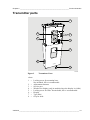
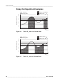
1
USER'S GUIDE
Vaisala HUMICAP® Humidity and
Temperature Transmitter
HMW90 Series
M211399EN-B
PUBLISHED BY
Vaisala Oyj
P.O. Box 26
FI-00421 Helsinki
Finland
Phone (int.): +358 9 8949 1
Fax:
+358 9 8949 2227
Visit our Internet pages at www.vaisala.com.
© Vaisala 2012
No part of this manual may be reproduced in any form or by any means, electronic or
mechanical (including photocopying), nor may its contents be communicated to a third
party without prior written permission of the copyright holder.
The contents are subject to change without prior notice.
Please observe that this manual does not create any legally binding obligations for
Vaisala towards the customer or end user. All legally binding commitments and
agreements are included exclusively in the applicable supply contract or Conditions of
Sale.
________________________________________________________________________________
Table of Contents
CHAPTER 1
GENERAL INFORMATION............................................................................ 5
About This Manual ................................................................... 5
Contents of This Manual ....................................................... 5
Version Information ............................................................... 6
Related Manuals ................................................................... 6
Documentation Conventions ................................................. 6
Safety......................................................................................... 7
ESD Protection...................................................................... 7
Recycling .................................................................................. 7
Regulatory Compliances ......................................................... 8
Patent Notice ............................................................................ 8
Trademarks ............................................................................... 8
License Agreement .................................................................. 8
Warranty.................................................................................... 9
CHAPTER 2
PRODUCT OVERVIEW................................................................................ 11
Introduction to HMW90 Series .............................................. 11
HMW90 Series Transmitters.................................................. 12
Supported Quantities............................................................. 12
Transmitter parts.................................................................... 13
CHAPTER 3
INSTALLATION............................................................................................ 17
Configuration Before Installation ......................................... 17
Configuration Using DIP Switches ...................................... 18
Relay Configuration in DIP Mode........................................ 19
Selecting Location ................................................................. 21
Wiring ...................................................................................... 22
Wiring HMW92 .................................................................... 22
Wiring HMW93 .................................................................... 23
CHAPTER 4
OPERATION................................................................................................. 25
Display..................................................................................... 25
Startup Screens .................................................................. 25
Measurement Screen.......................................................... 26
Indicators on the Display..................................................... 26
Service Port ............................................................................ 27
Connecting With an MI70 Indicator..................................... 27
Connecting With a PC......................................................... 27
Installing the Driver for the USB Service Cable ............. 28
VAISALA ________________________________________________________________________ 1
USER'S GUIDE____________________________________________________________________
Terminal Application Settings.........................................29
List of Serial Commands .......................................................31
Transmitter Information .........................................................32
Show Transmitter Information .............................................32
Show Transmitter Firmware Version ...................................32
Show Transmitter Serial Number ........................................32
Show Transmitter Status .....................................................33
Show Measured Quantities .................................................34
Show Command List ...........................................................34
Show Command Help .........................................................35
Measurement Settings ...........................................................35
Set Environmental Parameters ...........................................35
Select Units .........................................................................36
Analog Output Settings .........................................................36
Set Analog Output Mode .....................................................36
Set Analog Output Scaling ..................................................37
Set Output Clipping and Error Limit.....................................38
Display Settings......................................................................39
Select Quantities to Display ................................................39
Serial Line Output Commands ..............................................40
Start Measurement Output ..................................................40
Stop Measurement Output ..................................................40
Output a Reading Once.......................................................40
Set Output Interval...............................................................41
Set Output Format ...............................................................42
Serial Line Settings ................................................................43
Set Remote Echo ................................................................43
Set Serial Line Response Time...........................................44
Relay Configuration in Custom Mode ..................................44
Set Relay Mode ...................................................................44
Set Relay Quantity and Limits .............................................45
Relay Configuration Examples ............................................46
Calibration and Adjustment Commands..............................47
Adjust Humidity Measurement ............................................47
Show Current RH Adjustment ........................................47
1-point Adjustment of RH Measurement ........................48
2-point Adjustment of RH Measurement ........................48
Clear User Adjustment of RH Measurement..................49
Adjust Temperature Measurement......................................49
Show Current T Adjustment ...........................................49
1-point Adjustment of T Measurement ...........................49
Clear User Adjustment of T Measurement.....................50
Enter Calibration and Adjustment Information ....................50
Testing Commands ................................................................51
Test Analog Outputs............................................................51
Test Relay Operation...........................................................52
Other Commands ...................................................................52
Enable Advanced Serial Commands...................................52
Revert to Factory Settings...................................................53
Reset Transmitter ................................................................53
2 ___________________________________________________________________ M211399EN-B
________________________________________________________________________________
CHAPTER 5
MAINTENANCE ........................................................................................... 55
Periodic Maintenance ............................................................ 55
Cleaning .............................................................................. 55
Calibration and Adjustment ................................................. 56
Adjustment Using Display and Trimmers....................... 57
Adjustment Using an HM70 ........................................... 58
Adjustment Using a PC.................................................. 59
Repair Maintenance ............................................................... 60
Replacing the HTM10 Module............................................. 60
CHAPTER 6
TROUBLESHOOTING ................................................................................. 63
Problem Situations................................................................. 63
Error Messages ...................................................................... 64
Error Messages on the Display ........................................... 64
Error Messages on the Serial Line...................................... 64
View Currently Active Errors .......................................... 64
View Error Table ............................................................ 65
Error State............................................................................... 66
Technical Support .................................................................. 66
Product Returns ..................................................................... 66
CHAPTER 7
TECHNICAL DATA ...................................................................................... 67
Specifications ......................................................................... 67
Spare Parts and Accessories................................................ 68
Dimensions in mm ................................................................. 69
VAISALA ________________________________________________________________________ 3
USER'S GUIDE____________________________________________________________________
List of Figures
Figure 1
Figure 2
Figure 3
Figure 4
Figure 5
Figure 6
Figure 7
Figure 8
Figure 9
Figure 10
Figure 11
Figure 12
Figure 13
Figure 14
Figure 15
Figure 16
Figure 17
Figure 18
Figure 19
Figure 20
Figure 21
Figure 22
Figure 23
Figure 24
HMW90 Series Transmitters ....................................................11
Transmitter Parts ......................................................................13
Opening the Transmitter...........................................................14
Transmitter Parts – Inside ........................................................15
DIP Switch Settings for HMW92 and HMW93..........................18
Relay High in DIP Mode ...........................................................20
Relay Low in DIP Mode ............................................................20
Selecting Transmitter Location .................................................21
Wiring HMW92..........................................................................22
Three-Wire Wiring for HMW92 .................................................22
Wiring HMW93..........................................................................23
Three-Wire Wiring for HMW93 .................................................23
Connecting a Common AC Power Supply ...............................23
HMW93 Startup Screens..........................................................25
Measurement Screen – Normal Operation...............................26
Measurement Screen – Problem With Measurement ..............26
PuTTY Terminal Application.....................................................30
Relay Hi_Active in Custom Mode .............................................46
Relay Lo_active in Custom Mode.............................................46
Trimmer Centering Screen .......................................................57
Trimmer Centering Screen .......................................................57
Replacing the HTM10 Module ..................................................60
HMW90 Series Dimensions......................................................69
Dimensions of the Mounting Base............................................69
List of Tables
Table 1
Table 2
Table 3
Table 4
Table 5
Table 6
Table 7
Table 8
Table 9
Table 10
Table 11
Table 12
Table 13
Table 14
Table 15
Table 16
Table 17
Table 18
Manual Revisions .......................................................................6
Related Manuals.........................................................................6
HMW90 Series Transmitters ....................................................12
Quantities Supported by HMW90 Series..................................12
Rotary Switch and Relay Setpoint ............................................19
Serial Interface Settings ...........................................................29
Basic Serial Commands ...........................................................31
Advanced Serial Commands ....................................................31
FORM Command Parameters..................................................43
FORM Command Modifiers......................................................43
Troubleshooting Table..............................................................63
Error Messages on the Display ................................................64
Error Messages on the Serial Line ...........................................65
Performance .............................................................................67
Operating Environment.............................................................67
Inputs and Outputs ...................................................................68
Mechanics.................................................................................68
HMW90 Series Spare Parts and Accessories..........................68
4 ___________________________________________________________________ M211399EN-B
Chapter 1 ________________________________________________________ General Information
CHAPTER 1
GENERAL INFORMATION
This chapter provides general notes for the manual and HMW90 series
transmitters.
About This Manual
This manual provides information for installing, operating, and
maintaining HMW90 series transmitters. All transmitter models in the
HMW90 series are covered, which means that some information in the
manual is model-specific.
Contents of This Manual
This manual consists of the following chapters:
- Chapter 1, General Information, provides general notes for the manual
and HMW90 series transmitters.
- Chapter 2, Product Overview, introduces the features, advantages, and
the product nomenclature.
- Chapter 3, Installation, provides you with information that is intended
to help you install the HMW90 series transmitters.
- Chapter 4, Operation, contains information that is needed to operate
the HMW90 series transmitters.
- Chapter 5, Maintenance, provides information that is needed in basic
maintenance of the HMW90 series.
- Chapter 6, Troubleshooting, describes common problems, their
probable causes and remedies, and provides contact information for
technical support.
- Chapter 7, Technical Data, provides the technical data of the HMW90
series transmitters.
VAISALA ________________________________________________________________________ 5
USER'S GUIDE____________________________________________________________________
Version Information
Table 1
Manual Code
M211399EN-B
M211399EN-A
Manual Revisions
Description
January 2012. This manual. Updated technical
specification, HMW92 wiring instructions, and
serial command descriptions.
December 2011. First version.
Related Manuals
Table 2
Manual Code
M211398EN
Related Manuals
Manual Name
HMW92 and HMW93 Quick Guide
Documentation Conventions
Throughout the manual, important safety considerations are highlighted
as follows:
WARNING
Warning alerts you to a serious hazard. If you do not read and follow
instructions very carefully at this point, there is a risk of injury or even
death.
CAUTION
Caution warns you of a potential hazard. If you do not read and follow
instructions carefully at this point, the product could be damaged or
important data could be lost.
NOTE
Note highlights important information on using the product.
6 ___________________________________________________________________ M211399EN-B
Chapter 1 ________________________________________________________ General Information
Safety
The HMW90 series transmitter delivered to you has been tested and
approved as shipped from the factory. Note the following precautions:
CAUTION
Do not modify the unit. Improper modification can damage the product
or lead to malfunction.
ESD Protection
Electrostatic Discharge (ESD) can cause immediate or latent damage to
electronic circuits. Vaisala products are adequately protected against
ESD for their intended use. It is possible to damage the product,
however, by delivering electrostatic discharges when touching,
removing, or inserting any objects inside the equipment housing.
To make sure you are not delivering high static voltages yourself:
- Handle ESD sensitive components on a properly grounded and
protected ESD workbench.
- Always hold component boards by the edges and avoid touching the
component contacts.
Recycling
Recycle all applicable material.
Dispose of the unit according to statutory regulations. Do not dispose of
with regular household refuse.
VAISALA ________________________________________________________________________ 7
USER'S GUIDE____________________________________________________________________
Regulatory Compliances
The HMW90 series complies with the following performance and
environmental test standards:
- EMC-Directive
Conformity is shown by compliance with the following standards:
- EN 61326-1: Electrical equipment for measurement, control, and
laboratory use – EMC requirements – for use in industrial locations.
- EN 550022: Information technology equipment – Radio disturbance
characteristics – Limits and methods of measurement.
Patent Notice
The HMW90 series is protected by, for example, the following patents
and their corresponding national rights:
Finnish patent 98861, French patent 6650303, German patent 69418174,
Japanese patent 3585973, UK patent 0665303, U.S. patent 5607564.
Trademarks
HUMICAP® is a registered trademark of Vaisala Oyj.
Windows® is a registered trademark of Microsoft Corporation in the
United States and/or other countries.
License Agreement
All rights to any software are held by Vaisala or third parties. The
customer is allowed to use the software only to the extent that is provided
by the applicable supply contract or Software License Agreement.
8 ___________________________________________________________________ M211399EN-B
Chapter 1 ________________________________________________________ General Information
Warranty
Visit our Internet pages for standard warranty terms and conditions:
www.vaisala.com/warranty.
Please observe that any such warranty may not be valid in case of
damage due to normal wear and tear, exceptional operating conditions,
negligent handling or installation, or unauthorized modifications. Please
see the applicable supply contract or Conditions of Sale for details of the
warranty for each product.
VAISALA ________________________________________________________________________ 9
USER'S GUIDE____________________________________________________________________
This page intentionally left blank.
10 __________________________________________________________________ M211399EN-B
Chapter 2 __________________________________________________________ Product Overview
CHAPTER 2
PRODUCT OVERVIEW
This chapter introduces the features, advantages, and the product
nomenclature.
Introduction to HMW90 Series
The HMW90 series transmitters are wall-mount transmitters for building
automation applications. Transmitter models in the series share the
following common features:
-
Detachable mounting base for easy installation and wiring.
Display (visible or hidden behind the cover).
Sliding cover for accessing maintenance functions.
Adjustment trimmers.
DIP switches for most common configuration tasks.
RS-485 line for temporary service use with hand-held MI70 indicator
or PC.
1111-062
Figure 1
HMW90 Series Transmitters
VAISALA _______________________________________________________________________ 11
USER'S GUIDE____________________________________________________________________
HMW90 Series Transmitters
Table 3 below lists the most important differences between the HMW90
series transmitter models. For technical specifications, see Chapter 7,
Technical Data, on page 67.
Table 3
HMW90 Series Transmitters
Product Code
HMW92
Short Description
Humidity and temperature transmitter with
- two current outputs (4 ... 20 mA)
- display hidden under sliding cover
Humidity and temperature transmitter with
- two current outputs (4 ... 20 mA)
- visible display
Humidity and temperature transmitter with
- two voltage outputs (0 ... 5 V or 0 ... 10 V)
- relay
- display hidden under sliding cover
Humidity and temperature transmitter with
- two voltage outputs (0 ... 5 V or 0 ... 10 V)
- relay
- visible display
HMW92D
HMW93
HMW93D
Supported Quantities
Table 4
Quantities Supported by HMW90 Series
Quantity
Symbol
Temperature T
Unit(s)
°C
°F
%
Relative
humidity
RH
Dewpoint
Td
°C
°F
Dewpoint
Tdf
°C
°F
Dewpoint
depression
Wet bulb
temperature
dTd
°C
°F
°C
°F
Absolute
humidity
Mixing ratio
a
x
Enthalpy
h
Tw
g/m3
gr/ft3
g/kg
gr/lb
kJ/kg
btu/lb
Description
Temperature in Celsius or
Fahrenheit scale.
Ratio of the partial pressure of
water vapor in the air to the
saturation vapor pressure of air
at the current temperature.
Temperature at which the water
vapor in the air will condense into
water at the current pressure.
Same as Td, except when the
dewpoint is below 0 °C, the
transmitter outputs frostpoint (Tf)
instead of dewpoint.
Difference between ambient
temperature and dewpoint (Tdf).
The minimum temperature that
can be reached by evaporative
cooling in the current conditions.
Quantity of water in a cubic meter
(or cubic foot) of air.
Ratio of water vapor mass per
kilogram (or pound) of dry air.
Sum of the internal energy of a
thermodynamic system.
12 __________________________________________________________________ M211399EN-B
Chapter 2 __________________________________________________________ Product Overview
Transmitter parts
1
6
2
7
3
4
8
5
1201-004
Figure 2
Transmitter Parts
where
1 = Locking screw for mounting base.
Not included, M3×6 recommended.
2 = Adjustment trimmers
3 = Service port
4 = Window for display (only in models where the display is visible)
5 = Locking screw for slide. Not included, M3×6 recommended.
6 = Display
7 = Type label
8 = Grip for slide
VAISALA _______________________________________________________________________ 13
USER'S GUIDE____________________________________________________________________
1
1201-005
Figure 3
Opening the Transmitter
where
1 = Push tab down with a screwdriver to open the transmitter.
14 __________________________________________________________________ M211399EN-B
Chapter 2 __________________________________________________________ Product Overview
1
7
2
5
3
6
4
N
8
on
-M
e tr
Td
ic
0 ..
.5
V
R
e la
y
R
O
n
e la
y
H
ig
h
C
us
to
m
R e la y S
e t P o in t
M
e tr
ic
R
H
0V
ff
.1 y O L
0 .. e la
y
R
e la
R
ow
D
IP
10
9
1201-006
Figure 4
Transmitter Parts – Inside
where
1
2
3
4
5
=
=
=
=
=
6 =
7 =
8 =
9 =
10 =
Mounting base
Opening for cable (wiring from top)
Terminal label
Opening for cable (wiring from behind)
Orientation arrow – should point up after the mounting base has
been installed.
Place for zip tie (for cable strain relief)
Transmitter body
DIP switches for common configuration options; see section
Configuration Using DIP Switches on page 18.
HTM10 module with HUMICAP 180R sensor.
Rotary switch for relay setpoint (only for models with relay); see
section Relay Configuration in DIP Mode on page 19.
VAISALA _______________________________________________________________________ 15
USER'S GUIDE____________________________________________________________________
This page intentionally left blank.
16 __________________________________________________________________ M211399EN-B
Chapter 3 _______________________________________________________________ Installation
CHAPTER 3
INSTALLATION
This chapter provides you with information that is intended to help you
install the HMW90 series transmitters.
Configuration Before Installation
If you need to change the settings of the transmitter, it is best to do this
before it has been installed. You can configure HMW90 series
transmitters in two ways:
- Using the DIP switches (and rotary switch on the HMW93) on the
component board. See the following sections for instuctions:
- Configuration Using DIP Switches on page 18
- Relay Configuration in DIP Mode on page 19
- Configuring the settings in software through the service port. See
connection instructions and serial line commands in Chapter 4,
Operation, on page 25.
These two configuration methods are mutually exclusive. If the DIP
switch configuration is used, software settings have no effect on settings
that are controlled by the DIP switches. DIP switch number 8 is the
master switch that controls which configuration method is used.
VAISALA _______________________________________________________________________ 17
USER'S GUIDE____________________________________________________________________
Configuration Using DIP Switches
ric
et
M
nNo Td
om
st
u
C
1 2 3 4 5 6 7 8
ric RH
et
M
P
DI
HMW92
ric
n gh
et
O Hi
M
V y y
n..5 la la
No Td 0. Re Re
om
st
u
C
1 2 3 4 5 6 7 8
f
ric RH 0V Of ow
1
L
et
.
y
.
M
0. ela lay
R Re
P
DI
HMW93
1111-066
Figure 5
DIP
1
2
DIP Switch Settings for HMW92 and HMW93
Position
Non-metric
Metric
Td
RH
3
4
5
6
7
8
NOTE
0...5V
0...10V
Relay On
Relay Off
Relay High
Relay Low
Not used
Not used
Custom
DIP
Setting
Non-metric units (°F)
Metric units (°C)
Td (dewpoint) as humidity quantity on display and
analog output
RH (relative humidity) as humidity quantity on display
and analog output
0...5V analog output (both channels)
0...10V analog output (both channels)
Relay enabled
Relay disabled
Relay closed when RH above setpoint
Relay closed when RH below setpoint
Configuration through service port only
Configuration by DIP switches only
If DIP switch 8 is set to Custom, the transmitter ignores all other DIP
switch settings. In custom mode the transmitter uses settings that are
configured in software using the service port.
If you change the position of DIP switch 8, note the following:
- When changing from Custom to DIP: Current custom settings are
overwritten by the settings from the DIP switches at next power up.
Settings that do not have DIP switches remain unchanged, except for
display layout (DSEL command) that is set to default.
- When changing from DIP to Custom: The DIP settings that were
used when the power was last on are carried over to the custom
settings at next power up.
18 __________________________________________________________________ M211399EN-B
Chapter 3 _______________________________________________________________ Installation
Relay Configuration in DIP Mode
NOTE
Relay is included on HMW93 transmitters only.
When the transmitter is configured using DIP switches, the functioning
of the relay is configured by DIP switch 5 and the rotary switch on the
component board:
- DIP 5 determines if the relay is closed above or below the setpoint.
- The position of the rotary switch determines the setpoint according to
the table below.
Table 5
Rotary Switch and Relay Setpoint
Rotary Switch Position
0
1
2
3
4
5
6
7
8
9
NOTE
Relay Setpoint
5 %RH
10 %RH
20 %RH
30 %RH
40 %RH
50 %RH
60 %RH
70 %RH
80 %RH
90 %RH
The rotary switch only has 10 positions. Do not turn the switch so that it
is between two positions.
For examples of relay behavior in DIP mode, see Figure 6 and Figure 7
on page 20. Note also the following:
- Relay operation in DIP mode is always linked to RH measurement.
- Relay contacts are open if the transmitter is in error state (an active
error is present).
- Relay contacts are open when transmitter is powered off.
If you need to configure the relay for some other quantity or need
additional configuration options, see section Relay Configuration in
Custom Mode on page 44.
VAISALA _______________________________________________________________________ 19
USER'S GUIDE____________________________________________________________________
Rotary switch set to 6 (60 %RH)
DIP 5 set to “Relay High”
Relay closed
Relay open
100
Relative Humidity (%)
90
80
70
60
50
40
30
20
10
0
Time
1111-117
Figure 6
Relay High in DIP Mode
Rotary switch set to 6 (60 %RH)
DIP 5 set to “Relay Low”
Relay closed
Relay open
100
Relative Humidity (%)
90
80
70
60
50
40
30
20
10
0
Time
1111-118
Figure 7
NOTE
Relay Low in DIP Mode
There is a hysteresis around the setpoint value (2 %RH in both
directions) to prevent rapid relay switching when the measured value
moves around the setpoint. This means that the relay will not close or
open exactly at the setpoint, but slightly above and below.
20 __________________________________________________________________ M211399EN-B
Chapter 3 _______________________________________________________________ Installation
Selecting Location
The conditions at the location should represent well the area of interest.
Do not install the transmitter on the ceiling. Avoid placing the transmitter
near heat and moisture sources, close to the discharge of the supply air
ducts, and in direct sunlight.
1111-070
Figure 8
Selecting Transmitter Location
Use the mounting holes to attach the mounting base securely. Use at least
two screws (not included, M3x6 recommended). Remember to leave
sufficient clearance below the transmitter to operate the slide. For
mounting dimensions, see section Dimensions in mm on page 69.
CAUTION
The arrow on the mounting base must point straight up after installation.
Proper orientation is important: air must flow through the vents on the
bottom and top.
VAISALA _______________________________________________________________________ 21
USER'S GUIDE____________________________________________________________________
Wiring
Connect the wiring to the screw terminals on the mounting base. The
supply voltage and terminal assignments are model-specific. Max wire
size 2 mm2 (AWG14).
After completing the wiring, connect the transmitter body over the
mounting base. Note that mounting bases are model-specific.
Wiring HMW92
You must connect the RH channel of the HMW92, even if you only want
to measure temperature. Connecting the T channel is optional.
-T +T -RH +RH
mA
Power supply
10 ... 28 VDC
RL = 0 ... 600 Ω
Power supply
10 ... 28 VDC
RL = 0 ... 600 Ω
mA
1111-067
Figure 9
Wiring HMW92
If you want to use a single power supply for the HMW92, you must
connect the positive terminals (+T and +RH) together.
-T +T -RH +RH
mA
mA
Power supply
10 ... 28 VDC
RL = 0 ... 600 Ω
1211-007
Figure 10
Three-Wire Wiring for HMW92
22 __________________________________________________________________ M211399EN-B
Chapter 3 _______________________________________________________________ Installation
Wiring HMW93
Recommended wiring for long cables:
Relay -RH +RH -T +T -Vs +Vs
Power supply
18 ... 35 VDC
or 24 VAC ±20%
RL = 10 kΩ min.
V
V
max. 50 VDC
500 mA
1111-068
Figure 11
Wiring HMW93
3-wire connection with -Vs as common ground. Maximum cable
resistance is 2.5 Ω (24V supply, 0 ... 10 V output, relay not used).
Relay -RH +RH -T +T -Vs +Vs
Power supply
18 ... 35 VDC
or 24 VAC ±20%
RL = 10 kΩ min.
V
V
1111-069
Figure 12
Three-Wire Wiring for HMW93
If you are connecting a common 24 VAC power supply to several
transmitters, make sure to connect the same terminal to +Vs and –Vs on
all transmitters. This will avoid a short-circuit through the shared
common line at the controller; see Figure 13 below.
HMW93
24 VAC
Supply
voltage
+Vs
OUT
-Vs
GND
CONTROLLER
Signal
output
Shared
common
line
HMW93
Supply
voltage
+Vs
OUT
-Vs
GND
Signal
output
1112-026
Figure 13
Connecting a Common AC Power Supply
VAISALA _______________________________________________________________________ 23
USER'S GUIDE____________________________________________________________________
This page intentionally left blank.
24 __________________________________________________________________ M211399EN-B
Chapter 4 ________________________________________________________________ Operation
CHAPTER 4
OPERATION
This chapter contains information that is needed to operate the HMW90
series transmitters.
Display
Startup Screens
When the transmitter is powered on, it displays a sequence of
information screens. The screens are shown for a few seconds each.
1111-073, 1111-074
Figure 14
HMW93 Startup Screens
VAISALA _______________________________________________________________________ 25
USER'S GUIDE____________________________________________________________________
Measurement Screen
Measurement screen shows the measured quantities and currently active
indicators.
1111-071
Figure 15
Measurement Screen – Normal Operation
If there is a problem with measurement, affected readings are replaced
with stars. The alarm indicator and an error message will also appear on
the screen.
1111-072
Figure 16
Measurement Screen – Problem With Measurement
Indicators on the Display
Indicator
Position on Screen
Top right
Top right
Top left
Bottom left
Meaning
Is shown when relay contacts are open
(HMW93 only).
Is shown when relay contacts are closed
(HMW93 only).
Is shown when an MI70 Indicator is
connected to the service port.
Is shown if an error is active. The error
message is written after the indicator. See
section Error Messages on the Display on
page 64.
26 __________________________________________________________________ M211399EN-B
Chapter 4 ________________________________________________________________ Operation
Service Port
You can connect to the service port on the HMW90 series transmitters
using a PC or an MI70 indicator. The MI70 indicator is the hand-held
display device that is included with, for example, the Vaisala
HUMICAP® Hand-Held Humidity and Temperature Meter HM70.
CAUTION
The service port is not galvanically isolated from the rest of the
transmitter electronics. Connect only equipment with a floating power
supply (not grounded) to the service port. If you connect a device that is
grounded to a different potential than the transmitter’s power supply, you
will affect the accuracy of the transmitter’s analog outputs. You may
even affect the transmitter’s functionality or cause damage to the
transmitter.
Connecting With an MI70 Indicator
When connecting using an MI70 indicator, use the connection cable for
HM70 hand-held meter (Vaisala order code 219980). The following
functionality is available when using the MI70:
- Standard MI70 functions such as viewing, logging, and graphs of
measurement results.
- Calibration and adjustment fuctions for the transmitter. For more
information, see section Adjustment Using an HM70 on page 58.
- Setting of the pressure compensation value for humidity measurement
(Environment menu in the MI70).
Connecting With a PC
Connecting with a PC allows you to configure and troubleshoot your
transmitter using serial line commands. For a list of commands, see
section List of Serial Commands on page 31.
When connecting using a PC, use the Vaisala USB cable (Vaisala order
code 219690) and a suitable terminal application:
- If you have not used the Vaisala USB cable before, install the driver
that came with the cable. Refer to section Installing the Driver for the
USB Service Cable on page 28 for detailed instructions.
- For more information on using a terminal application, see section
Terminal Application Settings on page 29.
VAISALA _______________________________________________________________________ 27
USER'S GUIDE____________________________________________________________________
Installing the Driver for the USB Service Cable
Before taking the USB service cable into use, you must install the
provided USB driver on your PC. When installing the driver, you must
acknowledge any security prompts that may appear. The driver is
compatible with Windows 2000, Windows XP, Windows Server 2003,
and Windows Vista.
1.
Check that the USB service cable is not connected. Disconnect the
cable if you have already connected it.
2.
Insert the media that came with the cable, or download the driver
from www.vaisala.com.
3.
Execute the USB driver installation program (setup.exe), and
accept the installation defaults. The installation of the driver may
take several minutes.
4.
After the driver has been installed, connect the USB service cable
to a USB port on your PC. Windows will detect the new device,
and use the driver automatically.
5.
The installation has reserved a COM port for the cable. Verify the
port number, and the status of the cable, using the Vaisala USB
Instrument Finder program that has been installed in the
Windows Start menu.
Windows will recognize each individual cable as a different device, and
reserve a new COM port. Remember to use the correct port in the
settings of your terminal program.
There is no reason to uninstall the driver for normal use. However, if you
wish to remove the driver files and all Vaisala USB cable devices, you
can do so by uninstalling the entry for Vaisala USB Instrument Driver
from the Add or Remove Programs (Programs and Features in
Windows Vista) in the Windows Control Panel.
28 __________________________________________________________________ M211399EN-B
Chapter 4 ________________________________________________________________ Operation
Terminal Application Settings
The serial interface settings of the service port are presented in Table 6
below. The settings are fixed, and cannot be changed by the user.
Table 6
Property
Baud rate
Parity
Data bits
Stop bits
Flow control
Serial Interface Settings
Description / Value
19200
None
8
1
None
The steps below describe how to connect to the transmitter using the
PuTTY terminal application for Windows (available for download at
www.vaisala.com) and a USB serial interface cable:
1.
2.
3.
4.
5.
6.
Connect the USB serial interface cable between your PC and the
service port of the transmitter.
Start the PuTTY application.
Select the Serial settings category, and check that the correct COM
port is selected in the Serial line to connect to field.
Note: You can check which port the USB cable is using with the
Vaisala USB Instrument Finder program that has been installed
in the Windows Start menu.
Check that the other serial settings are correct for your connection,
and change if necessary. Flow control should be set to None unless
you have a reason to change it.
Click the Open button to open the connection window and start
using the serial line.
Note: If PuTTY is unable to open the serial port you selected, it
will show you an error message instead. If this happens, restart
PuTTY and check the settings.
You may need to adjust the Local echo setting in the Terminal
category to see what you are typing on the serial line. To access the
configuration screen while a session is running, click the right
mouse button over the session window, and select Change
Settings... from the pop-up menu.
VAISALA _______________________________________________________________________ 29
USER'S GUIDE____________________________________________________________________
0807-004
Figure 17
PuTTY Terminal Application
30 __________________________________________________________________ M211399EN-B
Chapter 4 ________________________________________________________________ Operation
List of Serial Commands
All commands can be issued either in uppercase or lowercase. In the
command examples, the keyboard input by the user is in bold type.
The notation <cr> refers to pressing the carriage return (Enter) key on
your computer keyboard. Enter a <cr> to clear the command buffer
before starting to enter commands.
Table 7
Basic Serial Commands
Command
?
CALCS
ECHO
ENV
ERRT
ERRS
FORM [modifier string]
HELP
INTV [0 ... 9999 s/min/h]
PASS [9000]
R
RESET
S
SDELAY [0 ... 255]
SEND
SNUM
STATUS
UNIT [m/n]
VERS
Table 8
Description
Show transmitter information.
Show all measured quantities.
Show or set remote echo mode.
Show or set environmental parameters.
Show error table.
Show currently active errors.
Show or set output format.
Show list of currently available serial commands.
Set continuous output interval for R command.
Access advanced serial commands.
Start the continuous outputting.
Reset the transmitter.
Stop the continuous outputting.
Show or set serial line transmission delay in
milliseconds.
Output measurement message once.
Show transmitter serial number.
Show transmitter status.
Select metric or non-metric units.
Show transmitter firmware version.
Advanced Serial Commands
Command
AMODE
AOVER
ASEL
ATEST
CDATE
CRH
CT
CTEXT
DSEL
FRESTORE
RMODE
RSEL
RTEST [open/closed]
Description
Show or set analog output mode.
Show or set overrange and clipping behavior.
Show or set analog output quantity.
Test analog putput.
Show or set calibration date.
Calibrate and adjust RH measurement.
Calibrate and adjust T measurement.
Show or set calibration information.
Select quantities to display on screen.
Restore transmitter to factory settings.
Show or set relay operation mode.
Show or set relay quantity and limits.
Test relay operation.
VAISALA _______________________________________________________________________ 31
USER'S GUIDE____________________________________________________________________
Transmitter Information
Show Transmitter Information
The ? command outputs a listing of device information.
?<cr>
Example:
>?
Device
SW version
SNUM
: HMW93
: 1.00.0.0000
: G5130008
HTM10 module information
Software version
: 1.00.0
SNUM
: G5130007
Show Transmitter Firmware Version
Use the VERS command to show the transmitter model and firmware
version.
VERS<cr>
Example:
>vers
HMW93 / 1.00.0
Show Transmitter Serial Number
Use the SNUM command to show the transmitter serial number.
SNUM<cr>
Example:
>snum
Serial number
: G5130008
32 __________________________________________________________________ M211399EN-B
Chapter 4 ________________________________________________________________ Operation
Show Transmitter Status
Use the STATUS command to view detailed information on transmitter
model and configuration.
STATUS<cr>
Example:
>status
Device Name
Copyright
SW Name
SW Model
SW version
Serial number
Address
:
:
:
:
:
:
:
HMW93
Copyright Vaisala Oyj 2011
XM90
XM9x
1.00.0.0000
G5130008
0
SUB FUNCTIONS
* Serial Port (COM1) *
Mode
: STOP
* Error Manager (ERR) *
Status
: NORMAL
Active errors
: 0
* MCI communication (MCI) *
Status
: NORMAL
* Analog output 1 (AOUT1) *
Quantity
: T
Input range
: -5.000 ... 55.000 'C
Output range
: 0.000 ... 5.000 V
Output clipping
: 0.00 % (0.00 ... 5.00 V)
Valid output range : 5.00 % (-0.25 ... 5.25 V)
Error value
: 5.500 V
Input now
: 24.937 'C
Output now
: 2.495 V
State
: Normal
* Analog output 2 (AOUT2) *
Quantity
: RH
Input range
: 0.000 ... 100.000 %
Output range
: 0.000 ... 5.000 V
Output clipping
: 0.00 % (0.00 ... 5.00 V)
Valid output range : 5.00 % (-0.25 ... 5.25 V)
Error value
: 5.500 V
Input now
: 2.365 %
Output now
: 0.118 V
State
: Normal
* Relay output (RELAY) *
Quantity
: RH
Setpoint
: 88.000 ... 92.000 %
Mode
: Lo_Active
Status
: Closed
* Measurement module (HTM10) *
Status
: NORMAL
Factory date
: 2011-11-09
VAISALA _______________________________________________________________________ 33
USER'S GUIDE____________________________________________________________________
Show Measured Quantities
Use the CALCS command to list the measurement quantities that the
transmitter supports. RH and T are measured directly by the transmitter,
the rest are calculated based on the measured values.
CALCS<cr>
Example:
>calcs
RH
T
Tdf
Td
Tw
h
x
a
dTd
-
Relative Humidity
Temperature
Dew/Frost point temperature
Dew point temperature
Wetbulb temperature
Enthalpy
Mixing ratio
Absolute humidity
Dew/frostpoint depression
Show Command List
Use the HELP command to list the currently available serial commands.
If the PASS command has not been used, only the basic serial commands
are available.
HELP<cr>
Example (shows basic serial commands, advanced commands are not
enabled here):
>help
?
CALCS
ECHO
ENV
ERRT
ERRS
FORM
HELP
INTV
PASS
R
RESET
SDELAY
SEND
SNUM
STATUS
UNIT
VERS
34 __________________________________________________________________ M211399EN-B
Chapter 4 ________________________________________________________________ Operation
Show Command Help
To see a short description of an individual command, issue the command
with a question mark as a parameter.
Example:
>calcs ?
Display measured quantities
Measurement Settings
Set Environmental Parameters
Use the ENV command to set environmental parameters that affect the
measurement. For HMW90 series transmitters you can set the ambient
pressure value that is used for pressure compensation of calculated
quantities.
ENV [pressure]<cr>
where
pressure = Ambient pressure in hPa.
Example:
>env 1013.3
Pressure (hPa)
: 1013.3
VAISALA _______________________________________________________________________ 35
USER'S GUIDE____________________________________________________________________
Select Units
Use the UNIT command to select metric or non-metric output units.
UNIT [x]<cr>
where
x
=
Selects the unit type to output:
m = metric units, for example, Celsius
n = non-metric units, for example, Fahrenheit
Example:
>unit m
Unit
: Metric
Analog Output Settings
Set Analog Output Mode
Use the AMODE command to set the analog output mode and error
level. Note that you cannot change between analog output types, for
example, from voltage to current output.
AMODE [channel lo_value hi_value error_value]<cr>
where
channel
=
lo_value =
hi_value =
error_value =
Analog output channel, 1 or 2.
Low limit of the channel.
High limit of the channel.
Error value of the channel.
Example (show current configuration):
>pass 9000
>amode
Aout 1 range ( V)
Aout 2 range ( V)
: 0.00 ... 5.00 (error: 5.50)
: 0.00 ... 5.00 (error: 5.50)
Example (set channel 1 to 0 ... 1 V output, with error level at 2 V):
>amode 1 0 1 2
Aout 1 range ( V)
: 0.00 ... 1.00 (error: 2.00)
36 __________________________________________________________________ M211399EN-B
Chapter 4 ________________________________________________________________ Operation
Set Analog Output Scaling
Use the ASEL command to select the output quantity and scaling for
analog output channels.
ASEL [channel quantity lo_value hi_value]<cr>
where
channel = Analog output channel, 1 or 2.
quantity = Quantity that is output on the channel.
Available quantities are:
RH
relative humidity
T
temperature
Tdf
dew/frost point temperature
Td
dew point temperature
Tw
wetbulb temperature
h
enthalpy
x
mixing ratio
a
absolute humidity
dTd
dew/frost point depression
lo_value = Low limit of the scaling, in the units of the selected
quantity.
hi_value = High limit of the scaling in the units of the selected
quantity.
Example (set channel 1 to output dewpoint, in the range -10 ... 20 °C):
>pass 9000
>asel 1 TD -10 20
Aout 1 quantity
: Td (-10.00 ... 20.00 'C)
VAISALA _______________________________________________________________________ 37
USER'S GUIDE____________________________________________________________________
Set Output Clipping and Error Limit
Use the AOVER command to define the behavior of the analog outputs
when the measured value is outside the scaled output range.
AOVER [channel clip% valid%]<cr>
where
channel = Analog output channel, 1 or 2.
clip%
= Output margin (%) at which the output is clipped.
Range 0 ... 20.
valid% = Output margin (%) at which the output of the channel
goes into the error state. Range 0 ... 20. The error state is
defined using the AMODE command, see section Set
Analog Output Mode on page 36.
For example, first check the current settings using the ASEL and
AMODE commands:
>pass 9000
>asel
Aout 1 quantity
Aout 2 quantity
: RH (0.00 ... 100.00 %)
: T (-5.00 ... 55.00 'C)
>amode
Aout 1 range ( V)
Aout 2 range ( V)
: 1.00 ... 5.00 (error: 6.00)
: 1.00 ... 5.00 (error: 6.00)
The quantity for channel 2 is T, with standard output range 1 ... 5 V and
scaling -5 ... 55 °C. Now give the AOVER command:
>aover 2 10.0 20.0
Aout 2 clipping
Aout 2 error limit
: 10.00 %
: 20.00 %
Channel 2 now behaves like this:
- Clipping is now set to 10%, meaning the output is allowed to vary
between 0.6 ... 5.4 V. The channel will output the measurement for
-11 ... 61 °C, but range 1 ... 5 V remains scaled to show -5 ... 55 °C.
- Error limit is 20%, which means channel 2 will show the error state
(6 V) when the measured value is 20% outside the scaled output
range. With the settings above, this will happen if the measured
temperature is outside range -17 ... 67 °C.
- The output will never actually be between 5.4 and 6.0 V because of
clipping.
38 __________________________________________________________________ M211399EN-B
Chapter 4 ________________________________________________________________ Operation
Display Settings
Select Quantities to Display
Use the DSEL command to select the quantities that are displayed on the
transmitter screen. You can select quantities by abbreviation, or select
same quantities as are assigned to the analog outputs. If only one quantity
is selected, it is shown vertically centered on the transmitter screen.
DSEL [Q1 Q2 Q2]<cr>
where
Q1
Q2
Q3
= First quantity to show on the screen. Available quantities are:
out1
Same quantity as analog output channel 1
out2
Same quantity as analog output channel 2
RH
relative humidity
T
temperature
Tdf
dew/frost point temperature
Td
dew point temperature
Tw
wetbulb temperature
h
enthalpy
x
mixing ratio
a
absolute humidity
dTd
dew/frost point depression
= Second quantity to show on the screen. Available quantities
are the same as for Q1.
= Third quantity to show on the screen. Available quantities are
the same as for Q1.
Example (show currently displayed quantities):
>pass
>dsel
Quant
Quant
Quant
9000
1
2
3
: T
: RH
: Disabled
Example (change display to only show RH):
>dsel RH
OK
Example (change display to show same quantities as are assigned to
analog output channels):
>dsel out1 out2
OK
VAISALA _______________________________________________________________________ 39
USER'S GUIDE____________________________________________________________________
Serial Line Output Commands
Start Measurement Output
Use the R command to start the continuous outputting of measurement
values as an ASCII text string to the serial line. The format of the
measurement message is set with the FORM command.
R<cr>
Example (measurement message in default format):
>r
RH =
RH =
RH =
RH =
...
21.71
21.72
21.77
21.77
%RH
%RH
%RH
%RH
T
T
T
T
=
=
=
=
23.13
23.12
23.12
23.12
'C
'C
'C
'C
Outputting the results continues in intervals issued with the command
INTV. You can stop the output with the S command. Since the interface
is half-duplex, you must enter the commands when the transmitter is not
outputting.
Stop Measurement Output
You can stop the measurement output with the S command:
S<cr>
Output a Reading Once
Use the SEND command to output a single measurement message.
SEND<cr>
Example:
>send
RH = 21.72 %RH
T = 23.12 'C
40 __________________________________________________________________ M211399EN-B
Chapter 4 ________________________________________________________________ Operation
Set Output Interval
Use the INTV command to change the output interval of the
automatically repeating measurement messages. The measurement
messages are repeated in the RUN mode, or after the R command has
been given.
INTV [n xxx]<cr>
where
n
xxx
= time interval, range 0 ... 9999.
= time unit = "S", "MIN", or "H"
The shortest output interval (with n = 0) outputs the measurement
messages as quickly as the transmitter produces them, without additional
delay.
Example:
>intv 1 min
Output interval
: 1 min
VAISALA _______________________________________________________________________ 41
USER'S GUIDE____________________________________________________________________
Set Output Format
Use the serial line command FORM to change the measurement message
sent by the transmitter on the service port. You can freely define the
output message to include the desired parameters, formatting options,
text strings, and additional fields.
FORM [modifier string]<cr>
where
modifier string =
String of parameters and modifiers that defines the
output format, length 1 ... 150 characters.
Maximum length may be shorter when text strings
are used. See Table 9 and Table 10 on page 43,
and examples below.
Command to set default format:
>form /
Example of default output:
RH =
RH =
RH =
RH =
...
5.17
5.17
5.18
5.18
%RH
%RH
%RH
%RH
T
T
T
T
=
=
=
=
24.33
24.33
24.33
24.33
'C
'C
'C
'C
Command to set output format as Tdf and T with Modulus-256
checksum:
>form "Tdf =" U3 4.2 tdf "
T =" U3 3.2 t CS2 \r \n
Output example:
Tdf
Tdf
Tdf
Tdf
...
=
=
=
=
-15.72
-15.71
-15.71
-15.69
'C
'C
'C
'C
T
T
T
T
=
=
=
=
24.38
24.38
24.38
24.38
'C
'C
'C
'C
C9
C8
C8
CF
Command to set output format as Tdf and T, with start of text (ASCII
character 002) and end of text (003) ASCII codes, and without line feed
and carriage return at the end:
>form #002 "Tdf =" U3 3.2 tdf "
T =" U3 3.2 t #003
Output example (ASCII codes not visible here):
Tdf =-15.14 'C T = 24.40 'CTdf =-15.14 'C T = 24.40 'CTdf
=-15.14 'C T = 24.40 'CTdf =-15.14 'C T = 24.40 'CTdf =15.13 'C T = 24.40 'CTdf =-15.13 'C T = 24.40 'C ...
42 __________________________________________________________________ M211399EN-B
Chapter 4 ________________________________________________________________ Operation
Table 9
FORM Command Parameters
Measured Parameter
Relative humidity
Temperature
Dew/frost point temperature
Dewpoint temperature
Wetbulb temperature
Enthalpy
Mixing ratio
Absolute humidity
Dew/frost point depression
Table 10
Modifier
x.y
#t
#r
#n
""
#xxx
Ux
CS2
CS4
CSX
NOTE
Abbreviation in FORM Command
RH
T
Tdf
Td
Tw
h
x
a
dTd
FORM Command Modifiers
Description
Length modifier (number of digits and decimal places)
Tabulator
Carriage-return
Line feed
String constant, length 1 ... 15 characters
ASCII code value (decimal) of a special character;
for example, #027 for ESC
Shows the name of the measurement unit using “x” number
of characters. For example, U3 shows the name of the
measurement unit with three characters
Modulus-256 checksum of message sent so far, ASCII
encoded hexadecimal notation
Modulus-65536 checksum of message sent so far, ASCII
encoded hexadecimal notation
NMEA xor-checksum of message sent so far, ASCII encoded
hexadecimal notation
When entering modifiers, you can also use the backslash character “\”
instead of the hash “#”.
Serial Line Settings
Set Remote Echo
Use the ECHO command to enable or disable remote echo by the
transmitter.
ECHO [on/off]<cr>
Example:
>echo on
Echo
: ON
VAISALA _______________________________________________________________________ 43
USER'S GUIDE____________________________________________________________________
Set Serial Line Response Time
With the SDELAY command you can set delay (response time) of the
serial line, or view the currently set delay value.
SDELAY [delay]<cr>
where
delay =
Serial line delay in milliseconds, range 1 … 1000.
Example:
>sdelay 5
COM1 transmit delay : 5
Relay Configuration in Custom Mode
NOTE
Relay is included on HMW93 transmitters only.
Additional configuration options are available when relay functionality is
configured via software. The configuration is done using the RMODE
and RSEL commands. For examples, see section Relay Configuration
Examples on page 46.
Set Relay Mode
Use the RMODE command to show or set the relay activation mode.
RMODE [mode]<cr>
where
mode =
Activation mode of the relay. Options are:
None (relay is disabled, always open)
Lo_active (relay closed when below setpoint)
Hi_active (relay closed when above setpoint)
Fault (relay closed when transmitter in error state)
Not_fault (relay closed when transmitter not in error state)
Example (set relay to Lo_active mode):
>pass 9000
>rmode lo_active
Relay mode
: Lo_Active
44 __________________________________________________________________ M211399EN-B
Chapter 4 ________________________________________________________________ Operation
Set Relay Quantity and Limits
Use the RSEL command to show or set the quantity that controls the
relay, and the limits that are applied.
RSEL [quantity lo_value hi_value]<cr>
where
quantity
= Quantity that controls the relay. Available quantities are:
RH
relative humidity
T
temperature
Tdf
dew/frost point temperature
Td
dew point temperature
Tw
wetbulb temperature
h
enthalpy
x
mixing ratio
a
absolute humidity
dTd
dew/frost point depression
Disabled no quantity, relay disabled
lo_value = Low limit of relay activation.
hi_value = High limit of relay activation.
Example (show current settings):
>pass 9000
>rsel
Relay configuration
: RH (88.00 ... 92.00 %)
Example (set temperature as relay quantity, low limit 25, high limit 30):
>rsel t 25 30
Relay configuration
: T (25.00 ... 30.00 'C)
VAISALA _______________________________________________________________________ 45
USER'S GUIDE____________________________________________________________________
Relay Configuration Examples
RSEL RH 60 70
RMODE Hi_Active
Relay closed
Relay open
100
Relative Humidity (%)
90
80
70
60
50
40
30
20
10
0
Time
1111-119
Figure 18
Relay Hi_Active in Custom Mode
RSEL RH 60 70
RMODE Lo_Active
Relay closed
Relay open
100
Relative Humidity (%)
90
80
70
60
50
40
30
20
10
0
Time
1111-120
Figure 19
Relay Lo_active in Custom Mode
46 __________________________________________________________________ M211399EN-B
Chapter 4 ________________________________________________________________ Operation
Calibration and Adjustment Commands
The following sections describe the calibration and adjustment
commands of the HMW90 series. For general information on performing
calibration and adjustment on the serial line, see section Adjustment
Using a PC on page 59.
The 1-point humidity adjustment of the HMW90 series adjusts both
offset and gain, depending on the adjustment condition. In a dry
condition (for example, 11 %RH), offset is adjusted more than gain.
NOTE
The 1-point humidity adjustment requires that the target condition is at
least 50% of the currently measured value. This prevents the user from
making excessive corrections that are very unlikely to be needed.
However, if you feel that you may have done an incorrect adjustment,
you can easily remove the adjustment using the CRH RESET command.
Adjust Humidity Measurement
Use the CRH command to perform a humidity adjustment of the relative
humidity (RH) measurement. You can do a 1-point or a 2-point
adjustment, or clear the adjustment information from the HTM10
module. Note that the factory adjustment will remain intact when user
adjustment is cleared.
Show Current RH Adjustment
CRH<cr>
Example (showing default offset and gain):
>pass 9000
>crh
RH Gain
RH Offset
: 1.000
: 0.000
VAISALA _______________________________________________________________________ 47
USER'S GUIDE____________________________________________________________________
1-point Adjustment of RH Measurement
The 1-point adjustment adjusts both offset and gain depending on the
adjustment condition. The same type of adjustment is done when turning
the RH trimmer.
Place the transmitter in the reference condition and allow it to stabilize
before entering the adjustment.
CRH [ONE] [x]<cr>
where
x =
The reference humidity condition (%RH) that the transmitter
should be showing.
Example:
>pass 9000
>crh one 11
OK
2-point Adjustment of RH Measurement
CRH [LO | HI] [x]<cr>
where
LO = Adjustment point at the dry end (low RH).
HI = Adjustment point at the wet end (high RH). The difference
between the two points should be at least 30 %RH.
x = The reference humidity condition (%RH) that the transmitter
should be showing.
The 2-point correction is not applied immediately – you must use the
CRH SAVE command to store your adjustment to the HTM10 module.
If you have entered user adjustments using the CRH command but do not
wish to commit them, use the CRH CANCEL command.
CRH [SAVE | CANCEL]<cr>
Example (two point adjustment, low point 11 %RH and high point 75
%RH):
>pass 9000
>crh lo 11
OK
>crh hi 75
OK
>crh save
OK
48 __________________________________________________________________ M211399EN-B
Chapter 4 ________________________________________________________________ Operation
Clear User Adjustment of RH Measurement
CRH [RESET]<cr>
Example:
>pass 9000
>crh reset
OK
Adjust Temperature Measurement
Use the CT command to perform an adjustment of the temperature
measurement. You can do a 1-point adjustment or clear the adjustment
information from the HTM10 module. Note that the factory adjustment
will remain intact when user adjustment is cleared.
Show Current T Adjustment
CT<cr>
Example (showing default temperature offset):
>pass 9000
>ct
Temperature offset
: 0.000
1-point Adjustment of T Measurement
Place the transmitter in the reference condition and allow it to stabilize
before entering the adjustment.
CT [x]<cr>
where
x =
The reference temperature (in degrees Celsius) that the
transmitter should be showing.
Example:
>pass 9000
>ct 23
OK
VAISALA _______________________________________________________________________ 49
USER'S GUIDE____________________________________________________________________
Clear User Adjustment of T Measurement
CT [RESET]<cr>
Example:
>pass 9000
>ct reset
OK
Enter Calibration and Adjustment
Information
Use the CTEXT command to store a text string that describes the
calibration and/or adjustment. To enter a text string with spaces, enclose
the string in quotation marks. Use the CDATE to store the date.
CTEXT [text]<cr>
CDATE [YYYY-MM-DD]<cr>
Examples:
>pass 9000
>ctext “adjusted rhlab/Tech021”
“adjusted rhlab/Tech021”
>cdate 2011-12-08
Calibration date
: 2011-12-08
50 __________________________________________________________________ M211399EN-B
Chapter 4 ________________________________________________________________ Operation
Testing Commands
Test Analog Outputs
Use the ATEST command to force the analog outputs to the given value.
Before using the ATEST command it is useful to give the AMODE
command to verify the output mode of the channels.
ATEST [channel value]<cr>
where
channel =
value
=
Number of analog output channel to be tested (1 or 2).
Voltage or current value to set the channel to. Unit is
determined according to output type (V or mA).
The value you set may not be achievable by the transmitter. Voltage
output can go as high as 12 V, and current output can go up to 25 mA.
Also, current output cannot go down to zero.
After testing the output, give the ATEST command with the channel
number to exit the test mode.
Example (verify output mode of the channels):
>pass 9000
>amode
Aout 1 range ( V)
Aout 2 range ( V)
: 0.00 ... 5.00 (error: 5.50)
: 0.00 ... 5.00 (error: 5.50)
Example (set channel 1 to 6 V):
>atest 1 6
Aout1 ( V)
: 6.000
Example (end test mode for channel 1, resume normal output):
>atest 1
Aout1 test mode disabled.
VAISALA _______________________________________________________________________ 51
USER'S GUIDE____________________________________________________________________
Test Relay Operation
Use the command RTEST to test the operation of the relay. Issue the
command without parameters to end the relay test.
RTEST [state]<cr>
where
state
=
State of the relay contacts. Options are:
open (open the relay contacts)
closed (close the relay contacts)
Example (close relay contacts):
>pass 9000
>rtest closed
Relay test mode
: Closed
Example (exit relay test mode, resume normal operation):
>rtest
Relay test mode
: Canceled
Other Commands
Enable Advanced Serial Commands
Use the PASS command to enable the advanced serial commands.
PASS [passcode]<cr>
where
passcode = Passcode to enable advanced commands is 9000.
Example:
>pass 9000
52 __________________________________________________________________ M211399EN-B
Chapter 4 ________________________________________________________________ Operation
Revert to Factory Settings
Use the FRESTORE command to restore the transmitter to factory
settings. Restoring the factory settings also clears the user-made humidity
and temperature adjustments from the HTM10 module. The factory
calibration will remain.
FRESTORE<cr>
NOTE
After using the FRESTORE command, reset the transmitter using the
RESET command.
Example:
>pass 9000
>frestore
Restoring HTM10 factory parameters
HTM10 factory parameters restored
Restoring HMW93 factory settings
72/72 parameters restored
OK
>reset
Resetting
HMW93 / 1.00.00.0000 / XM90
>
Reset Transmitter
Use the RESET command to reset the transmitter.
RESET<cr>
Example:
>reset
Resetting
HMW93 / 1.00.00.0000 / XM90
>
VAISALA _______________________________________________________________________ 53
USER'S GUIDE____________________________________________________________________
This page intentionally left blank.
54 __________________________________________________________________ M211399EN-B
Chapter 5 ______________________________________________________________ Maintenance
CHAPTER 5
MAINTENANCE
This chapter provides information that is needed in basic maintenance of
the HMW90 series.
Periodic Maintenance
Cleaning
The body of the transmitter can be cleaned by wiping with a moistened
lint-free cloth. Do not use cleaning agents or solvents, or blow
pressurized air into the transmitter housing.
Do not attempt to clean contaminated HTM10 modules and HUMICAP®
sensors. Dirty modules should always be replaced with new calibrated
modules.
VAISALA _______________________________________________________________________ 55
USER'S GUIDE____________________________________________________________________
Calibration and Adjustment
HMW90 series transmitters are fully calibrated as shipped from factory.
Calibration and adjustment services are available through Vaisala Service
Centers.
HMW90 series transmitters have a display that makes it easy to compare
the measured readings against any portable calibration reference. Note
that depending on the ordered configuration, the display may be hidden
under the sliding cover.
For adjustment of the measurement, you have the following options:
- 1-point adjustment using the trimmers under the sliding cover. See
section Adjustment Using Display and Trimmers on page 57.
- 1-point or 2-point adjustment using the service port. See the following
sections:
- Adjustment Using an HM70 on page 58.
- Adjustment Using a PC on page 59.
- Replacement of the Humidity and Temperature Module HTM10,
which can be ordered as a spare part. See section Replacing the
HTM10 Module on page 60.
The adjustment of temperature measurement is always a simple 1-point
offset correction.
The 1-point humidity adjustment of the HMW90 series adjusts both
offset and gain, depending on the adjustment condition. In a dry
condition (for example, 11 %RH), offset is adjusted more than gain.
NOTE
The 1-point humidity adjustment requires that the target condition is at
least 50% of the currently measured value. This prevents the user from
making excessive corrections that are very unlikely to be needed.
However, if you feel that you may have done an incorrect adjustment,
you can easily remove the adjustment using the HM70 or the
CRH RESET command on the serial line.
56 __________________________________________________________________ M211399EN-B
Chapter 5 ______________________________________________________________ Maintenance
Adjustment Using Display and Trimmers
CAUTION
The trimmers only turn 135 degrees each way, less than half a rotation.
Do not force the trimmer past the stopping point.
NOTE
User calibration settings (adjustment by trimmers or service port) are
stored in the HTM10 module. If you replace the module, there is no need
to undo previous adjustments.
1.
To enter the adjustment screen, open the slide and rotate the RH or
T trimmer slightly during normal measurement. If the trimmer is
not centered, you see the trimmer centering screen first. Simply
turn the trimmer to the center and wait for the progress bar to
complete.
1111-075
Figure 20
2.
Trimmer Centering Screen
In the adjustment screen, turn the trimmer to set the desired
correction. To commit the change, stop turning the trimmer and
wait.
1111-076
Figure 21
3.
Trimmer Centering Screen
If you wish to apply a greater correction than allowed by the
trimmer in a single adjustment, re-enter the adjustment screen and
apply a new correction. Corrections applied using the trimmers are
cumulative.
VAISALA _______________________________________________________________________ 57
USER'S GUIDE____________________________________________________________________
Adjustment Using an HM70
1.
2.
3.
4.
5.
6.
7.
8.
Connect the HMW90 series transmitter to the HM70 hand-held
meter using the connection cable (Vaisala order code 219980).
Depending on the connected devices, you may be prompted by the
HM70 meter to check the currently applied environment settings.
Check the settings when prompted.
In the Functions menu of the HM70, select Calibrate XMW9x
and press Start.
Confirm Yes. Confirm the automatic power off notification with
Ok.
Select quantity for adjustment, T or RH.
Screen shows the measured values and their difference. Press
Adjust to select the Adjustment mode.
Select the desired adjustment type using arrow buttons and press
Select:
- To same as reference: Adjusts the measurement of the HMW90
transmitter to the same reading as the reference that is connected
to the other port. When the quantity being adjusted is RH, both
offset and gain are adjusted, depending on the adjustment
condition (same as when turning the RH trimmer). This option is
not available if no reference is connected to the HM70.
- 1-point adjustment: Adjusts the measurement of the HMW90
to a reference value that you specify. When the quantity being
adjusted is RH, both offset and gain are adjusted, depending on
the adjustment condition (same as when turning the RH
trimmer). Follow the instructions from the HM70 when using
this option.
- 2-point adjustment: Adjusts the measurement of the HMW90
at two points to reference values that you specify. This option is
not available when adjusting temperature (T).
- Revert factory calib.: This option removes the currently
applied user adjustment from the HTM10 module. Only the
adjustment for the selected quantity is removed (RH or T).
Complete the selected adjustment by following the instructions
from the HM70.
58 __________________________________________________________________ M211399EN-B
Chapter 5 ______________________________________________________________ Maintenance
Adjustment Using a PC
For more detailed instructions on using the Vaisala USB cable and a
terminal application, see section Connecting With a PC on page 27.
For a description of the serial commands, see section Calibration and
Adjustment Commands on page 47.
1.
2.
3.
Connect the HMW90 series transmitter to your PC using the
Vaisala USB cable (order code 219690).
Start a terminal application and open a new session to the service
port of the transmitter. The serial line settings are 19200, N, 8, 1.
Before changing the adjustment, issue the following commands to
see the transmitter’s current adjustment information:
pass 9000
crh
ct
ctext
cdate
4.
5.
6.
7.
Place the entire transmitter in the desired reference condition and
allow the measurement to stabilize. Follow the stabilization from
the serial line (output from the R command) or the display.
You can now use the CRH and CT commands to adjust the
transmitter’s RH and T measurement. Refer to the command
descriptions for the available options.
After performing the adjustment, verify from the serial line or the
display that the measurement has been corrected.
After completing the adjustments, you can enter a descriptive text
string in the transmitter’s memory using the CTEXT command,
and note the adjustment date using the CDATE command.
VAISALA _______________________________________________________________________ 59
USER'S GUIDE____________________________________________________________________
Repair Maintenance
Repair services are available through Vaisala Service Centers. For
contact information of Vaisala Service Centers, see
www.vaisala.com/servicecenters.
Replacing the HTM10 Module
If you cannot restore the measurement accuracy of the transmitter by
calibration and adjustment, you can replace the HTM10 module inside
the transmitter. HTM10 module is the small separate component board
with the HUMICAP® sensor; see Figure 4 on page 15.
NOTE
User calibration settings (adjustment by trimmers or service port) are
stored in the HTM10 module. If you replace the module, you do not need
to undo the previously applied correction.
CAUTION
Handle the HTM10 module carefully. When reinstalling the transmitter
body to the mounting base, avoid touching the HUMICAP® sensor or
the module.
1.
2.
Disconnect the transmitter body from the mounting base.
With your fingers, push apart the two plastic holders that hold the
HTM10 module and pull out the module.
1112-028
Figure 22
Replacing the HTM10 Module
60 __________________________________________________________________ M211399EN-B
Chapter 5 ______________________________________________________________ Maintenance
3.
4.
5.
6.
Take the new module and insert the pins to the connector on the
transmitter’s component board.
Push down on the module so that the plastic holders clip into place.
Reconnect the transmitter to the mounting base.
Verify that there are no errors when the transmitter starts up. If you
see the errors HTM10 01 or HTM10 02 on the screen, it is likely
that the module is not seated properly in the connector. In that case,
disconnect the transmitter body and try again.
VAISALA _______________________________________________________________________ 61
USER'S GUIDE____________________________________________________________________
This page intentionally left blank.
62 __________________________________________________________________ M211399EN-B
Chapter 6 ___________________________________________________________ Troubleshooting
CHAPTER 6
TROUBLESHOOTING
This chapter describes common problems, their probable causes and
remedies, and provides contact information for technical support.
Problem Situations
Table 11
Troubleshooting Table
Problem
Temperature reading shown by
the transmitter is too high.
Possible Causes and Solutions
1. The transmitter may be installed in an
unsuitable location, for example, near a
heat source or in sunlight. See section
Relay Configuration in DIP Mode on
page 21.
2. Check that the transmitter is installed in
proper orientation, with the arrow on the
mounting base pointing up.
Relay does not seem to be
working as configured.
1. Check DIP switch settings. Is the relay
configured using DIP switches and
rotary switch, or software? Check that
the rotary switch is not between two
positions.
2. Note the effect of hysteresis in DIP
mode (±2 %RH). See section Relay
Configuration in DIP Mode on page 19.
3. Connect to the service port using a PC
and use the STATUS command to view
the current relay settings.
4. Use the RTEST command to test that
the relay is working properly.
Transmitter does not recognize
a valid serial command,
responds with message
1. The command may be one of the
advanced commands, and you have not
enabled them using the PASS 9000
command.
2. If you are using remote echo on the
transmitter, disable it with the
ECHO OFF command to avoid
collisions.
3. There may be an intermittent connection
problem between the transmitter and
your terminal. Issue the command again.
FAIL 1: Unknown command
VAISALA _______________________________________________________________________ 63
USER'S GUIDE____________________________________________________________________
Error Messages
Error Messages on the Display
Table 12
Error Messages on the Display
Error Message
HTM10 01
HTM10 02
Possible Cause and Solution
Communication failure with HTM10
module. Reconnect the module and check that it sits
firmly in place.
HTM10 03
HTM10 04
HTM10 05
HTM10 06
Problem with the HTM10 module.
Internal 1
Internal 2
Internal 3
Internal problem with the transmitter.
1. Check for damage or missing humidity sensor.
2. Replace the module if unable to remove the problem.
1. Reset the transmitter.
2. Restore the factory settings using service port if reset
does not help.
Error Messages on the Serial Line
View Currently Active Errors
Use the ERRS command to view currently active errors on the serial
line:
ERRS<cr>
Example:
>errs
NO ERRORS
64 __________________________________________________________________ M211399EN-B
Chapter 6 ___________________________________________________________ Troubleshooting
View Error Table
Use the ERRT command to view the table of possible transmitter errors.
The table includes error ID, error count since last reset, level, current
state, and error text. Most of the errors can be seen also on the display
(see Table 12 on page 64) but there are some that can only be viewed on
the serial line.
ERRT<cr>
Example:
>errt
Id:
1:
2:
3:
4:
21:
22:
23:
41:
42:
43:
N:
0:
0:
0:
0:
0:
0:
0:
0:
0:
0:
Level:State: Error text
CRITICAL:OFF: FLASH memory corrupted
CRITICAL:OFF: Parameter read (using defaults)
CRITICAL:OFF: Parameter write
CRITICAL:OFF: HTM10 03 FLASH Corrupted
ERROR:OFF: HTM10 04 RH measurement
ERROR:OFF: HTM10 05 T measurement
ERROR:OFF: HTM10 01 Continuous communication failure
WARNING:OFF: HTM10 02 Single Communication failure
WARNING:OFF: HTM10 06 Device Descriptor match
WARNING:OFF: Factory parameter memory not consistent
Table 13
Error Messages on the Serial Line
Error ID
23
41
Possible Cause and Solution
Communication failure with HTM10
module. Reconnect the module and check that it sits firmly in place.
4
21
22
Problem with the HTM10 module.
1
2
3
42
43
Internal problem with the transmitter.
1. Check for damage or missing humidity sensor.
2. Replace the module if unable to remove the problem.
1. Reset the transmitter.
2. Restore the factory settings using service port if reset does not
help.
VAISALA _______________________________________________________________________ 65
USER'S GUIDE____________________________________________________________________
Error State
If there are any active “critical” or “error” level errors active in the
transmitter, both analog outputs are set into a defined error level instead
of the measured result. The error level depends on the output type:
- For 0 ... 5 V output, the default error level is 5.5 V
- For 0 ... 10 V output, the default error level is 11 V
- For 4 ... 20 mA output, the default error level is 3.6 mA
If all “critical” and “error” level errors are turned off (by removing their
cause), transmitter resumes normal operation of analog outputs.
You can configure the error level using the AMODE command. See
section Set Analog Output Mode on page 36.
NOTE
You can also use the AOVER command to configure a channel to go to
the error level if the measured quantity is sufficiently far out of the
measured range. See section Set Output Clipping and Error Limit on
page 38.
Technical Support
For technical questions, contact the Vaisala technical support by e-mail at
[email protected]. Provide at least the following supporting
information:
-
Name and model of the product in question.
Serial number of the product.
Name and location of the installation site.
Name and contact information of a technically competent person who
can provide further information on the problem.
Product Returns
If the product must be returned for service, see www.vaisala.com/returns.
For contact information of Vaisala Service Centers, see
www.vaisala.com/servicecenters.
66 __________________________________________________________________ M211399EN-B
Chapter 7 ____________________________________________________________ Technical Data
CHAPTER 7
TECHNICAL DATA
This chapter provides the technical data of the HMW90 series
transmitters.
Specifications
Table 14
Performance
Property
Relative humidity
Measurement range
Accuracy
Temperature range +10 ... +40 °C
(+50 ... +104 °F)
0 ... 90 %RH
90 ... 100 %RH
Temperature range -5 ... +10 °C,
+40 ... + 55 °C (+23 ... +50 °F,
+104 ... +131°F)
0 ... 90 %RH
90 ... 100 %RH
Stability in typical HVAC applications
Humidity sensor
Temperature
Measurement range
Accuracy
+20 ... +30 °C (+68 ... +86 °F)
+10 ... +20 °C, +30 ... +40°C
(+50 ... +68 °F, +86 ... +104 °F)
-5 ... +10 °C, +40...+55°C
(+23 ... +50 °F, +104 ... +131 °F)
Temperature sensor
Table 15
Description / Value
0 ... 100 %RH
±1.7 %RH
±2.5 %RH
±3 %RH
±4 %RH
±0.5 %RH/year
Vaisala HUMICAP® 180R
-5 ... +55 °C (+23 ... +131 ºF)
±0.2 °C (± 0.36 °F)
±0.3 °C (± 0.54 °F)
±0.5 °C (± 0.90 °F)
Digital temperature sensor
Operating Environment
Property
Operating temperature range
Storage temperature range
Electromagnetic compliance
Description / Value
-5 ... +55 °C (+23 ... +131 °F)
-30 ... +60 °C (-22 ... +140 °F)
Complies with EMC standard
EN61326-1, Industrial Environment
VAISALA _______________________________________________________________________ 67
USER'S GUIDE____________________________________________________________________
Table 16
Inputs and Outputs
Property
HMW92
Outputs
Loop resistance
Supply voltage
Isolation between output channels
HMW93
Outputs
Load resistance
Supply voltage
Max. current consumption
Relay
3-wire installation max cable
resistance
Service port
Table 17
Description / Value
2 x 4 ... 20 mA, loop powered
0 ... 600 Ω
20 ... 28VDC at 500 Ω load
10 .... 28VDC at 0 Ω load
500VDC
2 x 0 ... 5V, 0 ... 10 V
10 kΩ min.
18 ... 35 VDC
24 VAC ±20 % 50/60 Hz
12 mA
max. with relay 25 mA
1 pc (SPST, max. 50 VDC, 500 mA)
2.5 Ω at 24V supply
(with 10 V output, relay not used)
RS-485 line
for temporary service use
Mechanics
Property
IP class
Housing color
Housing material
Output connector
Service port connector
Weight
Description / Value
IP30
RAL9003
ABS/PC, UL-V0 approved
Screw terminals
max. wire size 2 mm2 (AWG14)
4-pin M8
155 g
Spare Parts and Accessories
Table 18
HMW90 Series Spare Parts and Accessories
Description
Humidity and Temperature Module
Connection cable for HM70 hand-held
meter
USB cable for PC connection
Order Code
HTM10SP
219980
219690
68 __________________________________________________________________ M211399EN-B
Chapter 7 ____________________________________________________________ Technical Data
Dimensions in mm
132.7
30
81
1111-061
Figure 23
HMW90 Series Dimensions
59.5
29.8
4 .4
34
33.5
9
27
47.5
5
Ø
30.5
1111-142
Figure 24
Dimensions of the Mounting Base
VAISALA _______________________________________________________________________ 69
www.vaisala.com
*M211399EN*