1
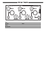
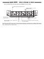
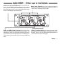
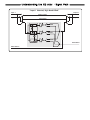
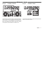
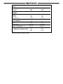
English V1.01
Band Kill Effects Owner’s Manual
CAUTION
RISK OF ELECTRIC SHOCK
DO NOT OPEN
A T T E N T I O N : RISQUE DE CHOC ELECTRIQUE - NE PAS OUVRIR
W A R N I N G : TO REDUCE THE RISK OF FIRE OR ELECTRIC
SHOCK DO NOT EXPOSE THIS EQUIPMENT TO RAIN OR MOISTURE
The lightning flash with arrowhead symbol, within an equilateral triangle, is
intended to alert the user to the presence of uninsulated ‘dangerous voltage’
within the product’s enclosure that may be of sufficient magnitude to constitute a risk of electric shock to persons.
The exclamation point within an equilateral triangle is intended to alert the
user to the presence of important operating and maintenance (sevicing)
instructions in the literature accompanying the product.
INSTRUCTIONS PERTAINING TO A RISK OF FIRE, ELECTRIC SHOCK, OR INJURY TO PERSON
IMPORTANT SAFETY INSTRUCTIONS READ AND SAVE THESE INSTRUCTIONS
This product may be equipped with a polarized line plug ( one blade wider
than the other). This is a safety feature. If you are unable to insert the plug
into the outlet, contact an electrician to replace your obsolete outlet, Do not defeat the safety purpose of the plug. For the USA
For Canada
For Polarized Line Plug:
Caution: TO PREVENT ELECTRIC SHOCK, MATCH WIDE
BLADE OF PLUG TO WIDE SLOT, FULLY INSERT.
Attention: POUR …VITER LES CHOCS …LECTRIQUES, INTRODUIRE LA
LAME LA PLUS LARGE DE LA FICHE DANS LA BORNE CORRESPONDANTE
DE LA PRISE ET POUSSER JASQUí AU FOND.
For the U.K.
IMPORTANT: THE WIRES IN THIS MAINS LEAD ARE
COLOURED IN ACCORDANCE WITH THE FOLLOWING CODE:
BLUE: NEUTRAL
BROWN: LIVE
As the colours of the wires in the mains lead of this apparatus may not correspond
with the coloured markings identifying the terminals in your plug, proceed as follows.
The wire which is coloured BLUE must be connected to the terminal which is marked
with the letter N or coloured BLACK. The wire which is coloured BROWN must be
connected to the terminal which is marked with the letter L or coloured RED. Under
no circumstances must either of the above wires be connected to the earth terminal of
the three pin plug.
Double Insulation: When servicing use only identical replacement parts.
WARNING - When using electric products, basic precautions should always be taken, including the following:
1. Read all the instructions before using the product.
2. Do not use this product near water - for example near a bathtub,
washbowl, kitchen sink, in a wet basement, or near a swimming pool,
or the like.
3. This product should be used only with a cart or stand that is
recommended by the manufacturer.
4. This product, either alone or in combination with an amplifier and
headphones or speakers, may be capable of producing sound levels that could cause permanent
hearing loss. Do not operate for long period of time at high volumeor at an uncomfortable level. If
you experience any hearing loss or ringing in the ears, consult an audiologist.
5. This product should be located with sufficient air space for proper ventilation.
6. The product should be located away from heat sources such as
radiators, heat registers, or other products (including amplifiers) that
produce heat.
7. Clean only with a damp cloth. Before cleaning the unit, turn off the power and unplug the power
cord from the outlet.
8. The power supply cord of the product should be unplugged from the wall outlet during lightning
storms or when left unused for a long periods of time.
9. Use only with attachments/accessories specified by the manufacturer.
10. The product should be serviced by qualified service personnel when:
A. The power supply cord or the plug has been damaged; or
B. Objects have fallen, or liquids has been spilled into the product; or
C. The product has been exposed to rain; or
D. The product does not appear to be operate normally or exhibits a
marked change in performance; or
E. The product has been dropped, or the enclosure damaged.
11. Do not attempt to service the product beyond what has been described in the user maintenance instructions. All other servicing should be referred to qualified service personnel.
Table of Contents
Introduction . . . . . . . . . . . . . . . . . . . . . . . . . . . . . . . . . . . . . . . . . . . . . . . . . . .5
Quick Start . . . . . . . . . . . . . . . . . . . . . . . . . . . . . . . . . . . . . . . . . . . . . . . . . . . .6
What to Connect Where . . . . . . . . . . . . . . . . . . . . . . . . . . . . . . . . . . . . . . . .6
A First Look at the Controls . . . . . . . . . . . . . . . . . . . . . . . . . . . . . . . . . . . . . .7
Understanding the EQ Killer . . . . . . . . . . . . . . . . . . . . . . . . . . . . . . . . . . . . . . .8
Front Panel . . . . . . . . . . . . . . . . . . . . . . . . . . . . . . . . . . . . . . . . . . . . . . . . . .8
Back Panel . . . . . . . . . . . . . . . . . . . . . . . . . . . . . . . . . . . . . . . . . . . . . . . . . .9
Signal Flow . . . . . . . . . . . . . . . . . . . . . . . . . . . . . . . . . . . . . . . . . . . . . . . . .10
Performance Guide . . . . . . . . . . . . . . . . . . . . . . . . . . . . . . . . . . . . . . . . . . . . .11
Artist Applications . . . . . . . . . . . . . . . . . . . . . . . . . . . . . . . . . . . . . . . . . . . . . .14
Specifications . . . . . . . . . . . . . . . . . . . . . . . . . . . . . . . . . . . . . . . . . . . . . . . . .16
Saftey & Conformity . . . . . . . . . . . . . . . . . . . . . . . . . . . . . . . . . . . . . . . . . . . .17
Inventory INSPECTION:
The uniquely styled Electrix carton should contain:
• Electrix EQ Killer
• EQ Killer User Manual
• Rackmount kit (shipped attached to product)
• Warranty Card
• Power Transformer (as appropriate for your region)
• Electrix Joiner Plate (joins two "Mods" together!)
Note: If any of the above are missing, please inform your local Electrix distributor, agent or dealer immediately.
English... 3
Settings Template
Title:
Session:
Artist:
Description:
Date:
Introduction
Welcome to Electrix! We would like to thank you for purchasing EQ Killer, a customizable Kill Box for DJ’s and producers. EQ
Killer represents an entirely new concept in musical electronics,
unique in both its "hands on" ease of use and "retro/futuristic"
design.
EQ Killer’s unique industrial design allows it to be used in a 10"
rack mount or as a desktop tool. We’ve even included a joiner
plate to connect two Mod products together to fit in a 19" rack.
This new concept makes EQ Killer’s control surface perfect for
any use, whether live or in the studio. Check out the shape!
EQ Killer can directly process a wide range of input signal
sources from vinyl to CDs, as well as synthesizers, samplers, or
just about anything else in your rig.
For maximum flexibility, connect EQ Killer to other members of
the Electrix Mods family. For example, the Filter Queen is a
great sounding Analog HIGH Order Filter that offers DJs, musicians and producers the award winning quality of the Electrix
Filter Factory in an even more cost effective package. Also,
check out the Electrix MoFx for distortion, phasor and delay, as
well as the Electrix Warp Factory for vocal effects and vocoding.
EQ Killer boasts three frequency bands with level controls and
frequency selection for maximum "Performance EQ." The dual
path architecture allows easy switching between two turntables
or line level devices to individually access EQ Killer’s band killing
or boosting effect. There’s even a stereo send and return loop
so you can apply external effects to the "killed" bands!
A New Dimension in FX!
EQ Killer is part of a new series of remix tools from Electrix
called the "Mods." Like the Modular Synthesizers of the 1960’s
and 1970’s, multiple "Electrix Mods" can be racked together to
create a "hands on" effects monster.
We want to know what YOU think about the future of remix,
and we would also like to hear what you can do with Electrix
gear. Please send your CDs, MDs, vinyl or cassettes to us at the
address on the back page of this manual.
Want to find out more about the Mods or other Electrix products? Check out our Web site at: www.electrixpro.com. Again,
thanks for purchasing EQ Killer. Now get your "Hands On" and
get creative!
English... 5
QUICK START • What to Connect to Where
Here is the simplest way to pass audio signals through EQ Killer and create effects:
Connect the Power Transformer here.
Connect turntables or other
audio inputs here.
Use this output to send a signal to an
effects processor.
Use this input to return a signal from an
effects processor.
Select phono or line input
level.
Use these line level outputs to connect to the mixer
or power amplifier.
Note: When using the FX send and return to an external FX unit, the EQ Killer no longer functions as a Kill Box. Instead, the EQ
Killer sends effected signal to another processor (such as an Electrix Filter Queen,) then returns the processed signal back to the EQ
Killer’s outputs along with the unaffected bands.
QUICK START • A First Look at the Controls
Momentary & Band Kill Buttons: The momentary buttons are used to "play" the band killing effect in time with the
music. The Band Kill buttons latch the Band Kill effect on or off.
When a Band Kill is latched on, its associated Momentary button
will turn it off and bypass the Band Kill effect.
Band Level Controls: Use these to adjust the volume of
each band. Band gain is at unity when the band level control is
returned to the notched position at 12:00.
LOW and HIGH X-Over Controls: The X-Over controls
Input 1/2 Select Switch: This switch selects which of the
allow you to customize the width of each band on EQ Killer. The
LOW X-Over control sets the frequency transition point where
the LOW band ends and the MID band starts. The HIGH X-Over
control defines where the MID band ends and the HIGH band
starts.
two signal paths is routed through the band killing circuitry of the
EQ Killer. If there is only one signal path through EQ Killer this
control will function like an effect bypass.
English... 7
Understanding the EQ Killer • Front Panel
Momentary & Band Kill
Buttons: The momentary buttons
Level (dB) -6
0
LOW, MID and HI Band Level Controls: This sets the
amount of the band to be introduced to the music. At the center dented position there is no change in the band signal level,
this is commonly known as "Unity gain". When a band has been
"Killed", the band level control sets the Effect send level for that
band. The Band Level controls allow for up to 6 dB of gain per
band. Take care to ensure that this can
XOVER
be reproduced by your sound system
without causing damage.
band and the bottom of the HIGH band. For example, you could
"kill" the LOW and MID Bands and tweak the HIGH X-Over control frequency to isolate a hihat. You could also eliminate a vocal
part by killing the MID band and using the LOW X-Over and
HIGH X-Over controls to focus the frequency range in on the
voice.
XOVER
Note: It is possible to overlap the
LOW X-Over and HIGH X-Over frequencies. When this is done the MID
Band controls are no longer effective.
-∞
In and Out Level LEDs: These
are used to "play" the band killing effect
LEDs help you set and monitor the
in time with the music. The Band Kill
optimal signal levels from your signal
buttons latch the Band Kill effect on or
sources as well as the outputs of EQ
off. Momentary buttons reverses the
Killer. The optimal setting occurs when
Band Kill state. If a Band Kill is latched
20Hz
Frequency
20kHz
the In and Out LEDs show mostly green
on, the Momentary will bypass the
with
periodic
peaks
of
red.
Band Kill effect. If the Band is not "killed", the Momentary will
"kill" the Band.
The Effect Send: Whenever a band has been killed it is sent
to the stereo Effect send on the back panel of EQ Killer. Use this
LOW X-Over & HIGH X-Over Controls: The X-Over
feature to send bands to an external effects unit for processing.
controls allow the width of each band to be customized. The
There are return jacks that sum in the effect signal with the active
LOW X-Over control sets the frequency that simultaneously
source.
defines the top of the LOW band and the bottom of the MID
band. The HIGH X-Over control defines the top of the MID
Understanding the EQ Killer • Back Panel
Power Input: This input will accept the Electrix MOD power
adapter only. The unit is active as soon as power is applied.
Phono/Line Switch: When connecting a turntable set this
switch to Phono. For all other inputs set the switch to Line. If
your unit is sounding distorted or too quiet check to make sure
this switch is in the correct position. Note: All line level inputs
and outputs on the EQ Killer are nominal at +4dBu.
RCA stereo Inputs 1 & 2: Connect the output of your
turntable, synth or CD player here. You can connect two line
level devices or turntables to EQ Killer at one time. Because EQ
Killer has"dual path" architecture, there is no internal mixing of
the two inputs; instead there is an output for each input. This
preserves the ability to cue each signal source individually on
your mixer.
The Effects Loop: When you use the EQ Killers FX Loop,
the "killed signal" gets sent to your external FX processor, then
returns back to the EQ Killer. The "killed" signal with effects is
then mixed back into the "unkilled" part of the original signal.
This way you can isolate an instrument, apply outboard effects to
it, then return that effected sound back to your mix.
• Connect a stereo cable from the EQ Killer FX Send
jacks to the inputs of your outboard effect processor.
• Connect the outputs of the effect processor to the
EQ Killer FX Return jacks.
Grounding Post: Connect the ground wire from your
turntable here.
Cable Strain Relief: The power supply cable can be looped
around this to prevent stress on the power entry jack.
RCA stereo Outputs 1& 2: Connect a stereo cable from
here to your mixer input channel. If you have two inputs connected to the EQ Killer you should connect both of EQ Killer’s
outputs to inputs on the mixer. Note that even though your
input may be from a turntable, EQ Killer’s outputs are line level
and should be connected to line level inputs on your mixer.
English... 9
Understanding the EQ Killer • Signal Path
“Input 1 Selected, High Band Killed”
Input 1
Output 1
(Bypass Path)
Input 2
Output 2
Input Select
LOW Kill
MID Kill
HIGH Kill
Crossover
Effect Return
Effect Send
Performance Guide
Set-up 1:
Pre Mixer- 2 Sources
In this setup the two sound sources are connected directly to
Inputs 1 & 2 respectively. The outputs are then fed to two channels on the mixer. This is advantageous in a live situation as EQ
Killer can be auditioned (cued) while the other source is playing.
Selecting Input 2 effectively bypasses the EQ Kill circuit.
Set-up 2:
Pre Mixer-1 Source
In this setup the sound source is connected directly to Input 1.
Output 1 is then fed to the mixer.
English... 11
Performance Guide
Set-up 3:
Post Mixer
This is a simple set-up for stereo processing of the entire mix.
Cueing is not possible with this setup, so use it only after extensive experimentation with the EQ Killer. Send from the outputs
of your mixer to Input 1 of EQ Killer. Set the phono/line switch
for Input 1 to line. Use Output 1 to send to your amplification.
Note: Switching to Input 2 now acts as a bypass, it will not cut the
signal.
Set-up 4:
Mixer
Effect Loop Sends and your DJ
Another simple technique is to connect the Stereo Effect Sends
of your EQ Killer to an extra input Channel on your DJ mixer.
This way, the "killed" bands will be available for fading and crossfading separately in your mix.
Performance Guide
Set-up 5:
Adding Outboard Effects Processors
It’s easy to add outboard effects to the
EQ Killer. In fact, the different Electrix
Mods are designed to be routed to each
other for complex modular processing.
Here’s an example of how to connect the
EQ Killer FX Loop to an Electrix Filter
Queen. You can use this setup to isolate
vocals or instruments on the EQ Killer,
then tweak the Filter Queen. This allows
you to filter sweep just the vocals without
effecting the surrounding lows or highs.
• Set up the in and out levels of the effect
unit for unity gain.
• Connect the EQ Killer Effect Outputs
to the Filter Queen Inputs.
• Connect the Filter Queen Outputs to
the EQ Killer Effect Inputs.
• Engage the Band Kill Buttons to route
the vocals to the Filter Queen.
• Use the Filter Queen to filter sweep
the Vocals.
English... 13
Artist Applications
Rhythm Simplifier
Kill all three bands and listen to the source though each band independently.
Adjust the frequency controls so that the LOW band controls the bass and kick
drum level. And the Hihat is isolated to the Hi Band. Now momentarily tap
each band like a drum machine to impose a simpler rhythm onto the music.
Effect Pronto
Kill the MID band and use the frequency controls to eliminate as much of the vocal
sound as possible. Insert an effects device, preferably an Electrix MO-FX (or two)
to the EQ Killer Effects Loop. Set the effect unit up to a harsh flanger or phaser,
maybe add some distortion. Now use the MID band level control to balance out
the level of the affected vocal. Reviving the MID band will bypass the effect unit.
Vocal Eliminator
Kill the MID band and use the frequency controls to eliminate as much of the
vocal sound as possible. That was too easy. You can smoothly cross fade the
vocal eliminator effect out by sweeping the LOW/MID frequency up while
sweeping the MID/hi frequency down until they overlap and the MID band signal is returned.
Artist Applications
HIGH Pass / LOW Pass Filter
Kill the LOW and Hi band. Now use the frequency control to band limit the
MID band. This is useful for all types of production - from voicing instruments
to creating LOW-fi sound to getting the famous "telephone" sound.
Basic Filter Sweep
Set the HIGH X-Over Frequency all the way to the top. "Kill" the HIGH band, and
then sweep the HIGH X-Over frequency through its range for filter sweeping
effects.
Basic Crossover
Kill the LOW Band. The Source output will now carry the MID/HI
signal and the Effect send will carry the LOW signals.
English... 15
Specifications
INPUT
Connectors:
Max Input Level:
Impedance:
RCA (Phono)
-20dBV
47KΩ
RCA (Line)
+18dBu
47KΩ
RCA
1KΩ
+18 dBu
RCA
1KΩ
+18 dBu
PHONO
>75db
<0.3%
10Hz-20.0kHz
RCA
>90db
<0.3%
10Hz-20.0kHz
VOLTAGE
100 V
120 V
230 V
240 V
FREQUENCY
50/60 Hz
60 Hz
50 Hz
50 Hz
OUTPUT
OUTPUTS
Connectors:
Impedance:
Max Output Level:
PERFORMANCE
Dynamic Range:
THD:
Frequency Response:
POWER CONSUMPTION 16 watts
USE ONLY WITH ELECTRIX
POWER SUPPLY MODEL TFR0028
Actual measurements are subject to change
Saftey and Conformity
This equipment has been tested and found to comply with the limits for a
class A digital device, pursuant to part 15 of the FCC rules.
These limits are designed to provide reasonable protection against harmful
interference in a residential installation.
This equipment generates, uses and can radiate radio frequency energy and,
if not installed and used in accordance with the instructions, may cause
harmful interference to radio communications. However, there is no guarantee that interference will not occur in a particular installation.
If this equipment does cause harmful interference to radio or television
reception, which can be determined by turning the equipment on and off,
the user is encouraged to try to correct the interference by one or more of
the following measures:
• Reorient or relocate the receiving antenna.
• Increase the separation between the equipment and the receiver.
• Connect the equipment into an outlet on a circuit different from that to
which the receiver is connected.
• Consult a qualified dealer or an experienced radio / TV technician for help.
The user may find the following booklet, prepared by the Federal
Communications Commission, helpful: “How to identify and Resolve
Radio/TV interference Problems.”
For the customers in Canada:
This Class B digital apparatus meets all requirements of the Canadian
Interference-Causing Equipment Regulations.
Cet appareil Numerique de la Classe B respecte toutes les exigences du
Reglement sur le materiel brouilleur du Canada.
Certificate of Conformity
Electrix, a div. of IVL Technologies Ltd., hereby declares on their own
responsibility that the following product:
Electrix EQ Killer
that is covered by this certificate and marked CE-label conforms with the
following standards:
• EN 60065 Safety requirements for mains operated Electronic and related apparatus for household and similar general use
• EN 55022: 1994 (Limits and Methods: ITE Disturbances)
• EN 55082-1: 1997 (Generic Immunity: Residential)
With reference to regulations in following directives:
72/23/EEC, 89/336/EEC as amended by directive 93/68/EEC
Issued in Victoria, February 15, 2000 by Brian Gibson, Executive VicePresident, Research and Development
This booklet is available from the US Government Printing Office,
Washington, DC 20402, USA. Stock No. 004-000-0034-4.
Caution:
You are cautioned that any change or modifications not expressly approved
in this manual could void your warranty.
English... 17