1
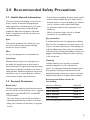
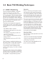
TIG 150/200 O P E R AT I N G M A N U A L Welcome to a better way of welding Congratulations on purchasing a MagMate™ TIG 150 or 200 welding machine. The products in BOC’s TIG range perform with reliability and have the backing of BOC’s national service network. This operating manual provides the basic knowledge required for TIG welding, as well as highlighting important areas of how to operate the MagMate TIG 150 & 200 machines. With normal use, and by following these recommended steps, your MagMate TIG 150 & 200 machine can provide you with years of trouble free service. BOC equipment and technical support is available through our national BOC Customer Service Centre or contact your local Gas & Gear outlet. Important Notice: This document has been prepared by BOC Limited ABN 95 000 029 729 (‘BOC’), as general information and does not contain and is not to be taken as containing any specific recommendation. The document has been prepared in good faith and is professional opinion only. Information in this document has been derived from third parties, and though BOC believes it to be reliable as at the time of printing, BOC makes no representation or warranty as to the accuracy, reliability or completeness of information in this document and does not assume any responsibility for updating any information or correcting any error or omission which may become apparent after the document has been issued. Neither BOC nor any of its agents has independently verified the accuracy of the information contained in this document. The information in this document is commercial in confidence and is not to be reproduced. The recipient acknowledges and agrees that it must make its own independent investigation and should consider seeking appropriate professional recommendation in reviewing and evaluating the information. This document does not take into account the particular circumstances of the recipient and the recipient should not rely on this document in making any decisions, including but not limited to business, safety or other operations decisions. Except insofar as liability under any statute cannot be excluded, BOC and its affiliates, directors, employees, contractors and consultants do not accept any liability (whether arising in contract, tort or otherwise) for any error or omission in this document or for any resulting loss or damage (whether direct, indirect, consequential or otherwise) suffered by the recipient of this document or any other person relying on the information contained herein. The recipient agrees that it shall not seek to sue or hold BOC or their respective agents liable in any such respect for the provision of this document or any other information. 2 Contents Welcome to a better way of welding 2 1.0 Recommended Safety Guidelines 4 2.0 Recommended Safety Precautions 5 2.1 Health Hazard Information 5 2.2 Personal Protection 5 2.3 Electrical Shock 7 2.4 User Responsibility 7 3.0Basic TIG Welding Techniques 8 3.1 GTAW (TIG) Welding 8 4.0Connecting your MagMate™ TIG 150 & 200 machine 10 4.1 Control Panel 10 4.2 For TIG Welding 10 4.3 TIG Welding Operation 10 4.4 Package Contents 12 5.0 Technical Specifications 13 6.0 Periodic Maintenance 14 7.1 Daily Maintenance 14 7.2Troubleshooting 14 7.0 Terms of Warranty 15 7.1 Terms of Warranty 15 7.2 Limitations on Warranty 15 3 1.0 Recommended Safety Guidelines Some safety precautions BOC recommends are as follows: •Repair or replace defective cables immediately. •Never watch the arc except through lenses of the correct shade. •In confined spaces, adequate ventilation and constant observation are essential. •Leads and cables should be kept clear of passageways. 4 •Keep fire extinguishing equipment at a handy location in the shop. •Keep primary terminals and live parts effectively covered. •Never strike an electrode on any gas cylinder. •Never use oxygen for venting containers. Diagram and safety explanation Diagram and safety explanation Electrical safety alert Wear dry, insulated gloves Welding electrode causing electric shock Insulate yourself from work and ground Fumes and gases coming from welding process Disconnect input power before working on equipment Welding arc rays Keep head out of fumes Read instruction manual Use forced ventilation or local exhaust to remove fumes Become trained Use welding helmet with correct shade of filter 2.0 Recommended Safety Precautions 2.1 Health Hazard Information The actual process of welding is one that can cause a variety of hazards. All appropriate safety equipment should be worn at all times, i.e. headwear, respiratory, hand and body protection. Electrical equipment should be used in accordance with the manufacturer’s recommendations. Eyes: The process produces ultra violet rays that can injure and cause permanent damage. Fumes can cause irritation. Skin: Arc rays are dangerous to uncovered skin. Inhalation: Welding fumes and gases are dangerous to the health of the operator and to those in close proximity. The aggravation of pre-existing respiratory or allergic conditions may occur in some workers. Excessive exposure may cause conditions such as nausea, dizziness, dryness and irritation of eyes, nose and throat. •Fumes from the welding of some metals could have an adverse effect on your health. Don’t breathe them in. If you are welding on material such as stainless steel, nickel, nickel alloys or galvanised steel, further precautions are necessary. •Wear a respirator when natural or forced ventilation is not good enough. Eye protection A welding helmet with the appropriate welding filter lens for the operation must be worn at all times in the work environment. The welding arc and the reflecting arc flash gives out ultraviolet and infrared rays. Protective welding screen and goggles should be provided for others working in the same area. Clothing Suitable clothing must be worn to prevent excessive exposure to UV radiation and sparks. An adjustable helmet, flameproof loose fitting cotton clothing buttoned to the neck, protective leather gloves, spats, apron and steel capped safety boots are highly recommended. 2.2 Personal Protection Recommended filter shades for arc welding Respiratory Less than 150 amps Shade 10* Confined space welding should be carried out with the aid of a fume respirator or air supplied respirator as per AS/NZS 1715 and AS/NZS 1716 Standards. 150 to 250 amps Shade 11* 250 to 300 amps Shade 12 300 to 350 amps Shade 13 Over 350 amps Shade 14 •You must always have enough ventilation in confined spaces. Be alert to this at all times. *Use one shade darker for aluminium •Keep your head out of the fumes rising from the arc. 5 Cylinder Safety Cylinder Valve Safety 1 Cylinder valve hand-wheel 2 Back-plug 3 Bursting disc Ensure cylinder value is closed before moving or disconnecting equipment. 1 Before operating a cylinder valve: 2 3 Back view of typical cylinder valve Operator wearing personal protective equipment (PPE) in safe position Ten Points about Cylinder Safety 1 Always read the labels and Safety Data Sheet (SDS) before use. 2 Store cylinders upright and use in well‑ventilated, secure areas away from pedestrian or vehicle thoroughfares. 3 Ensure cylinders are appropriately secured and guarded against being knocked violently or being allowed to fall. 4 Wear safety shoes, glasses and gloves when handling, connecting and using cylinders. 5 Ensure cylinders are appropriately restrained to mechanical lifting/handling devices prior to movement. 6 Keep in a cool, well-ventilated area, away from heat sources, sources of ignition and combustible materials, especially flammable gases. 7 Keep full and empty cylinders separate. 8 Keep ammonia-based leak detection solutions, oil and grease away from cylinders and valves. 9 10 6 When working with cylinders or operating cylinder valves, ensure that you wear appropriate protective clothing – gloves, boots and safety glasses. Never use force when opening or closing valves. Never repaint or disguise markings and damage on cylinders. If damaged, return cylinders to BOC immediately. •Ensure that the system you are connecting the cylinder into is suitable for the gas and pressure involved. •Cylinder valves should not be open unless a pressure regulator has been fitted. •Ensure that any accessories (such as hoses attached to the cylinder valve, or the system being connected to) are securely connected. A hose, for example, can potentially flail around dangerously if it is accidentally pressurised when not restrained at both ends. •Stand to the side of the cylinder so that neither you nor anyone else is in line with the back of the cylinder valve. This is in case a back-plug is loose or a bursting disc vents. The correct stance is shown in the diagram above. When operating the cylinder valve: •Open it by hand by turning the valve hand-wheel anti-clockwise. Use only reasonable force. •Ensure that no gas is leaking from the cylinder valve connection or the system to which the cylinder is connected. DO NOT use ammoniabased leak detection fluid as this can damage the valve. Approved leak detection fluid, can be obtained from a BOC Gas & Gear centre. •When finished with the cylinder, close the cylinder valve by hand by turning the valve hand-wheel in a clockwise direction. Use only reasonable force. Remember NEVER tamper with the valve. If you suspect the valve is damaged, DO NOT use it. Report the issue to BOC and arrange for the cylinder to be returned to BOC. • Parts that are broken, damaged, missing or worn should be replaced immediately. • Equipment should be cleaned periodically. BOC stocks a huge range of personal protective equipment. This, combined with BOC’s extensive Gas and Gear network, ensures fast, reliable service throughout the South Pacific. 2.3 Electrical Shock •Never touch ‘live’ electrical parts. •Always repair or replace worn or damaged parts. •Disconnect power source before performing any maintenance or service. •Earth all work materials. •Never work in moist or damp areas. Avoid electric shock by: PLEASE NOTE that under no circumstances should any equipment or parts be altered or changed in any way from the standard specification without written permission given by BOC. To do so, will void the Equipment Warranty. •Wearing dry insulated boots •Wearing dry leather gloves •Never changing electrodes with bare hands or wet gloves •Never cooling electrode holders in water •Working on a dry insulated floor where possible Further information can be obtained from Welding Institute of Australia (WTIA) Technical Note No.7 ‘Health and Safety Welding’ Published by WTIA, PO Box 6165 Silverwater NSW 2128 Phone (02) 9748 4443. •Never hold the electrode and holder under your arm. 2.4 User Responsibility • Read the Operating Manual prior to installation of this machine. • Always disconnect mains power before investigating equipment malfunctions. 7 3.0Basic TIG Welding Techniques 3.1 GTAW (TIG) Welding The Gas Tungsten Arc Welding – commonly referred to as Tungsten Inert Gas (TIG) – process uses the heat generated by an electric arc struck between a non-consumable tungsten electrode and the workpiece to fuse metal in the joint area and produce a molten weld pool. The arc area is shrouded in an inert or reducing gas shield to protect the weld pool and the non-consumable electrode. The process may be operated autogenously (without filler), or filler may be added by feeding a consumable wire or rod into the established weld pool. •The addition of filler is optional •Only inert or reducing gases can be used as the shielding gas •TIG welding is a high quality, versatile and commonly-used process •TIG is suitable for welding ferrous and nonferrous materials Operation Direct or alternating current power sources with constant current output characteristics are normally employed to supply the welding current. For DC operation, the tungsten may be connected to either output terminal, but is most often connected to the negative pole. The output characteristics of the power source can have an effect on the quality of the welds produced. Shielding gas is directed into the arc area by the welding torch, and a gas lens within the torch distributes the shielding gas evenly over the weld area. In the torch, the welding current is transferred to the tungsten electrode from the copper conductor. The arc is then initiated by one of several methods between the tungsten and the workpiece. Operating Modes The TIG process may be operated in one of the following modes: •Direct Current Electrode Negative (DCEN) •The TIG process can be run on DC-, DC+, or AC •Direct Current Electrode Positive (DCEP) The TIG process is capable of producing very high quality welds in a wide range of materials and in thicknesses up to about 8 or 10 mm. The mode used is largely dependent on the parent material being welded. It is particularly suited to welding of sheet material and for putting in the root run of pipe butt welds. The process tends to be very clean, producing little particulate fume, although it is capable of generating ozone in appreciable amounts and is not regarded as a high-productivity process. 8 •Alternating Current (AC) 1 2 3 4 5 6 7 Shielding gas Arc TIG filler rod Weld pool Collet Tungsten Electrode Workpiece 1 5 6 2 alloy and stainless steels, as well as nickel and titanium alloys. Copper alloys, with the exception of those containing aluminium in significant amounts, can also be welded with this polarity. DCEP is used for aluminium alloys when welding, with pure helium as the shielding gas, since this polarity has a strong cathodic cleaning effect capable of removing the tenacious aluminium oxide film from the surface. It may also be used for TIG welding magnesium alloys. 3 4 7 Schematic of the TIG welding process DC Electrode Negative (DCEN) In this mode the tungsten electrode is the negative pole in the welding circuit, the workpiece being the positive pole. DC Electrode Positive (DCEP) In this mode the tungsten electrode is the positive pole in the welding circuit, the workpiece being the negative pole. Alternating Current (AC) In this mode the polarity of the tungsten electrode and the workpiece alternate between negative and positive at the frequency of the applied welding current. Application AC polarity is used most commonly when welding aluminium and its alloys with pure argon or argon-helium mixtures to take advantage of the combination of the cyclic heating and cleaning action. It is also suitable for welding magnesium alloys and aluminium bronze. Applications •High quality fabrications in stainless steel •Aluminium, copper and nickel alloys •Welding reactive and refractory metals such as titanium, tantalum and zirconium The process is used extensively in the nuclear and aerospace industries and in the construction and maintenance of chemical and cryogenic process plant and pipework. It is also used for fabrication of tube heat-exchangers in petrochemical and power-generation plant, and for brewing and food-processing vessels. The TIG process is very versatile and may be used to weld any metal or alloy system over a wide range of thicknesses, but is usually restricted to 10mm and under for economic reasons. It is particularly suited to welding sheet materials and for the root run in pipe butt welds. TIG Welding Equipment DCEN is the most common mode of operation and is widely used for welding all carbon, •Gas supply system The equipment used for TIG welding consists of: •Power source •Welding torch •Tungsten electrode •Leads and connectors 9 4.0Connecting your MagMate™ TIG 150 & 200 machine 4.1 Control Panel 1 2 3 4 connected to the positive (+) output terminal. The amperage for welding can be adjusted by turning the weld current adjustment knob 5 . The duration of the post flow gas can be adjusted by turning the post flow gas adjustment knob (a longer post flow gas will result in better protection for the weld pool and TIG tungsten). 5 Connecting the shielding gas. Fit the supplied shielding gas regulator to the appropriate shielding gas cylinder ensuring safety steps are followed as outlined on page 6 of this manual. 6 1 2 3 4 5 6 7 8 9 7 8 9 Power switch Power indicator Overtemperature indicator Post flow gas adjustment Welding current adjustment Negative output terminal Gas output Contactor control Positive output terminal The machine needs to be placed in a wellventilated area ensuring that air vents are not covered. 4.2 For TIG Welding Connect the dinse connector of the supplied TIG torch to the machine’s negative output terminal 6 . The gas hose must be firmly connected to the gas output connector 7 and the contactor control must be connected to the contactor control socket on the machine 8 . The work return lead should be 10 Open the cylinder and set the required gas flow using the pressure adjustment knob on the regulator. 4.3 TIG Welding Operation The MagMate TIG 150 or 200 is fitted with a High Frequency (HF) start mode. The arc would be initiated by keeping a distance of 2-4 mm between the workpiece and the tungsten. The HF will be initiated by depressing the contactor switch. Once the arc is initiated, the HF will automatically turn off. 4.3.1 For Direct current (DC) TIG Welding Select the correct size and type of non‑consumable tungsten and shielding gas for the application. For (DC-) (most commonly used polarity) connect the TIG torch to the negative dinse plug connector and the work return lead to the positive dinse plug connector. Gas Cylinder Power Supply (1phase~AC240V) Connected to ground Earth Clamp TIG Torch Workpiece - + GTAW with DCEN produces deep penetration because it concentrates the heat in the joint area. No cleaning action occurs with this.The heat generated by the arc using this polarity occurs in the work thus a smaller electrode can be used as well as a smaller gas cup and gas flow.The more concentrated arc allows for faster travel speeds. For (DC+) applications connect the TIG torch to the positive dinse plug connector and the work return lead to the negative dinse plug connector. In this mode most of the heat is generated within the non-consumable tungsten and the heat input into the plate is reduced resulting in lower penetration depths. Larger tungstens are normally selected for this application. 11 4.4 Package Contents TIG 150 •TIG 150 Power source •TIG-17 torch, 4m •Regulator •Gas hose •Work clamp with cable (dinse connector) •Primary cable with plug (10 amp) •Operating manual TIG 200 •TIG 200 Power source •TIG-26 torch, 4m •Regulator •Gas hose •Work clamp with cable (dinse connector) •Primary cable with plug (15 amp) •Operating manual 12 5.0 Technical Specifications Model No. Part No. Power voltage (V) Frequency (Hz) Rated input current (A) TIG 150 TIG 200 MAGTIG150 MAGTIG200 Single phase AC 240V ±15% Single phase AC 240V ±15% 50/60 50/60 17 26 10–150 10–200 Rated working voltage (V) 16 18 No-load voltage (V) 46 48 Duty cycle (%) 40 40 No-load loss (W) 40 40 Arc initiation HF HF Efficiency (%) 80 80 Power factor 0.73 0.73 Output current (A) F F Housing protection grade Insulation grade IP21 IP21 Weight (kg) 8.0 8.0 400 x 153 x 291 400 x 153 x 291 Dimensions (mm) 13 6.0 Periodic Maintenance In maintenance of the unit, take into consideration the rate of use and the environment it is used in. When the unit is used properly and serviced regularly you will avoid unnecessary disturbances in use and production. 7.1 Daily Maintenance Perform the following maintenance daily: • Clean electrode holder and TIG torch’s gas nozzle. Replace damaged or worn parts. • Check TIG torch’s electrode. Replace or sharpen, if necessary. • Check tightness of welding and earth cable connections. • Check condition of mains and welding cables. • See that there is enough space in front of and back of the unit for ventilation. 7.2Troubleshooting Main switch signal light is not lit. Unit does not get electricity. • Check mains fuses. • Check mains cable and plug. Unit does not weld well. Arc is uneven and goes off. Electrode gets stuck in weld pool. • Check welding settings and adjust when necessary. • Check that earth clamp is properly fixed and that contact surface is clean and the cable is undamaged. 14 Signal light for overheating is lit. The unit has overheated. • Check that there is ample space in front of and back of the unit for ventilation. • Check welding settings. If problems in use are not solved with above mentioned measures, please contact your local BOC representative. 7.0 Terms of Warranty Warranty for MagMate™ TIG 150 or 200 7.1 Terms of W arranty BOC provides a warranty for the MagMate TIG 150 & 200 sold by it against defects in manufacture and materials. Machines under warranty will be exchanged and not repaired. •Valid for 18 months from date of purchase. •Freight, packaging and insurance costs are to be paid for by the claimant. •No additional express warranty is given unless in writing signed by an authorised manager of BOC. •This warranty is in addition to any other legal rights you may have. •Electrode holders and torches are not covered. 7.2 Limitations on Warranty The following conditions are not covered: •Non compliance with operating and maintenance instructions such as connection to incorrect faulty voltage supply including voltage surges outside equipment specs and incorrect overloading. • Natural wear and tear and accidental damage. • Transport or storage damage. The Warranty is void if: •Changes are made to the product without the approval of the manufacturer. • Repairs are carried out. 15 For more information on MagMate products or service, call the BOC Customer Service Centre on: AU S TRA L I A 131 262 Email: [email protected] Website: www.boc.com.au NEW Z EA L AN D 0800 111 333 Email: [email protected] Website: www.boc.co.nz MagMate™ is distributed by: BOC Limited ABN 95 000 029 729 10 Julius Avenue North Ryde, NSW 2113 AUSTRALIA BOC Limited 970 – 988 Great South Road Penrose, Auckland NEW ZEALAND BOC is a trading name of BOC Limited, a member of The Linde Group, © BOC Limited 2013. Reproduction without permission is strictly prohibited. Details given in this document are believed to be correct at the time of printing. Whilst proper care has been taken in the preparation, no liability for injury or damage resulting from its improper use can be accepted. MP12-0759 . FDAUS . 0813