1
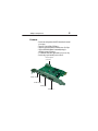
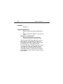
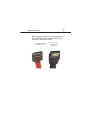
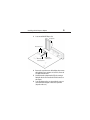
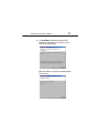
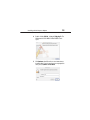
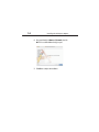
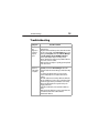
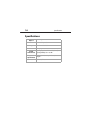
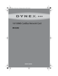
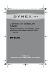
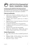
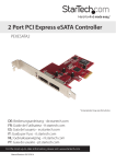
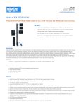
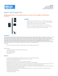
2-port eSATA II PCI Express
Adapter
DX-ESATAP
User G u id e
2
Contents
Dynex DX-ESATAP
2-port eSATA II PCI Express
Adapter
Contents
Important safety instructions ...................................3
Adapter components ................................................4
Features ....................................................................5
Installing the PCI Express adapter .............................8
Troubleshooting .....................................................15
Specifications .........................................................16
Legal notices ...........................................................17
One-year limited warranty .....................................18
Important safety instructions
3
Important safety instructions
• Always read the safety instructions and User Guide
carefully. Keep this User Guide for future reference.
• When using some operating systems, the driver software
must be installed prior to operation.
• Do not drop or allow forceful impacts to the product, or
install it in locations exposed to heavy vibrations.
• Do not disassemble or modify the product in any way.
Disassembly or modification may not only void warranty,
but could also cause damage or lead to fires or electric
shock.
• Do not use or store the product in damp locations. Liquid
entering the product may cause damage or lead to fires or
electric shock.
• Before removing the PCI Express adapter from its package,
safely discharge any static electricity build-up which may
damage the computer or the PCI Express adapter by
touching an unpainted piece of metal. Handle the card by
the metal mounting bracket and printed circuit board
edges only.
• Avoid touching the gold-plated PCIe connectors and the
internal electronic components.
• This product is for general computer use. It is not to be used
in equipment requiring exceptional reliability, particularly
when the breakdown or malfunction of this product may
jeopardize life or health (such as aerospace equipment,
atomic power control systems, traffic-related equipment,
transportation equipment, industrial robotics, combustion
equipment, various safety devices, and life-support
systems).
4
Adapter components
Adapter components
Package contents
•
•
•
•
2-port eSATA II PCI Express adapter
DC power cables (2)
Utility CD
Quick Setup Guide
5
Adapter components
Features
• Provides two independent Serial ATA channels and external
power ports
• Supports 1-lane 2.5 Gbps PCI Express
• Supports Serial ATA Generation II transfer rate of 3.0 Gbps
• Support SATA II NCQ (Native Command Queuing) to
maximize system performance
• 31 commands and scatter/gather tables per port on-chip
• Provides large 4-pin internal power connector
Internal power
connector
5V DC output
5V DC output
eSATA port
eSATA port
6
Adapter components
Interface
• PCI Express bus
System requirements
• PCI Express-enabled system with an available PCI Express
slot
• Windows XP, Windows Vista, Windows 7, or Mac 10.4.x and
above
Using the correct eSATA cable
Note: Make sure that you have the correct eSATA cable to
connect your external SATA device to the PCI Express adapter.
There are two types of SATA cables available, which are used for
different applications. The internal SATA type A cable has an
L-shaped key on each plastic plug. This type of cable is used with
an internal SATA port to connect an internal SATA drive.
The external eSATA cable has a shielded plug, which does not have
an L- shaped key. The eSATA cable is designed to connect an
external SATA device, so it must therefore provide better EMI
(electromagnetic interference) and ESD (electrostatic discharge)
prevention. This type of cable is capable of a fast data transfer rate
of up to 300 MB/s.
7
Adapter components
The following picture can help you to recognize both standard
SATA and eSATA cables. If you do not have an eSATA cable, you
must purchase one from your local dealer.
Use this connector
SATA type A cable (has
an L-shaped key)
eSATA cable (no
L-shaped key)
8
Installing the PCI Express adapter
Installing the PCI Express adapter
Installing the hardware
Caution: Before touching any electronic components, make
sure that you first touch an unpainted, grounded metal object
to discharge any static electricity stored on your clothing or
body.
Caution: Handle the PCI Express adapter by the metal
mounting bracket and the printed circuit board edges only.
Avoid touching the gold-plated PCIe connector and the
internal electronic components.
Note: Opening your computer's case may void your computer's
warranty. Contact your computer's manufacturer before
opening the case to make sure that you do not void the
warranty.
To install the PCI Express adapter:
1 Turn off your computer and unplug the power cord and all
cables.
2 Open your computer case. See your computer's user guide
for information about removing the cover.
9
Installing the PCI Express adapter
3 Locate an available PCI Express slot.
Backplate
PCI connectors
PCI Express
connector, X1
PCI Express
connector, X16
4 Remove the screw that secures the backplate, then remove
the backplate. If your computer case is tooless, refer to the
User Guide for instructions.
5 Carefully insert the adapter into the PCIe slot, seating it
firmly into the slot. Do not touch the PCIe bus contacts on
the adapter.
6 Secure the adapter to the case using either the screw you
removed from the backplate or the tooless equivalent
(depends on the case).
10
Installing the PCI Express adapter
7 Connect an available 4-pin power plug from your computer
power supply to the PCI Express adapter’s JP1 power
connector.
8 Close your computer's case.
9 Plug in the power cord and other cables, then turn on your
computer.
Installing the software
Windows OS driver Installation
To install the Windows driver:
1 Save all files and close all programs.
2 If you install the adapter first, your PC will detect the
adapter and the Found New Hardware Wizard opens. If that
happens, click Cancel.
3 Insert the included utility CD into your CD drive. The first
driver installation utility page opens automatically.
Installing the PCI Express adapter
11
4 Click Install Driver. The Welcome to the Dynex eSATA
adapter Driver Setup Wizard opens. Follow the on-screen
instructions to install the driver.
When the installation is complete, the Installation Complete
dialog box opens.
12
Installing the PCI Express adapter
5 Click Close to complete the driver installation.
6 To verify the driver installation, right-click the My
Computer icon on your desktop, then click Properties.
7 Click Device Manager, then double-click Silicon Image
Sil 3132 SATALink Controller. The message “This device
is working properly” is displayed, confirming that the driver
has been correctly installed.
MAC OS driver installation
To install the driver in Macintosh OS 10.4.x or later:
1 Save all files and close all programs.
2 Insert the included utility CD into your CD drive. The first
driver installation utility page opens automatically.
3 Click Exit, then locate and open the “Mac driver” folder.
Installing the PCI Express adapter
13
4 Double-click the Sil3132_1.1.9u_sil_Pkg.pkg file. The
Welcome to the Sil3132 Mac OS X Driver Installer screen
opens.
5 Click Continue, then follow the on-screen instructions to
install the driver. Several screens later you are prompted to
enter your (user)Name and Password.
14
Installing the PCI Express adapter
6 Enter your default (user)Name and Password, then click
OK. The Successful Installation dialog box opens.
7 Click Close to complete the installation.
15
Troubleshooting
Troubleshooting
Symptom
Possible Solution
The Windows
Device
Manager does
not show the
PCI Express
adapter
• Make sure that the PCI Express adapter is correctly installed
in the PCIe slot.
• Repeat the driver installation procedure, then make sure that
the device exists. Right-click the My Computer icon on your
desktop, click Properties, then click the Device Manager.
If the Silicon Image Sil 3132 SATALink Controller is
shown, the PCI Express adapter is working correctly.
• Remove the PCI Express adapter and try a different PCIe slot
in case there is a device conflict.
• Make sure that your computer's operating system is updated
to the latest version.
An eSATA
peripheral is
not detected by
the computer
Right-click the My Computer icon on your desktop, click
Properties, then click the Device Manager. If the SATA
peripheral is listed in the Device Manager, it should be working
correctly.
If it is shown as an unknown device, the cause may be a
defective eSATA peripheral or its software drivers. Do the
following:
• Check the eSATA connection and try a different eSATA cable.
• Check your SATA device's power source, and make sure that it
provides enough power for your SATA device to run stably.
Refer to the SATA peripheral’s user guide for the power
supply specifications.
• Uninstall your SATA device, then reinstall the SATA device
driver.
• Make sure that the SATA device is using a current driver. You
can download current driver software from the
manufacturer's Web site.
16
Specifications
Specifications
Chipset
Silicon Image 3132
Interface
One-lane PCI Express bus
Power port
External: 2 × Ø1.3 DC Jack
Internal
1 × 4-pin power connector
System
environment
Operating temperature: 41°F~104°F (5°C~40°C)
Operating humidity: 20%~80% RH
Windows XP, Windows Vista, Windows 7, Mac 10.4.x
System
requirements or higher
Certification
FCC Class B, ICES-003
Legal notices
17
Legal notices
FCC Part 15
This device complies with Part 15 of the FCC Rules. Operation of this product is
subject to the following two conditions: (1) this device may not cause harmful
interference, and (2) this device must accept any interference received, including
interference that may cause undesired operation.
This equipment has been tested and found to comply within the limits for a class
B digital device, pursuant to Part 15 of the FCC Rules. These limits are designed to
provide reasonable protection against harmful interference in a residential
installation. This equipment generates, uses, and can radiate radio frequency
energy and, if not installed and used in accordance with the instructions, may
cause harmful interference to radio communications. However, there is no
guarantee that interference will not occur in a particular installation. If this
equipment does cause harmful interference to radio or television reception,
which can be determined by turning the equipment off and on, the user is
encouraged to try to correct the interference by one or more of the following
measures:
• Reorient or relocate the receiving antenna.
• Increase the separation between the equipment and receiver.
• Connect the equipment into an outlet on a circuit different from that to
which the receiver is connected.
• Consult the dealer or an experienced technician for help.
Canada ICES-003 statement
This Class B digital apparatus complies with Canadian ICES-003.
Notices
Specifications and features are subject to change without notice or obligation.
For service and support call (800) 305-2204.
18
One-year limited warranty
One-year limited warranty
Dynex Products (“Dynex”) warrants to you, the original purchaser of this new
DX-ESATAP (“Product”), that the Product shall be free of defects in the original
manufacture of the material or workmanship for a period of one (1) year from the
date of your purchase of the Product (“Warranty Period”). This Product must be
purchased from an authorized dealer of Dynex brand Products and packaged with
this warranty statement. This warranty does not cover refurbished product. If you
notify Dynex during the Warranty Period of a defect covered by this warranty that
requires service, terms of this warranty apply.
How long does the coverage last?
The Warranty Period lasts for one year (365 days) from the date you purchased the
Product. The purchase date is printed on the receipt you received with the
Product.
What does this warranty cover?
During the Warranty Period, if the original manufacture of the material or
workmanship of the Product is determined to be defective by an authorized
Dynex repair center or store personnel, Dynex will (at its sole option): (1) repair
the Product with new or rebuilt parts; or (2) replace the Product at no charge with
new or rebuilt comparable products or parts. Products and parts replaced under
this warranty become the property of Dynex and are not returned to you. If service
of products and parts are required after the Warranty Period expires, you must pay
all labor and parts charges. This warranty lasts as long as you own your Dynex
Product during the Warranty Period. Warranty coverage terminates if you sell or
otherwise transfer the Product.
How to obtain warranty service?
If you purchased the Product at a retail store location, take your original receipt
and the Product to the store you purchased it from. Make sure that you place the
Product in its original packaging or packaging that provides the same amount of
protection as the original packaging. If you purchased the Product from an online
web site, mail your original receipt and the Product to the address listed on the
web site. Make sure that you put the Product in its original packaging or
packaging that provides the same amount of protection as the original packaging.
One-year limited warranty
19
To obtain in-home warranty service for a television with a screen 25 inches or
larger, call 1-888-BESTBUY. Call agents will diagnose and correct the issue over
the phone or will have an Dynex-approved repair person dispatched to your
home.
Where is the warranty valid?
This warranty is valid only to the original purchaser of the Product in the United
States, Canada, and Mexico.
What does the warranty not cover?
This warranty does not cover:
• Customer instruction
• Installation
• Set up adjustments
• Cosmetic damage
• Damage due to acts of God, such as lightning strikes
• Accident
• Misuse
• Abuse
• Negligence
• Commercial use
• Modification of any part of the Product
• Plasma display panel damaged by static (non-moving) images applied
for lengthy periods (burn-in).
This warranty also does not cover:
• Damage due to incorrect operation or maintenance
• Connection to an incorrect voltage supply
• Attempted repair by anyone other than a facility authorized by Dynex to
service the Product
• Products sold as is or with all faults
• Consumables, such as fuses or batteries
• Products where the factory applied serial number has been altered or
removed
20
One-year limited warranty
REPAIR REPLACEMENT AS PROVIDED UNDER THIS WARRANTY IS YOUR EXCLUSIVE
REMEDY. DYNEX SHALL NOT BE LIABLE FOR ANY INCIDENTAL OR CONSEQUENTIAL
DAMAGES FOR THE BREACH OF ANY EXPRESS OR IMPLIED WARRANTY ON THIS
PRODUCT, INCLUDING, BUT NOT LIMITED TO, LOST DATA, LOSS OF USE OF YOUR
PRODUCT, LOST BUSINESS OR LOST PROFITS. DYNEX PRODUCTS MAKES NO OTHER
EXPRESS WARRANTIES WITH RESPECT TO THE PRODUCT, ALL EXPRESS AND
IMPLIED WARRANTIES FOR THE PRODUCT, INCLUDING, BUT NOT LIMITED TO, ANY
IMPLIED WARRANTIES OF AND CONDITIONS OF MERCHANTABILITY AND FITNESS
FOR A PARTICULAR PURPOSE, ARE LIMITED IN DURATION TO THE WARRANTY
PERIOD SET FORTH ABOVE AND NO WARRANTIES, WHETHER EXPRESS OR IMPLIED,
WILL APPLY AFTER THE WARRANTY PERIOD. SOME STATES, PROVINCES AND
JURISDICTIONS DO NOT ALLOW LIMITATIONS ON HOW LONG AN IMPLIED
WARRANTY LASTS, SO THE ABOVE LIMITATION MAY NOT APPLY TO YOU. THIS
WARRANTY GIVES YOU SPECIFIC LEGAL RIGHTS, AND YOU MAY ALSO HAVE OTHER
RIGHTS, WHICH VARY FROM STATE TO STATE OR PROVINCE TO PROVINCE.
Contact Dynex:
For customer service please call 1-800-305-2204
www.dynexproducts.com
Distributed by Best Buy Purchasing, LLC
7601 Penn Avenue South, Richfield, Minnesota, U.S.A. 55423-3645
© 2010 BBY Solutions, Inc.
All rights reserved. DYNEX is a trademark of BBY Solutions, Inc. Registered in some
countries. All other products and brand names are trademarks of their respective
owners.
One-year limited warranty
21
www.dynexproducts.com (800) 305-2204
Distributed by Best Buy Purchasing, LLC
7601 Penn Ave. South, Richfield, MN 55423 U.S.A.
© 2010 BBY Solutions, Inc.
All rights reserved.
DYNEX is a trademark of BBY Solutions, Inc. Registered in some countries. All
other products and brand names are trademarks of their respective owners.
10-1035
ENGLISH