1
SINAMICS S120 AC Drive
SINAMICS S120 AC Drive –
SINAMICS S120 AC Drives – a building block
for integrated drive solutions
SINAMICS S120 is a modular drive system with servo and Vector Control and is the SINAMICS product which is most suitable
for demanding drive applications in the fields of mechanical
and plant engineering. The SINAMICS S120 AC Drives especially supplement the DC/AC units with a central power infeed
and a DC link in types Booksize and Chassis for multi-axis
applications. Optimally tailored integrated solutions can be
designed for any type of application based on this building
block system.
The ready-to-connect SINAMICS single drive
with integrated power infeed
SINAMICS S120 AC Drives are designed for single-axis applications but can also be used for multi-axis applications. This
means that it is just as easy to find reliable solutions for positioning tasks for single axes as it is for synchronism and motion control tasks. In multi-axis applications with spatially distributed drives, distributed solutions based on SINAMICS S120
AC Drives offer a practical alternative to a central drive solution with a central infeed and a DC link thanks to the integrated power infeed.
Universally implementable
SINAMICS S120 AC Drives can easily be implemented in conjunction with higher-level automation systems using field bus
interfaces and the standardized PROFIdrive profile. Solutions
to standard positioning tasks – especially in the SIMATIC
environment – can therefore be found using SINAMICS S120
AC Drives even without in-depth knowledge of drives.
Because it is so easy to combine SINAMICS S120 AC Drives
with other SINAMICS S120 units, multi-axis groupings can be
extended comfortably and economically.
Modular machine components can thus be adapted to high
levels of integration and flexibility in line to varying customer
requirements.
Flexibility through modularity
Every SINAMICS S120 AC Drive consists of a Power Module
which includes a power infeed, a power control and an
optional filter.
If the AC Drive is operated as a single-axis drive combined with
a higher-level control, a Control Unit (e.g. CU310 DP) is added
to the Power Module. It contains the entire control intelligence for the drive, including positioning functions and the
field bus interface.
If the AC Drive is combined with other SINAMICS S120 products as part of a drive solution, a Control Unit adapter is
added to the Power Module in order to connect the AC Drive
to a higher-level Control Unit (e.g. CU320 for multi-axis
control) via the DRIVE-CLiQ interface in accordance with the
SINAMICS S120 system architecture.
2
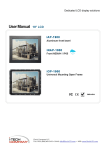
Controller
SINAMICS S120
AC Drive
with CU310
230 V 1 AC or 400 V 3 AC
Synchronous/
asychronous motor
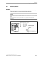
Figure 1: SINAMICS S120 AC Drive connected to a higher-level control
CUA31
CUA31
CUA31
SINAMICS S120 AC Drives
with CUA31
SINAMICS S120 Booksize grouping with CU320
Figure 2: 3 SINAMICS S120 AC Drives connected to a SINAMICS S120
multi-axis grouping
SINAMICS S120 AC Drive
CU310 Control Unit
The use of SINAMICS S120 AC Drives in single-axis applications connected to a higher-level control is illustrated in
Figure 1. Each of the AC Drives is equipped with a CU310
Control Unit. This unit contains the field bus interface for connecting to the higher-level control. CU310 DP with a PROFIBUS
DP connection or CU310 PN with an integrated Profinet interface can be selected. In both cases communication between
the control and the drive takes place in accordance with the
standardized PROFIdrive profile.
CU310 offers functions ranging from the simple speed controller to full positioning functionality.
Drive-related inputs/outputs can easily be linked in the CU by
means of BICO technology. This permits the greatest possible
separation of drive and higher-level control.
Various types of drive-related inputs/outputs and encoders are
connected easily via the DRIVE-CLiQ interface.
It is easy to implement safety systems using integrated safety
functions such as "Safe standstill" (SH) and "Safe brake control" (SBC).
CUA31 Control Unit adapter
It is also possible to use SINAMICS S120 AC Drives in multi-axis
applications. The drive is connected to a CU320 Control Unit
via the DRIVE-CliQ interface using the CUA31 Control Unit
adapter. The Control Unit then takes over control of the drive
functions for the AC drive. SIMOTION D modules can be used
as a Control Unit for motion control applications which go
beyond the scope of positioning tasks.
SINAMICS S120 AC Drives can also be used in hybrid operation
with SINAMICS S120 multi-axis units in this constellation. This
provides maximum flexibility for the use of SINAMICS S120
units.
CU310 Control Unit (left)
CUA31 Control Unit adapter (right)
Standardized, comfortable engineering
with SIZER and STARTER
As with all SINAMICS drives, the SIZER configuring tool helps
you to select the optimal drive configuration for your application. Graphical support and wizards efficiently guide you
through the selection of necessary components based on your
application.
SINAMICS S120 AC Drives are commissioned using STARTER,
the commissioning tool for the SINAMICS family. Electronic
rating plates ensure automatic and error-free preconfiguration of the drive system. Automatic optimization is a simple
way of optimizing the control response. It ensures fast and
reliable commissioning of the drives.
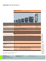
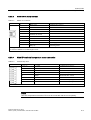
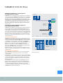
SINAMICS S120 Power Modules
The frame size of the Power Modules depends on the power
output.
We differentiate between block size and chassis units, which
are available in various frame sizes.
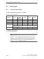
SINAMICS S120 AC Drives – Power Modules
Blocksize units
Chassis units
Frame size
A
B
C
D
E
F
FX
GX
230 V 1 AC (kW)
(HP)
0.25 – 1.1
(0.34 – 1.5)
–
–
–
–
–
–
–
400 V 3 AC (kW)
(HP)
0.37 – 1.5
(0.5 – 2)
2.2 – 4
(3 – 5)
7.5 – 15
(10 – 20)
18.5 – 30
(25 – 40)
37 – 45
(50 – 60)
55 – 90
(74 – 121)
110 – 132
(147 – 177)
160 – 250
(214 – 335)
3
SINAMICS S120 AC Drive
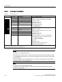
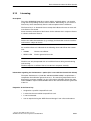
SINAMICS S120 AC Drive
Modular drive system for demanding single/multi-axis applications
Blocksize design
Chassis design
IP20
Supply voltages Vsupply/Power ratings
• 230 V 1 AC
• 380 – 480 V 3 AC
0.25 – 1.1 kW (0.3 – 1.5 HP)
0.37 – 90 kW (0.5 – 121 HP)
–
110 – 250 kW
(147 – 335 HP)
Technological functions
Flying restart, restart, kinetic buffering, positioning, BICO technology,
Motion Control (in connection with SIMOTION)
Safety functions
Safe standstill (SH),
Safe brake control (SBC)
Tools
SIZER for configuring, STARTER for commissioning
Typical application technologies
High-performance single drives
Safe standstill (SH)
Continuous motion control; continuous material webs; setpoint cascades; positioning; coordinated,
highly dynamic motion control of several axes via position; cross-axis motion control functionality using
SIMOTION (synchronism, electronic cam disks, ...)
Numerical control in machine tools in conjunction with SINUMERIK solution line
Communication interface
PROFIBUS DP, PROFINET 1)
Line frequency
47 – 63 Hz
Output voltage
0 ... Vsupply
Output frequency
Vector control: 0 – 300 Hz, Servo control: 0 – 650 Hz
Control principle
• V/f control
• Vector Control with/without encoder
• Servo Control with/without encoder
Yes
Yes
Yes
Motors
• Asynchronous
• Synchronous
• Torque
• Linear
Yes
Yes
Yes
Yes
Control dynamics
• Rise time of speed control
Vector Control:
• Rise time of torque control
Servo Control:
Vector Control:
25 ms without encoder, 11 – 15 ms with encoder
or 2.1 ms with int. acceleration pre-control,
1.1 ms (with 125 µs current controller clock cycle)
approx. 1 ms, Servo control: approx. 0.6 ms
1) Available soon.
For further information on SINAMICS S120, go to:
www.siemens.com/sinamics-S120
Siemens AG
Automation and Drives
Motion Control Systems
Postfach 3180, 91050 ERLANGEN
GERMANY
Order No. 6ZB5471-0AF02-0BA0
Printed in Germany
09405/622 224 VOG 1105 10.0
© Siemens AG 2005
Subject to change without notice
velopment of the products. An obligation to
provide the respective characteristics shall
exist only if expressly agreed in the terms of
contract.
AC/AC unit, modular
Degree of protection
The information provided in this brochure
contains merely general descriptions or performance characteristics which in case of actual use do not always apply as described or
which may change as a result of further de-
Drive type
Control Units
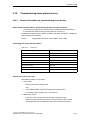
6.2 Control Unit CU310 DP (PROFIBUS)
6.2
6.2.1
6.2
Control Unit CU310 DP (PROFIBUS)
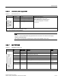
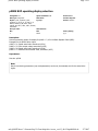
Description
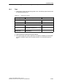
The Control Unit 310 DP (PROFIBUS) is the component in which the open-loop and closedloop control functions of a drive are implemented.
The CU310 DP has the following interfaces (ports):
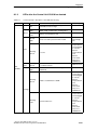
Table 6-1
Overview of the CU310 interfaces
Type
Number
Digital inputs
4
Digital inputs/outputs
4
DRIVE-CLiQ interfaces
1
PROFIBUS interface
1
Serial interface (RS232)
1
Power Module Interface (PM-IF)
1
Encoder interface (HTL/TTL)
1
EP terminals/
temperature sensor connection
1
24 V electronics power supply
1
Test sockets
3+1
Interface for BOP
1
Note
For test purposes, the fan also runs in the cold state at regular intervals.
Equipment Manual AC Drive
Manual, (GH6), 03/2006 Edition, 6SL3097-2AL00-0BP0
6-5
Control Units
6.2 Control Unit CU310 DP (PROFIBUS)
6.2.2
Safety information
Note
The CompactFlash card may only be inserted and removed from the Control Unit when in
the no-voltage condition.
Caution
The cooling clearances of 50 mm above and below the components must be observed. It is
not permissible that the connecting cables cover the cooling openings.
6-6
Equipment Manual AC Drive
Manual, (GH6), 03/2006 Edition, 6SL3097-2AL00-0BP0
Control Units
6.2 Control Unit CU310 DP (PROFIBUS)
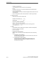
6.2.3
Interface description
6.2.3.1
Overview
3RZHU0RGXOH,QWHUIDFH30,)
;
6HULDOLQWHUIDFH
;
352),%86
6FUHZVKLHOGFRQQHFWLRQ
0IURP:HLGPíOOHUDQG
SURWHFWLYHFRQGXFWRUFRQQHFWLRQ
01P
$
;
(QFRGHULQWHUIDFH+7/77/
;
'5,9(&/L4LQWHUIDFH
;
(OHFWURQLFVSRZHUVXSSO\
7\SHSODWH
6ORWIRU
&RPSDFW)ODVKFDUG
;
(3WHUPLQDOV
WHPSHUDWXUHVHQVRUFRQQHFWLRQ
;
'LJLWDOLQSXWVRXWSXWV
6ORWIRU%23
770
WHVWVRFNHWV
/('V
5'<
&20
287!9
02'
5(6(7EXWWRQ
352),%86
DGGUHVVVZLWFK
Figure 6-3
Description of the CU310 DP interfaces (ports)
Equipment Manual AC Drive
Manual, (GH6), 03/2006 Edition, 6SL3097-2AL00-0BP0
6-7
Control Units
6.2 Control Unit CU310 DP (PROFIBUS)
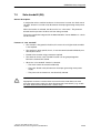
6.2.3.2
Sample connection
([W
9
0
;
0
0
˽
;
&8'3
;
;
(QFRGHULQWHUIDFH
9
0
0
9
0
6HULDOLQWHUIDFH
'5,9(&/L4VRFNHW
;
5['
352),%86
7['
;
0
QF
QF
0
30,)
3RUWV
7HPS
7HPS
QF
(39
(30
;
',
',
',
','2
','2
0
','2
','2
8VHVKLHOGHGFDEOHVIRUIDVWLQSXWV
-XPSHURSHQHOHFWULFDOLVRODWLRQIRUGLJLWDOLQSXWV',
&DQEHLQGLYLGXDOO\SDUDPHWHUL]HGDVLQSXWRXWSXW
5HTXLUHGIRUVDIHW\ಮ6DIH7RUTXH2))ಯ
8VHVKLHOGHGFDEOH
2QO\DGHYHORSPHQWLQWHUIDFH
6-8
0
Figure 6-4
',
0
287
0
&RPSDFW)ODVK
FDUG
Connection example CU310 DP
Equipment Manual AC Drive
Manual, (GH6), 03/2006 Edition, 6SL3097-2AL00-0BP0
Control Units
6.2 Control Unit CU310 DP (PROFIBUS)
6.2.3.3
X100 DRIVE-CLiQ interface
Table 6-2
DRIVE-CLiQ interface
Pin
Signal name
Technical specifications
1
TXP
Transmit data +
2
TXN
Transmit data -
3
RXP
Receive data +
4
Reserved, do not use
5
Reserved, do not use
6
RXN
7
Reserved, do not use
8
Reserved, do not use
A
+ (24 V)
Power supply
B
GND (0 V)
Electronic ground
Receive data -
Blanking plate for DRIVE-CLiQ interface: Molex, order number: 85999-3255
The maximum DRIVE-CLiQ cable length is 50 m.
6.2.3.4
X120 EP terminals / temperature sensor connection
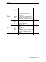
Table 6-3
Terminal strip X120
Terminal
Function
Technical specifications
1
Reserved, do not use
2
Reserved, do not use
3
M
Ground
4
+Temp
KTY or PTC input
5
-Temp
Ground for KTY or PTC
6
Reserved, do not use
7
EP +24 V
Safe standstill input (+)
8
EP M1
Safe standstill input (-)
Max. cross-section that can be connected 1.5 mm2
Notice
The KTY temperature sensor/the PTC must be connected with the correct polarity.
Equipment Manual AC Drive
Manual, (GH6), 03/2006 Edition, 6SL3097-2AL00-0BP0
6-9
Control Units
6.2 Control Unit CU310 DP (PROFIBUS)
6.2.3.5
X121 digital inputs/outputs
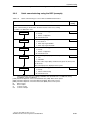
Table 6-4
Terminal strip X121
Terminal
Designation 1)
Technical specifications
1
DI 0
2
DI 1
3
DI 2
Voltage: -3 V to 30 V
Typical current consumption: 10 mA at 24 V DC
Isolation: The reference potential is terminal M1
4
DI 3
5
M1
6
M
7
DI/DO 8
As input:
8
DI/DO 9
9
M
Voltage: -3 V to 30 V
Typical current consumption: 10 mA at 24 V DC
10
DI/DO 10
11
DI/DO 11
Level (incl. ripple)
High level: 15 V to 30 V
Low level: -3 V to 5 V
12
M
Terminal numbers 8, 10, and 11 are "fast inputs"
Level (incl. ripple)
High level: 15 V to 30 V
Low level: -3 V to 5 V
Signal propagation times:
L → H approx. 50 μs
H → L: approx. 100 μs
Signal propagation times for inputs/”fast inputs”:
L → H: approx. 50 μs/5 μs
H → L: approx. 100 μs/50 μs
As output:
Voltage: 24 V DC
Max. load current per output: 500 mA
Continued-short-circuit-proof
Max. cross-section that can be connected: 1.5 mm 2
Type: Spring-loaded terminal 1 (see Appendix A)
1) DI: digital input; DI/DO: Bidirectional digital input/output; M: Electronic ground M1: Ground reference
Notice
An open input is interpreted as "low".
The "fast inputs" can be used in conjunction with a measuring system for position sensing.
To enable digital inputs (DI) 0 to 3 to function, terminal M1 must be connected. This can be
done as follows:
Connect the digital inputs' ground reference, or a jumper to terminal M. This removes the
electrical isolation for these digital inputs.
Note
An external 24 V power supply is required.
If a the 24 V power supply voltage is briefly interrupted, then the digital outputs are deactivated during this time.
6-10
Equipment Manual AC Drive
Manual, (GH6), 03/2006 Edition, 6SL3097-2AL00-0BP0
Control Units
6.2 Control Unit CU310 DP (PROFIBUS)
6.2.3.6
Electronics power supply X124
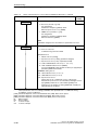
Table 6-5
Terminal block X124
Terminal
Function
Technical specifications
+
Electronics power supply
Voltage: 24 V DC (20.4 V - 28.8 V)
+
Electronics power supply
M
Electronic ground
Current consumption: max. 0.8 A
(without DRIVE-CLiQ or digital outputs)
M
Electronic ground
Max. current via jumper in connector:
20 A at 55 °C
Max. cross-section that can be connected: 2.5 mm2
Type: Screw terminal 2 (see Appendix A)
Note
The two “+” and “M” terminals are jumpered in the connector. This ensures the supply
voltage is looped through.
The current consumption increases by the value for the DRIVE-CLiQ node.
6.2.3.7
X21 PROFIBUS
Table 6-6
PROFIBUS interface X21
Pin
Signal name
Meaning
Range
1
-
Do not use
2
M24_SERV
Power supply for teleservice, ground
0V
3
RxD/TxD–P
Receive/transmit data P (B)
RS485
4
CNTR–P
Control signal
TTL
5
DGND
PROFIBUS data reference potential
6
VP
Supply voltage plus
5 V + -10 %
7
P24_SERV
Power supply for teleservice, + (24 V)
24 V (20.4 V 28.8 V)
8
RxD/TxD–N
Receive/transmit data N (A)
RS485
9
-
Do not use
Type: 9-pin SUB-D female
Equipment Manual AC Drive
Manual, (GH6), 03/2006 Edition, 6SL3097-2AL00-0BP0
6-11
Control Units
6.2 Control Unit CU310 DP (PROFIBUS)
Note
A teleservice adapter can be connected to the PROFIBUS interface (X21) for remote
diagnosis purposes.
The power supply for the teleservice terminals 2 and 7 withstands a max. load and continued
short-circuit current of 150 mA.
PROFIBUS connector
At the first and last node (device) in a line, the terminating resistors must be switched-in in
order to ensure disturbance/noise-free communications.
The terminating resistors are activated in the connector.
The cable shield must be connected at both ends over large-surface area contacts.
6.2.3.8
X23 HTL/ TTL encoder interface
Table 6-7
Encoder connection X23
Pin
Signal name
1
Reserved, do not use
Technical specifications
2
SSI_CLK
SSI clock, positive
3
SSI_XCLK
SSI clock, negative
4
PENC
Encoder power supply
5
PENC
Encoder power supply
6
PSENSE
Remote sense encoder power supply (P)
7
M
Electronic ground
8
Reserved, do not use
9
MSENSE
Remote sense encoder power supply (N)
10
RP
R track positive
11
RN
R track negative
12
BN
B track negative
13
BP
B track positive
14
AN_SSI_XDAT
A track negative / SSI data negative
15
AP_SSI_DAT
A track positive / SSI data positive
Type: 15-pin SUB D connector
6-12
Equipment Manual AC Drive
Manual, (GH6), 03/2006 Edition, 6SL3097-2AL00-0BP0
Control Units
6.2 Control Unit CU310 DP (PROFIBUS)
6.2.3.9
PROFIBUS address switches
Table 6-8
PROFIBUS address switches
Technical specifications
0
Significance:
21
2
3
4
5
Switch
Significance
S1
20 = 1
S2
21 = 2
ON
S3
22 = 4
OFF
S4
23 = 8
6
2 2 2 2 2
2
1 2 4 8 16 32 64
S1 S2 S3 S4 S5 S6 S7
Example:
1 + 4 +
32
PROFIBUS address
S5
24 = 16
= 37
S6
25 = 32
= 37
S7
26 = 64
Note
The PROFIBUS address switches are defaulted to 0 or 127. In these two settings,
addresses are assigned via parameters.
The address switch is behind the blanking plate. The blanking plate is part of the scope of
supply.
Setting the PROFIBUS address
The following reference contains further information about setting the PROFIBUS address:
Reference: /IH1/ SINAMICS S120 Commissioning Manual.
Equipment Manual AC Drive
Manual, (GH6), 03/2006 Edition, 6SL3097-2AL00-0BP0
6-13
Control Units
6.2 Control Unit CU310 DP (PROFIBUS)
6.2.3.10
X22 serial interface (RS232)
Table 6-9
Serial interface (RS-232-C) X140
Pin
Designation
Technical data
2
RxD
Receive data
3
TxD
Transmit data
5
Ground
Ground reference
Type: 9-pin SUB D connector
6.2.3.11
Measurement sockets T0, T1, and T2
Table 6-10
Measurement sockets T0, T1, and T2
Socket
Function
Technical specifications
T0
Measurement socket 0
T1
Measurement socket 1
T2
Measurement socket 2
Voltage: 0 V to 5 V
Resolution: 8 bits
Load current: max. 3 mA
Continued-short-circuit-proof
M
Ground
The reference potential is terminal M
The measurement sockets are only suitable for bunch pin plugs with a diameter of 2 mm.
6-14
Equipment Manual AC Drive
Manual, (GH6), 03/2006 Edition, 6SL3097-2AL00-0BP0
Control Units
6.2 Control Unit CU310 DP (PROFIBUS)
6.2.3.12
Slot for the CompactFlash card
Figure 6-5
Slot for CompactFlash card
Caution
The CompactFlash card may only be inserted as shown in the figure (arrow top right).
The CompactFlash card may only be inserted or removed when the Control Unit is in a
no-voltage condition.
When returning a defective Control Unit, remove the CompactFlash card and keep it for
insertion in the replacement unit.
Equipment Manual AC Drive
Manual, (GH6), 03/2006 Edition, 6SL3097-2AL00-0BP0
6-15
Control Units
6.2 Control Unit CU310 DP (PROFIBUS)
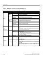
6.2.3.13
Description of the LEDs on the Control Unit 310 DP
Table 6-11
Description of the LEDs on the Control Unit
LED
Color
State
Description
-
Off
Electronics power supply outside permissible tolerance range
Steady light
The component is ready for operation and cyclic DRIVE-CLiQ
communication is taking place.
Flashing light
2 Hz
Writing to CompactFlash card
Steady light
At least one fault is present in this component.
Flashing light
0.5 Hz
CompactFlash card has not been inserted.
Boot error (e.g. firmware cannot be loaded to the RAM).
Green
Red
Flashing light
0.5 Hz
Control Unit 310 DP is ready for operation.
No software licenses for device.
Orange
Steady light
DRIVE-CLiQ communication is being established.
Flashing light
0.5 Hz
Unable to load firmware to RAM
Flashing light
2 Hz
Firmware CRC error
Off
Cyclic communication is not (yet) running.
Note:
The PROFIBUS is ready for communication when the Control Unit is
ready for operation (see RDY LED).
Steady light
Cyclic communication is running.
Flashing light
0.5 Hz
Cyclic communication is not yet running fully.
Possible reasons:
• The master is not transmitting setpoints.
• No global control (GC) or master sign-of-life is transmitted during
isochronous operation.
Green
RDY
(READY)
Red
COM
(PROFIBUS
cyclic operation) Green
OUT > 5V
MOD
6-16
Red
Steady light
Cyclic communication has been interrupted.
-
Off
Electronics power supply is missing or outside permissible tolerance
range.
Power supply ≤5 V.
Electronics power supply for measuring system available.
Power supply >5 V.
Orange
Steady light
--
Off
Notice
You must ensure that the connected encoder can be operated with a
24 V supply.
If an encoder that is designed for a 5 V supply is operated with a 24 V
supply, this can destroy the encoder electronics.
Reserved
Equipment Manual AC Drive
Manual, (GH6), 03/2006 Edition, 6SL3097-2AL00-0BP0
Control Units
6.2 Control Unit CU310 DP (PROFIBUS)
Cause and rectification of faults
The following reference contains information about the cause and rectification of faults:
Reference: /IH1/ SINAMICS S120 Commissioning Manual.
RESET button
The RESET button is located behind the blanking plate.
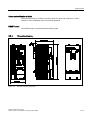
6.2.4
Dimension drawing
Figure 6-6
Dimension drawing CU310 DP
Equipment Manual AC Drive
Manual, (GH6), 03/2006 Edition, 6SL3097-2AL00-0BP0
6-17
Control Units
6.2 Control Unit CU310 DP (PROFIBUS)
6.2.5
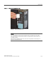
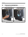
Mounting the CU310 on the Power Module Blocksize
As soon as the Power Module has been been correctly installed, the Control Unit can be
attached to the Power Module.
Snap the CU310 onto the Power Module 340
Power Module 340 (frame size D) with CU310
(frame size D)
The procedure when mounting the Control Unit on the Power Module is independent of the
frame size of the Power Modules.
6-18
Equipment Manual AC Drive
Manual, (GH6), 03/2006 Edition, 6SL3097-2AL00-0BP0
Control Units
6.2 Control Unit CU310 DP (PROFIBUS)
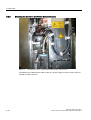
Removing the Control Unit
Removing the CU310 from the Power Module 340 (frame size D)
In order to remove the Control Unit from the Power Module, the blue release lever, as shown
in the diagram, must be pressed downwards and the Control Unit swung-out to the front.
Equipment Manual AC Drive
Manual, (GH6), 03/2006 Edition, 6SL3097-2AL00-0BP0
6-19
Control Units
6.2 Control Unit CU310 DP (PROFIBUS)
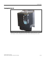
6.2.6
Mounting the CU310 in the Power Module Chassis
Figure 6-7
Mounting the CU310 in the Power Module Chassis, frame size FX
The DRIVE-CLiQ cable and the cable for the 24 V power supply must be correctly routed so
that the front flap can close.
6-20
Equipment Manual AC Drive
Manual, (GH6), 03/2006 Edition, 6SL3097-2AL00-0BP0
Control Units
6.2 Control Unit CU310 DP (PROFIBUS)
6.2.7
Technical data
Table 6-12
Technical data CU310 DP
Unit
Value
Voltage
Current (without DRIVE-CLiQ and digital outputs)
Power loss
VDC
ADC
W
DC 24 (20.4 – 28.8)
0.8
<20
PE/ground connection
At the housing with M4/3 Nm screw
Response time
The response time of digital inputs/outputs depends on the
evaluation (refer to the function diagram).
Electronics power supply
Reference: /LH1/ SINAMICS S List Manual, Chapter "Function
diagrams".
Weight
Equipment Manual AC Drive
Manual, (GH6), 03/2006 Edition, 6SL3097-2AL00-0BP0
kg
0.95
6-21
Diagnosis
Diagnostics using LEDs
8.1.3
LEDs after the Control Unit CU310 has booted
Table 8-3
Control Unit 310 – description of the LEDs after booting
LED
Color
–
G
Green
State
Description, cause
Remedy
Off
Electronics power supply is missing or outside
permissible tolerance range.
–
Steady
light
The module is ready for operation and cyclic
DRIVE–CLiQ communication is taking place.
–
Writing to CompactFlash card.
–
At least one fault is present in this module.
Remedy and
acknowledge
fault
Flashing
2 Hz
Steady
light
Check whether
CompactFlash
card is plugged
in correctly
Red
Flashing
0.5 Hz
Boot error
Replace
CompactFlash
card
Replace
Control Unit
Carry-out a
POWER ON
RDY
Green/
Flashing
Control Unit 310 is ready.
Red
0.5 Hz
No software licenses.
Steady
light
DRIVE-CLiQ communication is being
established.
(READY)
Obtain licenses
–
Check whether
CompactFlash
card is plugged
in correctly
Flashing
0.5 Hz
Unable to load firmware to RAM.
Replace
CompactFlash
card
Replace
Control Unit
Carry-out a
POWER ON
Orange
Check whether
CompactFlash
card is plugged
in correctly
Flashing
2 Hz
Firmware CRC error.
Replace
CompactFlash
card
Replace
Control Unit
Carry-out a
POWER ON
© Siemens AG, 2006. All rights reserved
SINAMICS S120 Commissioning Manual, 04/2006 Edition
8-301
Diagnosis
Diagnostics using LEDs
Table 8-3
LED
Control Unit 310 – description of the LEDs after booting, continued
Color
State
Description, cause
Remedy
Cyclic communication has not (yet) taken place.
–
Off
Note:
–
PROFIdrive is ready for communication when the
Control Unit is ready (see LED RDY).
Steady
light
COM
PROFIdrive
cyclic
operation
Green
Cyclic communication is taking place.
–
Full cyclic communication is not yet taking place.
Possible causes:
Flashing
0.5 Hz
The controller is not transmitting setpoints.
During isochronous operation, no global
–
control (GC) or a faulty global control (GC) is
transferred by the Controller.
Red
–
Steady
light
Off
Cyclic communication has been interrupted.
Remedy fault
Electronics power supply is missing or outside
permissible tolerance range.
–
Power supply 5 V
Electronics power supply for measuring system
available.
Power supply >5 V.
OUT >5 V
MOD
8-302
Steady
light
Notice
Orange
–
Off
Reserved
You must ensure that the connected encoder can
be operated with a 24 V supply. If an encoder
that is designed for a 5 V supply is operated with
a 24 V supply, this can destroy the encoder
electronics.
–
–
© Siemens AG, 2006. All rights reserved
SINAMICS S120 Commissioning Manual, 04/2006 Edition
Commissioning
Commissioning for the first time using as an example Vector AC DRIVE with BOP20
3.8.3
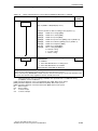
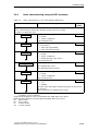
Quick commissioning using the BOP (example)
Table 3-11
Quick commissioning for a motor without a DRIVE-CLiQ interface
Description
Outlet
Factory
setting
Note:
Before commissioning for the first time, the drive must be in the factory setting.
Procedure, see Subsection 3.3.1
p0009 = 1
Device commissioning parameter filter *
0 Ready
1
1 Device configuration
30 Parameter reset
p0097 = 2
Select drive object type *
0 No selection
0
1 Drive object type SERVO
2 Drive object type VECTOR
p0009 = 0
Device commissioning parameter filter *
0 Ready
1
1 Device configuration
30 Parameter reset
DO = 2
Select drive object (DO) 2 ( = VECTOR)
1 CU
1
2 VECTOR
To select a drive object (DO), simultaneously press the Fn key and
an arrow key.
The selected project is displayed at the top left.
p0010 = 1
Drive, commissioning parameter filter *
0 Ready
1
1 Quick commissioning
30 Parameter reset
*
These parameters offer more setting possibilities than specified here. For additional setting
possibilities, see the List Manual
[CDS] Parameter depends on the Command Data Sets (CDS). Data set 0 is preset.
[DDS] Parameter depends on the Drive Data Sets (DDS). Data set 0 is preset.
[MDS] Parameter depends on the Motor Data Sets (MDS). Data set 0 is preset.
BI
Binector Input
BO
Bector Output
CI
Connector Input
CO
Connector Output
© Siemens AG, 2006. All rights reserved
SINAMICS S120 Commissioning Manual, 04/2006 Edition
3-101
Commissioning
Commissioning for the first time using as an example Vector AC DRIVE with BOP20
Table 3-11
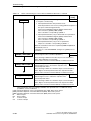
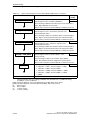
Quick commissioning for a motor without a DRIVE-CLiQ interface, continued
Outlet
p0100 = …
Description
Factory
setting
IEC/NEMA mot stds
0
0 IEC motor (SI units, e.g. kW)
Pre-assignment:
Rated motor frequency (p0310): 50 Hz
Enter the power factor cos ϕ (p0308)
1 NEMA motor (US units, e.g. hp)
Pre-assignment:
Rated motor frequency (p0310): 60 Hz
Enter the efficiency (p0309)
Note
If p0100 is changed, all of the rated motor parameters are reset.
p0300[0] = 15
Motor type selection [MDS]*
0
0 No motor selected
Commissioning cannot be exited.
Standard motors:
1 Induction motor (rotating)
2 Synchronous motor (rotating, permanent-magnet)
5 Synchronous motor (rotary, separately-excited)
1x 1LAx standard induction motor (x = 1, 5, 6, 7, 8)
12 1LE2 standard induction motor (NEMA)
You must individually enter rated motor data (see type plate) in
parameter p0304 and onwards.
SIEMENS catalog motors:
10x 1PHx induction motor (x = 2, 4, 7)
13x 1PMx induction motor (x = 4, 6)
2xx Synchronous motors
The list motors are contained in a motor code list (see
Attachment A). The motors are selected by entering the motor
type (p0300) and the motor code number (p0301). The
parameter for the rated motor data (p0304 and onwards) are
appropriately pre-assigned.
*
These parameters offer more setting possibilities than specified here. For additional setting
possibilities, see the List Manual
[CDS] Parameter depends on the Command Data Sets (CDS). Data set 0 is preset.
[DDS] Parameter depends on the Drive Data Sets (DDS). Data set 0 is preset.
[MDS] Parameter depends on the Motor Data Sets (MDS). Data set 0 is preset.
BI
Binector Input
BO
Bector Output
CI
Connector Input
CO
Connector Output
3-102
© Siemens AG, 2006. All rights reserved
SINAMICS S120 Commissioning Manual, 04/2006 Edition
Commissioning
Commissioning for the first time using as an example Vector AC DRIVE with BOP20
Table 3-11
Quick commissioning for a motor without a DRIVE-CLiQ interface, continued
Outlet
p0304[0] = …
…
Description
Factory
setting
Rated motor data [MDS]
–
Only for p0300 < 100 (third-party motor)
Enter the rated motor data according to the type plate, e.g.
p0304[0
p1900 = 1
Rated motor voltage [MDS]
p0305[0]
Rated motor current [MDS]
p0307[0]
Rated motor power [MDS]
p0308[0]
Rated motor power factor [MDS] (only for p0100 = 0)
p0309[0]
Rated motor efficiency [MDS] (only for p0100 = 1)
p0310[0]
Rated motor frequency [MDS]
p0311[0]
Rated motor speed [MDS]
p0335[0]
Motor cooling type [MDS] *
0: Natural cooling
1: Forced cooling
2 Water cooling
Motor data identification and rotating
measurement*
0 Inhibited
2
1 Motor data identification for rotating motor
2 Motor data identification at standstill
Alarms A07991 and A7980 are displayed
Danger
During the motor identification routine, the drive can cause the motor to move.
When commissioning, EMERGENCY STOP functions must be functioning. To protect the machines and
personnel, the relevant safety regulations must be carefully observed.
*
These parameters offer more setting possibilities than specified here. For additional setting
possibilities, see the List Manual
[CDS] Parameter depends on the Command Data Sets (CDS). Data set 0 is preset.
[DDS] Parameter depends on the Drive Data Sets (DDS). Data set 0 is preset.
[MDS] Parameter depends on the Motor Data Sets (MDS). Data set 0 is preset.
BI
Binector Input
BO
Bector Output
CI
Connector Input
CO
Connector Output
© Siemens AG, 2006. All rights reserved
SINAMICS S120 Commissioning Manual, 04/2006 Edition
3-103
Commissioning
Commissioning for the first time using as an example Vector AC DRIVE with BOP20
Table 3-11
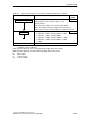
Quick commissioning for a motor without a DRIVE-CLiQ interface, continued
Outlet
p3900 = 3
Description
Factory
setting
Completion of quick commissioning *
0 No quick commissioning
0
1 Quick parameterization after parameter reset:
Reset all parameters to the factory setting (with the exception of
the quick commissioning parameter)
Restore the PROFIBUS telegram (p0922) and the BICO
interconnections (p0700, p1000, p1500)
Motor calculation corresponding to p0340 = 1
2 Quick parameterization (only) for BICO and motor parameters
Restore the PROFIBUS telegram (p0922) and the BICO
interconnections (p0700, p1000, p1500)
Motor calculation corresponding to p0340 = 1
3 Quick parameterization (only) for motor parameters
Only motor calculation corresponding to p0340 = 1
When the calculations have been completed, p3900 and p0010 are
automatically set to 0.
Parameters of a selected SIEMENS catalog motor (p0301) are not
overwritten.
p0840[0] = r0019
r0019.0(DO
0(DO 1)
BI: ON/OFF1 [CDS]
Sets the signal source for STW1.0 (ON/OFF1)
0
Interconnecting to r0019.0 of the drive object Control Unit (DO 1)
Effect: Signal ON/OFF1 from the BOP
Binector interconnections with the BOP20, see Subsection 9.13.2
p1035[0] = r0019
r0019.13
13 (DO 1)
BI: Motorized potentiometer, raise setpoint [CDS]
Sets the signal source to increase the setpoint for the
motorized potentiometer
0
Interconnecting to r0019.13 of the drive object Control Unit (DO 1)
Effect: Signal, motorized potentiometer raise setpoint from BOP
Binector interconnections with the BOP20, see Subsection 9.13.2
p1036[0] = r0019
r0019.14
14 (DO 1)
BI: Motorized potentiometer, lower setpoint [CDS]
Sets the signal source to reduce the setpoint for the
motorized potentiometer
0
Interconnecting to r0019.14 of the drive object Control Unit (DO 1)
Effect: Signal, motorized potentiometer lower setpoint from BOP
Binector interconnections with the BOP20, see Subsection 9.13.2
*
These parameters offer more setting possibilities than specified here. For additional setting
possibilities, see the List Manual
[CDS] Parameter depends on the Command Data Sets (CDS). Data set 0 is preset.
[DDS] Parameter depends on the Drive Data Sets (DDS). Data set 0 is preset.
[MDS] Parameter depends on the Motor Data Sets (MDS). Data set 0 is preset.
BI
Binector Input
BO
Bector Output
CI
Connector Input
CO
Connector Output
3-104
© Siemens AG, 2006. All rights reserved
SINAMICS S120 Commissioning Manual, 04/2006 Edition
Commissioning
Commissioning for the first time using as an example Vector AC DRIVE with BOP20
Table 3-11
Quick commissioning for a motor without a DRIVE-CLiQ interface, continued
Outlet
p1070[0] = r1050 (DO 63)
Description
Factory
setting
CI: Main setpoint [CDS]
Sets the signal source for speed setpoint 1 of the
speed controller
0
Interconnecting to r1050 on its own drive object (DO 63)
Effect: Motorized potentiometer supplies the speed setpoint
Binector interconnections with the BOP20, see Subsection 9.13.2
p0006 = 0
BOP operating display mode*
0 Operation –> r0021, otherwise r0020 <–> r0021
4
1 Operation –> r0021, otherwise r0020
2 Operation –> p0005, otherwise p0005 <–> r0020
3 Operation –> r0002, otherwise r0002 <–> r0020
4 p0005
Save all parameters
Press the P key for 3s
*
These parameters offer more setting possibilities than specified here. For additional setting
possibilities, see the List Manual
[CDS] Parameter depends on the Command Data Sets (CDS). Data set 0 is preset.
[DDS] Parameter depends on the Drive Data Sets (DDS). Data set 0 is preset.
[MDS] Parameter depends on the Motor Data Sets (MDS). Data set 0 is preset.
BI
Binector Input
BO
Bector Output
CI
Connector Input
CO
Connector Output
© Siemens AG, 2006. All rights reserved
SINAMICS S120 Commissioning Manual, 04/2006 Edition
3-105
Commissioning
Commissioning for the first time using as an example Servo AC DRIVE with BOP20
3.9
Commissioning for the first time using as an example
Servo AC DRIVE with BOP20
The commissioning example described in this chapter shows all the necessary
configuration and parameter settings. Commissioning is performed using the
BOP20.
Requirements for commissioning
1. The commissioning requirements have been met.
––> see Section 2.1
2. The checklist for commissioning has been completed and all items are O.K.
––> see Section 2.1
3-106
© Siemens AG, 2006. All rights reserved
SINAMICS S120 Commissioning Manual, 04/2006 Edition
Commissioning
Commissioning for the first time using as an example Servo AC DRIVE with BOP20
3.9.1
Task
1. Commission a drive unit (operating mode servo, closed-loop speed control) with
the following components:
Table 3-12
Component overview
Component
Designation
Order No.
Closed-loop control
Control Unit
Control Unit 310 DP
6SL3040-0LA00-0AAx
Operator Panel
Basic Operator Panel 20 (BOP20)
6SL3055-0AA00-4BAx
Power Module
Power Module 340
6SL3210-xxxx-xxxx
Motor
Synchronous motor
with DRIVE-CLiQ interface
1FK7061-7AF7x-xAxx
Motor encoder via
DRIVE-CLiQ
Incremental encoder sin/cos C/D
1Vpp 2048 p/r
1FK7xxx-xxxxx-xAxx
Infeed and drive
2. Commissioning is performed using the BOP20.
3. The function keys of the Basic Operator Panel (BOP) should be parameterized
so that the ON/OFF signal and the speed setpoints are entered using these
keys.
© Siemens AG, 2006. All rights reserved
SINAMICS S120 Commissioning Manual, 04/2006 Edition
3-107
Commissioning
Commissioning for the first time using as an example Servo AC DRIVE with BOP20
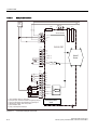
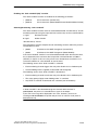
3.9.2
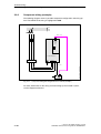
Component wiring (example)
The following diagram shows a possible component configuration and wiring option. The DRIVE-CLiQ wiring is highlighted in bold.
L1
L2
L3
DRIVE –CLiQ
X100
Control
Unit
310
X124
Power Module 340
Line reactor
Line filter
4
Fig. 3-14
ibn_ac_drive_smi_verdrahtung.vsd
Motor line
Component wiring with integrated sensor module (example)
For more information on the wiring and connecting-up the encoder system,
see the Equipment Manual.
3-108
© Siemens AG, 2006. All rights reserved
SINAMICS S120 Commissioning Manual, 04/2006 Edition
Commissioning
Commissioning for the first time using as an example Servo AC DRIVE with BOP20
3.9.3
Quick commissioning using the BOP (example)
Table 3-13
Quick commissioning for a motor with a DRIVE-CLiQ interface
Description
Outlet
Factory
setting
Note:
Before commissioning for the first time, the drive must be in the factory setting.
Procedure, see Subsection 3.3.1
p0009 = 1
Device commissioning parameter filter *
0 Ready
1
1 Device configuration
30 Parameter reset
p0097 = 1
Select drive object type *
0 No selection
0
1 Drive object type SERVO
2 Drive object type VECTOR
p0009 = 2
Device commissioning parameter filter *
0 Ready
1
1 Device configuration
2 Define drive type / drive options
30 Parameter reset
p0108[1]
p
[ ] = H0104
Drive object, function module *
0000
Bit 2 Speed/torque control
Bit 8 Expanded setpoint channel
p0009 = 0
Device commissioning parameter filter *
0 Ready
1
1 Device configuration
30 Parameter reset
DO = 2
Select drive object (DO) 2 ( = SERVO)
1 CU
1
2 SERVO
To select a drive object (DO), simultaneously press the Fn key and
an arrow key.
The selected project is displayed at the top left.
*
These parameters offer more setting possibilities than specified here. For additional setting
possibilities, see the List Manual
[CDS] Parameter depends on the Command Data Sets (CDS). Data set 0 is preset.
[DDS] Parameter depends on the Drive Data Sets (DDS). Data set 0 is preset.
BI
Binector Input
BO
Bector Output
CI
Connector Input
CO
Connector Output
© Siemens AG, 2006. All rights reserved
SINAMICS S120 Commissioning Manual, 04/2006 Edition
3-109
Commissioning
Commissioning for the first time using as an example Servo AC DRIVE with BOP20
Table 3-13
Quick commissioning for a motor with a DRIVE-CLiQ interface, continued
Outlet
p0840[0] = r0019
r0019.0(DO
0(DO 1)
Description
Factory
setting
BI: ON/OFF1 [CDS]
Sets the signal source for STW1.0 (ON/OFF1)
0
Interconnecting to r0019.0 of the drive object Control Unit (DO 1)
Effect: Signal ON/OFF1 from the BOP
Binector interconnections with the BOP20, see Subsection 9.13.2
p1035[0] = r0019
r0019.13
13 (DO 1)
BI: Motorized potentiometer, raise setpoint [CDS]
Sets the signal source to increase the setpoint for the
motorized potentiometer
0
Interconnecting to r0019.13 of the drive object Control Unit (DO 1)
Effect: Signal, motorized potentiometer raise setpoint from BOP
Binector interconnections with the BOP20, see Subsection 9.13.2
p1036[0] = r0019
r0019.14
14 (DO 1)
BI: Motorized potentiometer, lower setpoint [CDS]
Sets the signal source to reduce the setpoint for the
motorized potentiometer
0
Interconnecting to r0019.14 of the drive object Control Unit (DO 1)
Effect: Signal, motorized potentiometer lower setpoint from BOP
Binector interconnections with the BOP20, see Subsection 9.13.2
p1070[0] = r1050 (DO 63)
CI: Main setpoint [CDS]
Sets the signal source for speed setpoint 1 of the
speed controller
0
Interconnecting to r1050 on its own drive object (DO 63)
Effect: Motorized potentiometer supplies the speed setpoint
Binector interconnections with the BOP20, see Subsection 9.13.2
p0006 = 0
BOP operating display mode*
0 Operation –> r0021, otherwise r0020 <–> r0021
4
1 Operation –> r0021, otherwise r0020
2 Operation –> p0005, otherwise p0005 <–> r0020
3 Operation –> r0002, otherwise r0002 <–> r0020
4 p0005
Save all parameters
Press the P key for 3s
*
These parameters offer more setting possibilities than specified here. For additional setting
possibilities, see the List Manual
[CDS] Parameter depends on the Command Data Sets (CDS). Data set 0 is preset.
[DDS] Parameter depends on the Drive Data Sets (DDS). Data set 0 is preset.
BI
Binector Input
BO
Bector Output
CI
Connector Input
CO
Connector Output
3-110
© Siemens AG, 2006. All rights reserved
SINAMICS S120 Commissioning Manual, 04/2006 Edition
Commissioning
Commissioning linear motors (servo)
3.10
Commissioning linear motors (servo)
3.10.1
General information on commissioning linear motors
Before commissioning motors, the following questions must be answered:
Are all of the prerequisites for commissioning checked and were the points in
the checklist for commissioning checked (refer to Chapter 2)?
Detailed information on linear motors, encoders and power connection, configuring
and mounting are provided in:
/PJLM/
Configuration Manual for Linear Motors 1FN1, 1FN3
Terminology for rotary and linear drives
Table 3-14
Comparison
Terminology for rotary drives
Terminology for linear drives
Speed
Velocity
Torque
Force
Stator
Primary section
Rotor
Secondary section
Rotor
Secondary section
Direction of rotation
Direction
Pulse number
Grid spacing
Rotate
Run
Checks in the no-current state
The following checks can be made:
1. Linear motor
– Which linear motor is being used?
1FN _ _ _ _ – _ _ _ _ _ – _ _ _ _
– Is the motor already mounted and ready to be powered up?
– If a cooling circuit is being used, is it functional?
2. Mechanical system
– Is the axis easy to move over the complete traversing range?
– Does the air gap between the primary and secondary section and the
mounting dimensions correspond to the motor manufacturer’s data?
© Siemens AG, 2006. All rights reserved
SINAMICS S120 Commissioning Manual, 04/2006 Edition
3-111
Commissioning
Commissioning linear motors (servo)
– Hanging (suspended) axis:
If wait equalizing is used for the axis is this functioning?
– Brake:
If a brake is being used, is it correctly controlled (see Function Manual)?
– Traversing range limiting:
Are the mechanical end stops available and tightly bolted to both ends of the
traversing path?
– Are the moving feeder cables correctly routed in a cable drag assembly?
3. Measuring system
– Which measuring system is being used?
____________
Absolute or incremental abs incr Grid spacing _ _ _ _ _ _ _ _ _ _ µm
Zero marks (number and position) _ _ _ _ _ _ _ _ _ _ _ _
– Where is the positive drive direction?
Where is the positive counting direction of the measuring system?
Invert (p0410)? yes no 4. Wiring
– Power Module (connect UVW, phase sequence, clockwise rotating field)
– Protective conductor connected?
– Screen connected?
– Temperature monitoring circuits:
Are the cables connected to the terminal block of the screen connecting
plate?
––> Temperature sensor (Temp-F):
The temperature sensor (Temp-F) can be used to measure the mean
absolute winding temperature.
––> Overtemperature switch (Temp-S)
The over temperature shutdown circuit (Temp-S) allows each
individual motor phase winding to be digitally monitored for an
overtemperature condition.
3-112
© Siemens AG, 2006. All rights reserved
SINAMICS S120 Commissioning Manual, 04/2006 Edition
SINAMICS Safety Integrated
Safe standstill (SH)
7.2
Safe standstill (SH)
General description
In conjunction with a machine function or in the event of an error, the “Safe standstill (SH)” function is used to safely disconnect the torque-generating motor power
supply.
When the function is selected, the drive unit is in a “safe status”. The power-on
disable function prevents the drive unit from being restarted.
The pulse cancellation integrated in the Motor Modules / Power Modules is a basis
for this function.
Features of “safe standstill”
This function is integrated in the drive; this means that a higher-level controller
is not required.
The function is drive specific, that is, it must be commissioned individually on a
drive-by-drive basis.
Enable of the function using parameters required
The terminals for the “safe standstill” function can be grouped together.
Not for the Control Unit CU310.
When the “safe standstill” function is selected:
– The motor cannot be started accidentally.
– The pulse disable safely disconnects the torque-generating motor power
supply.
– The power unit and motor are not electrically isolated.
!
Caution
Appropriate measures must be taken to ensure that the motor does not move
once the motor power supply has been disconnected (“coast down”) (e.g. enable
the “Safe brake control” function with a vertical axis).
© Siemens AG, 2006. All rights reserved
SINAMICS S120 Commissioning Manual, 04/2006 Edition
7-255
SINAMICS Safety Integrated
Safe standstill (SH)
!
Caution
If two power transistors in the power unit (one in the upper and one in the lower
bridge) fail at the same time, this can cause a momentary movement.
The maximum movement can be:
Synchronous rotary motors: max. movement = 180 / number of pole pairs
Synchronous linear motors: max. movement = pole width
The status of the “Safe standstill” function is displayed via the appropriate
parameters.
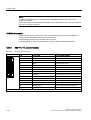
Overview of the safety function terminals for SINAMICS S120
The different power unit formats of SINAMICS S120 have different terminal designations for the inputs of the safety functions. These are shown in the following
table.
Table 7-1
Inputs for safety functions
1. Shutdown path (p9620)
Control unit CU320
X122.1....4 / X132.1...4
(on the CU320)
2. Shutdown path
(see Motor Modules /
Power Modules)
Digital inputs 0 to 7
Single Motor Module
Booksize
(see CU320)
X21.3 and X21.4
(on the Motor Module)
Single Motor Module
Chassis
(see CU320)
X41.1 and X41.2
(on the CIB)
Double Motor Module
(see CU320)
X21.3 and X21.4
(motor connection X1)/
X22.3 and X22.4
(motor connection X2)
(on the Motor Module)
Power Module Blocksize
with CUA31
(see CU320)
X210.3 and X210.4
(on the CUA31)
Power Module Blocksize
with CU310
X121.1...4 (on the CU310)
X120.7 and X120.8
(on the CU310)
Power Module Chassis with
CU310
X121.1...4 (on the CU310)
Booksize
Digital inputs 0 to 3
Digital inputs 0 to 3
X41.1 and X41.2
(on the CIB)
For further information about the terminals, refer to the Equipment Manuals
7-256
© Siemens AG, 2006. All rights reserved
SINAMICS S120 Commissioning Manual, 04/2006 Edition
SINAMICS Safety Integrated
Safe standstill (SH)
Enabling the “Safe standstill (SH)” function
The “Safe standstill” function is enabled via the following parameters:
p9601.0
SH via terminals (Control Unit)
p9801.0
SH via terminals (Motor Module/Power Module/CUA31/CU310)
Selecting/deselecting “Safe standstill”
The “Safe standstill” function must be selected/deselected “simultaneously” in both
monitoring channels using the input terminals and act only on the associated drive.
1 signal:
Deselect function
0 signal:
Select function
“Simultaneously” means:
The changeover must be complete in both monitoring channels within the parameterized tolerance time.
p9650
SI tolerance time SGE changeover (Control Unit)
p9850
SI tolerance time SGE changeover (Motor Module)
If the “Safe standstill” function is not selected/deselected within the tolerance time,
this is detected by the crosswise data comparison and fault F01611 or F30611
(STOP F) is output. In this case, the pulses have already been canceled as a result of the selection of “safe standstill” on one channel.
The following occurs when “Safe standstill” is selected:
Each monitoring channel triggers the safe pulse disable via its shutdown path.
A motor holding brake is applied (if connected and configured).
The following occurs when “Safe standstill” is deselected:
Each monitoring channel cancels the safe pulse disable via its shutdown path.
The safety prompt “Apply motor holding brake” is canceled.
Any STOP F or STOP A commands are canceled (see r9772/r9872).
Note
If “Safe standstill” is de-selected through one channel within the time in
p9650/p9850, the pulses are cancelled but a signal is not output.
If you want a message to be displayed in this case, however, you have to
reconfigure N01620/N30620 via p2118 and p2119 as an alarm or fault (refer to
Subsection 8.3.3).
© Siemens AG, 2006. All rights reserved
SINAMICS S120 Commissioning Manual, 04/2006 Edition
7-259
Diagnosis
Diagnostics using STARTER
8.2.4
Measuring sockets
Description
The measuring sockets are used to output analog signals. Any interconnectable
signal can be output to any measuring socket on the Control Unit.
Caution
The measuring sockets should be used for commissioning and servicing purposes
only.
The measurements may only be carried out by properly trained specialist
personnel.
Measuring sockets j 2 mm
T0
Meas. socket 0
T1
Meas. socket 1
T2
Meas. socket 2
Measuring signal
M
Reference
(with default scale
setting)
4.98 V
2.49 V
0 % of
measuring signal
0V
Fig. 8-9
Arrangement of the measuring sockets on the Control Unit CU310/CU320
© Siemens AG, 2006. All rights reserved
SINAMICS S120 Commissioning Manual, 04/2006 Edition
8-325
Basic Information about the Drive System
Inputs/outputs
9.9
Inputs/outputs
9.9.1
Overview of inputs/outputs
The following digital/analog inputs/outputs are available:
Table 9-20
Overview of inputs/outputs
Digital
Analog
Component
Inputs
Inputs/
outputs
bidirectional
Outputs
Inputs
Outputs
CU310
41)
43)
–
–
–
CU320
81)
82)
–
–
–
TB30
4
–
4
2
2
TM15
–
24
–
–
–
8
4
–
2
2
–
1
–
TM31
Relay outputs:
2
Temperature sensor input:
1
TM41
4
4
Incremental encoder emulation: 1 (also refer to: Function Manual)
1) Adjustable: floating or non-floating
2) 6 of these are “high-speed inputs”
3) 3 of these are “high-speed inputs”
Note
For detailed information about the hardware properties of I/Os, please refer to:
References:
/GH1/ SINAMICS S120 Equipment Manual: Control Units
For detailed information about the structural relationships between all I/Os of a
component and their parameters, please refer to the function diagrams in:
References:
9-380
/LH1/
SINAMICS S List Manual
© Siemens AG, 2006. All rights reserved
SINAMICS S120 Commissioning Manual, 04/2006 Edition
Basic Information about the Drive System
Licensing
9.12
Licensing
Description
To use the SINAMICS S120 drive system and the activated options, you need to
assign the corresponding licenses to the hardware. When doing so, you receive a
license key, which electronically links the relevant option with the hardware.
The license key is an electronic license stamp that indicates that one or more software licenses are owned.
Actual customer verification of the license for the software that is subject to license
is called a certificate of license.
Note
Refer to the order documentation (e.g. catalogs) for information on basic functions
and functions subject to license.
An insufficient license is indicated via the following alarm and LED on the Control
Unit:
A13000
License not sufficient
READY LED
Flashes green/red at 0.5 Hz
Notice
The drive can only be operated with an insufficient license during commissioning
and servicing.
The drive requires a sufficient license in order for it to operate normally.
Information regarding the Performance 1 option (this is not valid for Control Unit CU310)
The option Performance 1 (Order No.: 6SL3074-0AA01-0AA0) is required from a
computation time utilization greater than 50 %. The remaining computation time is
displayed in parameter r9976[2]. As of a CPU runtime utilization greater than 50%,
alarm A13000 is output and the READY LED on the Control Unit flashes green/red
at 0.5 Hz.
Properties of the license key
Assigned to a specific CompactFlash card.
Is stored on the non-volatile CompactFlash card.
Is not transferrable.
Can be acquired using the “WEB License Manager” from a license database.
© Siemens AG, 2006. All rights reserved
SINAMICS S120 Commissioning Manual, 04/2006 Edition
9-397
p0005 BOP operating display selection
Page 1 of 1
p0005 BOP operating display selection
Changeable: U T
Quick commission: NO
Access level: 2
Data type: Unsigned16
Data block: -
Function diagram: -
P group: Object: A_INF, A_INFMV, B_INF,
B_INFMV, CU_G, CU_GL, CU_GM, CU_S,
DMC20, SERVO, S_INF, TB30, TM15,
TM15DI_DO, TM17, TM31, TM41, VECTOR,
VECTORMV
Version: 2402300
Group of units: -
Unit selection: -
Min
Max
Factory setting
0
65535
[0] 2
Description:
Sets the parameter number for display for p0006 = 2, 4 for the Basic Operator Panel (BOP).
Examples for the SERVO drive object:
p0005 = 21: Speed actual value smoothed (r0021)
p0005 = 25: Drive output voltage smoothed (r0025)
p0005 = 26: Speed actual value smoothed (r0026)
p0005 = 27: Absolute current actual value, smoothed (r0027)
Dependence:
See also: p0006
Note:
Only the monitoring parameters (only read parameters) can be set, that actually exist for the actual drive
object.
mk:@MSITStore:C:\Siemens\Step7\u7umc\help\drive\vector_svc\02_40\u7idpxhbb58b.ch...
2/7/2007
p0006 BOP operating display mode
Page 1 of 1
p0006 BOP operating display mode
Changeable: U T
Quick commission: NO
Access level: 3
Data type: Integer16
Data block: -
Function diagram: -
Object: A_INF, A_INFMV, B_INF, SERVO,
S_INF, VECTOR, VECTORMV
P group: -
Version: 2402300
Group of units: -
Unit selection: -
Min
Max
Factory setting
0
4
[0] 4
Description:
Sets the mode of the operating display for the Basic Operator Panel (BOP) in the operating states "ready" and
"operation".
Values:
0: Operation
1: Operation
2: Operation
3: Operation
4: p0005
-->
-->
-->
-->
r0021, otherwise r0020 <--> r0021
r0021, otherwise r0020
p0005, otherwise p0005 <--> r0020
r0002, otherwise r0002 <--> r0020
Dependence:
See also: p0005
Note:
Mode 0 ... 3 can only be selected if also r0020, r0021 are available on the drive object.
Mode 4 is available for all drive objects.
mk:@MSITStore:C:\Siemens\Step7\u7umc\help\drive\vector_svc\02_40\u7idpxhbb58b.ch...
2/7/2007
p0013[0...49] BOP user-defined list
Page 1 of 1
p0013[0...49] BOP user-defined list
Changeable: U T
Quick commission: NO
Access level: 3
Data type: Unsigned16
Data block: -
Function diagram: -
P group: Functions
Object: A_INF, A_INFMV, B_INF,
B_INFMV, CU_G, CU_GL, CU_GM, CU_S,
DMC20, SERVO, S_INF, TB30, TM15,
TM15DI_DO, TM17, TM31, TM41, VECTOR,
VECTORMV
Version: 2402300
Group of units: -
Unit selection: -
Min
Max
Factory setting
0
65535
[0] 0
Description:
Sets the required parameters to read and write via the Basic Operator Panel (BOP).
Activation:
1. p0003 = 3 (expert).
2. p0013[0...49] = requested parameter number
3. If required, enter p0011 = password in order to prevent non-authorized de-activation.
4. p0003 = 0 --> activates the selected user-defined list.
De-activation/change:
1. p0003 = 3 (expert).
2. If required, p0012 = p0011, in order to be authorized to change or de-activate the list.
3. If required p0013[0...49] = required parameter number.
4. p0003 = 0 --> activates the modified user-defined list.
5. p0003 > 0 --> de-activates the user-defined list.
Dependence:
See also: p0009, p0011, p0012, p0976
Note:
The following parameters can be read and written on the Control Unit drive object:
- p0003 (access stage)
- p0009 (device commissioning, parameter filter)
- p0012 (BOP password acknowledgment (p0013))
The following applies for the user-defined list:
- password protection is only available on the drive object Control Unit and is valid for all of the drive
objects.
- p0013 cannot be included in the user-defined list for all drive objects.
- p0003, p0009, p0011, p0012, p0976 cannot, for the drive object Control Unit, be included in the userdefined list.
- the user-defined list can be cleared and de-activated "restore factory setting".
A value of 0 means: Entry is empty.
mk:@MSITStore:C:\Siemens\Step7\u7umc\help\drive\vector_svc\02_40\u7idpxhbb58b.ch...
2/7/2007
Additional system components
3.1
3.1.1
3.1
3
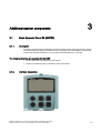
Basic Operator Panel 20 (BOP20)
Description
The Basic Operator Panel 20 (BOP20) is a basic operator panel with six keys and a display
unit with background lighting. The BOP20 can be plugged onto the SINAMICS Control Unit
CU320 and operated. Operation is only possible from SINAMICS V2.4 onwards.
The following functions are possible with the BOP:
• Input of parameters and activation of functions
• Display of operating modes, parameters, alarms and faults
3.1.2
Interface description
Figure 3-1
Basic Operator Panel (BOP20)
Equipment Manual for Control Units and Additional System Components
Equipment Manual, (GH1), 03/2006 Edition, 6SL3097-2AH00-0BP3
3-1
Additional system components
3.1 Basic Operator Panel 20 (BOP20)
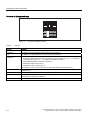
Overview of displays and keys
Figure 3-2
Table 3-1
Overview of displays and keys
Displays
Display
Meaning
top left
2 positions
The active drive object of the BOP is displayed here.
The displays and key operations always refer to this drive object.
RUN
Is lit (bright) if the displayed drive is in the RUN state (in operation).
top right
2 positions
The following is displayed in this field:
• More than 6 digits: Characters that are present but cannot be seen (e.g. “r2” ––> 2 characters
to the right are invisible, “L1” ––> 1 character to the left is invisible)
• Faults: Selects/displays other drives with faults
• Designation of BICO inputs (bi, ci)
• Designation of BICO outputs (bo, co)
Source object of a BICO interconnection to a drive object different than the active one.
S
Is (bright) if at least one parameter was changed and the value was not transferred into the nonvolatile memory.
P
Is lit (bright) if, for a parameter, the value only becomes effective after pressing the P key.
C
Is light (bright) if at least one parameter was changed and the calculation for consistent data
management has still not been initiated.
Below, 6 position
Displays, e.g. parameters, indices, faults and alarms.
3-2
Equipment Manual for Control Units and Additional System Components
Equipment Manual, (GH1), 03/2006 Edition, 6SL3097-2AH00-0BP3
Additional system components
3.1 Basic Operator Panel 20 (BOP20)
BOP20 keyboard
Table 3-2
Assignment of the BOP20 keyboard
Key
Name
Meaning
ON
Powers-up the drive - the "ON/OFF1", "OFF2" or "OFF3"
commands for this purpose should come from the BOP.
OFF
Powers-down the drive - the "ON/OFF1", "OFF2" or "OFF3"
commands for this purpose should come from the BOP.
Note:
The effectiveness of these keys can be defined using the
appropriate BICO parameterization (e.g. using these keys, it is
possible to simultaneously control all of the axes that have been
configured).
The structure of the BOP control word corresponds to the structure
of the PROFIBUS control word.
Functions
The significance of these keys depends on the actual display.
Note:
The effectiveness of this key to acknowledge faults can be defined
using the appropriate BiCo parameterization.
Parameter
The significance of these keys depends on the actual display.
Raise
The keys are dependent on the actual display and are used to
raise or lower values.
Lower
Displays and operating the BOP20
Information about the displays and using the BOP20 is provided in the following reference:
Reference: /IH1/ SINAMICS S120 Commissioning Manual
Equipment Manual for Control Units and Additional System Components
Equipment Manual, (GH1), 03/2006 Edition, 6SL3097-2AH00-0BP3
3-3
Additional system components
3.1 Basic Operator Panel 20 (BOP20)
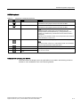
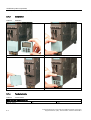
3.1.3
Installation
Table 3-3
Installation
1. CU320 and BOP20
2. Press the bars of the cover together
3. Remove the cover
4. Locate the BOP20
3.1.4
Technical data
Table 3-4
Technical data
Basic Operator Panel 20 (BOP20)
Weight, approx.
3-4
kg
0.02
Equipment Manual for Control Units and Additional System Components
Equipment Manual, (GH1), 03/2006 Edition, 6SL3097-2AH00-0BP3