1
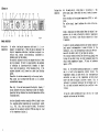
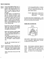
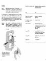
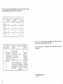
OPERATING INSTRUCTIONS
Electronically controlled Ovens
with programme controller
Models 500 - 800
tbngratulations on your choice of a MEMMERT oven!
Manufactured in West Germany using the latest production techniques and
finest materials available, you now possess a technically superior and
fully developed product. Your oven has already undergone extensive testing
in our factory and by observing the following operation and service
instructions you will be assured that the equipment will give satisfactory
service over many years.
The physical and chemical properties of your load (e. g. inflarrmation
temp, e t c ) have strictly to be observed, as otherwise considerable
damages (load, oven, surroundings of apparatus) can appear.
Technical
data summary
Temperature
range
Quality of
material
Menmert is using stainless steel (Spec. 1.4301) for the
external casing as well as for the interior, outstanding
because of its high stability, optimum hygienic features
and corrosion resistance against many (not all!) chemical
combinations (attention e.g. at chlorine combinations!)
By regular cleaning of the easy to clean interior, residues
are avoided which at continuous influence can inopair the
outfit and function of the oven.
INSTALLATION OPTIONS
Menmert ovens Series UEr BE, ULE with programme-controller
are electrically heated. The temperature in the interior is
continuously controlled by a microprocessor-controller with
pulse package control. The power module is separated from
the controller electronics by an optocoupler to ensure safe
electrical isolation according to VDE regulations (not axplosion-proof, see "Loading1').
Ovens Series UE, BE have natural air circulation. Series
ULE ovens have air circulation assisted by a fan.
The doors are opened by pulling the door handles.
Model
500
600
700
A
mm
575
015
1055
in
22,64
32,09
41,54
B
mm
920
1080
1240
in
36,22
42,52
48,82
From 5°C above ambient to nominal temperature = maximum
temperature (see rating plate). The oven operates at
ambient temperatures between 0°C and +27°C.
Overheat
Class 3.1 to DIN 12 880 fitted as standard (see table on
safety device page 14).
Electrical
supply
Single-phase or 3-phase a.c. supply 50 or 60 Hz. For
voltage rating see rating plate. Protection Class 1. Operating insulation with ground conductor to VDE 0700, Protection IP 20, no humidity protection to DIN 40 050. Interference suppression Grade N to VDE 0875.
For
Switzerland
The rrodels UE 600, ULE 600 are to be connected to 220/380 V
3N~ only.
fig. b
fig. c
Attention!
Installation
options
Optimum control and thermal conditions can only be ensured
if the unit is hung or positioned accurately horizontally
(use spirit level if necessary). If using a stand
(accessory for models 500 to 700f fig. c) or if having
model 800, then ensure that the floor is level. Ensure at
least 150 inn (series UE/ULE) resp. 80 mm (series BE) clearance between back of oven and wall. The distance between
ceiling and oven should not be less than 200 nrm. After the
cabinet has been set horizontally the door can be adjusted
if required (see Service Instructions).
Extremely strong shocks during transport can cause a displacement of the
temperature sensors in the holding clips inside the working space.
Take care before the first putting into operation that the temperature
sensors are checked on their correct position and if necessary slided
cautiously into the holding clip resp. pulled out of the holding clip (see
drawing).
Model 800 is movable. The front castors are lockable by
means of a fixation. In order to grant the stability the
front castors must always be adjusted to the front for
locking.
Wall mounting Up to model 700 for all ovens metal mounting brackets (see
(except
fig. a) are available. Mounting bracket is delivered with
model 800)
incombustible plate. Dimensions of fixing screws and dowels
depend on the weight of the charge and the quality of the
wall.
Stacking
version
(not with
model 800)
ceiling of
working space
Where the requirement is for two ovens of the same size to
be placed one on top of the other, the oven with the least
working temperature should be placed at the bottom
(fig. b ) .
Remove the front feet of the top oven and replace them with
the ones supplied with the stacking device (only if the
ovens are not originally supplied with the stacking device.) Remove the top of the bottom oven and turning it
upside down place the drilling jig into the back corner.
Mark out the hole position and drill a 4,2 mm diameter
hole. With the screws provided fix the centering cylinders
into position and re-fix top cover.
Model 700 can only be stacked with an intermediate frame.
Warning!
Before retroving top cover - pull out plug!
Attention! Take special care when working at high temperature. Outside case temperature may be high.
back panel of
^ ^
working space
S
SffiKEDJGUP
8
2
6
17
7
14
18
16
12
Putting into
operation
19
liLllTlH 1
• E::
\
3
.5
\
4
1a
\
1
13
15a
15
x
;
9a
fig. d
NORMAL OPERATICN
Setting the
To select the desired temperature with knob 1 it is netemperature . cessary to operate key 6. While the key is depressed the
digital temperature indication 7 switches to setpoint selection resp. nominal value indication, indicated by a
blinking point in the display.
The setpoint indicated can only be changed with knob 1 when
key 6 is pressed* If knob 1 is moved quickly, the setpoint
is adjusting in large steps while it changes in single
steps upon slow operation. After releasing of key 6 the
setpoint adjusted is still shown for a short time (blinking
point)•
Thereafter it switches automatically on the actual value.
Then scale can be locked with the screw la to prevent
unintentional changes.
When key 6 has not been operated the digital display 7
always indicates the actual temperature inside the chamber.
Operating the key displays the selected temperature setting
(blinking point).
Set the adjustable overheat contoller TWW with knob 9 above
the selected working temperature by an appropriate amount
(e.g. 5°C). This scale can also be locked. The selected
setpoint of the overheat controller TWW can always be read
on the temperature display 12.
Set the main switch, rotary knob 2, to position I. The
green signal lamp 3 shows that the oven is ready for operation.
After switching on the minimum temperature (20°C) is indicated.
The yellow signal lamp 4 indicates the state of the heating.
Steady conditions have been reached when the desired temperature can be read on the built-in digital temperature
indicator. 7 for several tiires (during a period of at least
15 minutes).
In order to provide optimum protection of thermic sensitive
load against overtecnperature in case of failure of the
thermostat, move the overtemperature controller TWW now
down with the knob 9 until it just does not operate.
This setpoint-reduction should be effected very slowly step
by step for one digit (resp. one rest) exiguously above the
actual steady temperature (approx. 3°C resp. at incubators
approx. 0,5°C).
Fault: If the selected operating temperature is exceeded
due to a fault in the temperature control circuit, the
temperature control is taken over by the overtemperature
controller as soon as the temperature set with rotary
knob 9 and shown on display 12 has been reached. This is
indicated by alternate flashing of the red signal lamp 5.
The unit must be checked immediately by a qualified electrician.
In case of a short switching off (up to 10 sec.) the fixed
setpoint can be seen on the display.
dPERATTCN WTIH PROGRflMHEHXNITOllER
Setting the
temperature
To select the desired temperatures with knobs 1 resp. 15 it
is necessary to operate keys 6 resp, 14• While the keys are
depressed the digital temperature indications 7 resp. 16
switch over to setpoint selection resp. nominal value
indication, indicated by a blinking point in the corresponding display.
The setpoints indicated can only be changed with rotary
knobs 1 resp. 15 when keys 6 or 14 are pressed. If rotary
knob 1 resp. 15 is moved quickly, the setpoint is adjusting
in large steps while it changes in single steps upon slow
operation. After releasing of key 6 resp. 14 the setpoint
adjusted is still shown for a short time (blinking point).
Thereatter it switches automatically over to the actual
value. The scales can be locked with the screws la and 15a
to prevent unintentional changes.
As there is only one overheat controller, its temperature
nominal value has to be set about 5°C above the respectively higher set nominal value of one of the both (programme-) temperature controllers.
For example: Temperature controller 1 nominal value 70 °C
Temperature controller 2 nominal value 110°C
Overheat controller
about 115°C
The heating and cooling times until the appropriate setpoint is reached
depend both on the load inside the oven and on the ambient temperature and
must be taken into account when setting the timer riders.
An example is shown in the illustration below:
When keys 6 resp. 14 have not been operated the digital
displays 7 resp. 16 always indicate the actual temperature
inside the chamber. Operating the key displays the respectively temperature setting (blinking point).
Operation time of both regulators is adjusted by programme
timer 13. Time of operation for temperature regulator 15,
is adjusted by pushing individual switch buttons (red section is visible).
If switch buttons are not pushed (black section is visible) , temperature regulator 1 is in operation. The operation of each regulator is indicated by signal lamp 17
and 18.
Time (actual time) can be adjusted by turning timer 13
(direction of arrow).
Putting into
operation
Set the main switch, rotary knob 2, to position ( 3 • After
switching on the previous setpoints are indicated (they are
stored for approx. 1 month). The prograirme runs continually. Switching off by hand with main switch 2 to position 0.
Function of safety regulator is the same as under
operation11.
l?
Normal
red area
Actual time 10.00 hrs. Temperature controller 15 was in operation between
8.00 and 9.30 (riders pushed in). Temperature controller 1 is now operating. Change-over back to controller 15 at 11.15.
Operation
with timer
final switching off
(option)
(fig. d/19)
Select the temperature as described under "Operation with
prograrmie-controller". Set knob 2 of the main switch to position ( 3 • Turn rotary knob 19 clockwise up to the stop,
and then turn it back to the required time setting. The
oven switches off when the set time has elapsed.
Temperature
recorder
(accessory)
Fresh air
ventilation
The load must not be packed too tigthly in order to ensure
free air circulation. Do not place anything on the bottccn,
against the sides or underneath the top of the working
space (heating ribs).
The ovens can be fitted with temperature recorder 11 as
shown in fig. d. The sensor of the operational controller
is used as the temperature sensor.
Full instruction manuals are supplied with the recorder.
The fresh air flap in the vent tube is operated by the
slide control 8. In position 0 the flap is closed, giving
free internal convection circulation on Series UE, BE
and motorised fan recirculation on ovens Series ULE. By
opening the flap the air in the working space can be renewed to a limited extent.
Position 6: Maximum entry of fresh air (but not operation
with fresh air only!). Intermediate positions permit selection of the appropriate mixing ratio.
For maximum number of shelves and permitted loading see
page 14.
With unsatisfactory loading (packed too tightly) and the
flap completely open it is possible that the oven may take
a very long time to reach the selected temperature.
Important 1
When the oven is started up for the first time it should be
run under supervision until steady conditions are reached.
Important: With a large proportion of fresh air the
selected setpoint temperature may not always be reached. In
that case the air flap should be closed slightly in order
to compensate with a higher heating power for the energy
loss caused by the fresh air intake.
loading
Ovens described in this instruction manual must not be used
for drying or heating items giving off vapours which are
inflamnable when mixed with air.
11
MAINTENANCE
General
information
MEMMERT appliances require very little maintenance . It is
recorrmended that the moving parts on the doors (hinges and
door lock) should be lubricated with a thin silicone grease
once a year (with continuous use 4 times a year).
A well-fitting door is an essential requirement for ovens. Oi Memmert
ovens the tight fit of the door is ensured trough seals both on the
cabinet and on the door. The door seal presses exactly on the cabinet
seal. With continuous use the flexible sealing material may becarie "set11.
It may be necessary to adjust the door at the hinges and/or the locking
plate area to ensure that the door closes properly.
Adjusting
the door
After releasing the screw 16 the door can be adjusted by
turning the eccentric 17 in the direction of the arrow
(using a screwdriver). In addition the upper part 18 of the
door hinge can be slightly moved in the direction of the
arrow after releasing the 2 screws at the top and bottom of
of the door.
Check list for rectifying faults - this work must only be carried out by
a qualified electrician
Fault
Cause
Rotary knob 2 in position I,
green lamp 3 not on
Equipment not connected up
Lamp faulty
No temperature indication
on the display
Microfuse defective
Yellow lamp 4 not on
Ambient temperature too high
Working temperature in oven higher than
the working temperature set with rotary
knob 1 (set point)
Lamp faulty
Display: "E-l"
Circuit element TRIAC defective
printed wiring board of mains supply
unit 55046.x has to be changed
Display: "E-2"
Heating defective, the oven does not
heat any more
Display: "E-3"
PT 100 defective
The locking plate can also
be adjusted in the direction
of the arrow after releasing
the screw 19.
13
The table below contains reconxnendations on shelves and loading to ensure
unifonn temperature distribution within working space.
Model
Max. number of
shelves
Total
load kg
Load each shelf
nax. kg
500
5
15
50
600
7
30
80
700
8
30
100
800
10
30
160
The details in these Operating Instructions must be fully observed in
order to ensure correct operation of the oven.
Class
Lr Jl d O J
2
3.1
Aim of protection
Protection
of the oven,
the environment and the
contents of
the oven
Scope of protection
No risk originating either
from the oven
or its contents
in the event of
a fault
Safety device
TWB
In case of fault TWW with
the load is pro- Monitoring
function for
tected against
overheating
excess teaperature
Safety
Measures
If the instructions are disregarded any claims under warranty are
invalidated.
Special
safety
Measures
required
depending
on the
purpose
for which
the oven
is used
(c) by MEMMERT GrrtbH+Co.KG
01.90