1
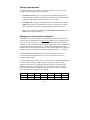
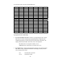
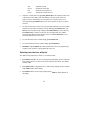
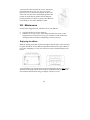
Micro-computer Electronic Time Clock
User Manual
For more information on
Acroprint products
Acroprint offers a complete line of standard Time
Recorders, state-of-the-art Electronic Time Recorders,
Document Time Stamps, Watchmen’s Systems,
HRx Human Resource Software, and
Time & Attendance Systems.
Time for Business….
5640 Departure Drive
Raleigh, NC 27616-1841
919.872.5800
In USA 800.334.7190
Fax: 919.850.0720
email: [email protected]
Visit our Web Site: www.acroprint.com
Register online at www.acroprint.com
©
All Rights Reserved. 2003
Acroprint Time Recorder Company
Table of Contents
I.
Introduction ................................................................................. 1
Overview..........................................................................................................1
Specifications ...................................................................................................1
Accessories ......................................................................................................1
Features ............................................................................................................2
II.
III.
IV.
Package Contents......................................................................... 2
Location of Components ............................................................. 3
Getting Started............................................................................. 3
Installing clock dial battery..............................................................................3
V.
Setting the ATR120...................................................................... 4
Programming Hints ..........................................................................................4
Selecting day of week ......................................................................................5
Setting the time ................................................................................................7
Setting the year, month, and date .....................................................................7
Setting Daylight Saving Time ..........................................................................8
Setting the day change time .............................................................................9
Setting the printing format ...............................................................................9
Setting the two-color printing and internal signal tone ..................................10
Setting signal duration ...................................................................................13
Setting auto column shift print position .........................................................13
Setting how the hour will print.......................................................................15
Setting the password ......................................................................................16
Exiting program mode ...................................................................................16
VI. Installing your ATR120 ............................................................. 16
Wall-mounting ...............................................................................................17
VII. Operating your ATR120 ............................................................ 18
VIII. Maintenance .............................................................................. 19
Replacing the ribbon ......................................................................................19
IX. Troubleshooting......................................................................... 20
Location of fuses............................................................................................21
Error codes .....................................................................................................21
I.
Introduction
Overview
The ATR120 is an electronic across-the-card time clock, which can be used for a
weekly or a biweekly pay period. The unique ATR121 Time Card offers a weekly
time card on the front and a biweekly time card on the back. The day progresses
across the card from left to right in six columns. This is accomplished by pressing
one of the card-positioning buttons (IN-OUT) on top of the clock. The pay period
(day of week) moves down the card, top to bottom. You may select the time of day
you want this “day change” to occur. You may also select the starting day of your
pay period during the easy set up procedure.
The ATR120 offers two-color printing so employee punches outside normal punch
times will print in RED allowing for quick and easy auditing of exception punches.
The built-in signal can be programmed to audibly denote start and stop work times.
The large analog clock face, not electronically synchronized with the digital display,
is easy to read from across the room.
With a built-in battery back-up, auto daylight saving adjustments and a perpetual
calendar, the ATR120 Time Clock will always print the correct time.
Specifications
Power Source: 115VAC/60Hz
Power Consumption: 0.3V
Clock Accuracy: ±3s per week
Ambient Temperature: 23°F~104ºF (-5℃~40℃)
Ambient Humidity: 20%~80%
Analog Clock: 1 AA Battery (1.5V)
Size: 8.1"W × 8.85"H × 4.93"D (205mm W × 225mm H × 125mm D)
Accessories:
To assure proper operation please use the accessories designed to work with the
ATR120.
ATR121 Weekly/Bi-Weekly Time Card. Part Number 09 9110 000
Model 120R Time Card Rack holds 25 ATR121 Time Cards.
Part Number 81 0120 000
ATR122 Two-Color Replacement Ribbon Cassette. Part Number 39 0127 000
1
Features
·
·
·
·
·
·
·
·
·
II.
Compact design for desktop or wall mounting
Weekly or bi-weekly pay periods
Digital display shows time and date and is synchronized with dot matrix printer
9-pin dot matrix printer that allows for 12 or 24-hour & 60/100 print format
Easily distinguish printing time between AM and PM. PM minutes or
hundredths are over scored 8:00 (8:00 PM)
2-color (red/black) cassette ribbon can be programmed so punches outside of
schedule will print in red
Built-in signal tone to denote start and stop times
Daylight Saving Time and perpetual calendar
Password for program protection
Package Contents
Unpack the time clock and check its contents to ensure that it and all of the
accessories shown below are included.
2
III.
Location of Components
1. Anti-dust cover
2. Time card receiver
3. In/Out advance buttons (6)
4. Analog clock (Clock dial)
5. Display
6. Program mode switch
7. Reset (return to original factory settings)
8. Wall-mounting keyholes
9. Fuse access door
IV. Getting started
Installing clock dial battery
The front cover must be opened before the clock dial battery can be installed.
Opening the front cover also allows you to set the clock's analog time. You will need
to do this occasionally to synchronize the clock dial to the digital display and printer.
3
To open the front
cover, turn the clock
on its back and
remove the two
outer screws on
bottom of clock.
Stand the clock
upright with the back facing you. With both thumbs press down on IN1 and OUT3
buttons while using your fingers to push cover away.
The clock dial panel is shipped locked into place. You have the option of removing
the tab that locks the clock panel into place for easy access when setting the clock. If
you remove the locking tab, we suggest you keep the tab. To remove the locking tab,
unfasten the screw located in the front cover and remove the screw and clip. The
screw and clip may be stored by securing it into the post screw hole below where it
was removed. It is not necessary to remove the locking tab to install the battery or to
adjust the clock dial time setting.
Once the front cover is open, you will be able to install the battery and to set the
time on the dial. Opening the front cover also allows you to access the ribbon
cassette.
V.
Setting the ATR120
Programming Hints
The ATR120 incorporates features to make the task of time and attendance faster and
easier.
The simplest way to program the ATR120 is to set all of the functions, at one time,
while in the program mode. Although, you may set functions independently it is
recommended that you follow the program sequence.
When programming the time, and the time of day for events to occur, the display
will show time in a 24-hour format (i.e. 3:00 PM will be 15:00).
To place the clock in the program mode, set the program switch located on back of
clock, in the upper left corner from “NOR” to “PRO” (top position). This now
activates the 6 manual card-positioning switches (“IN1”, “OUT1”, etc.) on top of the
4
clock to function as program switches. With the dust cover open you will find that
these program switches are numbered 1 – 6 to simplify programming the ATR120
The first switch on the top left of the clock (IN1) functions as the feature selection
switch and will advance you through the program mode. This switch also allows you
to skip over a feature and advance to the next feature without programming. Once a
feature is selected, switches “OUT2” through “IN3” will be used for programming.
We'll refer to the switches as buttons one through six.
The last switch on the right, button six or “OUT3” is used to save the program
selection to memory. IMPORTANT: If OUT3 is flashing in the lower right corner
of the display, the programmed changes have not been saved.
IN1
OUT1
IN2
OUT2
IN3
OUT3
O
O
O
O
O
O
1
2
3
4
5
6
Select
Save
ß-------------Programming Switches-------------à
(When in the PRO mode)
To return to the original factory settings press the “RESET” button located to the left
of the PRO/NOR switch on back of the clock.
Note: Each time you modify the program, you must press button six to save the
program changes. OUT3 flashes in the lower right corner of the digital display until
the programming change is saved. If OUT3 is flashing in the lower right corner of
the display, the program changes have not been saved.
Selecting day of week
The ATR120 can be programmed for either weekly or biweekly pay periods.
For weekly pay periods, program the time clock as follows:
·
Enter the programming mode by setting the switch on the back of the
ATR120 to the PRO position. The display indicates 1-31.
5
·
Press button four once. The display reads 2-1. The 2 indicates this is a
weekly pay period. OUT3 flashes in the lower right hand corner of the
display. This will flash until the changes are saved.
·
Press button five to choose the current day of the week for your weekly
pay period.
2-1 = Monday
2-2 = Tuesday
2-3 = Wednesday
2-4 = Thursday
2-5 = Friday
2-6 = Saturday
2-7 = Sunday
·
Press button six to save your settings. OUT3 is no longer displayed.
For biweekly pay periods, you must select the current day of week within the pay
period. Example: if the current day of the week (today) is Monday you must choose
which Monday, the first (3-1) or second Monday (3-8) of the pay period.
·
Enter the programming mode by setting the switch on the back of the
ATR120 to the PRO position. The display reads 1-31 or the last setting.
·
Press button four twice. The display reads 3-1. The 3 indicates this is a
biweekly pay period. OUT3 flashes in the lower right hand corner of the
display. This will flash until the changes are saved.
·
Press button five to choose the first day of your weekly pay period.
3-1
3-2
3-3
3-4
3-5
3-6
3-7
3-8
3-9
3-10
3-11
3-12
3-13
3-14
= first Monday of pay period
= first Tuesday of pay period
= first Wednesday of pay period
= first Thursday of pay period
= first Friday of pay period
= first Saturday of pay period
= first Sunday of pay period
= second Monday of pay period
= second Tuesday of pay period
= second Wednesday of pay period
= second Thursday of pay period
= second Friday of pay period
= second Saturday of pay period
= second Sunday of pay period
6
·
Press button six to save your settings. OUT3 is no longer displayed.
Setting the time
·
Make sure the ATR120 is in programming mode.
·
Press button one once to start setting the current time. This mode starts the
clock-timing device. The display indicates the time at which the clock is
currently set. Depending on how long you have been in the program mode, the
display may advance from the default setting of 00 5:00.
·
Press button four to set the hours (24-hour format; 0-23 with 0 = midnight).
The display reads 00 6:00 with OUT3 flashing in the lower right hand corner.
Advance to the correct hour. Note: Hold down button four to rapidly advance
the hour.
·
Press button five to set the minutes. The display reads 00 6:50 with OUT 3
flashing in the lower-right hand corner. Advance to the correct minutes.
·
Press button six to save the time setting. OUT3 disappears. The seconds reset to
0.
Setting the year, month, and date
·
Press button one once (twice if just entering the programming mode) to set the
year, month and date. The display indicates the last programmed year, month,
and date with the default being 99 1-1.
·
Press button three to set the year. The display reads 00 1-1 with OUT 3
flashing in the lower right-hand corner of the display. Press button three until
the correct year is set.
·
Press button four to set the month (1-12, with 1= January, 2 = February, etc.)
OUT3 flashes in the lower-right hand corner of the display. Press button four
until the current month is set.
·
Press button five to set the date. OUT3 flashes in the lower-right hand corner of
the display. Press button five until the current date is set.
·
Press button six to save the year, month, and date settings. The display should
show the correct month and date.
7
Setting Daylight Saving Time
·
Press button one once. If you are entering the programming mode for the first
time, you will need to press button one three times to set Daylight Saving Time.
The display reads S1 0-0 with S1 indicating the start of Daylight Saving Time.
·
Press button four to set the month (1-12, with 1= January, 2 = February, etc.)
The display reads S1 0-0 with OUT3 flashing in the lower-right hand corner of
the display. Press button four until the month Daylight Saving Time should start
is set.
·
Press button five to set the day of the month. OUT3 flashes in the lower-right
hand corner of the display. Press button five until the day Daylight Saving Time
should start is set.
·
Press button six to save the month and day Daylight Saving Time should start.
OUT3 will no longer be displayed indicating this setting has been saved. The
program will automatically switch to setting the ending date for Daylight
Saving Time. The display should now read S2 0-0.
The ending date for Daylight Saving Time is set exactly the same as the beginning
date.
·
Press button four to set the month (1-12, with 1= January, 2 = February, etc.)
The display reads S2 0-0 with OUT3 flashing in the lower-right hand corner of
the display. Press button four until the month Daylight Saving Time should end
is set.
·
Press button five to set the day of the month. OUT3 flashes in the lower-right
hand corner of the display. Press button five until the day Daylight Saving Time
should end is set.
·
Press button six to save the month and day Daylight Saving Time should end.
OUT3 will no longer be displayed indicating this setting has been saved. The
display will return to the starting date.
Note: The starting and ending dates for Daylight Saving Time must be set each
year. Both the starting and ending dates must be set for Daylight Saving Time to be
operational. At midnight on the starting date, the clock will automatically advance
one hour. At midnight on the ending date, the clock will go back one hour. For
8
example, on the first date of Daylight Saving Time, the clock will advance from
midnight to 01:00. At midnight on the last day, the clock will change from 00:00 to
23:00.
Setting the day change time
·
Press button one once. If you are entering the programming mode for the first
time, you will need to press button one four times to set the Day Change Time.
The display should read 5:00, indicating the day change time. Five o'clock AM
is the default time for the day change to take place. This is the time that the
ATR120 will change to printing the time on the next row for the next day. You
may want to change this to another time, such as midnight (00:00).
·
Press button four to adjust the hour (00~23h) the day change should take place.
OUT3 flashes in the lower right-hand corner of the display indicating this
setting has not been saved.
·
Press button six one time to save the day change time setting.
Setting the printing format
The ATR120 will print in standard minutes (60) or in decimal hundredths (100) of an
hour. For example, 12:45 will be printed 12:45 in the standard minute format or as
12.75 if hundredths is chosen. PM hours are indicated by minutes being over scored.
Example: Two fifteen in the afternoon would print as 02:15 in 12-hour format or
14:15 in 24-hour format.
·
Press button one once. If you are entering the programming mode for the first
time, press button one five times to set the printing format. The display should
now read Cd 60, indicating the ATR120 is set to print standard minutes.
·
Press button five to change the printing format. The display will toggle back
and forth between Cd 60 and Cd 100 with OUT3 flashing in the lower
right-hand corner. Cd 100 represents minutes being printed in a decimal
hundredths format.
·
Press button six once to save the print format. OUT3 will no longer be
displayed.
9
Setting the two-color printing and internal signal tone
Time cards can be audited much easier by highlighting in red, punches outside the
normal work schedule. Using the internal audible signal will remind your employees
of start and stop times in their work schedule. You can even have a warning signal
two minutes before start time to alert your employees. This program allows for a
total combination of 32 scheduled events. Events can be selected to allow a ribbon
color change or a signal tone or a combination of both. Each event can be
programmed for the time of day in hours and minutes and the day of week.
The events available are:
Clock to print in RED
Clock to print in RED with SIGNAL
Clock to print in BLACK
Clock to print in BLACK with SIGNAL
Clock to SIGNAL without a color change
Note: The default ribbon color is black. The clock has to be programmed at a
specific time to print in red. Once a color change occurs the clock will print in that
color until an opposite color change is activated.
The following is a sample schedule of events for a 8:00 AM to 5:00 PM work
schedule with a one hour lunch period from 12:00 Noon to 1:00 PM (13:00) This
schedule has the clock printing in RED at 8:01 AM to 12 Noon. Any late in or early
out punches will print in RED, The clock will print in BLACK during the lunch
period. Then printing in RED at 1:01 PM (13:01) until 5:00 PM (17:00). At 5:00 PM
the clock will print in BLACK allowing for exit punches. At 5:30 (17:30) the clock
will return to RED to note OT punches or late outs. The clock will return to BLACK
at 07:30 in the morning to allow for IN punches for that day. The internal signal will
sound at 8:00 AM, 12:00, 1:00 PM and 5:00 PM audibly notifying start and stop
times. On the chart on the next page, the IN/OUT under each event denotes the event
selection shown on bottom of the display during the programming of these events.
10
Event
Max 32
1
2
3
4
5
6
7
8
Print in
Red
IN1
Print in
Black
OUT1
Signal
Only
IN2
08:00
Print Red &
Signal
IN1 IN2
Print Black
& Signal
OUT1 IN2
08:01
12:00
13:00
13:01
17:00
17:30
07:30
Event
1
2
3
Time
8:00
8:01
12:00
4
5
13:00
13:01
6
17:00
7
8
17:30
07:30
Description of Event
SIGNAL Only to denote start of work schedule
Color changes to RED to denote late or early lunch punches
SIGNAL noting start of lunch period and color change to
BLACK SIGNAL
SIGNAL Only to denote end of lunch period
Color change to RED to show late in punches or early end of
day out punches
SIGNAL to denote end of work schedule and color change to
BLACK
Color change to RED to indicate possible overtime
Color change to BLACK to allow morning in punches
When the display shows 01 5:00
Press button two to select the event (IN1, print in red or OUT1, print in black, etc.)
Press button three to confirm the event (OUT3 will continue to flash).
Press button four to select the hour of the event.
Press button five to select the minute the event will occur.
To have the event occur each day (Recommended), press button six to save the
event and advance to the next scheduled event, 02 5:00.
If you do not want an event to occur each day, you may select the day(s) of the week
you want the event to occur. After selecting the minute the event will occur, press
button two. At the bottom of the display, the event indicator will be displayed and
OUT 3 will be flashing. As the top of the display, SUN will be flashing. To select
SUN, press button three or to advance to MON, press button two. Remember to use
button three to save the day of the week. Cycle between buttons two and three as
11
necessary to set the day(s) the event should occur on. The event will occur on the
day(s) shown across the top of the display.
It is recommended that a program chart be used to create a schedule to assist in
programming this feature. The typical company uses eight events, similar to the
previous example on page 11.
Program
Print in
Red
IN1
Print in
Black
OUT1
Signal
IN2
1
2
3
4
5
6
7
8
9
10
11
12
13
14
15
16
17
18
19
20
21
22
23
24
25
26
27
28
29
30
31
32
12
Print Red &
Signal
IN1 IN2
Print Black
& Signal
OUT1 IN2
Setting signal duration
The ATR120 can be set to produce a signal lasting from zero (0) 0 to sixty (60)
seconds, with the default being five (5) seconds.
·
Press button one once. If you are entering the programming mode to set or
adjust of the signal duration, press button one seven times. The display should
now read 5, indicating the signal will sound for five seconds.
·
Press button five to change the signal duration. The display indicates 5 with
OUT3 flashing in the lower right-hand corner. The 5 represents five seconds.
Press the fifth button to choose the signal duration from 0 to 60 seconds.
·
Once you have chosen the signal duration, press button six one time to save it.
OUT3 will no longer be displayed.
Setting auto column shift print position
This feature may not be appropriate for all installations. The auto column shift is a
special feature for installations where most or all employees arrive and depart at the
same time. Employees who arrive or depart at different times may be required to
manually reset the card column position. Failure to do so will result in printing in the
wrong location on the time card. For ease of operation of the ATR120, caution
should be used in selecting this feature. If the auto column shift position is manually
changed, the clock will return to the scheduled auto position after 7 – 8 seconds.
The auto column shift feature allows for a total of 18 horizontal moves. It is
recommended that a program chart be used to create a schedule to assist in
programming this feature.
A sample program chart is shown below for an 8:00 AM to 5:00 PM shift with lunch
between 12:00 Noon and 1:00 PM. Employees may punch in after 7:30 AM.
Employees start lunch at 12:00 PM and must take at least a 15-minute lunch to
punch in IN2 column. AT 5:00 PM the clock will advance to OUT2. Overtime
punching is allowed after 5:30 PM. And a minimum of 30 minutes is permitted
before moving to the column OUT3 at 6:00 PM.
EVENT
1
2
IN1
07:30
OUT1
12:00
IN2
12:15
13
OUT2
17:00
IN3
17:30
OUT3
18:00
Use this chart to plan your Auto Column Shift times.
EVENT
01
02
03
04
05
06
07
08
09
10
11
12
13
14
15
16
17
18
IN1
OUT1
IN2
OUT2
IN3
OUT3
To program the auto column shift:
·
Press the first button one time to advance to programming the auto column
shift feature. If you are entering the programming mode to adjust the auto
column shift position you will need to press the first button eight times. The
display indicates 01 5:00 with all days of the week displayed.
01 indicates the event sequence number (01-18).
5:00 indicates the default time (5:00 AM) of the event
·
Press button two to advance through column selections. The column position
(IN1, OUT1, icons) will flash at the bottom of the display. The day of week
icons are displayed at the top.
IN1
OUT1
First In Punch of the shift
Out Punch (Lunch)
14
IN2
OUT2
IN3
OUT3
In Punch (Lunch)
Out Punch end of shift
In Punch Overtime Period
Out Punch Overtime Period
·
Select the column position by pressing button three. The column position icon
at the bottom of the display will stop flashing. ALL days of the week will
appear at the top of the display. To select this move everyday of the week
(recommended), press button six to select and to advance to the next column
selection.
·
To select certain day(s) of the week, after pressing button three to select column
position (icon at bottom of display will stop flashing), press button two, and
SUNday icon will flash at top of display. Press button three to select that day.
Press button two to advance to the next day. Pressing button two without
pressing button three will skip that day of the week. Press button six to save
selections and advance to next event.
·
To select the hour for the column change, press button four.
·
To select the minutes for the column change, press button five.
·
Remember to press button six to save and advance to the next programming
sequence. Each sequence is programmed the same way.
Selecting how the hour will print
The ATR120 will print hours in either 12- or 24-hour format.
·
Press button one once. If you are entering the programming mode to adjust the
hour printing format, you will need to press button one nine times. The default
setting is 24H.
·
Press button four to toggle between 12- and 24-hour printing format (12H and
24H). OUT3 flashes on the display.
·
Press button six to save the hour printing format. OUT3 no longer flashes on
the display.
15
Setting the password
The ATR120 allows for the use of a four-digit number as a password to protect
programmed settings. When the password is set, you will be asked to enter it each
time you enter the programming mode. It is recommended that if a password is used
that you write it down and store it in a safe place. If an incorrect password is entered
you will be prevented from entering the programming mode. Note: If correct
password cannot be entered, the clock can be reset to original settings by pressing
the “RESET” switch on back of clock next to the program switch. Doing so will
reset ALL functions, requiring the ATR120 to be re-programmed.
·
Press button one once. If you are entering the programming mode to set or
adjust the password, press button one ten times. The display indicates 00 00.
·
Press button four to choose the first two digits of the password. You may use
any digits from 00 to 99. OUT3 flashes in the lower right corner of the display.
·
Press button five to choose the last two digits of the password. You may use
any digits from 00 to 99. OUT3 flashes in the lower right corner of the display.
·
Press button six one time to save the password setting. The flashing OUT3
disappears.
Once the password has been set, when you enter the program, the ATR120 will
display 0000. The password must be entered and button six pressed, then the time
clock will display and enter program mode. If the password is incorrect, then the
ATR120 will beep and Error Message E-40 is displayed. You will not be allowed to
enter the programming mode until the correct password is entered.
Exiting program mode
When you have finished programming the ATR120, reset the program switch on the
back of the clock, to the NOR position and press button one once to return to the
normal mode. The ATR120 will now display the current time and date and is ready
for operation.
VI.
Installing your ATR120
The ATR120 can be installed in any normal office environment. It may be installed
on a smooth, flat surface or wall-mounted. No special wiring is needed. However,
16
we recommend installing the ATR120 on a separate power circuit. We do not
recommend using a power strip. Always follow basic safety precautions when using
this product to reduce the risk of injury, fire, or electric shock.
Caution:
· Read and understand all instructions in the ATR120 User's Manual before
installing and operating this time clock.
· Do not install the ATR120 in areas where it may be exposed to direct sunlight or
high temperatures, such as near a heater.
· Do not install the ATR120 where it may be exposed to excessive dust or to high
humidity, resulting in condensation.
· Do not use this product near water or when you are wet. If the product comes in
contact with any liquids, unplug the electric cord immediately. Do not plug the
product back in until it has thoroughly dried.
· Securely install the time clock on a stable, level surface, or if wall mounting the
ATR120, follow the wall mounting instructions to install it securely on the wall.
Place the time clock where no one can step or trip over the cord. Do not place
objects on the power cord that can cause damage or abrasion.
· If this product does not operate normally, please consult the “Troubleshooting”
section of this manual.
Wall-mounting
1. Following the diagram, insert a screw about 94cm to 124cm above the floor.
Allow about 1/8" between the screw head and the wall.
17
2. Following the diagram, insert screws at
positions B and C. Place a screw anchor
in the wall at position D.
3. Use the two screws
(M4X10) to attach
the wall-mounted
frame to the bottom
of the time clock.
4. Line up the keyholes on the back of the time clock with
the screws in the wall. Slide the ATR120 downwards to
firmly mount it on the wall.
5. Place a screw in the bottom hole of the
wall-mounting frame to secure it to the
wall.
VII. Operating your ATR120
The Clock will print in the column indicated by the red light above the IN/OUT
buttons. Press the appropriate IN or OUT button to choose the print position for time
cards. The print position will not change until another column button is pressed. If
an auto shift schedule is programmed, then the ATR120 will automatically shift from
column to column. If manually changed, while in auto shift, the clock will return to
the programmed position after 7 or 8 seconds.
In Morning/Out Lunch
IN1
OUT1
IN Lunch/Out End of Day
IN2
OUT2
18
OT In/OT Out
IN3
OUT3
To print, insert a time card into the receiver with the pay
period selected, facing you. Note: The clock cannot
differentiate the pay period and will print on either side
of the time card. The card is automatically pulled in and
printed. Do not attempt to pull the card out during the
printing operation or to insert any objects other than time
cards. Doing so can result in damage to printer.
VIII. Maintenance
Several simple suggestions may extend the life of your ATR120.
·
·
Close the anti-dust cover after operation.
When the case is dirty, wipe it with a damp soft cloth. If necessary, a mild
detergent may be used. Do not use any type of thinner or other chemical for
cleaning because the chemical could damage or discolor the case.
Replacing the ribbon
When the printing on the time card becomes light or hard to read it will be necessary
to replace the ribbon. Use the ATR122 replacement ribbon cassette (part number 39
0127 000). Attempting to “re-ink” the cassette will cause permanent damage to the
printer.
To open the front cover, turn the clock on its back and remove the two outer screws.
Stand the clock upright with the back facing you. With both thumbs press down on
IN1 and OUT3 buttons while using your fingers to push cover away.
19
Next, remove and discard the pin and
clip. Remove the ribbon cassette by
first sliding it left and then upwards as
shown by the illustration (A & B).
Place the new ribbon into the ATR120.
It is not necessary to replace the pin and
clip. Turn the ribbon feed knob
counterclockwise until the ribbon is taut.
Close the front cover.
IX. Troubleshooting
Problem
Clock does not accept
time cards
Possible Cause
AC power is OFF
Power cord is disconnected
AC fuse blown
DC fuse blown
Still in program mode
Printing light
Worn ribbon
Ribbon cassette not seated
correctly
Incorrect pay period starting
day
Time card inserted
incorrectly
Printing head fuse blown
Printing in wrong
position
Not printing
Clock stopped
Analog clock slow or
stopped
Ribbon cassette not seated
correctly
AC power is off
Power cord is disconnected
AC fuse blown
Battery weak
Out of synchronization
20
Check
Restore power
Restore cord to outlet
Replace AC240V 1A fuse
Replace DC 12V 2A fuse
Return switch to NOR
position
Replace ribbon cassette
Reinstall ribbon cassette
Set correct day
Insert card correctly
Replace DC 12V 1.5 Amp
fuse
Reinstall ribbon cassette
Restore power
Restore cord to outlet
Replace AC240V 1A fuse
Replace AA battery
Reset to digital display
Location of fuses
The fuse panel is located on the back of the ATR120 in the lower left corner. To
access fuses, disconnect the power from the clock and remove the screw securing
door. Replace blown fuse with only the same rated fuse. Do not substitute.
1. Printer Head Fuse (1.5A DC 12V)
2. AC Fuse (1A AC 240V)
3. DC Fuse (2A DC 12V)
Error Codes
The ATR120 has built-in diagnostics to guide you in maintaining your time clock.
These Error Codes, when occurring, will be seen on the display.
Code
E-01
Meaning of Error
Clock motor or sensor failure
E-03
E-05
E-30
E-33
Card positioning
Card does not feed correctly
Printer head fails to return to home
position
Can’t change color
E-35
The card can’t be returned
E-37
E-38
E-40
Sensor cannot locate card
Printer head jammed
Wrong password entered
21
Check
Unplug and reconnect power cord
or turn the program switch on-off
twice, letting the clock readjust.
Contact dealer or factory
Re-insert card and print.
Contact dealer or factory
Check that the ribbon is installed
correctly.
Contact dealer or factory
Make sure there are no
obstructions in card receiver
Contact dealer or factory
Contact dealer or factory
Contact dealer or factory
Enter the correct password
For any other Error Codes contact your dealer or Acroprint Time Recorder.
To return to the original Factory settings, press the reset switch, located on the back
of the clock next to the PRO switch. When resetting the clock make sure the
PRO/NOR is in the NOR position. After resetting enter the PRO mode to reprogram
the clock.
22
5640 Departure Drive
Raleigh, NC 27616
919.872.5800
IN USA 800.334.7190
www.acroprint.com
P/N 06-0314-000 Rev. A