1
Planning Instruction 66571758GB0
49/2011
Fire Detection
FX 3NET + SLC FIRE ALARM SYSTEM
Part 1: General Rules
These are the planning instructions for an FX 3NET fire detection and alarm system
consisting of
FX 3NET, FXL 3NET, FXM 3NET and FXS 3NET control panels
SLC compatible intelligent field devices
In this document FX refers to all FX 3NET, FXL 3NET, FXM 3NET and FXS 3NET panels. For
information specifically related to a specific panel model, that model type is indicated.
We reserve the right to make technical changes without notice.
The planning instructions consist of 3 parts:
Part 1: General Rules 6657 1758GBx
Part 2: System Devices 6657 1759GBx
Part 3: Additional Information 6657 1760GBx
See also the following instructions:
User guide of the WinFX3Net Configuration Tool 6657 1782GBx
FX3Net Configuration Data 6657 1783GBx
FX3Net System Capacity Calculation Tool 6657 1746GBx
Note!
Instructions given by local authorities must be followed when planning the system.
Planning Instruction 66571758GB0
Fire Detection
2
1. About planning the system ............................................................................................................................... 3 1.1 When is a fire alarm needed? ................................................................................................................... 3 1.2 Planning an automatic fire alarm system................................................................................................ 3 1.3 Regulations ................................................................................................................................................ 4 1.4 Example of a site plan for the FX 3NET fire detection system.............................................................. 5 2. General description of the FX 3NET system.................................................................................................... 6 2.1 Standalone FX 3NET or FXL 3NET fire detection system...................................................................... 6 2.2 Standalone FXM 3NET fire detection system ......................................................................................... 6 2.3 FXS 3NET fire detection panel.................................................................................................................. 7 2.4 Networked FX 3NET fire detection system.............................................................................................. 7 2.5 FX 3NET stand-alone system diagram .................................................................................................... 8 2.6 Networked FX 3NET system diagram ...................................................................................................... 9 3. FX 3NET, FXL 3NET, FXM 3NET and FXS 3NET construction ..................................................................... 10 3.1 FX 3NET cabinet....................................................................................................................................... 10 3.2 FXL 3NET cabinet .................................................................................................................................... 11 3.3 FXM 3NET cabinet.................................................................................................................................... 11 3.4 FXS 3NET cabinet .................................................................................................................................... 11 3.5 FX battery cabinet.................................................................................................................................... 12 3.6 FXM battery cabinet................................................................................................................................. 12 4. Mechanical installation .................................................................................................................................... 13 4.1 Installation, FX 3NET and FXL 3NET control panels............................................................................ 13 4.2 Installation, FXM 3NET control panel .................................................................................................... 14 4.3 Installation, FXS 3NET control panel ..................................................................................................... 15 5. FX 3NET, multi-panel networked system ....................................................................................................... 16 5.1 Seeing and visible panels ....................................................................................................................... 16 5.2 Site plan table of seeing – visible panels .............................................................................................. 18 5.3 Interpanel communication ...................................................................................................................... 19 5.4 Networked FX 3NET main parameters................................................................................................... 19 6. Addressable detection circuits, addresses, zones ....................................................................................... 20 6.1 FX-SLC addressable detection circuits and addresses....................................................................... 20 6.2 Detection zones ....................................................................................................................................... 21 6.3 FX-SLC Addressable detection circuit structure.................................................................................. 21 6.4 FX control groups .................................................................................................................................... 23 6.4.1 Control groups for all event types (Ctrl A and Ctrl B)...................................................................... 24 6.4.2 Control groups for fire event input and outputs in loop addresses (CG1 + D ... CG7 + D).......... 24 6.4.3 Control group use for phased evacuation ........................................................................................ 25 6.4.4 Control group use for delayed alarm................................................................................................. 26 6.5 Number of devices between short circuit isolators ............................................................................. 27 6.6 Number of devices in an addressable detection circuit ...................................................................... 27 7. FX-CLC Conventional detection circuits........................................................................................................ 28 7.1 Conventional detection circuit controller (CLC)................................................................................... 28 7.2 Compatible conventional detectors and manual call points............................................................... 28 7.3 Conventional detection circuit structure and End-of-Line resistors.................................................. 29 7.4 Configurable options............................................................................................................................... 29 8. Cabling............................................................................................................................................................... 30 8.1 Cables of addressable detection circuit................................................................................................ 30 8.2 Cables of conventional detection circuits CLC, alarm device lines, input/output lines .................. 31 8.3 Cables of serial communication lines and power supply.................................................................... 32 8.4 Grounding of communication cables .................................................................................................... 33 8.5 Battery backup calculation ......................................................................................................................... 34 9. FX 3NET, FXL 3NET, FXM 3NET and FXS 3NET Technical data .................................................................. 35 9.1 Technical data, standard panels ............................................................................................................ 35 Schneider Electric Pelco Finland Oy Kalkkipellontie 6, 02650 Espoo, Finland
Document Number 66571758GB0
Telephone: +358 10 446 511
Fax: +358 10 446 5103
49 2011
www.pelco.com/nordic
© 2009 Schneider Electric. All rights reserved.
Contents
Planning Instruction 66571758GB0
1.
About planning the system
1.1
When is a fire alarm needed?
Fire Detection
3
Fire detection and alarm systems are installed mainly to protect human life. The early detection of smoke sensor
alerts people to evacuate the building in an orderly manner. Alarm devices provide a sufficient signal to warn
people.
Fire detection and alarm systems are also installed on premises where stock, machinery or other property need to
be protected. A fire detection system gives an early indication, making it possible to start and finalise the rescue
work quickly, thus allowing normal activities to continue without delay.
If getting a building permit requires installation of a fire alarm system, a sufficient degree of coverage must be
provided. The extent of such coverage is specified in national and international regulations.
1.2
Planning an automatic fire alarm system
The automatic fire detection system should be planned and installed in a way that guarantees that a fire starting in
the area to be surveyed is detected as early as possible and a fire alarm indicating the location is activated. Faults
that might jeopardise the reliability of the fire detection system should also be reported. If needed (for example, for
quotation purposes) a preliminary plan should be made as well as an installation plan for the detection system.
Preliminary plan
The preliminary plan can be made by the electrical engineer, the contractor or the manufacturer's representative.
Installation plan
The installation plan is made by the manufacturer's representative or an authorised fire detection and alarm
planning engineer. The plan includes:
•
Selection of detector types and manual call points and specifying their location, taking into consideration
coverage, environment, building construction, etc.
•
Selection of types of alarm devices (bells, sirens, beacons etc.) and specifying their location to ensure that
everybody in the building is alerted.
•
Selecting cable types and planning the routing of the cables within the building.
•
Specifying any control functions needed for fire protection, such as signals to extinguishing systems,
ventilation systems, fire doors or shutters etc.
•
Taking into consideration any additional requirements from the fire authorities.
© 2009 Schneider Electric. All rights reserved.
It may be a requirement by the local fire authorities that the plan is inspected and approved by a third party before
the installation commences.
Schneider Electric Pelco Finland Oy Kalkkipellontie 6, 02650 Espoo, Finland
Document Number 66571758GB0
Telephone: +358 10 446 511
Fax: +358 10 446 5103
49 2011
www.pelco.com/nordic
Planning Instruction 66571758GB0
1.3
Fire Detection
4
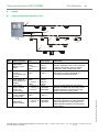
Regulations
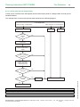
EN54-14 “Guidelines for Planning, Installation, Commissioning and Maintenance” defines good general guidelines
for planning. Local specific regulations must also be followed.
The main planning and documentation phases are described in the diagram below. A typical lay out drawing
including devices is found in the section 1.4.
End user
Maintenance
Third party periodical inspection
Maintenance
Use
Installation
Commissioning
Third party approval and/or handover
Commissioning and verification
Initialisation and configuration
Alteration,
modification or
extension
Installation
Planning
Planning and design
Assessment of needs or
Risk Assessment
© 2009 Schneider Electric. All rights reserved.
Initial concept
Standard EN54-14: Guidelines for planning
Schneider Electric Pelco Finland Oy Kalkkipellontie 6, 02650 Espoo, Finland
Document Number 66571758GB0
Telephone: +358 10 446 511
Fax: +358 10 446 5103
49 2011
www.pelco.com/nordic
Planning Instruction 66571758GB0
1.4
Fire Detection
5
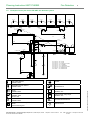
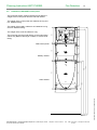
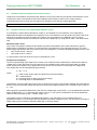
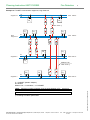
Example of a site plan for the FX 3NET fire detection system
001
002
01.014
003
004
01.015
005
01.016
01.017
006
01.018
007
01.019
01.020
01.024
01.013
01.012
XE
01.021
01.022
01.023
016
008
To FCP-1
24 VDC
(From FCP-1)
CTLE
CTLE
01.011
011
01.001
01.002
01.003
01.010
01.005
012
01.004
009
010
01.161
To FIRE DOOR
01.006
RE
015
01.101
013
CZ
CONTROL PANEL
01.151
FCP-1
C
CTLE
60°
01.009
001
002
003
004
005
006
007
008
C
01.102
60°
OFFICE
OFFICE
OFFICE
OFFICE
OFFICE
OFFICE
OFFICE
LOBBY
009
010
011
012
013
014
015
016
TOILET
TOILET
ELECTRICAL ROOM
CLEANING
LOADING BAY
ELECTRICAL ROOM
WAREHOUSE
WAREHOUSE
CTLE
XE
01.008
C
60°
01.007
CTLE
Multi-criteria detector
Installation base
Sounder
Addressable smoke detector
Installation base
Sounder/beacon
Addressable smoke detector with short circuit
isolator
Installation base
Addressable smoke detector
Installation base
Remote LED
Addressable heat detector
Installation base
Addressable manual call point with short circuit
isolator
Surface mounting box
Schneider Electric Pelco Finland Oy Kalkkipellontie 6, 02650 Espoo, Finland
Document Number 66571758GB0
CZ
Conventional zone module
Installation box
RE
Control module, relay output
Installation box
C
60°
1
© 2009 Schneider Electric. All rights reserved.
014
Conventional heat detector
Detection circuit
Telephone: +358 10 446 511
Fax: +358 10 446 5103
49 2011
www.pelco.com/nordic
Planning Instruction 66571758GB0
Fire Detection
2.
General description of the FX 3NET system
2.1
Standalone FX 3NET or FXL 3NET fire detection system
Main features
The modular design of the FX 3NET and FXL
3NET 2, 4, 6, or 8 loop control panel offers a
competitive solution for small and medium sized
projects. The address capacity of the detection
circuits also offers flexibility for cabling, thus
saving costs in installation work.
A wide range of intelligent detectors provides
solutions for all applications. In addition,
conventional detectors can be connected to
interface modules, making an upgrade of a former
conventional system flexible.
In many tests, the high-sensitive laser detectors
have proved to be even more efficient than the
aspiration detection systems often used in, for
example, computer rooms.
The I/O-modules are economical and save space
in installation, and provide monitoring and control
functions.
With the extensive configuration software, all
addresses and many control functions of the panel
can be adopted for the requirements of the
installation site.
The communication capability makes it possible to
connect a standard printer and additional alarm
display panels.
FX 3NET and FXL 3NET standalone system
metrics
2 ... 8 addressable detection circuits
159 intelligent detectors + 159 I/O-modules per
detection circuit
250 detection zones
512 detectors and manual call points / EN54
regulation
2,544 addresses totally
17 Ah (internal in FX), 34 Ah (external), 51 Ah
(external) or 68 Ah (external) batteries
1.0 A total load in normal condition and 4.0 A total
load in alarm condition
Standalone FXM 3NET fire detection system
Main features
The FXM control panel offers the same features as
the FX and FXL panels, but in a smaller format, with
a smaller power supply and with less space for I/O
controllers.
Application areas
Protectable area up to 15,000 m²
(512 addresses – EN54)
Industrial sites
Lodging houses
Elderly service centres
Day care centres
Educational buildings
Note!
Application areas
Protectable area up to 15,000 m²
(512 addresses – EN54)
Business and office buildings
Industrial sites
Lodging houses
Service centres
Health and nursing centres
Educational buildings
FXM 3NET standalone system metrics
1 ... 4 addressable detection circuits
159 intelligent detectors + 159 I/O-modules per
detection circuit
250 detection zones
512 detectors and manual call points / EN54
regulation
1272 addresses totally
12 Ah (internal) or 34 Ah (external) battery capacity
0.5 A total load in normal condition and 2.2 A total
load in alarm condition
When the INFO serial communication is used, the maximum address capacity per detection circuit is
214: lower address range 1...159 + higher address range 201...255.
Schneider Electric Pelco Finland Oy Kalkkipellontie 6, 02650 Espoo, Finland
Document Number 66571758GB0
Telephone: +358 10 446 511
Fax: +358 10 446 5103
49 2011
www.pelco.com/nordic
© 2009 Schneider Electric. All rights reserved.
2.2
6
Planning Instruction 66571758GB0
2.3
Fire Detection
FXS 3NET fire detection panel
Main features
The FXS control panel offers the same features as
the FX and FXL and FXM panels, but in a smaller
format and without any built-in power supply unit. In
the FXS panel, there is one card slot for an option
board.
FXS 3NET standalone panel metrics
1 ... 2 addressable detection circuits
159 intelligent detectors + 159 I/O-modules per
detection circuit
250 detection zones
318 detectors and manual call points
636 addresses totally
Note!
2.4
The power supply feed has to be brought
from an FX 3NET, FXL 3NET, or FXM 3NET
panel.
Networked FX 3NET fire detection system
Application areas
Protectable area up to 500,000 m²
Business and office complexes
Industrial sites
Hotels
Service centres
Hospitals
Educational buildings
FX NET system metrics
32 FX 3NET, FXL 3NET, FXM 3NET and
FXS 3NET panels
256 interpanel logical connections
(seeing – visible connections)
255 addressable detection circuits
8,000 detection zones
16,384 detectors and manual call points / EN54
regulations
81,408 addresses totally (32 x FX capacity)
Properties of the FX panels, see section 2.1, 2.2
and 2.3
When the INFO serial communication is used, the maximum address capacity per detection circuit is
214: lower address range 1...159 + higher address range 201...255.
© 2009 Schneider Electric. All rights reserved.
Note!
7
Schneider Electric Pelco Finland Oy Kalkkipellontie 6, 02650 Espoo, Finland
Document Number 66571758GB0
Telephone: +358 10 446 511
Fax: +358 10 446 5103
49 2011
www.pelco.com/nordic
Planning Instruction 66571758GB0
2.5
Fire Detection
8
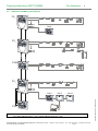
FX 3NET stand-alone system diagram
FX_
Addressable detectors, alarm devices and manual call points
Addressable special
detectors
1
2
Addressable I/O units
Input
4 5
3
6
7
2
10 9 8
x10
4 5
3
6
7
2
8
10 9
4 5
3
6
7
2
10 98
C
4 56
3
7
2
1 0 98
4 5
6
3
7
2
10 9 8
x10
x10
C
Output
4 5
6
3
7
2
10 9 8
4 5
3
6
7
2
10 9 8
C
4 5
3
6
7
2
10 98
x10
C
Conventional sounders
Outputs
Conventional detectors and manual call points
Inputs
Conventional alarm devices
Conventional detectors and manual call points
Intrinsically safe fire detectors and call points
Ex
PRESSHERE
DAPX
REPX
MCOX
External system
Note!
When the INFO serial communication is used, the maximum address capacity per detection circuit is
214: lower address range 1...159 + higher address range 201...255.
Schneider Electric Pelco Finland Oy Kalkkipellontie 6, 02650 Espoo, Finland
Document Number 66571758GB0
Telephone: +358 10 446 511
Fax: +358 10 446 5103
49 2011
www.pelco.com/nordic
© 2009 Schneider Electric. All rights reserved.
FMPX
Planning Instruction 66571758GB0
2.6
Fire Detection
9
Networked FX 3NET system diagram
FX_
1
2
FMPX
FX_
1
4 5
3
6
7
2
1 0 9 8
4
3
2
10
5
9
4
3
2
10
6
7
8
x10
5
9
6
7
8
4 5
3
6
7
2
8
10
9
x10
C
2
C
FXM
1
2
FX_
REPX
MCOX
FXS
Note!
When the INFO serial communication is used, the maximum address capacity per detection circuit is
214: lower address range 1...159 + higher address range 201...255.
Schneider Electric Pelco Finland Oy Kalkkipellontie 6, 02650 Espoo, Finland
Document Number 66571758GB0
Telephone: +358 10 446 511
Fax: +358 10 446 5103
49 2011
www.pelco.com/nordic
© 2009 Schneider Electric. All rights reserved.
FMPX
Planning Instruction 66571758GB0
3.
Fire Detection
10
FX 3NET, FXL 3NET, FXM 3NET and FXS 3NET construction
The FX panel is a modular construction, facilitating easy expansion and selection of required modules. The panel
consists of a back plate in sheet metal, specially designed racks that hold the electronic boards and a cover in
plastic. Two different cabinet types are available for housing the control panel and, in addition, a cabinet with a
blank cover is available for housing batteries or auxiliary equipment.
The electronics are distributed on boards as follows:
FX-UI2 – the User Interface board contains an LCD display, LEDs and buttons
FX-MC2 – the Main Controller contains the main and assistant processors and also basic mandatory inputs
and outputs
FX-PS_ – the Power Supply unit contains circuits for standby battery charging, voltage regulation and
power supply to the panel and external devices
FX-SLC – the Loop Controller for AP200 series devices
FX-LC – the Loop Controller for 200 series devices
FX-CLC – the Loop Controller for 16 input lines
FX-IOC – the Input/Output Controller provides clean contact signal inputs, clean contact signal outputs and
alarm device outputs
FX-OCA – the Output Controller for 16 clean contact outputs
REPX-OB – the Protocol Repeater duplicates the INFO-communication line
MCOX-OB – the Control Unit controls for logical control function
ZLPX-IC – the Controller controls OC-100L and OC-100R output boards
Signalling between the boards goes through a ‘motherboard’ between the racks (except REPX-OB, MCOX-OB and
ZLPX-IC).
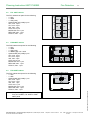
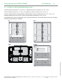
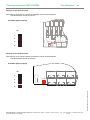
3.1
FX 3NET cabinet
MC2
OP
PS
OP
B
B
© 2009 Schneider Electric. All rights reserved.
The FX cabinet has space for the following
- 1 x UI2
- 1 x MC2
- 1 x PS (4,0A)
- 2 x Battery (B) 12V / 17Ah
- Option board (OP) totally 5 pcs:
SLC, max. 4 pcs
CLC, max. 4 pcs
IOC, max. 4 pcs
OCA, max. 4 pcs
MCOX-OB, max. 1 pcs
REPX-OB, max. 1 pcs
ZLPX-IC, max. 1 pcs
Schneider Electric Pelco Finland Oy Kalkkipellontie 6, 02650 Espoo, Finland
Document Number 66571758GB0
Telephone: +358 10 446 511
Fax: +358 10 446 5103
49 2011
www.pelco.com/nordic
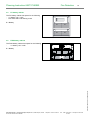
Planning Instruction 66571758GB0
FXL 3NET cabinet
The FXL cabinet has space for the following
- 1 x UI2
- 1 x MC2
- 1 x PS (4,0A)
- Option board (OP) totally 9 pcs:
SLC, max. 4 pcs
CLC, max. 4 pcs
IOC, max. 4 pcs
OCA, max. 4 pcs
MCOX-OB, max. 1 pcs
REPX-OB, max. 1 pcs
ZLPX-IC, max. 1 pcs
3.3
OP
OP
OP
PS
OP
MC2
OP
B
B
FXS 3NET cabinet
The FXS cabinet has space for the following
- 1 x UI2
- 1 x MC
- Option board (OP) totally 1 pcs:
SLC, max. 1 pcs
CLC, max. 1 pcs
IOC, max. 1 pcs
OCA, max. 1 pcs
MCOX-OB, max. 1 pcs
REPX-OB, max. 1 pcs
ZLPX-IC, max. 1 pcs
Note!
MC2
FXM 3NET cabinet
The FXM cabinet has space for the following
- 1 x UI2
- 1 x MC2
- 1 x PS (2,2A)
- 2 x Battery (B) 12V / 12Ah
- Option board (OP) totally 2 pcs:
SLC, max. 2 pcs
CLC, max. 2 pcs
IOC, max. 2 pcs
OCA, max. 2 pcs
MCOX-OB, max. 1 pcs
REPX-OB, max. 1 pcs
ZLPX-IC, max. 1 pcs
3.4
11
MC2
OP
© 2009 Schneider Electric. All rights reserved.
3.2
Fire Detection
The power supply feed has to be brought
from an FX 3NET, FXL 3NET or FXM
3NET panel
Schneider Electric Pelco Finland Oy Kalkkipellontie 6, 02650 Espoo, Finland
Document Number 66571758GB0
Telephone: +358 10 446 511
Fax: +358 10 446 5103
49 2011
www.pelco.com/nordic
Planning Instruction 66571758GB0
3.5
Fire Detection
12
FX battery cabinet
The FX battery cabinet has space for the following
- 4 x battery 12V / 17Ah
- Fire alarm and Fault warning router
B = Battery
3.6
B
B
B
B
FXM battery cabinet
The FXM battery cabinet has space for the following
4 x battery 12V / 12Ah
B = Battery
B
B
© 2009 Schneider Electric. All rights reserved.
B
B
Schneider Electric Pelco Finland Oy Kalkkipellontie 6, 02650 Espoo, Finland
Document Number 66571758GB0
Telephone: +358 10 446 511
Fax: +358 10 446 5103
49 2011
www.pelco.com/nordic
Planning Instruction 66571758GB0
Fire Detection
4.
Mechanical installation
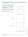
4.1
Installation, FX 3NET and FXL 3NET control panels
13
The mounting surface must be flat and it must bear the
weight of the control panel and the chart file cabinet.
The weight of the control panel excl. batteries is 11 kg
and incl. batteries (2 x 17 Ah) 23 kg. The weight of the
chart file cabinet is 9 kg.
The mounting must be made directly on the wall surface,
without any distance bushings or similar, to ensure IP30
rating.
The weight of the battery cabinet excl. batteries is 7 kg
and incl. batteries (4 x 17 Ah) 31 kg.
FX control panel
Chart cabinet
© 2009 Schneider Electric. All rights reserved.
Battery cabinet
Schneider Electric Pelco Finland Oy Kalkkipellontie 6, 02650 Espoo, Finland
Document Number 66571758GB0
Telephone: +358 10 446 511
Fax: +358 10 446 5103
49 2011
www.pelco.com/nordic
Planning Instruction 66571758GB0
4.2
Fire Detection
14
Installation, FXM 3NET control panel
The mounting surface must be flat and it must bear the
weight of the control panel and the chart file cabinet.
The weight of the control panel exl. batteries is 8 kg and
incl. batteries 20 kg.
42
The weight of the battery cabinet is exl. batteries is 4 kg
and incl. batteries 28 kg.
160
The weight of the chart file cabinet is 9 kg.
181
335
The mounting must be made directly on the wall surface,
without any distance bushings or similar, to ensure IP30
rating.
335
160
FXM control panel
7
370
578
1770
485
1728
169
Battery cabinet
Chart cabinet
1088
370
© 2009 Schneider Electric. All rights reserved.
424
1058
6
Schneider Electric Pelco Finland Oy Kalkkipellontie 6, 02650 Espoo, Finland
Document Number 66571758GB0
Telephone: +358 10 446 511
Fax: +358 10 446 5103
49 2011
www.pelco.com/nordic
Planning Instruction 66571758GB0
4.3
Fire Detection
15
Installation, FXS 3NET control panel
The mounting surface must be flat and it must bear the
weight of the control panel and the chart file cabinet.
The weight of the control panel is 4.4 kg.
The weight of the chart file cabinet is 9 kg.
328
160
40
The mounting must be made directly on the wall surface,
without any distance bushings or similar, to ensure IP30
rating.
32
FXS control panel
© 2009 Schneider Electric. All rights reserved.
1770
1728
1088
1056
576
488
Chart cabinet
Schneider Electric Pelco Finland Oy Kalkkipellontie 6, 02650 Espoo, Finland
Document Number 66571758GB0
Telephone: +358 10 446 511
Fax: +358 10 446 5103
49 2011
www.pelco.com/nordic
Planning Instruction 66571758GB0
5.
Fire Detection
16
FX 3NET, multi-panel networked system
FX 3NET is the solution for fire detection systems that consists of several individual panels and which interact with
each other as if they were one huge panel. Any panel (or all of them) can handle the whole system. The flexibility in
the configuration of the relation between the panels has the benefit of offering the designer the opportunity to
define a system that best suits the needs of the user/owner of the system.
5.1
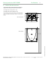
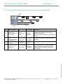
Seeing and visible panels
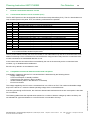
The FX 3NET system is not a traditional hierarchical system with main and sub-panels. In FX 3NET, all the panels
are equal in terms of hardware and software that connects the panels together. This means that they are all able to
monitor and control each other.
For large sites, the configuration of the relation between the panels supports the functional clustering of panels, -for
example, per building, -while still having the possibility of overall control and monitoring from one or several panels.
These clusters can form "intersections", that is, they can have common panels.
The FX 3NET concept is built on the configuration of "seeing" and "visible" panels. Seeing panels ”see” visible
panels, that is, they monitor and control the visible panels.
Panels can also be configured to see each other, that is, they can, at the same time, be both seeing and visible
with respect to each other.
A
B
C
Panel 1
Panel 2
Panel 3
Site: Office house
Seeing panel
Location
1
Entrance A
2
Entrance B
3
Entrance C
Total number of connections
Visible panels
2, 3
1, 3
2, 4
Schneider Electric Pelco Finland Oy Kalkkipellontie 6, 02650 Espoo, Finland
Document Number 66571758GB0
Telephone: +358 10 446 511
Number of
connections
2
2
2
6
Max. 256
Fax: +358 10 446 5103
49 2011
www.pelco.com/nordic
© 2009 Schneider Electric. All rights reserved.
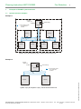
Example 1
A large office building with three FX panels, one at each entrance to the building. A typical configuration would be
that all panels see each other. In this way, no matter which entrance the fire brigade arrives at, they always have
full information for the situation.
Planning Instruction 66571758GB0
Fire Detection
17
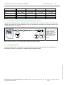
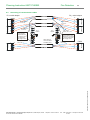
Example 2
Consider an industrial site with two large buildings and a gate building. The gate should see all events to be able to
direct the fire brigade. Each building should have (as in the previous example) mutual monitoring and control
between the panels in the building, but there is no need to see the alarms between the buildings.
The configuration would be that all panels are visible to the gate panel, all panels in the first building are visible to
each other (but not to the panels in the second building) and, finally, all panels in the second building are visible to
each other (but not to the panels in the first building).
Building 2
5
6
7
Building 1
2
3
4
Gate
1
Seeing panel
Location
1
Gate
2
Building 1
3
Building 1
4
Building 1
5
Building 2
6
Building 2
7
Building 2
Total number of connections
Visible panels
2, 3, 4, 5, 6, 7
3, 4
2, 4
2, 3
6,7
5,7
5,6
Schneider Electric Pelco Finland Oy Kalkkipellontie 6, 02650 Espoo, Finland
Document Number 66571758GB0
Telephone: +358 10 446 511
Number of
connections
6
2
2
2
2
2
2
12
Max. 256
Fax: +358 10 446 5103
49 2011
www.pelco.com/nordic
© 2009 Schneider Electric. All rights reserved.
Site: Industrial site
Planning Instruction 66571758GB0
5.2
Fire Detection
18
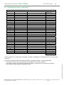
Site plan table of seeing – visible panels
Site:
Seeing panel
Location
Visible panels
Number of
connections
1
2
3
4
5
6
7
8
9
10
11
12
13
14
15
16
17
18
19
20
21
22
23
24
25
26
27
28
29
30
31
32
Total number of connections
Max. 256
The logical connection between the panels is based on configured "seeing" - "visible" relationships.
- Two panels of which one is seeing and the other visible form one logical connection
- Two panels of which both are seeing and visible in relation to each other form two logical connections
- The maximum number of logical connections is 256
Schneider Electric Pelco Finland Oy Kalkkipellontie 6, 02650 Espoo, Finland
Document Number 66571758GB0
Telephone: +358 10 446 511
Fax: +358 10 446 5103
49 2011
www.pelco.com/nordic
© 2009 Schneider Electric. All rights reserved.
Up to 32 panels in any combination of FX 3NET, FXL 3NET, FXM 3NET or FXS 3NET panels can be physically
connected.
Planning Instruction 66571758GB0
5.3
Fire Detection
19
Interpanel communication
In large systems with several panels, and especially if the panels are located apart, it is important to ensure the
communication between the panels. Therefore the FX 3NET communication is secured with two separate
communication lines (System 1 and System 2). If one line is broken or shorted, the system is still able to
communicate with the other one. This redundancy also includes the communication circuitry in the panels. Both
communication lines are constantly monitored and if any faults are detected in either of them, a fault warning is
issued immediately.
The physical connection is based on the RS-485 standard with all panels connected in parallel to each
communication line. The length of the cable can be up to 1,200 m, but, if needed, it can be extended to several
kilometres with base band modems or optical fibre modems.
5.4
Networked FX 3NET main parameters
FX_ 3NET panels in any combinations
Seeing – visible connections
Addressable detection circuits
Detection zones
32
256
255
8,000
Note!
When the INFO serial communication is used, the maximum address capacity per detection circuit is
214: lower address range 1...159 + higher address range 201...255.
Note!
In an FX 3NET system, the FX control panels must be configured before they are connected to each
other.
© 2009 Schneider Electric. All rights reserved.
A standalone FX 3NET system can be commissioned and used without configuration; however, the
following has to be considered:
Every time the system is started, the presence of all addresses has to be verified manually.
The zone assignments of the addresses are according to the default scheme.
Schneider Electric Pelco Finland Oy Kalkkipellontie 6, 02650 Espoo, Finland
Document Number 66571758GB0
Telephone: +358 10 446 511
Fax: +358 10 446 5103
49 2011
www.pelco.com/nordic
Planning Instruction 66571758GB0
Fire Detection
6.
Addressable detection circuits, addresses, zones
6.1
FX-SLC addressable detection circuits and addresses
20
The cables that connect the detectors and the I/O-modules to the panel are called detection circuits (or loops). The
detection circuits are identified by a two-digit number and are by default:
01 … 02
for an FX panel with two detection circuits (one Loop Controller)
01 … 04
for an FX panel with four detection circuits (two Loop Controllers)
01 … 06
for an FX panel with six detection circuits (three Loop Controllers)
01 … 08
for an FX panel with eight detection circuits (four Loop Controllers)
With the configuration software the detection circuit identifications can be changed to any consecutive range of
numbers with a maximum value of 256.
The detectors and the I/O-modules are individually assigned a number (address) during installation and can
therefore be identified by the panel, using a proprietary communication protocol. The address setting in the devices
is simply done with two rotary decimal switches, thus having a range of 1 … 159. In addition, the panel can
distinguish between detector addresses and I/O-module addresses, thus providing a total address capacity per
loop of 001 … 159 and 201 … 359, altogether 318 addresses. For example, a detector with address setting 37 is
handled separately from an I/O-module with the same address setting.
By definition, a control panel that is not configured uses the lower address range (001…159) by default. If the
panel finds a detector and an I/O module with the same address setting, the detector will be assigned the address
from the lower range and the I/O module the address from the higher range (201…359).
Within the system a detector (or I/O-module) is identified by the detection circuit and the setting of the address
switches. This identification is expressed in the FX display as ‘dc.add’, where ‘dc’ is the detection circuit and ‘add’
is the address setting, e.g. 05.037.
Max. 159 detector
addresses and 159 I/O
module addresses in free
order in all loops.
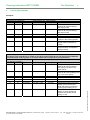
System capacity
System type
Note!
When the INFO serial communication is used, the maximum address capacity per detection circuit is
214: lower address range 1...159 + higher address range 201...255.
Note!
The maximum number of 200 series products in one FX-SLC loop is 20.
Note!
If one or more (max. 20) 200 series products are used in the FX-SLC loop, the max. cable resistance
is 40 Ω.
Schneider Electric Pelco Finland Oy Kalkkipellontie 6, 02650 Espoo, Finland
Document Number 66571758GB0
Telephone: +358 10 446 511
Fax: +358 10 446 5103
49 2011
www.pelco.com/nordic
© 2009 Schneider Electric. All rights reserved.
Detection
Det. addresses System type
Detection
Addresses
circuits
circuits
FX 2
2
318
FX 4
4
512
*
FX 3NET
255
16,384*
FX 6
6
512
*
FX 8
8
512
*
* The maximum number of detectors and manual call points has to be kept as 512 for compliance with the EN54
standard. For other purposes, the full address range of 318 addresses per loop can be used.
Planning Instruction 66571758GB0
6.2
Fire Detection
21
Detection zones
Detectors in a fire detection system are usually grouped into ‘detection zones’. In conventional systems, the
detection circuit coincides with a detection zone, but in addressable systems such as the FX 3NET, the detectors
are grouped by the software. The zones are identified by a four-digit number in the range 0001 … 9999 and they
have to be consecutive within an FX panel.
In a standalone FX 3NET system the addresses are by default assigned to zones according to the following
scheme; however, this assignment can easily be changed with the configuration software. When configured, any
detector within the FX panel, even in different detection circuits, can be assigned to any zone. All addresses have
to be assigned to a zone.
Default assignment of addresses into detection zones:
Addresses
Low range
001 … 016
017 … 032
033 … 048
049 … 064
065 … 080
081 … 096
097 … 112
113 … 128
129 … 144
145 … 159
6.3
High range
201 … 216
217 … 232
233 … 248
249 … 264
265 … 280
281 … 296
297 … 312
313 … 328
329 … 344
345 … 359
1st Loop Controller
L1
L2
1
11
2
12
3
13
4
14
5
15
6
16
7
17
8
18
9
19
10
20
Detection circuits (Loops)
2nd Loop Controller 3rd Loop Controller
L3
L4
L5
L6
21
31
41
51
22
32
42
52
23
33
43
53
24
34
44
54
25
35
45
55
26
36
46
56
27
37
47
57
28
38
48
58
29
39
49
59
30
40
50
60
4th Loop Controller
L7
L8
61
71
62
72
63
73
64
74
65
75
66
76
67
77
68
78
69
79
70
80
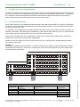
FX-SLC Addressable detection circuit structure
The detection circuit cabling can be arranged in a variety of lay-outs, being flexible for all applications. However,
the following has to be considered when selecting a cable lay-out.
The cable resistance between the panel and any detector may not exceed 60 .
If a large number of sounders, powered from the detection circuit, are used, the maximum resistance may be
further restricted to ensure sufficient voltage to all devices (see section 6.6).
The cable capacitance may not exceed 360 nF.
Not more than one zone (max. 32 detectors and/or manual call points) may drop out of operation in case of a
fault in the cable.
There are limitations on the number of devices between short circuit isolators (see section 6.5).
Use the system capacity calculation tool.
© 2009 Schneider Electric. All rights reserved.
Note!
Schneider Electric Pelco Finland Oy Kalkkipellontie 6, 02650 Espoo, Finland
Document Number 66571758GB0
Telephone: +358 10 446 511
Fax: +358 10 446 5103
49 2011
www.pelco.com/nordic
Planning Instruction 66571758GB0
Fire Detection
22
Closed detection circuit (highly recommended)
A closed detection circuit gives the highest safety because the panel can still communicate with all
addresses even if the cable is cut. To minimise the effect of a short circuit, isolators are available, which
reduces the number of dropped-out addresses to the addresses between the isolators that are closest to the
short circuit. The rule of a max. 60 between a panel and any detector has to be considered even if the
cable is cut at either end of the detection circuit. The cable capacitance in this layout is normally not an issue
of concern.
Closed detection circuit with branches (recommended with reservations)
Branches are allowed if the length of the branch is kept short (< 100 m) and if the number of addresses that
may drop out in case of a cable failure is less than 32. Again, the rule of cable resistance has to be
considered in any case of cable cut. The capacitance may be an issue if there are several branches. Check
with the cable manufacturer and calculate the total capacitance.
Open-end detection circuit (not generally recommended)
Least efficient, since only 32 addresses can be used on the circuit. With that restriction in mind, it can still
provide the longest distance between the panel and the farthest address.
Closed detection circuit
Open-end detection circuit
60 Ω
60 Ω
Closed detection circuit + addressable branches
60 Ω
Note!
When the INFO serial communication is used, the maximum address capacity per detection circuit is
214: lower address range 1...159 + higher address range 201...255.
Note!
The maximum number of 200 series products in one FX-SLC loop is 20.
Note!
If one or more (max. 20) 200 series products are used in the FX-SLC loop the max. cable resistance
is 40 Ω.
Note!
Use the system capacity calculation tool.
Schneider Electric Pelco Finland Oy Kalkkipellontie 6, 02650 Espoo, Finland
Document Number 66571758GB0
Telephone: +358 10 446 511
Fax: +358 10 446 5103
49 2011
www.pelco.com/nordic
© 2009 Schneider Electric. All rights reserved.
60 Ω
Planning Instruction 66571758GB0
6.4
Fire Detection
23
FX control groups
Note!
See the document “Configuration data”.
Note!
See the user manual of the WinFX3Net configuration tool.
The concept of control groups in an FX panel is a way of grouping the various inputs of the panel to facilitate the
activation of outputs. The control groups are defined separately from the detection zones.
‘Control groups’ goes hand in hand with ‘events’. There are two kinds of events: input events and output events.
Input events are the type of signals that the control logic reacts to for example, when a detector gives a fire signal,
we say that the input event is a fire event. Output events are events activated (triggered) by the logic. Certain input
events have corresponding output events for example, a fire input event corresponds to an alarm device output
event.
999 specific control groups, one local (general) control group and one general control group are defined. In this
document, and in the configuration tool, these are identified with the numerical values 1 ... 999 and the words
'Local' and ‘General’, respectively.
In an FX 3NET system, the 999 control groups are split into two ranges: local and shared (over the network). The
split point is by default at 100, meaning that the local control groups are 1 ... 100 and the shared control groups are
101 ... 999. The split point can be changed for each panel with the configuration tool. Input events for the control
groups in the local range are seen only by the panel where the event occurs. Input events for the control groups in
the shared range are seen by all seeing panels.
There are nine different control groups to be defined for a certain input event. The table below describes the main
functional options of control groups.
Control
group
Ctrl A
Ctrl B
For all input event types
For all inputs: panel and addresses
Default split point 100 local/shared
For phased evacuation (6.4.3)
For delayed alarm (6.4.4)
For address fire input
For fire outputs
Default split point 100 local/shared
Delayed outputs (6.4.2)
Delay 0 ... 60 minutes with 1 second step
© 2009 Schneider Electric. All rights reserved.
CG1 + D
CG2 + D
CG3 + D
CG4 + D
CG5 + D
CG6 + D
CG7 + D
Functional options
Schneider Electric Pelco Finland Oy Kalkkipellontie 6, 02650 Espoo, Finland
Document Number 66571758GB0
Telephone: +358 10 446 511
Fax: +358 10 446 5103
49 2011
www.pelco.com/nordic
Planning Instruction 66571758GB0
Fire Detection
24
6.4.1 Control groups for all event types (Ctrl A and Ctrl B)
Control group A and B inputs are not limited to the detectors and other addressable devices in the loop; monitoring
inputs in the panel can also be members of control groups. Control group outputs can also be both addressable
outputs in the loop as well as relay outputs in the panel.
An input event is signalled to both Control A and Control B immediately when the event occurs, except if the device
is set up for delayed alarm. If the input device is set up for delayed alarm the event is signalled to Control A
immediately, and to Control B after the delay.
An output device that is configured as belonging to the ‘General’ control group responds to its corresponding input
event from any input device in any visible panel, regardless of the control group assignments of that input device.
An output device that is configured as belonging to the ‘Local’ control group, responds to its corresponding input
event from any input devices in the same panel, regardless of the control group assignments of that input device.
An output device that is configured to belonging to any one, or combination of specific control groups (1 … 999),
responds to its corresponding input event only from input devices with a matching control group assignment.
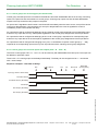
6.4.2 Control groups for fire event inputs and outputs (CG1 + D ... CG7 + D)
The seven control groups CG1 + D ...CG7 + D, can be used only with addressable fire event inputs. The output can
be address or panel fire output.
These “CGn + D” control groups can be delayed individually. The delay can be configured to be 0 --- 60 minutes
with 1 second steps.
Sequence example 1: reset after all delays
Fire
Silence
10s
12s
Re-sound
Reset OK
(normal press)
Input (e.g. MCP in alarm state)
Fire alarm device
Fire alarm device (10s delay)
Fire Output
Fire Output (10s delay)
© 2009 Schneider Electric. All rights reserved.
Fire Output (12s delay)
Schneider Electric Pelco Finland Oy Kalkkipellontie 6, 02650 Espoo, Finland
Document Number 66571758GB0
Telephone: +358 10 446 511
Fax: +358 10 446 5103
49 2011
www.pelco.com/nordic
Planning Instruction 66571758GB0
Fire Detection
25
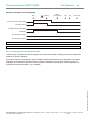
Sequence example 2: reset during delay
Fire
Silence
Reset
(short press)
10s
12s
Re-sound
Input (e.g. MCP in alarm state)
Fire alarm device
Fire alarm device (10s delay)
Fire Output
Fire Output (10s delay)
Fire Output (12s delay)
Note!
“Silence” affects only the fire alarm device outputs.
Note!
The shortest delay is always displayed on the user interface display if more than 1 delay is activated.
6.4.3 Control group use for phased evacuation
Control groups A and B can be used to support a voice alarm fire evacuation strategy in big and/or complicated
buildings or groups of buildings.
© 2009 Schneider Electric. All rights reserved.
There are numerous circumstances in which a staged fire alarm arrangement may be appropriate. One typical
application is a building with phased evacuation. In high-rise buildings, in which those closest to the fire are
evacuated in the first phase, with other areas evacuated in a series of further phases. Another application is a
progressive horizontal evacuation, e.g. in hospitals.
Schneider Electric Pelco Finland Oy Kalkkipellontie 6, 02650 Espoo, Finland
Document Number 66571758GB0
Telephone: +358 10 446 511
Fax: +358 10 446 5103
49 2011
www.pelco.com/nordic
Planning Instruction 66571758GB0
Fire Detection
26
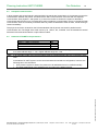
6.4.4 Control group use for delayed alarm
Control groups A and B can be used together with the DAPX alarm panel for a delayed alarm according to the
Swedish standard.
The “delayed alarm” functional principle has been described in the following diagram.
Fire detection
Delay function configurated
Delay function not configurated
Detector
Delayed
function
ON
Call point
Detector
No
Yes
Local alarm
Delay T1<60s
Alarm transmission
delay
Acknowledge
during T1
No
Yes
Delay T1<600s
Alarm transmission
additional delay
Check
during T2
No
Yes
Yes
Call point
Alarm transmission
No
Reset
Note!
More detailed information is found in the WinFMPX and WinFX3Net configuration software instructions.
Note!
A typical application definition is T1 = 60s and T2 = 300s. The total maximum T1 + T2 = 600s.
Note!
The use of the function “delayed alarms” must always be agreed with local authorities.
Schneider Electric Pelco Finland Oy Kalkkipellontie 6, 02650 Espoo, Finland
Document Number 66571758GB0
Telephone: +358 10 446 511
Fax: +358 10 446 5103
49 2011
www.pelco.com/nordic
© 2009 Schneider Electric. All rights reserved.
More help
needed
Planning Instruction 66571758GB0
6.5
Fire Detection
27
Number of devices between short circuit isolators
Using short circuit isolators and returning the detection circuit to the panel, the full capacity of the detection circuit
can be used. Short circuit isolators have to be installed at the boundary of each zone to comply with the
requirement that not more than one zone falls out of operation in the case of a single cable fault.
Note!
6.6
Use the system capacity calculation tool.
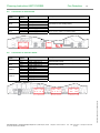
Number of devices in an addressable detection circuit
It is necessary to make careful calculations of load on, and resistance of, the detection circuit, especially if
addressable sounders are installed on the detection circuit. The resistance from the panel to any device has to be
less than 60 and this is to be the case even if there’s one cut anywhere in the detection circuit. It may be
necessary to decrease further the resistance and thus the voltage drop, by using thicker cable, if the alarm load is
high.
Maximum peak current
The current consumption indicated in data sheets and other documentation is the mean value and is good for
battery backup calculation. However, the communication in the detection circuit decreases the duty cycle of the
power supply and therefore the mean values have to be multiplied by 1.33 when calculating the peak current. Thus:
Max. mean current = 350 mA
Max. peak current = 450 mA
A current limiter of 560 mA limits the current in the detection circuit.
Voltage drop calculation
The more symmetrically (with respect to the centre of the cable) the load is distributed, the better with respect to
voltage drop. On the other hand, the more the load is concentrated close to either end of the cable (no matter
which, because the system has to operate even if one end is cut), the worse it is with respect to voltage drop.
The voltage drop can be calculated using the formula:
where
I tot * R tot * a * b
I tot = total current (mean value as indicated in the documentation)
R tot = total resistance
a = correcting factor for duty cycle of power supply
b = correcting factor for load distribution
The detection circuit provides both power supply to the devices and the communication between the panel and the
devices. This communication affects the duty cycle of the power supply and has to be corrected for with a factor of
a = 1.33.
The highest minimum voltage for the addressable devices is 15V (the LEDs of some modules have poor
performance under 17.5 V), and since the loop provides a minimum voltage of 23.5 V, we can use 6 V (including a
safety margin) as the maximum allowed voltage drop in the loop cabling.
Note!
Use the system capacity calculation tool.
Schneider Electric Pelco Finland Oy Kalkkipellontie 6, 02650 Espoo, Finland
Document Number 66571758GB0
Telephone: +358 10 446 511
Fax: +358 10 446 5103
49 2011
www.pelco.com/nordic
© 2009 Schneider Electric. All rights reserved.
With a perfectly symmetrical distribution of the load, the voltage drop is only half (b = 0,5) compared with total load
being at either end (b = 1). A generally safe value to use is b = 0.85, which corresponds to an evenly distributed
load over half of the cable (0.75) + a safety margin of 0.1.
Planning Instruction 66571758GB0
7.
FX-CLC Conventional detection circuits
7.1
Conventional detection circuit controller (CLC)
Fire Detection
28
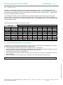
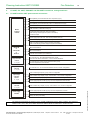
The FX 3NET panels can also be equipped with Conventional Loop Controllers (CLC). The CLC board takes one
loop controller place in the panel. Thus, the following combinations are possible:
LCs
0
1
2
3
4
Note!
CLCs
1
2
3
4
0
1
2
3
0
1
2
0
1
0
Comment
No addressable loops, 1 to 16 conventional lines
No addressable loops, 17 to 32 conventional lines
No addressable loops, 33 to 48 conventional lines
No addressable loops, 49 to 64 conventional lines
2 addressable loops (each 159 + 159 addresses), 0 conventional lines
2 addressable loops (each 159 + 159 addresses), 1 to 16 conventional lines
2 addressable loops (each 159 + 159 addresses), 17 to 32 conventional lines
2 addressable loops (each 159 + 159 addresses), 33 to 48 conventional lines
4 addressable loops (each 159 + 159 addresses), 0 conventional lines
4 addressable loops (each 159 + 159 addresses), 1 to 16 conventional lines
4 addressable loops (each 159 + 159 addresses), 17 to 32 conventional lines
6 addressable loops (each 159 + 159 addresses), 0 conventional lines
6 addressable loops (each 159 + 159 addresses), 1 to 16 conventional lines
8 addressable loops (each 159 + 159 addresses), 0 conventional lines
The total number of detectors and manual call points, connected to one FX panel, may not exceed
512, to fulfill the EN54 standard requirements.
The FX panel handles internally the whole CLC board as one addressable loop and each conventional line as an
address of that loop. Each conventional line can therefore be configured and used just as the conventional zone
module connected to an addressable detection circuit.
It also means that the conventional lines are handled by the user in the same way as the conventional zone
modules, e.g. for disablement/re-enablement.
Each line is by default in its own detection zone.
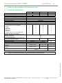
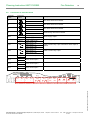
7.2
Compatible conventional detectors and manual call points
Compatibility of detectors with the CLC conventional line is determined by the following factors:
Supply voltage range
Current consumption in standby condition
Voltage across the detector in alarm condition
Series resistance (either in the detector or in the base)
End-of-Line resistor
If the line goes through an Exi barrier, the maximum allowed cable resistance and current consumption is less than
for a normal line.
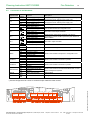
The following table shows the required series resistor for a number of detector voltages (in alarm condition), the
two allowed EOL types and whether or not an Exi barrier is connected to the loop.
Schneider Electric Pelco Finland Oy Kalkkipellontie 6, 02650 Espoo, Finland
Document Number 66571758GB0
Telephone: +358 10 446 511
Fax: +358 10 446 5103
49 2011
www.pelco.com/nordic
© 2009 Schneider Electric. All rights reserved.
The voltage supplied by the CLC to the conventional line is 21 VDC to 24 VDC. The maximum allowable voltage
drop in the cable is 21 V minus the lowest operating voltage of the connected devices.
Planning Instruction 66571758GB0
EOL resistor, Exi
Max cable resistance
Max detector load
8V
5V
3V
1V
0V
7.3
4k7, 5%, not Exi
100Ω
1,8 mA
50 – 1000Ω
110 - 1300Ω
140 - 1500Ω
180 - 1700Ω
200 - 1800Ω
Fire Detection
2k94, 1%, not Exi
100Ω
4,0 mA
50 - 550Ω
110 - 750Ω
150 - 880Ω
190 - 1010Ω
210 - 1070Ω
4k7, 5%, Exi
50Ω
1,5 mA
10 - 700Ω
150 - 1050Ω
250 - 1250Ω
340 - 1500Ω
390 - 1600Ω
29
2k94, 1%, Exi
50Ω
3,0 mA
10 - 320Ω
170 - 550Ω
280 - 710Ω
380 - 880Ω
440 - 960Ω
Conventional detection circuit structure and End-of-Line resistors
Each line (conventional detection circuit) of the CLC is terminated with an End-of-Line resistor. The value of this
resistor can be either 4k7 or 2k94, depending on the type of detectors connected to the line and the alarm series
resistor the detector or its base has.
Max 32 detectors and
manual call points
together. The number
may be reduced
further by the current
consumption of the
devices.
See the table in section 7.2 for required series resistors and EOL resistors.
7.4
Configurable options
© 2009 Schneider Electric. All rights reserved.
For different applications, the operation of the conventional line can be modified through the configuration tool
WinFX 3NET. See the document 6657 1783GBx FX3Net Configuration Data.
Schneider Electric Pelco Finland Oy Kalkkipellontie 6, 02650 Espoo, Finland
Document Number 66571758GB0
Telephone: +358 10 446 511
Fax: +358 10 446 5103
49 2011
www.pelco.com/nordic
Planning Instruction 66571758GB0
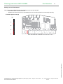
8.
Cabling
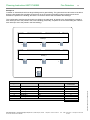
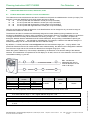
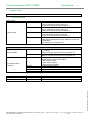
8.1
Cables of addressable detection circuit
Fire Detection
30
1
5
3
FX_
4 5
6
3
7
2
8
10
9
x10
4 5
3
6
7
2
8
10
9
3
2
1
C
4 5
0
6
7
8
9
x10
4
4 5
3
6
7
2
8
10
9
C
4 5
3
6
7
2
10 98
x10
4 5
3
6
7
2
8
10
9
4 5
6
3
7
2
10 98
x10
C
6
4 5
6
3
7
2
10 98
C
7
2
Cable connection
1
Addressable
detection circuit
cables
2
Sub-detection
circuits of
conventional zone
modules
3
Power supply to
conventional zone
modules
4
5
6
7
Addressable
control modules
- alarm line
- power supply
Addressable
monitor modules
- monitor lines
Addressable
control modules
Conductors x
area
2 x 0.5 mm2 +
shield
2 x 1.0 mm2 +
shield
2 x 0.5 mm2 +
shield
Max. length
Comments
810 m
(60 )
1600 m
(60 )
1200 m
(100 )
The cable resistance of the loop is max. 60
and the capacitance max. 180 nF between
conductor and shield, 360 nF between
conductors. Max. voltage drop is 6V.
Conventional zone module EM210E-CZ and
300 series conventional detectors or
conventional manual call points.
2 x 0.5 mm2 +
shield
2 x 1.0 mm2 +
shield
2 x 0.5 mm2 or
2 x 1.5 mm2 or
2 x 2.5 mm2
625 m
(50 )
1200 m
(50 )
To be
calculated
separately
Cable resistance max. 50
2 x 0.5 mm2 +
shield
1200 m
(100 )
2 x 0.5 mm2 or
2 x 1.5 mm2 or
2 x 2.5 mm2
To be
calculated
separately
Schneider Electric Pelco Finland Oy Kalkkipellontie 6, 02650 Espoo, Finland
Document Number 66571758GB0
Control modules EM201E and EM221E.
Number and distances of the relay control
modules define the conductor area and
length of the power supply cable.
Monitor modules EM210E, EM220E, EM221.
The equipment receiving the contact signal
may have restrictions on cable properties.
Load controlled by the relay output may
restrict allowed resistance and length per
cross section.
Telephone: +358 10 446 511
Fax: +358 10 446 5103
49 2011
www.pelco.com/nordic
© 2009 Schneider Electric. All rights reserved.
No
Planning Instruction 66571758GB0
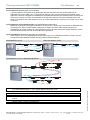
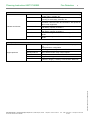
8.2
Fire Detection
31
Cables of conventional detection circuits CLC, alarm device lines, input/output lines
8
9
10
11
FX_
No
8
9
10
Conventional
detection circuits of
a CLC board
FX alarm device
lines
- fire bell, siren line
- fault buzzer line
FX clean contact
input lines
FX clean contact
output lines
Conductors x
area
2 x 0.5 mm2 +
shield
2 x 1.0 mm2 +
shield
Max. length
Comments
1200 m
(100 )
2400 m
(100 )
The cable resistance of the loop is max. 50 ,
if an Exi barrier is connected to the loop,
otherwise max 100 .
The max. allowed capacitance of the cable is
0.5 µF.
2 x 0.5 mm2 or
2 x 1.0 mm2 or
2 x 2.5 mm2
To be
calculated
separately
2 x 0.5 mm2
2000 m
2
2 x 0.5 mm or
2 x 1.0 mm2
To be
calculated
separately
Max. allowed voltage drop defines cable to
be used.
The equipment receiving the contact signal
may have restrictions on cable properties.
Load controlled by the relay output may
restrict allowed resistance and length per
cross section.
© 2009 Schneider Electric. All rights reserved.
11
Cable connection
Schneider Electric Pelco Finland Oy Kalkkipellontie 6, 02650 Espoo, Finland
Document Number 66571758GB0
Telephone: +358 10 446 511
Fax: +358 10 446 5103
49 2011
www.pelco.com/nordic
Planning Instruction 66571758GB0
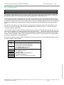
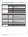
8.3
Fire Detection
32
Cables of serial communication lines and power supply
DAPX
13
FX_
15
18
16
12
MCOX
13
FX_
18
16
13
REPX
18
13
FMPX
18
12
14
17
FXS
12
12
17
13
18
Cable connection
Serial connection
- other FX panels
- System 1 and
System 2
Serial connections
and power supply to FXS
- System 1 and System 2
(RS285)
- Operating voltage 2 pcs
(21…30 VDC)
Serial connections
and power supply
- INFO (RS485)
Conductors x
area
Max. length
Comments
3 x 0.5 mm2 +
shield or
3 x 0.5 mm2
1000 m
RS485
To be calculated
separately
RS485
Operating voltage range 21...30
VDC
5 x 0,5 mm2 +
shield
**)
7 x 0.5 mm2 +
shield
Operating voltage 2 pcs
14
Serial connection
15
Printer connection
- Serial data
Mains supply cable
RS485
Operating voltage range 21...30
VDC
***)
(21…30 VDC)
16
To be calculated
separately
2
2 x 2x0.5 mm +
shield
2 x 2 x 0.5 mm2 +
shield
3 x 1.5 mm2
15 m
RS232
15 m
RS232
Mains connection:
- 230 ±10% VAC, 50-60 Hz
- maximum power 160 VA
(FX and FXL)
- maximum power 80 VA (FXM)
- own circuit fuse 10 A
*) For longer distances see Part 3: Additional Information
**) Communication and power supply in the same cable. Doubled wires.
***) Communication and power supply (2 pcs) in the same cable. Doubled wires.
Schneider Electric Pelco Finland Oy Kalkkipellontie 6, 02650 Espoo, Finland
Document Number 66571758GB0
Telephone: +358 10 446 511
Fax: +358 10 446 5103
49 2011
www.pelco.com/nordic
© 2009 Schneider Electric. All rights reserved.
No
Planning Instruction 66571758GB0
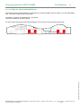
8.4
Fire Detection
Grounding of communication cables
TR+
TRTR+ GND
2a
2b, Spare wire,
not in use
2b, Spare wire,
not in use
1a
1a
1b
2a
FX x
chassis
FX y
chassis
FMPX
2a
1a
© 2009 Schneider Electric. All rights reserved.
1b
1a
TR+
1b
RS485
GND
2b, Spare wire,
not in use
TR-
TR-
Cable shield is
connected ONLY
in FXNET panel
All serial
communication cable
shields are connected
to the grounding filter.
Max length 10mm
GND
2a
2b, Spare wire,
not in use
2a
2b, Spare
wire, not in use
GND
2b, Spare wire,
not in use
TR-
1b
All serial
communication
cable shields are
connected to the
grounding filter.
Max length 10mm
TR+
2a
GND TR+
TR-
1b
1b
SYSTEM 1 SYSTEM 2
1a
1a
TR-
GND
FX y serial adapter
TR+
SYSTEM 2 SYSTEM 1
FX x serial adapter
RS485
33
Schneider Electric Pelco Finland Oy Kalkkipellontie 6, 02650 Espoo, Finland
Document Number 66571758GB0
Telephone: +358 10 446 511
Fax: +358 10 446 5103
49 2011
www.pelco.com/nordic
Planning Instruction 66571758GB0
8.5
Fire Detection
34
Battery backup calculation
The formula for calculating the required battery capacity is:
(L1 x T1 + L2 x T2) x 1.25 [Ah]
where
L1 = standby current in amperes
T1 = standby time in hours
L2 = alarm current in amperes
T2 = alarm time in hours
1.25 = compensation for ageing
The requirements for standby time and alarm time varies in various countries, but if no national requirements exist,
it is recommended to use T1 = 72 hours and T2 = 0.5 hours.
The standby time may be reduced to 30 h under conditions that ensure repair of a broken power
supply and/or main supply within 24 h. Refer to EN54 part 14.
Note!
A 51 Ah battery requires 2 A charging current to be recharged according to EN54 part 4 (80% within
24 h and 100% within an additional 48 h).
Note!
National and/or local regulations may require different standby, alarm and recharging times.
Note!
Use the system capacity calculation tool.
© 2009 Schneider Electric. All rights reserved.
Note!
Schneider Electric Pelco Finland Oy Kalkkipellontie 6, 02650 Espoo, Finland
Document Number 66571758GB0
Telephone: +358 10 446 511
Fax: +358 10 446 5103
49 2011
www.pelco.com/nordic
Planning Instruction 66571758GB0
Fire Detection
9.
FX 3NET, FXL 3NET, FXM 3NET and FXS 3NET Technical data
9.1
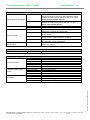
Technical data, standard panels
Dimensions (h*w*d) [mm]
Weight (fully equipped, excl. batteries)
IP Rating
Operating ambient temperature
Storage ambient temperature
Maximum ambient humidity
Backframe material
Cover material
Cover colour
Number of SLC, CLC, IOC and OCA boards
- FX-SLC and/or FX-CLC together
- FX-IOC
- FX-OCA
- REPX-OB
- MCOX-OB
- ZLPX-IC
- FX-SLC, FX-CLC, FX-IOC, REPX-OB,
MCOX-OB, ZLPX-IC together
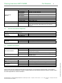
Number of addresses per detection circuit
Detector addresses
IO-module addresses
Total number of detectors and manual call
points connected to the panel
Mains supply voltage
Mains supply power
Operating voltage range
Maximum current consumption in standby
condition
Maximum current consumption in alarm
condition
FX 3NET
FXL 3NET
578 x 425 x 130
11 kg
12 kg
FXM 3NET
328 x 425 x 130
6 kg
IP30
+5…+40°C
0…+50°C
95% RH
sheet steel
plastic
bluish grey
35
FXS 3NET
328 x 417x79
4.4 kg
4
4
4
1
1
1
4
4
4
1
1
1
2
2
2
1
1
1
1
1
1
1
1
1
5
9
2
1
512
396
159
159
512
230 VAC ±10% / 50 ... 60Hz
160 VA
80 VA
21 ... 30 Vdc
NA
1.0 A @ 24 Vdc
0.5 A @ 24 Vdc 0.5 A @ 24 Vdc
4.0 A @ 24 Vdc
2.2 A @ 24 Vdc
Applied standard
1 A @ 24 Vdc
EN54-2
EN54-4
EN54-2
© 2009 Schneider Electric. All rights reserved.
Note! FXS 3NET requires a power feed from an FX 3NET, FXL 3NET or FXM 3NET panel. Available
power from that panel may restrict the current consumption of the FXS panel.
Schneider Electric Pelco Finland Oy Kalkkipellontie 6, 02650 Espoo, Finland
Document Number 66571758GB0
Telephone: +358 10 446 511
Fax: +358 10 446 5103
49 2011
www.pelco.com/nordic
Planning Instruction 66571759GB0
49/2012
Fire Detection
FX 3NET + SLC FIRE ALARM SYSTEM
Part 2: System Devices
These are the planning instructions for an FX 3NET fire detection and alarm system
consisting of
FX 3NET, FXL 3NET, FXM 3NET and FXS 3NET control panels
SLC compatible intelligent field devices
In this document FX refers to all FX 3NET, FXL 3NET, FXM 3NET and FXS 3NET panels. For
information specifically related to a specific panel model, that model type is indicated.
We reserve the right to make technical changes without notice.
The planning instructions consist of 3 parts:
Part 1: General Rules 6657 1758GBx
Part 2: System Devices 6657 1759GBx
Part 3: Additional Information 6657 1760GBx
See also the following instructions:
User guide of the WinFX3Net Configuration Tool 6657 1782GBx
FX3Net Configuration Data 6657 1783GBx
FX3Net System Capacity Calculation Tool 6657 1746GBx
Note!
Instructions given by local authorities must be followed when planning the system.
Planning Instruction 66571759GB0
Fire Detection
2
Contents
© 2009 Schneider Electric. All rights reserved.
1. System devices .................................................................................................................................................. 3 Control equipment ..................................................................................................................................... 3 1.1 Intelligent/addressable AP200 series devices ........................................................................................ 5 1.2 Intelligent/addressable 200 series devices ............................................................................................. 7 1.3 Conventional components ........................................................................................................................ 7 1.4 Exi-area conventional components ......................................................................................................... 8 1.5 Installation accessories ............................................................................................................................ 8 1.6 Schneider Electric Pelco Finland Oy Kalkkipellontie 6, 02650 Espoo, Finland
Document Number 66571759GB0
Telephone: +358 10 446 511
Fax: +358 10 446 5103
49 2011
www.pelco.com/nordic
Planning Instruction 66571759GB0
1.
Fire Detection
3
System devices
Note!
Technical information for the devices can be found in the data sheets.
1.1
Control equipment
Basic panels
FX 3NET
FXL 3NET
Control panels
FXM 3NET
FXS 3NET
Basic control panel without detection circuits. Expandable
to max. 8 detection circuits in steps of 2.
Number of card slots for option boards is 5.
Basic control panel without detection circuits. Expandable
to max. 8 detection circuits in steps of 2.
Number of card slots for option boards is 9
Basic control panel without detection circuits. Expandable
to max 4 detection circuits in steps of 2.
Number of card slots for option boards is 2.
User interface panel without detection circuits and built-in
power supply. Needs power supply feed from an FX, FXL
or FXM panel.
One card slot for an option board.
Card slot option boards
FX-SLC
FX-OCA
REPX-OB
MCOX-OB
ZLPX-IC
Addressable loop controller: expansion 2 - > 4 or 4 - > 6 or
6 - > 8 loops
Maximum number of SLCs and CLCs together is 4
Expansion with 16 conventional loops.
Maximum number of SLCs and CLCs together is 4
For clean contact input monitoring, clean contact control
outputs and alarm device line outputs:
4 clean contact inputs
2 clean contact outputs
4 alarm device line outputs
16 clean contact outputs
Protocol repeater
Logical control unit
Zone Led Control Unit
FX-LB32
FX-LB80
32 LED indications
80 LED indications
Loop controllers
FX-CLC
FX-IOC
Input and/or Output
controllers
© 2009 Schneider Electric. All rights reserved.
UI2 option boards
Panel display unit
Zone display unit
Schneider Electric Pelco Finland Oy Kalkkipellontie 6, 02650 Espoo, Finland
Document Number 66571759GB0
Telephone: +358 10 446 511
Fax: +358 10 446 5103
49 2011
www.pelco.com/nordic
Planning Instruction 66571759GB0
Fire Detection
4
Cabinet and frames
FX-CAB
FXM-CAB
FX-MAP
Cabinets and frames
AX/FX/IX-BAT
FXM-BAT
FX-RMFW
FXM-RMFW
Mounting cabinet. FX control panel sized box for mounting
of extra relays, modules, etc.
Mounting cabinet. FXM control panel sized box for
mounting of extra relays, modules, etc.
Mounting cabinet. FX control panel sized box for
orientation charts and other documentation. Also space for
alarm router equipment.
Battery cabinet. Space for 4 x 17 Ah/12 V batteries.
Total battery capacity 34 Ah/24 V.
Battery cabinet. Space for 4 x 12 Ah/12 V batteries.
Total battery capacity 24 Ah/24 V.
Recess mounting frame. For flush mounting of FX and FXL
panels.
Recess mounting frame. For flush mounting of FXM
panels.
Other system products
FMPX
© 2009 Schneider Electric. All rights reserved.
Support products
DAPX
ZLPX+
optional products
REPX
MCOX
CODINET
Operating unit for fire brigade or information display/INFOline.
Displayed zones configurable.
Operating unit for delayed alarms/INFO-line
Zone LED panel/INFO-line
Open collector and/or relay control outputs
For duplication of the RS485/INFO-line.
Programmable logic controller/INFO-line.
Modem adapter. Used together with short distance
modems in longer (> 1000 m) communication distances.
Schneider Electric Pelco Finland Oy Kalkkipellontie 6, 02650 Espoo, Finland
Document Number 66571759GB0
Telephone: +358 10 446 511
Fax: +358 10 446 5103
49 2011
www.pelco.com/nordic
Planning Instruction 66571759GB0
1.2
Fire Detection
5
Intelligent/addressable AP200 series devices
Intelligent AP200 series detectors for mounting in base B501AP
ESMI 2251CTLE-W 4 sensor fire detector: CO, photo, thermal, IR
ESMI 22051TLE
3 sensor fire detector: photo, thermal, IR
ESMI 22051TLEI
3 sensor fire detector with isolator: photo, thermal, IR
Multi-criteria detectors
ESMI 22051TE
Photo-thermal detector
EN54-7/2001
EN54-5/2001 class A1R
ESMI 22051TEI
Photo-thermal detector with isolator
ESMI 22051E
Optical smoke detector
Optical smoke detectors
ESMI 22051EI
Optical smoke detector with isolator
ESMI 52051E
Heat detector class A1S
ESMI 52051EI
Heat detector class A1S with isolator
ESMI 52051RE
Rate-of-rise detector class A1R
Heat detectors
ESMI 52051REI
Rate-of-rise detector class A1R with isolator
ESMI 52051HTE
High temperature heat detector class BS
ESMI 52051HTEI
High temperature heat detector class BS with isolator
Installation bases for intelligent / addressable detectors
Installation base
B501AP
Relay base
B524RTE-W
Includes a relay output with a single pole switch over
contact
Heater base
B524HTR-W
To prevent condensation in the detector by keeping the
temperature at 5 °C above ambient.
Needs an external 24V power supply and a thermostat.
The intelligent Exi - area smoke detector is mounted in a B501AP base and connected to the addressable loop
through the adapter unit IST-200 and barrier unit Y72221.
Smoke detector
22051EISE
Optical smoke detector EEx ia IIC T5
Note. Only to be used together with the IST-200 and
Y72221 units
Adapter unit
IST-200
A max. of 15 2251EISE detectors can be connected to the
adapter unit and the barrier
Barrier unit
Y72221
EEx ia IIC
MCP5A
SR1T2G
WCP5A
Can be mounted in device box as it is
Surface mounting box
IP67, surface mounting
© 2009 Schneider Electric. All rights reserved.
Manual call points
Call points
Schneider Electric Pelco Finland Oy Kalkkipellontie 6, 02650 Espoo, Finland
Document Number 66571759GB0
Telephone: +358 10 446 511
Fax: +358 10 446 5103
49 2011
www.pelco.com/nordic
Planning Instruction 66571759GB0
Fire Detection
6
Addressable I/O modules
EM210E-CZ
Conventional zone modules
EM210E-CZR
Monitor modules
EM210E
EM220E
EM201E
EM201E-240
Control modules
EM201E-240-DIN
B524RTE-W
Combined monitor and
control module
Special detectors
Duct detector housing
EM221E
DNRE
Address module for standard conventional detectors and
manual call points as well as for beam detectors, flame
detectors and other special detectors. EOL-unit = 50µF.
Cannot be used with Exi barriers.
Address module for intrinsically safe conventional
detectors and manual call points. EOL unit = 3.9kΩ.
Can be used with Exi barriers.
Address module with one contact input.
Address module with two contact inputs.
Address module with one relay output, selectable for
voltage free or voltage carrying function.
Address module with one relay output, for controlling
240Vac circuits.
Address module with one relay output, for controlling
240Vac circuits. To be mounted on a DIN rail.
Detector base equipped with a relay through which a zero
potential output can be established.
Address module with two contact inputs and one clean
contact relay output.
To be used with an intelligent AP200 smoke detector
© 2009 Schneider Electric. All rights reserved.
Addressable, intelligent alarm devices for mounting in base LPSW or SDBW (surface mounting)
WMSOU-RR-P35
Sounder
WMSOU-RR-P36
Sounder with isolator
WMSST-RR-P35
Sounder beacon
Wall mount devices
WMSST-RR-P36
Sounder beacon with isolator
WMSTR-RR-P35
Beacon
WMSTR-RR-P36
Beacon with isolator
IBSOU-PW-P35
Sounder
Integrated detector base
IBSOU-PW-P36
Sounder with isolation
devices
IBSST-PR-P35
Sounder beacon
IBSST-PR-P36
Sounder beacon with isolator
LPBW
Mounting base
SDBW
Deep mounting base
Accessories
WDBR
Waterproof mounting base
DBSPW
Spacer ring
Schneider Electric Pelco Finland Oy Kalkkipellontie 6, 02650 Espoo, Finland
Document Number 66571759GB0
Telephone: +358 10 446 511
Fax: +358 10 446 5103
49 2011
www.pelco.com/nordic
Planning Instruction 66571759GB0
1.3
Fire Detection
7
Intelligent/addressable 200 series devices
Note! The following devices can be used in the FX-SLC detection circuit but the maximum number of these
devices per loop is 20. The maximum detection circuit cable resistance is 40 Ω.
Intelligent high sensitive smoke detectors
LZR-1M
Laser smoke detectors
7251
Intelligent detectors for special applications
EB6500
Beam detector
EB6500S
1.4
High-sensitive smoke detector
High sensitive smoke detector
Intelligent infrared beam detector and reflector providing
for supervision of up to 1400 m2.
Contains short circuit isolator.
Contains a built-in test function.
Conventional components
Detectors for mounting in base B401R (for recessed cabling) and B401DGR (for surface cabling) and for
connection to a EM210E-CZ or EM210E-CZR conventional zone module
Multi-criteria detector
ED 2351TEM
Photo-thermal detector
ED 2351E
Optical smoke detector
Smoke detectors
ESMI 2151E
Optical smoke detector
ED 5351E
Heat detector class A1R
ED 4351E
Heat detector class BS
Heat detectors
4451E
Heat detector grade 1
5451E
Rate-of-rise detector class 1
Manual call points for connection to a EM210CZ
MCP1A
Conventional call points
SR1T-2G
WCP1A
Flush mounting in device box
Surface mounting box SR2G
Waterproof IP67 for surface mounting
Special detectors
EB6500R
EB6500RS
To be connected to the system through conventional zone
module EM210E-CZ
© 2009 Schneider Electric. All rights reserved.
Beam detectors
Schneider Electric Pelco Finland Oy Kalkkipellontie 6, 02650 Espoo, Finland
Document Number 66571759GB0
Telephone: +358 10 446 511
Fax: +358 10 446 5103
49 2011
www.pelco.com/nordic
Planning Instruction 66571759GB0
Fire Detection
8
Alarm devices, beacons and alarm indication panels
MBF-6EV
Bell for indoor use
MBA-6+BBX4
Bell for outdoor use, IP57
EMA1224B4R
Sounder, for wall mounting
EMA1224FR
DBS1224B4W
Sounder, for mounting beneath the detector base
Alarm devices,
DBS1224FW
Beacons
EMA24FRSSR
Sounder/beacon
EMA24RS2R
Beacon, for indoor use
XB-713111/1W
Beacon, IP65, 1W
XB-713311/3W
Beacon, IP65, 3W
Alarm indication panels
LEDFF01
Indicators for fire alarm and fault warning
Remote indicator
NLY-91200
Surface mounting
To be used with both addressable and conventional
detectors
1.5
Exi-area conventional components
Detectors for mounting in socket B401 and B401DG and to be connected to the sub detection circuit of
EM210E-CZR through EXB-2000/P+F
1151EISE
Ionisation detector
Detectors
5451EISE
Rate-of-rise detector, class 1
Barrier unit
EXB-2000/P+F
Manual call points to be connected to the sub detection circuit of EM210E-CZR through EXB-2000/P+F
MCP3 IS
Ex II 1 G, EEx ia II T4, IP24D
Call points
WCP3 IS
Ex II 1 G, EEx ia II T4, IP67
1.6
Installation accessories
End-of-line resistors and End-of-line capacitors
End-of-line resistors
End-of-line capacitor
Base mounting boxes
Mounting box for damp
sites
Lowered ceilings
Base gasket
Surface mount adaptor kit
WB-1AP
Mounting box for damp sites for base B501AP
RMK400AP
MS2000
MS2001
SMK400EAP
Flush mounting box for lowered ceilings for base B501AP
For base B501AP, B401R, B401DGR, B401 and B401DG
For base B524IEFT-1, B524RTE-W
Pelco Finland Oy also supplies special detectors and devices, not mentioned in this document, such as flame
detectors, linear type heat detection systems, wireless detectors and aspiration detection systems. Please contact
the sales department for further information.
Schneider Electric Pelco Finland Oy Kalkkipellontie 6, 02650 Espoo, Finland
Document Number 66571759GB0
Telephone: +358 10 446 511
Fax: +358 10 446 5103
49 2011
www.pelco.com/nordic
© 2009 Schneider Electric. All rights reserved.
4.7 k ± 5%, 0.5 W for alarm device lines
3.9 k ± 5%, 0.5 W for the sub-detection circuit of
EM210E-CZR modules
47 k ± 5%, 0.5 W, EOL resistor for monitoring modules.
EOL capacitor for the sub detection circuit of EM210E-CZ
modules, 50 µF.
Planning Instruction 66571760GB0
49/2011
Fire Detection
FX 3NET + SLC FIRE ALARM SYSTEM
Part 3: Additional Information
These are the planning instructions for an FX 3NET fire detection and alarm system
consisting of
FX 3NET, FXL 3NET, FXM 3NET and FXS 3NET control panels
SLC compatible intelligent field devices
In this document FX refers to all FX 3NET, FXL 3NET, FXM 3NET and FXS 3NET panels. For
information specifically related to a specific panel model, that model type is indicated.
We reserve the right to make technical changes without notice.
The planning instructions consist of 3 parts:
Part 1: General Rules 6657 1758GBx
Part 2: System Devices 6657 1759GBx
Part 3: Additional Information 6657 1760GBx
See also the following instructions:
User guide of the WinFX3Net Configuration Tool 6657 1782GBx
FX3Net Configuration Data 6657 1783GBx
FX3Net System Capacity Calculation Tool 6657 1746GBx
Note!
Instructions given by local authorities must be followed when planning the system.
Planning Instruction 66571760GB0
Fire Detection
2
Contents
© 2009 Schneider Electric. All rights reserved.
1. Examples of FX 3NET system structure .......................................................................................................... 3 System structure examples ...................................................................................................................... 3 1.1 Cable length of a segment ........................................................................................................................ 6 1.2 2. Control group examples ................................................................................................................................... 7 3. Special features to avoid nuisance alarms ..................................................................................................... 8 Day mode .................................................................................................................................................... 8 3.1 Delayed alarm............................................................................................................................................. 8 3.2 Delayed signal inputs ................................................................................................................................ 9 3.3 4. FX 3NET, FXL 3NET, FXM 3NET and FXS 3NET connections, settings and fuses ................................... 10 FX 3NET and FXL 3NET panel external connections ........................................................................... 10 4.1 FXM 3NET panel external connections.................................................................................................. 11 4.2 FXS 3NET panel external connections .................................................................................................. 12 4.3 Connectors on the MC2 board ............................................................................................................... 13 4.4 Connectors on the PS board .................................................................................................................. 14 4.5 Connectors on each SLC board ............................................................................................................. 14 4.6 Connectors on each CLC board ............................................................................................................. 15 4.7 Connectors on each OCA board ............................................................................................................ 15 4.8 Connectors on each IOC board .............................................................................................................. 16 4.9 4.10 FX 3NET, FXL 3NET and FXM 3NET Fuses ........................................................................................... 17 4.11 FX 3NET, FXL 3NET and FXM 3NET Battery backup............................................................................ 18 5. FX Settings and configuration........................................................................................................................ 19 Settings in the FX panel .......................................................................................................................... 19 5.1 Schneider Electric Pelco Finland Oy Kalkkipellontie 6, 02650 Espoo, Finland
Document Number 66571760GB0
Telephone: +358 10 446 511
Fax: +358 10 446 5103
49 2011
www.pelco.com/nordic
Planning Instruction 66571760GB0
1.
Examples of FX 3NET system structure
1.1
System structure examples
Fire Detection
3
Example 1
FX-LB32
- display unit
FX_
FRE
“Seeing”
= Communication cable
- one twisted pair
- shielded
Building 1
Fire Routing
Building 2
FX_
FX_
“Seeing”
“Seeing”
S1
S1
S2
S1
S2
S1
S2
“Visible”
FX_
S1
S2
“Visible”
S1
S2
“Visible”
FX_
“Visible”
FX_
FX_
System 1(S1) and System 2 (S2) = serial communication line
Example 2
FX-LB32
- display unit
FX_
Fire Routing
FRE
“Seeing”
S1
= Communication cable
- one twisted pair
- shielded
S2
S1
S2
FX_
“Visible”
FX_
© 2009 Schneider Electric. All rights reserved.
“Visible”
System 1(S1) and System 2 (S2) = serial communication line
Schneider Electric Pelco Finland Oy Kalkkipellontie 6, 02650 Espoo, Finland
Document Number 66571760GB0
Telephone: +358 10 446 511
Fax: +358 10 446 5103
49 2011
www.pelco.com/nordic
Planning Instruction 66571760GB0
Fire Detection
4
Example 3: FX 3NET communication segments, long distances
S1
Segment 0
Max. 1000 m
S2
FX_
C
C
M
M
FX_
Max. 5 km *)
FX_
Root
Segment 1
FX_
M
M
C
C
FX_
S1
Max. 1000 m
S2
C
C
C
C
M
M
M
M
M
M
C
C
FX_
FX_
S1
Segment 2
Max. 1000 m
S2
FX_
Modem Link
Max. 5 km *)
FX_
FX_
M
M
C
C
FX_
S1
Segment n
Max. 1000 m
S2
C = CODINET (Modem Adaptor)
M = Modem
Modem Link = 2 x Modems + 2 x CODINET
Maximum number of Modem Links in series between 2 FX_ panels is 2.
Note!
Also Modem Links must be doubled.
© 2009 Schneider Electric. All rights reserved.
Note!
*) According to modem specification
Schneider Electric Pelco Finland Oy Kalkkipellontie 6, 02650 Espoo, Finland
Document Number 66571760GB0
Telephone: +358 10 446 511
Fax: +358 10 446 5103
49 2011
www.pelco.com/nordic
Planning Instruction 66571760GB0
Fire Detection
5
Example 4: Factory area
FX_
S1
Segment 3
FX_
S2
ML
S1
ML
Segme nt 2
S2
FX_
FR E
FX_
S1
ML
S2
ML
F X_
Segment 4
S1
ML
ML
Segment 1
S2
ML
ML
ML
ML
F X_
FX _
Segment 5
S1
FX_
S1
Segment 6
S2
S2
ML = Modem Link (max. 5 km) *)
*) According to modem specification
Example 5: Wrong implementations
FX_
S1
FX_
S2
ML
S1
ML
S2
FX_
S1
ML
S2
ML
FX_
S1
ML
ML
S2
FX_
FX_
S1
S2
F X_
ML
S1 ML
ML
© 2009 Schneider Electric. All rights reserved.
ML
S2
ML
ML
F X_
S1
S2
Schneider Electric Pelco Finland Oy Kalkkipellontie 6, 02650 Espoo, Finland
Document Number 66571760GB0
Telephone: +358 10 446 511
Fax: +358 10 446 5103
49 2011
www.pelco.com/nordic
Planning Instruction 66571760GB0
1.2
Fire Detection
6
Cable length of a segment
Max. 1000 m
FX_
FX_
FX_
FX_
a
FX_
c
b
FX_
FX_
© 2009 Schneider Electric. All rights reserved.
a + b+ c = maks. 1000 m
Schneider Electric Pelco Finland Oy Kalkkipellontie 6, 02650 Espoo, Finland
Document Number 66571760GB0
Telephone: +358 10 446 511
Fax: +358 10 446 5103
49 2011
www.pelco.com/nordic
Planning Instruction 66571760GB0
2.
Fire Detection
7
Control group examples
Examples
<empty>
<empty>
Fire alarm
Fire alarm outp.
'Local'
17
17
17
<empty>
<empty>
21
Fire alarm
Fire alarm
Fire alarm
Fire alarm outp.
Fire alarm outp.
Fire alarm outp.
'General'
'Local'
003; 021
17
21
Fire alarm
Fire alarm outp.
003;
17
21
Fault alarm
Fire alarm outp.
'General'
Action
Will be activated ('General'
matches all In-Zone settings,
also empty ones)
Will be activated ('Local'
matches all In-Zone settings,
also empty ones)
Will be activated
Will be activated
Will be activated (Control B has
a match in the Control groups)
Will not be activated (Control
groups doesn't match the InZones)
Will not be activated (Output
function doesn't correspond to
the input event)
When the input device and the output device are in different panels
(The panel of the input device is visible to the panel of the output device and the split point between
local and shared control groups is set at the default 100 in the panel of the input device)
Input device
Output device (e.g. relay in panel 2)
(e.g. detector in panel 1)
Control A Control B Input event Conf. function
Control groups Action
<empty>
<empty> Fire alarm
Fire alarm outp.
'General'
Will be activated ('General'
matches all In-Zone settings,
also empty ones and in any
visible panel)
<empty>
<empty> Fire alarm
Fire alarm outp.
'Local'
Will not be activated ('Local'
matches all In-Zone settings, but
only in the same panel)
17
<empty> Fire alarm
Fire alarm outp.
'General'
Will be activated
17
21
Fire alarm
Fire alarm outp.
'General'
Will be activated
17
<empty> Fire alarm
Fire alarm outp.
'Local'
Will not be activated
17
21
Fire alarm
Fire alarm outp.
'Local'
Will not be activated
17
21
Fire alarm
Fire alarm outp.
003; 021
Will not be activated (Control B
setting of 21 is local to that
panel and does not match the
Control groups setting of 21)
17
122
Fire alarm
Fire alarm outp.
122
Will be activated (Control B
setting of 122 is shared and
matches the Control groups
setting of 122)
Schneider Electric Pelco Finland Oy Kalkkipellontie 6, 02650 Espoo, Finland
Document Number 66571760GB0
Telephone: +358 10 446 511
Fax: +358 10 446 5103
49 2011
www.pelco.com/nordic
© 2009 Schneider Electric. All rights reserved.
When the input device and the output device are in the same panel
Input device (e.g. detector)
Output device (e.g. relay in panel)
Control A Control B Input event Conf. function
Control groups
<empty>
<empty> Fire alarm
Fire alarm outp.
'General'
Planning Instruction 66571760GB0
3.
Fire Detection
8
Special features to avoid nuisance alarms
It is a well-known fact that fire detection and alarm systems, while operating fully according to standards and
specifications, may initiate alarms in situations that are not really fire situations. These alarms are called nuisance
alarms and are mostly the result of activities in the building that create physical phenomena that resemble those
that the fire detection system is designed to react upon. These activities includes, for example:
construction work (may create smoke or fine particle dust that looks like smoke)
welding (creates smoke)
cooking (creates steam that may look like smoke, or heat from an open oven)
cigarette smoke
operating heavy machinery (may create electrical fields well beyond what a system is required to withstand)
The selection of detector type and the location of the detector should always be carefully considered as the first
step to avoid nuisance alarms.
If the selection of detector type and the location of the detector do not give a satisfactory result, the FX system
provides features to minimise the risk of nuisance alarms while still providing safety against real fire incidents as
required by the standards.
Since the use of these measures against nuisance alarms may delay the signalling of real fire incidents, it is
mandatory to carefully assess the need for these measures, and agree upon use of them with local fire authorities,
insurance companies and the owner of the building.
3.1
Day mode
It is a common practice to prevent nuisance alarms by disabling detectors in areas where the normal activities in
the building create phenomena resembling a fire. This is often done by making the disablement at the panel or by a
special device, giving a disablement command to the panel. The device can, for example, be a timer switch that the
worker turns to a number of hours and a specified detection zone is disabled for the time set. Although this
functionality is available in the FX system, it also introduces an automation of this action and an alternative to
complete disablement.
Day mode, as the term implies, is an operational mode of the system, used during day time, where certain settings
reduce the risk of a nuisance alarm. The settings that are selectable during day mode are:
disablement of selected detectors and addressable IO modules (or addresses in general)
decreased sensitivity of selected intelligent detectors
The settings are selectable individually for each address in the system.
Day mode is activated and deactivated, for example, by a contact in the central clock system, ensuring that
workers do not forget to turn it on and off.
3.2
Delayed alarm
The function involves an initial delay of alarm router and/or alarm devices and/or other control output functions.
During this delay (typically 60 seconds) the person, who is trained and responsible, reacts to the alarm and gives a
signal to the system that he/she is aware of the alarm and investigating it. This signal activates an additional delay
time (typically 5 minutes) during which the person investigates the situation and resets the system if the alarm was
a nuisance alarm. If the situation is a real fire incident, the delay can be terminated immediately from the nearest
manual call point. If a timeout of either the initial delay or the additional delay occurs, all delayed control functions
are activated.
The Delayed alarm function is enabled with a signal input, either together with the day mode input or separately.
Schneider Electric Pelco Finland Oy Kalkkipellontie 6, 02650 Espoo, Finland
Document Number 66571760GB0
Telephone: +358 10 446 511
Fax: +358 10 446 5103
49 2011
www.pelco.com/nordic
© 2009 Schneider Electric. All rights reserved.
A delayed alarm is another way of preventing nuisance alarms, acknowledged by the standard, and widely adopted
in some European countries. It is, and should be, used only when trained personnel are at the site.
Planning Instruction 66571760GB0
Fire Detection
9
The initial delay time and the additional delay time are set in 10-second increments and are limited by the standard
to a maximum of 5 minutes and 10 minutes, the total delay time being further restricted to a maximum of 10
minutes.
Delayed alarm mode is selected individually for each address (normally only for smoke detectors).
Delay is terminated by a non-delayed alarm signal (normally heat detector or manual call point).
Delay termination can also be selected to occur when a second (delayed alarm) detector gives a fire signal.
3.3
Delayed signal inputs
© 2009 Schneider Electric. All rights reserved.
A third way to avoid nuisance alarms is to use delayed signal inputs. The time can be set in 10-second increments
up to 60 seconds and is typically set to 20 or 30 seconds. The function requires that the signal from the detector
remains above alarm level for the selected time before an alarm is issued by the panel. If the signal goes below the
alarm level, the timer is stopped. This effectively filters out transients in the detectors or in the communication
between the panel and the detectors.
Schneider Electric Pelco Finland Oy Kalkkipellontie 6, 02650 Espoo, Finland
Document Number 66571760GB0
Telephone: +358 10 446 511
Fax: +358 10 446 5103
49 2011
www.pelco.com/nordic
Planning Instruction 66571760GB0
Fire Detection
4.
FX 3NET, FXL 3NET, FXM 3NET and FXS 3NET connections, settings and fuses
4.1
FX 3NET and FXL 3NET panel external connections
10
Serial (RS485) communication with other FX panels (2 pcs)
Serial (RS485/RS232) communication with INFO/FMPX/MCOX/DAPX/REPX/ZLPX
Serial (RS232) communication with printer or maintenance tool (PC)
Ethernet connection, INFO communication: Future option
Master
controller
FX-MC2
USB connection, maintenance tool (PC)
Fire Alarm Router Equipment (Alarm transmitter)
Fault Warning Router Equipment (Alarm transmitter)
Fire Alarm Output
Power supply output 24 VDC, short circuit protected, 500 mA
Monitored output (Bells, sounders, beacon), 500 mA
Fault in Fire Alarm Router Equipment (Alarm transmitter)
Fault in Fault Warning Router Equipment (Alarm transmitter)
REPX-OB
or
MCOX-OB
or
ZLPX-IC
Loop controller
FX-SLC
0…4 pcs
Loop controller
FX-CLC
0…4 pcs
INFO communication
INFO communication
External communication (not in ZLPX-IC)
For each FX-SLC: Two addressable detection circuits,
each with 159 detector addresses + 159 IO-module addresses
For each FX-SLC: Power supply outputs 24 VDC (2 pcs),
short circuit protected, 500 mA each
For each FX-CLC: 16 Conventional detection circuits, function configurable
Clean contact signal inputs (4 pcs), function configurable
Input/output
controller
FX-IOC
0…4 pcs
Clean contact relay outputs (2 pcs), max 30 VDC / 1.0 A, function configurable
Monitored relay outputs (4 pcs), max 500 mA each, function configurable
Power supply outputs 24 VDC (2 pcs), short circuit protected, 500 mA each
Output controller
Clean contact relay outputs (16 pcs), max 30 VDC/ 1.0 A, function configurable
Power supply outputs 24 VDC (2 pcs), short circuit protected, 4 A each
Power supply
FX-PSB
230 VAC / 50 Hz / 160 VA
Battery 24 VDC (max 68 Ah)
Note!
The maximum total load of the panel is 1.0 A in normal condition and 4.0 A in alarm condition. The maximum
number of SLC, CLC, IOC, OCA, REPX-OB, MCOX-OB and ZLPX-IC boards is 5 in FX and 9 in FXL.
Schneider Electric Pelco Finland Oy Kalkkipellontie 6, 02650 Espoo, Finland
Document Number 66571760GB0
Telephone: +358 10 446 511
Fax: +358 10 446 5103
49 2011
www.pelco.com/nordic
© 2009 Schneider Electric. All rights reserved.
FX-OCA
0…4 pcs
Planning Instruction 66571760GB0
4.2
Fire Detection
11
FXM 3NET panel external connections
Serial (RS485) communication with other FX panels (2 pcs)
Serial (RS485/RS232) communication with INFO/FMPX/MCOX/DAPX/REPX/ZLPX
Serial (RS232) communication with printer or maintenance tool (PC)
Ethernet connection, INFO communication: Future option
Master
controller
FX-MC2
USB connection, maintenance tool (PC)
Fire Alarm Router Equipment (Alarm transmitter)
Fault Warning Router Equipment (Alarm transmitter)
Fire Alarm Output
Power supply output 24 VDC, short circuit protected, 500 mA
Monitored output (Bells, sounders, beacon), 500 mA
Fault in Fire Alarm Router Equipment (Alarm transmitter)
Fault in Fault Warning Router Equipment (Alarm transmitter)
REPX-OB
or
MCOX-OB
or
ZLPX-IC
Loop controller
FX-SLC
0…2 pcs
Loop controller
FX-CLC
0…2 pcs
INFO communication
INFO communication
External communication (not in ZLPX-IC)
For each FX-SLC: Two addressable detection circuits,
each with 159 detector addresses + 159 IO-module addresses
For each FX-SLC: Power supply outputs 24 VDC (2 pcs),
short circuit protected, 500 mA each
For each FX-CLC: 16 Conventional detection circuits, function configurable
Clean contact signal inputs (4 pcs), function configurable
Input/output
controller
FX-IOC
0…2 pcs
Clean contact relay outputs (2 pcs), max 30 VDC / 1.0 A, function configurable
Monitored relay outputs (4 pcs), max 500 mA each, function configurable
Power supply outputs 24 VDC (2 pcs), short circuit protected, 500 mA each
Output controller
FX-OCA
0…2 pcs
Clean contact relay outputs (16 pcs), max 30 VDC/ 1.0 A, function configurable
FX-PSA
© 2009 Schneider Electric. All rights reserved.
Power supply outputs 24 VDC (2 pcs), short circuit protected, 2 A each
Power supply
230 VAC / 50 Hz / 80 VA
Battery 24 VDC (max 34 Ah)
Note!
The maximum total load of the panel is 0.5 A in normal condition and 2.2 A in alarm condition.
The maximum number of SLC, CLC, IOC, OCA, REPX-OB, MCOX-OB and ZLPX-IC boards is 2.
Schneider Electric Pelco Finland Oy Kalkkipellontie 6, 02650 Espoo, Finland
Document Number 66571760GB0
Telephone: +358 10 446 511
Fax: +358 10 446 5103
49 2011
www.pelco.com/nordic
Planning Instruction 66571760GB0
4.3
Fire Detection
12
FXS 3NET panel external connections
Serial (RS485) communication with other FX panels (2 pcs)
Serial (RS485/RS232) communication with INFO/FMPX/MCOX/DAPX/REPX/ZLPX
Serial (RS232) communication with printer or maintenance tool (PC)
Ethernet connection, INFO communication: Future option
Master
controller
FX-MC2
USB connection, maintenance tool (PC)
Fire Alarm Router Equipment (Alarm transmitter)
Fault Warning Router Equipment (Alarm transmitter)
Fire Alarm Output
Power supply output 24 VDC, short circuit protected, 500 mA
Monitored output (Bells, sounders, beacon), 500 mA
Power supply input 24 VDC (2 pcs) from an FX, FXL or FXM panel,
separately monitored for low voltage
Fault in Fire Alarm Router Equipment (Alarm transmitter)
Fault in Fault Warning Router Equipment (Alarm transmitter)
REPX-OB
or
MCOX-OB
or
ZLPX-IC
Loop controller
FX-SLC
0…1 pcs
Loop controller
FX-CLC
0…1 pcs
INFO communication
INFO communication
External communication (not in ZLPX-IC)
For each FX-SLC: Two addressable detection circuits,
each with 159 detector addresses + 159 IO-module addresses
For each FX-SLC: Power supply outputs 24 VDC (2 pcs),
short circuit protected, 500 mA each
For each FX-CLC: 16 Conventional detection circuits, function configurable
Clean contact signal inputs (4 pcs), function configurable
Input/output
controller
FX-IOC
0…1 pcs
Clean contact relay outputs (2 pcs), max 30 VDC / 1.0 A, function configurable
Monitored relay outputs (4 pcs), max 500 mA each, function configurable
Power supply outputs 24 VDC (2 pcs), short circuit protected, 500 mA each
Output controller
Note!
Clean contact relay outputs (16 pcs), max 30 VDC/ 1.0 A, function configurable
© 2009 Schneider Electric. All rights reserved.
FX-OCA
0…1 pcs
The FXS panel requires a power feed from an FX NET, FXL NET or FXM NET panel.
The maximum number of SLC, CLC, IOC, OCA, REPX-OB, MCOX-OB and ZLPX-IC boards is 1
Schneider Electric Pelco Finland Oy Kalkkipellontie 6, 02650 Espoo, Finland
Document Number 66571760GB0
Telephone: +358 10 446 511
Fax: +358 10 446 5103
49 2011
www.pelco.com/nordic
Planning Instruction 66571760GB0
4.4
Fire Detection
13
Connectors on the MC2 board
Terminal name
PI 1
PI 2
PO
Connector
symbol
24 V 24 V +
24 V 24 V +
24 V 24 V +
MO
CO 1
CO 2
CO 3
Purpose
Description
Power supply 1 in (-)
Power supply 1 in (+)
Power supply 2 in (-)
Power supply 2 in (+)
Power supply out (-)
Power supply out (+)
Alarm device line (-)
Alarm device line (+)
Relay output 1 NC
Relay output 1 C
Relay output 1 NO
Relay output 2 NO
Relay output 2 C
Relay output 2 NC
Relay output 3 NC
Relay output 3 C
Relay output 3 NO
For external power supply only. Not to be used if the panel
is equipped with an internal power supply unit.
For external power supply only. Not to be used if the panel
is equipped with an internal power supply unit.
Power supply out for auxiliary equipment
General fire alarm device line as default. Other functions
can be selected with the configuration tool.
Fire alarm router output as default
Fault warning router output as default. The relay is
energised in normal condition (as drawn) and releases in
fault condition.
Fire alarm output as default
RS485/RS232
+
+
CTS
RTS
GND
RxD
TxD
T/R +
T/R Gnd
T/R +
T/R Gnd
T/R +
T/R -
Clear To Send
Request To Send
Ground
Received data
Transmit data
Transmit/Received Data +
Transmit/Received Data Ground
Transmit/Received Data +
Transmit/Received Data Ground
Transmit/Received Data +
Transmit/Received Data -
Gnd
Ground
Ethernet
RJ45
INFO communication
Future option
USB
Micro
USB
Maintenance tool
Configuration and service tool
IN 1
IN 2
RS232
SYSTEM 1
SYSTEM 2
Clean contact input 1 *)
Fault in fire alarm router as default function
Clean contact input 2 *)
Fault in fault warning router as default function
Serial communication with printer or configuration tool
Serial communication with other FX panels
Serial communication with other FX panels
Serial communication with INFO/FMP/MCO/ABC or other
alarm management systems
RS485
Gnd - +
RS232
Tx Rx Gnd
SYS 1
Gnd - +
SYS 2
Gnd - +
© 2009 Schneider Electric. All rights reserved.
*) Can be configured to be a clean or monitored input. Default is clean contact.
CO3
RS232
+ ADL - + PO NO C NC Tx Rx Gnd Cs Rs
CO2
CO1
- IN2 + - IN1 + + PI2 - + PI1 NC C NO NO C NC
Schneider Electric Pelco Finland Oy Kalkkipellontie 6, 02650 Espoo, Finland
Document Number 66571760GB0
Telephone: +358 10 446 511
Fax: +358 10 446 5103
49 2011
www.pelco.com/nordic
Planning Instruction 66571760GB0
4.5
Fire Detection
Connectors on the PS board
Terminal
name
Connector
symbol
Purpose
Description
30 VAC
BATT
PO 1
PO 2
4.6
14
30 VAC input from transformer
+
Battery Battery +
Power supply 1 out Power supply 1 out +
Power supply 2 out Power supply 2 out +
24 V 24 V +
24 V 24 V +
Connection for the standby battery
Power supply output 1 for external load
Power supply output 2 for external load
PO 2
PO 1
BATT
+24V-
+24V-
+
-
Connectors on each SLC board
Terminal
name
PO 1
PO 2
LOOP 1
Purpose
Description
Power supply out (-)
Power supply out (+)
Power supply out (-)
Power supply out (+)
Return end Return end +
Outgoing end Outgoing end +
Return end Return end +
Outgoing end Outgoing end +
Power output for loop devices in loop 1 that require
external power supply
Power output for loop devices in loop 2 that require
external power supply
Loop 2
Loop 2
Loop 1
Loop 1
PO 2
PO 1
A+
B+
A+
B+
+24V-
+24V-
A-
B-
A-
B-
© 2009 Schneider Electric. All rights reserved.
LOOP 2
Connector
symbol
24 V 24 V +
24 V 24 V +
BB+
AA+
BB+
AA+
Schneider Electric Pelco Finland Oy Kalkkipellontie 6, 02650 Espoo, Finland
Document Number 66571760GB0
Telephone: +358 10 446 511
Fax: +358 10 446 5103
49 2011
www.pelco.com/nordic
Planning Instruction 66571760GB0
4.7
Fire Detection
15
Connectors on each CLC board
Terminal
name
Connector
symbol
Purpose
1
+
Conventional line 1 Conventional line 1 +
+
Conventional line 16 -
Description
…
16
Conventional line 16 +
+ 16 -
+ 15 -
+ 14 -
4.8
+ 12 -
+ 13 -
+ 10 -
+ 11 -
+ 9 -
+ 8 -
+ 6 -
+ 7 -
+ 4 -
+ 5 -
+ 2 -
+ 3 -
+ 1 -
Connectors on each OCA board
Terminal
name
Connector
symbol
Purpose
Description
Relay output 1 NC
CO 1
Clean contacts relay output
Relay output 1 C
Relay output 1 NO
...
Relay output 16 NC
CO 16
Clean contacts relay output
Relay output 16 C
Relay output 16 NO
NC C NO
CO16
J1 J2
CO15
CO14
CO13
CO12
CO11
CO10
CO9
CO8
CO7
CO6
CO5
CO4
CO3
CO2
CO1
© 2009 Schneider Electric. All rights reserved.
ID
Schneider Electric Pelco Finland Oy Kalkkipellontie 6, 02650 Espoo, Finland
Document Number 66571760GB0
Telephone: +358 10 446 511
Fax: +358 10 446 5103
49 2011
www.pelco.com/nordic
Planning Instruction 66571760GB0
4.9
Fire Detection
16
Connectors on each IOC board
Terminal
name
Connector
symbol
Purpose
Description
Alarm device line 1 -
1
Alarm device line 1 +
Alarm device line 2 -
2
Alarm device line 2 +
Alarm device line 3 -
3
Alarm device line 3 +
Alarm device line 4 -
4
Alarm device line 4 +
PO 1
PO 2
24 V -
Power supply 1 out -
24 V +
Power supply 1 out +
24 V -
Power supply 2 out -
24 V +
Power supply 2 out +
Fire alarm device line as default
Fire alarm device line as default
Fire alarm device line as default
Fault warning device line as default
Power supply output 1
Power supply output 1
Relay output 1 NC
CO 1
Clean contacts relay output. General fire alarm output as
default.
Relay output 1 C
Relay output 1 NO
Relay output 2 NC
CO 2
Clean contacts relay output.
Relay output 2 C
Relay output 2 NO
-
IN 1
Clean contact input 1
+
-
IN 2
Clean contact input 2
+
-
IN 3
Clean contact input 3
+
-
IN 4
Clean contact input 4
+
IN 4
-
+
IN 2
-
+
IN 1
-
+
CO 2
CO 1
-
PO 2
PO 1
+24V-
+24V-
+ 4 -
+ 3 -
+ 2 -
+ 1 -
© 2009 Schneider Electric. All rights reserved.
+
IN 3
Schneider Electric Pelco Finland Oy Kalkkipellontie 6, 02650 Espoo, Finland
Document Number 66571760GB0
Telephone: +358 10 446 511
Fax: +358 10 446 5103
49 2011
www.pelco.com/nordic
Planning Instruction 66571760GB0
Fire Detection
17
4.10 FX 3NET, FXL 3NET and FXM 3NET Fuses
The 30VAC input from the transformer is protected with a T6.3A (FX 3NET and FXL 3NET) or T3.15A (FXM 3NET)
fuse. The fuse is located on the FX-PS board.
The battery connection is protected with a T6.3A fuse.
The fuse is located on the FX-PS board.
All other outputs are electronically protected against over-current and do not therefore have fuses.
PO 2
PO 1
BATT
+24V-
+24V-
+
© 2009 Schneider Electric. All rights reserved.
-
Schneider Electric Pelco Finland Oy Kalkkipellontie 6, 02650 Espoo, Finland
Document Number 66571760GB0
Telephone: +358 10 446 511
Fax: +358 10 446 5103
49 2011
www.pelco.com/nordic
Planning Instruction 66571760GB0
Fire Detection
18
4.11 FX 3NET, FXL 3NET and FXM 3NET Battery backup
The FXM cabinet has space for 2 x 12 Ah / 12 V batteries (in series connection for 12 Ah / 24 V).
The FX cabinet has space for 2 x 17 Ah / 12 V batteries (in series connection for 17 Ah / 24 V).
The FXL cabinet requires a separate battery cabinet (FX-BAT), which provides space for 2 x 2 x 17 Ah / 12 V
batteries (parallel connection of two in series connected pairs of batteries for 34 Ah / 24 V).
The batteries have to be of the same type, from the same manufacturer, and of same age to ensure even charging
and that the rated capacity is available.
FX
FXL
B
B
FXM
FX-BAT
B
B
B
B
Schneider Electric Pelco Finland Oy Kalkkipellontie 6, 02650 Espoo, Finland
Document Number 66571760GB0
Telephone: +358 10 446 511
Fax: +358 10 446 5103
49 2011
© 2009 Schneider Electric. All rights reserved.
B
B
www.pelco.com/nordic
Planning Instruction 66571760GB0
5.
FX Settings and configuration
5.1
Settings in the FX panel
Fire Detection
19
Settings on the FX-MC2 board
With settings on the FX-MC2 board, the following can be set and selected:
The identification number of the panel in a multipanel system.
Whether the alarm device lines, controlled by the MC should be pulsed or continuously sounding.
Activation of the assistant processor
Panel ID
- can be 1…32
- only switch numbers 0…9
are used
- panel ID 15 = 1 and 5
Assistant processor setting
- jumper selection ON/OFF
- ON in seeing panel including
fire routing equipment =
jumper OFF
- factory setting:
function OFF = jumper ON
Settings on the FX-SLC board
With settings on the FX-SLC board, the following can be set and selected:
The identification number of the SLC.
ID number jumper settings
ID
1.
3.
4.
Schneider Electric Pelco Finland Oy Kalkkipellontie 6, 02650 Espoo, Finland
Document Number 66571760GB0
Loop 2
Loop 2
Loop 1
A+
B+
A+
Telephone: +358 10 446 511
A-
B-
Fax: +358 10 446 5103
49 2011
A-
www.pelco.com/nordic
© 2009 Schneider Electric. All rights reserved.
2.
Planning Instruction 66571760GB0
Fire Detection
20
Settings on the FX-CLC board
With settings on the FX-CLC board, the following can be set and selected:
The identification number of the CLC.
ID number jumper settings
ID
1.
2.
+ 16 -
+ 15 -
3.
+ 14 -
4.
+ 13 -
Settings on the FX-OCA board
With settings on the FX-OCA board, the following can be set and selected:
The identification number of the OCA.
ID number jumper settings
ID
CO16
CO14
CO12
1.
2.
J1 J2
3.
ID
CO15
CO13
CO11
© 2009 Schneider Electric. All rights reserved.
4.
Schneider Electric Pelco Finland Oy Kalkkipellontie 6, 02650 Espoo, Finland
Document Number 66571760GB0
Telephone: +358 10 446 511
Fax: +358 10 446 5103
49 2011
www.pelco.com/nordic
Planning Instruction 66571760GB0
Fire Detection
21
Settings on the FX-IOC board
With settings on the FX-IOC board, the following can be set and selected:
- The identification number of the IOC.
- Whether the alarm device lines, controlled by the IOC should be pulsed or continuously sounding.
ID number jumper settings
ID
1.
2.
3.
IN 4
+
IN 3
-
+
IN 2
-
+
IN 1
-
+
CO 2
CO 1
-
PO 2
+24V-
© 2009 Schneider Electric. All rights reserved.
4.
Schneider Electric Pelco Finland Oy Kalkkipellontie 6, 02650 Espoo, Finland
Document Number 66571760GB0
Telephone: +358 10 446 511
Fax: +358 10 446 5103
49 2011
www.pelco.com/nordic