1
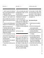
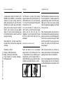
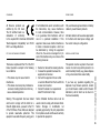
Rx
Owner’s Handbook
contents
pg
introduction
the gemini range
introduction
2
safety notes
3
Thank you for choosing the Bowens Gemini
Rx range of monolights.
The Gemini monolight is a award-winning,
world-class lighting system that has been
designed to the highest possible standards.
using a gemini
3
gemini rx overview
4
2 - Gemini Rx | Introduction and Safety Notes
triggering a gemini rx
5
modelling control and ready indications 6
flash tube, lamp and fuse replacement
6-7
warning and error conditions
7
flash power control
7
flash power dump
8
photocell
8
mounting unit
8
compliance statements
9
trouble shooting
10
specifications
11
In order to obtain the full benefit of this
product, please take a few moments to
familiarise yourself with this user guide.
Whether you are a studio or location based
photographer, the Gemini offers the perfect
lighting solution.
Bowens International Ltd.
Compatible with Bowens award-winning
Travelpak battery, the Gemini offers
photographers the freedom and flexibility of
being able to take your lights anywhere, at
anytime.
Like all Bowens products, the Gemini flash
system has been designed to withstand the
rigors of todays hard working studios and
location shoots.
- do
1.) Switch the power off and disconnect
from the power supply before changing the
modelling lamps or flash tube.
2.) Disconnect the power supply before
changing a fuse. Never replace the fuse
with one of a different rating. A spare fuse is
located in the fuse holder at the rear of the
unit.
3.) Exercise care when handling equipment
that has been in use. The reflector and front
end of the unit can become very hot.
4.) Avoid placing cables where they can be
tripped over. Protect from heavy, sharp or hot
objects that may cause damage and replace
damaged cables immediately.
5.) Due to the high-voltage / high energy
used in the Gemini units, all servicing must
be carried out by a Bowens authorised
service and repair centre.
6.) Remove the power cord by gripping the
plug. Never pull the cord.
7.) Always remove the flash head covers
before using.
safety notes
- do not
1.) Use in an environment where moisture
of flammable liquid is likely to come into
contact with this product.
2.) Plug the Gemini into a mains supply and
a Travelpak battery at the same time.
3.) Restrict air vents while in use.
3.) Use a unit with damaged housing,
mouldings, flash tube or modelling lamp. If
the unit is dropped or damaged in anyway,
always have it checked before using.
5.) Operate the unit without a safe grounded
(earthed) supply.
connecting and using a gemini
Warning high voltage: never connect the
Gemini to both a mains supply and a
Travelpak battery at the same time. This
appliance must be earthed when used with
a mains supply. Disconnect the mains lead
when changing the modelling lamps and
flash tubes. The Gemini may be operated
on either a mains supply or with a Bowens
battery source, such as the Travelpak.
connecting and using a gemini
For mains operation, the ‘Mains / Battery’
power switch (see page 4) should be in the
upper position. For battery operation the
switch should be in the lower position. The
centre position is ‘off’.
power connecting instructions:
1.)Ensure the power source is switched
‘off’.
2.)Connect the unit to the power source
using the appropriate cabling.
3.)If using a battery, ensure the power lead
connectors are fully tightened.
4.)Switch the power source ‘on’, then turn
‘on’ the Gemini.
5.)The unit will charge and indicate it is
ready by illuminating the green LED
on the side of the unit (‘beep’ and ‘lamp’
ready functions are also available to
indicate when unit is 100% charged).
6.)Press the ‘Flash Test’ button on the side
of the unit to check unit fires.
3 - Gemini Rx | Connecting and Using a Gemini
safety notes
gemini rx overview
G
I
H
F
B
A
C
S
D
J
4 - Gemini Rx | Gemini Rx Overview
E
A.)Modelling Lamp
B.)Flashtube
C.)Accessory Release
D.)Power Adjust Dial
E.)Test Flash & Ready Indicator
F.)Carry Handle
G.)Trigger Mode Button
H.)Photo Slave Cell
I.)Pulsar Radio Receiver Antenna
K
M
J.)Lamp Mode
K.)Lamp Level
L.)Ready Beep
M.)1/4” Sync Socket
N.)AC/DC Power Switch
L
N
O
Q
P
R
O.)DC Power Input
P.)AC Power Input
Q.)Fuse Holder
R.)L Bracket
S.)Position Adjustment
Grip
using the built-in pulsar
changing the pulsar studio/channel setting
There are a number of ways to trigger the
Gemini Rx monolight. OPEN FLASH (Fig1.)For testing or multiple flash applications
the ‘Test Flash’ button can be used. SYNC
SOCKET (Fig 2.)- The standard 1⁄4” jack
socket on the rear panel of the unit may be
used for direct connection to a camera or
trigger system. PHOTOCELL (Fig 3.) - The
Gemini has a built-in switchable (on/off)
photocell enabling the unit to be triggered
by an external flash source. PULSAR RADIO
TRIGGER (Fig 4.) - The Gemini Rx features
a built-in Pulsar radio trigger receiver so can
be fired by a Pulsar or Pulsar Tx transmitter.
To fire the Gemini Rx using a Pulsar radio
trigger system, first ensure the unit is
switched ‘on’. In order for the built-in Pulsar
radio receiver to fire the Gemini Rx unit it
must first be synchronised with the users
chosen Pulsar transmitter.
To sync the built-in receiver with a Pulsar
transmitter firstly press the ‘sync’ button (Fig
5.) until the ‘Cell’ icon (Fig 3.) is illuminated.
Once the ‘Cell’ icon is illuminated press and
hold the ‘Sync’ button, the ‘Cell’ icon will go
out and the ‘Radio’ icon (Fig 4.) will turn on
and then start flashing.
When the ‘Radio’ icon starts flashing release
the ‘Sync’ button and then press the test/
open flash button on the Pulsar transmitter
several times until the ‘Radio’ icon stops
flashing, the Gemini Rx unit will flash to
confirm the built-in Pulsar receiver has been
set in occordance to the signal received from
the Pulsar transmitter and that the unit is
ready.
If the Gemini Rx radio receiver is set to a
specific studio/channel and the user needs
to change the setting, simply scroll through
the trigger options using the ‘sync’ button
(Fig 5.) until the ‘Cell’ icon is highlighted.
When the ‘Cell’ icon is highlighted set your
Pulsar transmitter to the new studio/channel
setting required.
Once you have set up the new studio/
channel setting on your Pulsar transmitter,
press and hold the ‘Sync’ button until the
‘Cell’ icon goes out and the ‘Radio’ icon (Fig
4.) starts flashing.
Once the ‘Radio’ icon starts to flash, release
the ‘Sync’ button and press the test/open
flash button on your Pulsar transmitter
several times until the ‘Radio’ icon stops
flashing, when the Pulsar receiver is again
set to the desired studio/channel setting the
Gemini Rx will flash to confirm the change
and that the unit is ready to start shooting.
Two units may be connected together using
a ‘Y’ connector. The sync connection on the
Gemini Rx operates at +5V and is safe to use
with digital cameras.
Fig 1.
Fig 2.
Fig 3.
Fig 4.
Fig 5. Sync Button
5 - Gemini Rx | Triggering the Gemini Rx
triggering the unit
modelling lamp control
unit ready indications
flash tube replacement
The modelling lamp on the GM200Rx and
the GM400Rx uses a phase control system
with a soft ‘on’ and ‘off’ to prolong the life
of the bulb. A ‘lamp saver’ function has
also been incorporated into both units that
will automatically turn on if no adjustments
are made or flashes fired within 30 minutes.
When the ‘lamp saver’ mode turns on the
modelling lamp will ‘dim’ to min power.
The modelling lamp can be used as an
indicator of when the unit is 100% charged
and ready to fire.
The ‘LAMP:MODE’ switch on the rear of
the unit (see page 4) controls the modelling
ready indicator function. When the switch is
set in the ‘lower’ position the modelling lamp
ready indicator will be turned ‘on’, and will
extinguish the lamp when the unit is fired and
will relight once the unit has fully recharged.
If the ‘LAMP:MODE’ switch is set to the
‘centre’ position the modelling ready function
will be turned ‘off’ and the modelling lamp
will remain ‘on’ continuously.
Ensure the unit is switched off and
disconnected from the power supply before
changing the flash tube. Wait for a sufficient
time until the flashtube has cooled down.
Once cooled, unwind the twisted trigger
wire from the flash tube support and gently
pull the flash tube out of the unit. To replace
the flash tube, hold as shown (Fig 6.) while
making sure to support both legs of the flash
tube, and gently push the flash tube into
position. Finally, wind the trigger wire around
the flash tube support. Always replace with
the correct flash tube assembly.
6 - Gemini Rx | Functions Overview
The modelling lamp output is set using the
switches on the rear of the unit (see page 4).
The modelling output can be set to either
‘OFF’ (by setting the LAMP:MODE switch
set to upper position), ‘PROPORTIONAL’ to
the flash output (by setting the LAMP:LEVEL
switch set to lower position) or ‘FULL’ (by
setting the LAMP:LEVEL switch set to upper
position).
Note: When operating the Gemini from a
battery the modelling function is disabled to
preserve the power in the battery.
Both units also have a built-in audible ready
‘beep’ indication where the unit will emit a
short beep to confirm that the unit has 100%
charged and is ready to fire. If the ‘BEEP’
switch on the rear panel of the unit (see page
4) is set in the ‘upper’ position the beep
indication will be turned ‘off’. If the ‘BEEP’
switch is set to the ‘lower’ position the ready
beep will be turned ‘on’.
Fig 6.
warning
Switch off and disconnect the unit from
power supply. If the unit has been in use,
allow a sufficient amount of time to cool
down before touching. Unscrew modelling
lamp from housing and replace with the
correct lamp type (see Fig 7.).
There are four alarms / warnings on the
Gemini Rx to indicate possible function
issues. The alarms / warnings are shown via
the green ready LED; alarms / warnings may
also be accompanied by a beep (if switched
on).
fuse replacement
1.)Charge Fail - Green ready LED will continuously emit a brief flash and
intermittent beep.
The modelling and flash circuitry are
protected by a single 20mm fuse mounted
in the rear panel of the unit. A fuse may blow
when the modelling lamp fails; always check
the fuse when replacing a bulb. A spare fuse
is located in the draw underneath the mains
connection (see Fig 8.) at the rear of the
unit. The fuse draw contains two fuses, the
furthest fuse inside the draw is the live fuse
and the nearest one is a spare. Never replace
the fuse with one of a different rating. Always
switch off the unit and disconnect the power
supply before changing a fuse.
Fig 7.
Fig 8.
2.)Overheat - Green ready LED will flash
once every 2.5 seconds.
3.)Misfire - Green ready LED will flash
twice every 2.5 seconds along with a
beep.
4.)Glow On - GREEN ready LED flashes 3
times every 2.5 seconds accompanied
by a beep.
flash power control
The flash power is set using the single rotary
dial on the side of the unit. The flash power
output is variable over 5 stops, from full to
1⁄32. The max power output is dependant
upon the model (see specifications) and
is denoted by the number 6 on the control
panel. The numeric divisions indicate one
full stop of flash power. Once the unit has
changed to the desired setting, the green
LED will illuminate indicating that the unit is
ready to fire (may also be accompanied by a
beep if switched on).
NB. If the unit is subject to rapid operation
over extended periods, the unit may
automatically go into ‘overheat’. In this
condition, the ready LED will flash every 2.5
seconds while the charging and modelling
functions will be disabled to enable the unit
to cool. The unit will automatically resume
operation once cooled sufficiently.
7 - Gemini Rx | Functions Overview
/ error conditions
modelling lamp replacement
auto flash power dump
photocell
transporting units
A resistive dump facility is included on the
GM200Rx and GM400Rx, to automatically
decrease the power charge should the
setting be reduced by the user. This will be
indicated by the green ready LED flashing
slowly until the power has been ‘dumped’
and the unit is ready at the new desired
setting. The unit can also be flashed using
the ‘Test Flash’ button to reset the unit to the
lower power setting.
The Photocell is a built-in light sensitive
trigger that allows the unit to be fired from an
external flash source. The ‘Sync’ button (Fig
5.) on top of the unit allows the Photocell to
be switched on or off.
To turn the photocell ‘on’ simply use the
‘Sync’ button to scroll through the trigger
options until the ‘Cell’ icon (Fig 3.) is
highlighted. To turn the photocell ‘off’ press
the ‘Sync’ button until the ‘Cell’ icon is not
illuminated.
When transporting any Bowens units, ensure
that all equipment is carefully packed into
appropriate bags and/or hard shell cases.
Make sure all items are securely placed
inside the appropriate baggage to protected
from any knocks.
8 - Gemini Rx | Functions Overview
Green Ready LED - The green ready LED on
the side of the unit shows the charge state
as follows:
Powerdown - LED off.
Charging - LED flashes quickly.
Ready - LED stays lit continuously.
Power Dumping (or requires dumping) LED flashes slowly.
mounting unit to support stand
Mount the Gemini unit on the selected
support system. The mounting bush on the
‘L’ bracket allows for two possible ways of
mounting the unit to the support stand - A
and B. Method B may be used if the light is
required to point either directly up or down.
A.
B.
When transporting flash units make sure to
fully discharge flash power before packing. A
quick way to ensure a unit is discharged is to
turn the unit on, wait for it to charge to 100%
and then open flash the unit using the ‘test’
button, then quickly turn off before the unit
has recharged.
Flash units can become very hot after use.
Always wait a minimum of 30 minutes before
packing to allow units to cool sufficiently.
If any unit is dropped and/or knocked during
transport, always have the unit checked by
an authorised Bowens service/repair centre
before using.
All Bowens products are
certified by the CE mark.
The CE certified mark is a
declaration of conformity
to the required EEC directives 89/336/EEC
‘Electromagnetic Compatibility’ and 73/23/
EEC ‘Low Voltage Directive’.
fcc class b compliance statement
This device complies with Part 15 of the FCC
Rules. Operation is subject to the following
two conditions:
power cables
if not installed and used in accordance with
the instructions, may cause interference
to radio communications. However, there
is no guarantee that interference will not
occur in a particular installation. If this
equipment does cause harmful interference
to radio or television reception, which can
be determined by turning the equipment
off and on, the user is encouraged to try to
correct the interference by one or more of the
following measures:
•This device may not cause harmful interference.
•This device must accept any interference received, including interference that may cause undesired operation.
• Reorient or relocate the receiving antenna.
• Increase the separation between the
equipment and receiver.
• Connect the equipment into an outlet
on a circuit different from that to which the
receiver is connected.
• Consult the dealer or an experienced
radio/TV technician for help.
Warning: This equipment has been tested
and found to comply with the limits for a
Class B digital device, pursuant to Part 15
of the FCC Rules. These limits are designed
to provide reasonable protection. This
equipment uses radio frequency energy and,
Notice: Shielded interface cable must be
used in order to comply with emission limits.
Notice: Changes or modification not
expressly approved by the party responsible
for compliance could void the user’s authority
to operate the equipment.
Only use Bowens approved mains or battery
cables to power Bowens products.
All mains cables must be used as appropriate
to the flash units rated power voltage, and
the correct mains pin-configuration.
disposal and recycling
This product must be recycled in the correct
manner. In order to recycle this product in an
environmentally friendly way, please dispose
of at your local electronic waste facility.
If you have any questions regarding the
disposal of any Bowens products, contact
your local Bowens retailer and/or Bowens
distributor (a list of which can be found on
the bowens website).
9 - Gemini Rx | Compliance Statements
ce marking
10 - Gemini Rx | Trouble Shooting
trouble shooting
Problem?
Check.
Problem?
Check.
Problem?
Check.
No Power
• Check the unit is switched ‘on’.
• Check the power cable is inserted
correctly.
• If using a mains cable, check the
fuse on the plug.
Unit will not
recharge
Unit appears
ready but won’t
fire
No Flash
• Check flash tube is inserted into the
flash head correctly.
• Check the trigger wire is in contact
with the flash tube support.
• Change the flash tube. If changing
the flash tube does not correct the
fault, the unit may have a
component failure. If problem
persists, return the unit to your local
Bowens service / repair centre.
• Check power cable is inserted
correctly.
• If using a battery, check battery has
sufficient charge remaining to
power the unit.
• Change the fuse at the rear of the
unit.
• Check the units voltage supply is
correct. If problem continues,
return the unit to an authorised
Bowens service / repair centre.
• If the unit appears ready but will
not fire i.e. power is on and green
ready LED displayed but unit will
not fire; the unit may be in
‘overheat’ mode.
• The units ‘trigger mode’ may be set
incorrectly i.e. the user may be
trying to trigger the unit from a
Pulsar trigger system with the unit
set to ‘Cell’ or ‘off’.
Ready ‘beep’
not working
• Check the BEEP switch at the rear
of the unit is turned ‘on’.
• Make sure unit is reaching full
recharge. If unit continues with
problem return to an authorised
Bowens service / repair centre.
Flash tube only
emits a faint
glow and will
not fire
• Check flash tube is inserted into the
unit correctly and all connections
are made.
• Change flash tube. If unit continues
with problem return to an
authorised Bowens service / repair
centre.
Unit won’t
fire from ‘sync’
connection
• Check the sync cord / trigger
system is inserted into the
trigger system correctly. Check the
connections at both ends of the
cord are okay.
• Try another sync cord.
Modelling Lamp • Change the modelling lamp.
not working
• Change fuse at rear of unit. If
problem continues, return the unit
to your nearest Bowens service /
repair centre.
Unit will
not flash from
Photocell
• Check the Photocell is switched
‘on’.
• Check Photocell is not covered
and can ‘see’ the trigger flash. If
problem continues, return the unit
to an authorised Bowens service /
repair centre.
Legal Notice.
Bowens® and ‘the power behind the picture’® are
registered trademarks of Bowens International Ltd.
Due to out policy continual product imp[rovement,
Bowens INternational Ltd reserves the right to
change equipment specifications at any time and
without notice. The information contained in this
user guide should not be relied on solely before
making a purchase, seek further information
from your photographic retailer. © 2010 Bowens
International Ltd.
Gemini 200Rx (117V)
Gemini 400Rx (117V)
Gemini 200Rx (230V)
Gemini 400Rx (230V)
Sync Voltage
5V
5V
5V
5V
Colour Temperature
5600K (±300K)
5600K (±300K)
5600K (±300K)
5600K (±300K)
Fuse Rating
10A F
10A F
5A F
5A F
Supply Voltage AC
95-130VAC 50/60Hz
95-130VAC 50/60Hz
190-250VAC 50/60Hz
190-250VAC 50/60Hz
Flash Power Stability
±1%
±1%
±1%
±1%
Guide No @ 3m with 50º Keylite
60
80
60
80
Recycle Time (to full)
1.1 seconds
1.65 seconds
0.7 seconds
1.2 seconds
Modelling Control
Mode (Off/Cont/Int)
Level (Full/Prop)
Mode (Off/Cont/Int)
Level (Full/Prop)
Mode (Off/Cont/Int)
Level (Full/Prop)
Mode (Off/Cont/Int)
Level (Full/Prop)
Modelling Level Control
Full to 1/32 5 stops
Full to 1/32 5 stops
Full to 1/32 5 stops
Full to 1/32 5 stops
Flash Duration t=0.5
1/1450
1/1000
1/1450
1/1000
Flash Power Control
Full to 1/32 5 stops
Full to 1/32 5 stops
Full to 1/32 5 stops
Full to 1/32 5 stops
Modelling Lamp
Max 275W
Max 275W
Max 275W
Max 275W
Ready Indication
100%
100%
100%
100%
Flash Tube
UV=BW2032
Clear=BW2030
UV=BW2032
Clear=BW2030
UV=BW2032
Clear=BW2030
UV=BW2032
Clear=BW2030
Photocell
On/Off
On/Off
On/Off
On/Off
Radio
On/Off/Channel Select
On/Off/Channel Select
On/Off/Channel Select
On/Off/Channel Select
Sounder
On/Off
On/Off
On/Off
On/Off
Modelling Lamp
250W 117V - BW1024B
250W 117V - BW1024B
250W 230V - BW1024A
250W 230V - BW1024A
Weight
2.6Kg
2.8Kg
2.5Kg
2.7Kg
Dimensions (LxWxH) - mm
320 x 150 x 150mm
320 x 150 x 150mm
320 x 150 x 150mm
320 x 150 x 150mm
Dimensions (LxWxH) - inches
12.5” x 6” x 6”
12.5” x 6” x 6”
12.5” x 6” x 6”
12.5” x 6” x 6”
11 - Gemini Rx | Specifications
Specifications
Rx
BWL-0620 | Gemini Rx - 200 and 400
www.bowens.co.uk
04/2012