1
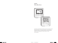
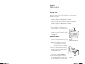
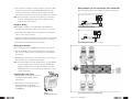
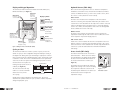
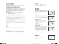
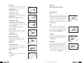
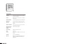
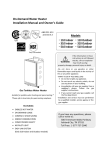
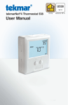
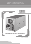
RADIANT HEATING SYSTEMS
SETPOINT 501 AND 501 S
CONTROLLERS
SetPt501_501s_InstOperManual_3_07, Copyright © 2007 Uponor, Printed in the United States
INSTALLATION AND
OPERATION MANUAL
Uponor, Inc.
5925 148th Street West
Apple Valley, MN 55124
Tel: (800) 321-4739
Fax: (952) 891-1409
Web: www.uponor-usa.com
E-mail: [email protected]
Uponor Ltd.
655 Park Street
Regina, SK S4N 5N1
Tel: (888) 994-7726
Fax: (800) 638-9517
Web: www.uponor.ca
E-mail: [email protected]
SetPoint 501 and 501s Controllers
Installation and Operation Manual
Table of Contents
Section 1 — Introduction . . . . . . . . . . . . . . . . . . . . . . . . . . . . . . 1
Section 2 — Installation
Getting Ready . . . . . . . . . . . . . . . . . . . . . . . . . . . . . . . . . . . . . . . . . . . . 3
Removing the Front Cover . . . . . . . . . . . . . . . . . . . . . . . . . . . . . . . . . . . 3
Mounting the Base . . . . . . . . . . . . . . . . . . . . . . . . . . . . . . . . . . . . . . . . 3
Rough-in Wiring . . . . . . . . . . . . . . . . . . . . . . . . . . . . . . . . . . . . . . . . . . 4
Wiring the Controller . . . . . . . . . . . . . . . . . . . . . . . . . . . . . . . . . . . . . . . 4
Installing the Front Cover . . . . . . . . . . . . . . . . . . . . . . . . . . . . . . . . . . . 4
Wiring Examples . . . . . . . . . . . . . . . . . . . . . . . . . . . . . . . . . . . . . . . . . . 5
Display and Keypad Operation . . . . . . . . . . . . . . . . . . . . . . . . . . . . . . . 6
Cycles per Hour . . . . . . . . . . . . . . . . . . . . . . . . . . . . . . . . . . . . . . . . . . . 6
Optional Sensors . . . . . . . . . . . . . . . . . . . . . . . . . . . . . . . . . . . . . . . . . . 7
Access Levels . . . . . . . . . . . . . . . . . . . . . . . . . . . . . . . . . . . . . . . . . . . . . 7
Sequence of Operation . . . . . . . . . . . . . . . . . . . . . . . . . . . . . . . . . . . . . 8
Mode . . . . . . . . . . . . . . . . . . . . . . . . . . . . . . . . . . . . . . . . . . . . . . . . . . . 8
Section 3 — Navigating the Menus
View Menu . . . . . . . . . . . . . . . . . . . . . . . . . . . . . . . . . . . . . . . . . . . . . . 9
Adjust Menu . . . . . . . . . . . . . . . . . . . . . . . . . . . . . . . . . . . . . . . . . . . . . 9
Section 4 — Troubleshooting
Error Messages . . . . . . . . . . . . . . . . . . . . . . . . . . . . . . . . . . . . . . . . . . 11
Section 5 — Technical Data
SetPoint 501 . . . . . . . . . . . . . . . . . . . . . . . . . . . . . . . . . . . . . . . . . . . . 13
SetPoint 501s . . . . . . . . . . . . . . . . . . . . . . . . . . . . . . . . . . . . . . . . . . . 14
SetPoint 501 and 501s Controllers Installation and Operation Manual
Published by Uponor, Inc.
5925 148th Street West
Apple Valley, MN 55124
(800) 321-4739
www.uponor-usa.com
© 2007 Uponor, Inc.
All rights reserved
Third Edition, March 2007
First Printing, November 2002
Printed in the United States of America
SetPoint 501 and 501s Controllers Manual
i
Section 1
Introduction
SetPoint 501
SetPoint 501s
The SetPoint 501 and 501s Controllers are microprocessor-based controls
that are designed to sense the air temperature in a specific area and
increase the comfort level of that area as well as increase the energy
efficiency of the heating system. The 501s will also monitor
slab temperature.
ii
Section 1 — Introduction
1
Section 2
Installation
Getting Ready
Check the contents of this package. If any contents listed below are
missing or damaged, please contact your Uponor sales representative or
distributor for assistance.
• SetPoint 501 (part number A3040501) includes one controller, an
Installation and Operation Manual and a User Manual.
• SetPoint 501s (part number A3041501) includes one programmable
Setpoint Controller, one Floor Sensor (part number A3040079), an
Installation and Operation Manual and a User Manual.
Removing the Front Cover
1. Place a screwdriver or similar object into the
small slot located in the top of the controller.
.
.
2. Push the screwdriver against the plastic tab
and pull the top of the front cover so that it
pivots around the bottom edge of the base.
(See Figure 1.)
Mounting the Base
1. Install the controller on an interior wall of
the desired zone approximately 5 feet (1.5m)
above the floor.
Figure 1:
Removing the Front Cover
Note: Do not mount the controller in a
location that may be affected by
localized heat sources or cold drafts.
2. If necessary, install a draft barrier behind
the controller to prevent air from blowing
through the wiring hole and affecting the
controller’s built-in sensor.
3. Mount the base directly to the wall using
two #6 1-inch screws. (See Figure 2.)
4. Insert the screws through the mounting
holes, and fasten the base securely to the
wall. If possible, at least one of the screws
should enter a wall stud or similar surface.
2
Section 2 — Installation
#6 1" screws
Figure 2:
Mounting the Base
3
5. If the controller is mounted to a 2x4 electrical box, order a Cover Plate
for the 500 Series Controllers (part number A3040007). This plate
mounts to the electrical box and the controller mounts to the plate.
Ensure that the electrical box does not provide cold air to the controller.
Wiring Examples for the SetPoint 501 and SetPoint 501s
Refer to the figures below to wire 24VAC power and the optional sensor.
Note: If the SetPoint 501s is used for remote sensing (i.e., the built-in
air sensor is disabled and an indoor sensor is used), mount the
controller in the desired location.
Rough-in Wiring
Note: 18 AWG or similar wire is recommended for all 24VAC wiring.
Figure 4: Wiring the SetPoint 501
1. Strip all wires to ⁄4" (6mm) to ensure proper connection to the control.
1
2. Run wires from the 24VAC power to the controller. Use a clean power
source to ensure proper operation.
Com S1
C
R
Heat
Class II
Transformer 24VAC
3. If using an optional sensor, install the sensor according to the appropriate
instruction sheet and run two wires from the sensor to the controller.
4. Run wires from the heating device to the controller.
Figure 5: Wiring the SetPoint 501s
Wiring the Controller
Refer to the wiring examples on page 5 to properly wire the controller.
1. Connect the 24VAC power to the R and C terminals on the controller.
This connection provides power to the microprocessor and display of
the controller.
2. When wiring an optional sensor to the SetPoint 501s, connect the two
wires from the sensor to the Com and S1 terminals.
Note: The Heat terminals are isolated outputs. There is no power available
on these terminals from the controller. Use these terminals as a
switch for a 24VAC circuit. This circuit can operate a low-current,
24VAC device directly or an external relay to enable a line-voltage
or high-current device.
Installing the Front Cover
1. Align the hinges on the bottom of the front
cover with the bottom of the controller
mounting base.
2. Pivot the front cover around the bottom
hinges and push the top against the
mounting base until it snaps firmly in place.
(See Figure 3.)
Figure 3:
Installing the Front Cover
4
Figure 6: Wiring the Zone Control Module (ZCM)
Section 2 — Installation
5
Display and Keypad Operation
Optional Sensors (501s Only)
The SetPoint 501 and 501s Controllers feature four fields: Menu, Item,
Number and Status. (See Figure 7.)
Each controller has a single built-in sensor to measure air temperature.
In addition to this built-in sensor, the SetPoint 501s features terminals to
connect one additional sensor (i.e., indoor sensor, outdoor sensor, slab or
floor sensor or sensor placed in a remote location).
Item Field
Displays the
current menu
Display Symbols
Warning
Displays when
an error exists
Access Level
(501s Only)
Displays when
in the User
Access Level
Status Field
Displays the current
status of the
thermostat’s inputs,
outputs and operation
Heat 1
Displays when
the Heat 1
contact is on
Number Field
Buttons
Selects menus, items
and adjusts settings
Displays the
current value of
the selected item
Figure 7: Wiring the Zone Control Module (ZCM)
Cycles per Hour
The SetPoint 501 and 501s controllers operate on cycles per hour. The
number of cycles per hour is adjustable through the Heat Cycle setting in
the Adjust menu. During each cycle that heating is required, the controller
turns on the Heat relay for a calculated amount of time. This amount of time
is called the on time. The on time is calculated based on the requirements
of the zone. If the zone requires more heating, the appropriate on time is
increased. If the zone requires less
Cycles Per Hour
heating, the appropriate on time is
reduced. (See Figure 8.)
on
on
on
off
off
off
The controller ensures the relay
remains on or off for a minimum
amount of time to prevent
short cycling.
Time
Figure 8: Cycles per Hour
Indoor Sensor
An indoor sensor measures the air temperature in the zone that the
SetPoint is controlling. The temperature measured by the outdoor sensor
is used in the on-time calculations for the relay in the controller. Select this
setting on the Adjust menu. If the built-in sensor is on and the auxiliary
sensor is set to Indoor, the temperatures of the sensors are averaged and
used to calculate the on time of the relay.
Outdoor Sensor
An outdoor sensor measures the temperature of the air outside. The
temperature measured by the outdoor sensor does not affect the on time
of the relay and is only used for display purposes.
Slab or Floor Sensor
A slab or floor sensor measures the slab or floor temperature in the zone
that the controller is controlling. The temperature the slab or floor sensor
reads is used in the on-time calculations for the Heat relay and allows the
controller to operate the slab between the minimum and maximum
slab settings.
Access Levels (501s Only)
The SetPoint 501s features two access levels —
User and Installer — which restrict the number
of items available in the display menus. Change
the access level via the DIP switch located on
the circuit board inside the controller. (See
Figure 9.)
The Installer access level allows the installer to
adjust all the settings in the controller including
those required to match the controller to the
mechanical system and devices. The User access
level allows the end user to adjust the
temperature settings.
501s
Displays an
abbreviated
name of the
selected item
Menu Field
Figure 9:
DIP Switch Location
An Auto Cycle setting is available for the heating cycle. This setting
determines the optimum number of cycles per hour to balance temperature
swings and equipment cycles.
6
Section 2 — Installation
7
Sequence of Operation
Section 3
Air Sensor Only Operation
When operating with only an air sensor, the on time for the Heat relay is
calculated to satisfy the requirements of the air sensor.
Navigating the Menus
Slab or Floor Sensor Only Operation (501s Only)
When operating with only a slab or floor sensor, the on time for the Heat
relay is calculated to satisfy the requirements of the slab or floor sensor.
The controller operates to maintain the slab at the minimum slab
temperature setting.
Note: Using only a slab or floor sensor may cause overheating or
underheating of the space.
View Menu
ROOM TARGET
This displays the current desired air temperature
for the space (one active air sensor required). This
is only available when in the Installer access level.
(See Figure 10.)
Air and Slab or Floor Sensor Operation (501s Only)
When operating with both air and slab or floor sensors, the controller
calculates an on time for the Heat relay to satisfy the slab or floor sensor’s
requirements and an on time to satisfy the air sensor’s requirements. The
Heat relay operates for the longer of these two on times.
ROOM
This displays the current air temperature for the
space that is the average of all active air sensors
(one active air sensor required). (See Figure 11.)
During light heating loads, overheating can occur due to the minimum slab
or floor temperature requirements.
OUTDOOR (501s Only)
This displays the current temperature at the
outdoor sensor. An outdoor sensor must be
installed for this menu to function.
(See Figure 12.)
During heavy heating loads, the maximum slab or floor temperature
setting limits the on time of the Heat relay. In this situation, underheating
can occur.
Off
The Heat relay does not operate in the Off mode.
Note: If an air, slab or floor sensor is active in the Off mode, a freezeprotection function enables, allowing the Heat relay to operate
and keep the zone above 35°F (2°C).
Figure 11
Note: SENS must be set to OUT.
Mode
Heat
In the heat mode, the Heat relay satisfies the temperature requirement of
the zone.
Figure 10
SLAB (501s Only)
This displays the current slab or floor temperature
(one active air sensor required). If two slab or
floor sensors are present, this is the average
temperature. MIN is displayed when the slab or
floor minimum temperature is calling for heat.
The slab or floor sensor may call for heat even
though the room setpoint temperature is satisfied.
(See Figure 13.)
Figure 12
Figure 13
Adjust Menu
MODE
This displays the current mode of operation of
the thermostat. (See Figure 14.)
OFF, HEAT
Figure 14
8
Section 3 — Navigating the Menus
9
Section 4
ROOM HEAT
This displays the desired temperature for heating
(must set active air sensor to Heat or Auto).
(See Figure 15.)
35 to 100°F (2 to 38°C)
Troubleshooting
SLAB MIN (501s Only)
This displays the minimum slab or floor
temperature (one active slab sensor required).
(See Figure 16.)
OFF, 34 to 122°F (OFF, 1 to 50°C)
Figure 15
SLAB MAX (501s Only)
This displays the maximum slab or floor
temperature (one active air sensor required).
This is only available when in the Installer access
level. (See Figure 17.)
34 to 122°F, OFF (1 to 50°C, OFF)
Figure 16
Figure 17
SENS (501s Only)
This selects the type of optional sensor present
(only available in the Installer access level).
(See Figure 18.)
OFF, Indr, SLAB, OUT
Error Messages
E01
The controller was unable to read a piece of
information stored in its memory and was required
to load the factory settings. The controller will
stop operation until all settings are checked. To
clear this error, select the Installer access level
and check all of the settings in the Adjust menu.
(See Figure 22.)
Figure 22
E02
There are no active sensors selected on the
controller. Either turn on the internal sensor or
set the auxiliary sensor to INDR or SLAB. After
correcting the fault, press any button to clear
the error message. (See Figure 23.)
Figure 23
Figure 18
ROOM SENS (501s Only)
This enables or disables the built-in sensor
(only available in the Installer access level).
(See Figure 19.)
OFF, ON
Figure 19
CYC HEAT (501s Only)
This displays the number of cycles per hour
for heating (only available in the Installer access
level). (See Figure 20.)
AUTO, 2 to 12
Figure 20
ROOM Shr
The controller’s internal air sensor has a short
circuit. This error cannot be repaired in the field.
Replace or return the controller for repair.
(See Figure 24.)
ROOM OPN
The controller’s internal air sensor has an open
circuit. This cannot be repaired in the field.
Either turn off the internal sensor and set an
auxiliary sensor to INDR, or replace the controller
and return the faulty controller for repair. After
correcting the fault, press any button to clear
the error message. (See Figure 25.)
Figure 24
Figure 25
UNITS
This displays the units of temperature used.
(See Figure 21.)
°F, °C
Figure 21
10
Section 4 — Troubleshooting
11
Section 5
SENS Shr
The optional sensor has a short circuit. Locate
and repair the problem as described in the
appropriate sensor instruction sheet. After
correcting the fault, press any button to clear
the error message. (See Figure 26.)
Technical Data
Figure 26
SENS OPN
The optional sensor has an open circuit. Locate
and repair the problem as described in the
appropriate sensor instruction sheet. After
correcting the fault, press any button to clear
the error message. (See Figure 27.)
Figure 27
Figure 28: SetPoint 501
SetPoint 501
12
Literature
SetPoint 501 and 501s Controllers Installation
and Operation Manual
Control
Microprocessor PI control; This is not a safety
(limit) control.
Packaged Weight
0.46 lb. (210 g), Enclosure J, white PVC plastic
Dimensions
2 7⁄8" H x 2 7⁄8" W x 13⁄16" D (73 x 73 x 21mm)
Approvals
CSA C US, meets ICES and FCC regulations for
EMI/RFI
Ambient Conditions
Indoor use only, -22 to 131°F (-30 to 55°C),
<90% RH non-condensing
Power Supply
24VAC ±10% 50/60 Hz 1 VA
Relay
24VAC, 2 A
Section 5 — Technical Data
13
Figure 29: SetPoint 501s
SetPoint 501s
14
Literature
SetPoint 501 and 501s Controllers Installation
and Operation Manual
Control
Microprocessor PI control; This is not a safety
(limit) control.
Packaged Weight
0.54 lb. (245 g), Enclosure J, white PVC plastic
Dimensions
2 7⁄8" H x 2 7⁄8" W x 13⁄16" D (73 x 73 x 21mm)
Approvals
CSA C US, meets ICES and FCC regulations for
EMI/RFI
Ambient Conditions
Indoor use only, -22 to 131°F (-30 to 55°C),
< 90% RH non-condensing
Adjustment Range
for Slab or Floor
Setting
34 to 122°F (1 to 50°C)
Power Supply
24VAC ±10% 50/60 Hz 1.5 VA
Relay
24VAC, 2 A
Sensors
NTC thermistor, 10 kΩ @ 77°F (25°C ±0.2°C)
ß=3892
Included
Floor Sensor (A3040079)
Optional
Outdoor Sensor (A3060070), Universal Sensor
(A3060071) and Epoxy-coated Slab Sensor
(A3060072)