1
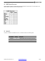
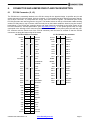
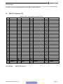
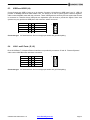
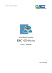
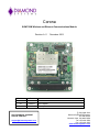
Corona
SUMIT-ISM Wireless and Ethernet Communications Module
Revision A.11
Revision
Date
A
12/13/2010
Initial Release
A.1
2/8/2012
Rev B Update
A.11
12/3/2012
Minor updates
FOR TECHNICAL SUPPORT
PLEASE CONTACT:
[email protected]
December 2012
Comment
Copyright 2012
Diamond Systems Corporation
555 Ellis Street
Mountain View, CA 94043 USA
Tel 1-650-810-2500
Fax 1-650-810-2525
www.diamondsystems.com
CONTENTS
1.
2.
Important Safe Handling Information .............................................................................................................3
Introduction .......................................................................................................................................................4
2.1 Features .........................................................................................................................................................4
2.2 SUMIT Socket Resources .............................................................................................................................5
2.3 Cable Kit ........................................................................................................................................................5
3. Functional Overview .........................................................................................................................................6
3.1 Functional Block Diagram ..............................................................................................................................6
3.2 WiFi Module ...................................................................................................................................................7
3.3 PLX PEX8112 PCIe to PCI Bridge Chip ........................................................................................................7
3.4 Dual 10/100 USB LAN Controllers ................................................................................................................7
3.5 Chrontel CH7317B SDVO to VGA Controller ................................................................................................7
4. Board Outline and Layout ................................................................................................................................8
4.1 Corona Board Drawing ..................................................................................................................................8
5. Connector AND Jumper List ......................................................................................................................... 10
6. Connector and Jumper Pinout and Pin Description .................................................................................. 11
6.1 PC/104 Connector (J1, J2) ......................................................................................................................... 11
6.2 Mini-PCI Connector (J3) ............................................................................................................................. 12
6.3 USB2 and USB3 (J4) .................................................................................................................................. 13
6.4 LAN 1 and 2 Ports (J5, J6) ......................................................................................................................... 13
6.5 SDVO Video Input (J7) ............................................................................................................................... 14
6.6 VGA Video Output (J8) ............................................................................................................................... 14
6.7 PCIe Routing Jumper (J13) ........................................................................................................................ 15
6.8 SUMIT-A Expansion Bus (J11) ................................................................................................................... 16
7. Installation and configuration ...................................................................................................................... 17
7.1 Attaching Corona to the Aurora SBC ......................................................................................................... 17
7.2 Attaching External Antennas to the WiFi Module ....................................................................................... 17
7.3 Installing WiFi Drivers ................................................................................................................................. 17
8. Specifications................................................................................................................................................. 18
CORONA User Manual Rev A.11
www.diamondsystems.com
Page 2
1.
IMPORTANT SAFE HANDLING INFORMATION
WARNING!
ESD-Sensitive Electronic Equipment
Observe ESD-safe handling procedures when working with this product.
Always use this product in a properly grounded work area and wear appropriate
ESD-preventive clothing and/or accessories.
Always store this product in ESD-protective packaging when not in use.
Safe Handling Precautions
The Corona board contains a high density connector with many connections to sensitive electronic components.
This creates many opportunities for accidental damage during handling, installation and connection to other
equipment. The list here describes common causes of failure found on boards returned to Diamond Systems for
repair. This information is provided as a source of advice to help you prevent damaging your Diamond (or any
vendor’s) embedded computer boards.
ESD damage – This type of damage is usually almost impossible to detect, because there is no visual sign of
failure or damage. The symptom is that the board eventually simply stops working, because some component
becomes defective. Usually the failure can be identified and the chip can be replaced. To prevent ESD damage,
always follow proper ESD-prevention practices when handling computer boards.
Damage during handling or storage – On some boards we have noticed physical damage from mishandling. A
common observation is that a screwdriver slipped while installing the board, causing a gouge in the PCB surface
and cutting signal traces or damaging components.
Another common observation is damaged board corners, indicating the board was dropped. This may or may not
cause damage to the circuitry, depending on what is near the corner. Most of our boards are designed with at
least 25 mils clearance between the board edge and any component pad, and ground / power planes are at least
20 mils from the edge to avoid possible shorting from this type of damage. However these design rules are not
sufficient to prevent damage in all situations.
A third cause of failure is when a metal screwdriver tip slips, or a screw drops onto the board while it is powered
on, causing a short between a power pin and a signal pin on a component. This can cause overvoltage / power
supply problems described below. To avoid this type of failure, only perform assembly operations when the
system is powered off.
Sometimes boards are stored in racks with slots that grip the edge of the board. This is a common practice for
board manufacturers. However our boards are generally very dense, and if the board has components very close
to the board edge, they can be damaged or even knocked off the board when the board tilts back in the rack.
Diamond recommends that all our boards be stored only in individual ESD-safe packaging. If multiple boards are
stored together, they should be contained in bins with dividers between boards. Do not pile boards on top of each
other or cram too many boards into a small location. This can cause damage to connector pins or fragile
components.
Power supply wired backwards – Our power supplies and boards are not designed to withstand a reverse
power supply connection. This will destroy each IC that is connected to the power supply (i.e. almost all ICs). In
this case the board will most likely will be unrepairable and must be replaced. A chip destroyed by reverse power
or by excessive power will often have a visible hole on the top or show some deformation on the top surface due
to vaporization inside the package. Check twice before applying power!
Overvoltage on analog input – If a voltage applied to an analog input exceeds the design specification of the
board, the input multiplexor and/or parts behind it can be damaged. Most of our boards will withstand an
erroneous connection of up to 35V on the analog inputs, even when the board is powered off, but not all boards,
and not in all conditions.
Overvoltage on analog output – If an analog output is accidentally connected to another output signal or a
power supply voltage, the output can be damaged. On most of our boards, a short circuit to ground on an analog
output will not cause trouble.
Overvoltage on digital I/O line – If a digital I/O signal is connected to a voltage above the maximum specified
voltage, the digital circuitry can be damaged. On most of our boards the acceptable range of voltages connected
to digital I/O signals is 0-5V, and they can withstand about 0.5V beyond that (-0.5 to 5.5V) before being damaged.
However logic signals at 12V and even 24V are common, and if one of these is connected to a 5V logic chip, the
chip will be damaged, and the damage could even extend past that chip to others in the circuit.
CORONA User Manual Rev A.11
www.diamondsystems.com
Page 3
2.
INTRODUCTION
Corona is a SUMIT-ISM form factor wireless and Ethernet Communications module with SUMIT-A and PC/104
(ISA) expandability.
High Power Output
Diamond’s Corona SUMIT Communications module offers high powered performance in a compact form factor,
with peak wireless power up to 600mW. The on-module heatsink assures consistent power output.
Designed for Outdoor Applications
Corona was designed with outdoor applications in mind. It is ideal for access point applications or a wide range of
other embedded computing applications.
Rugged and Robust
Extended temperature operation of -40°C to +85°C is tested and guaranteed. The mini-PCI wireless module
mounts securely to the carrier through a standoff and screw.
Expandability
The Corona SUMIT Communications module has both SUMIT-A and PC/104 (ISA) stackthrough expandability.
Therefore it can be used in legacy PC/104 stacks as well as new SUMIT-based architectures.
2.1
Features
WiFi module
802.11a/b/g mini-PCI wireless LAN
Up to 108Mbps transmit & receive rates
Average power up to 23dBm
Peak power up to 28dBm
Reliable high radio power
Module secured to carrier board
I/O
Dual on-board 10/100Base-T Ethernet ports
Dual USB 2.0 Ports
SDVO to VGA Converter
Miscellaneous
SUMIT-A and PC/104 (ISA) stackable expansion
Extremely rugged -40°C to +85°C (-40°F to +185°F) operating temperature
WiFi support for Windows XP and Linux
CORONA User Manual Rev A.11
www.diamondsystems.com
Page 4
2.2
SUMIT Socket Resources
Corona’s SUMIT-A expansion socket uses the resources indicated in the table below. For further details on the
SUMIT expansion standard, visit SFF-SIG.org/sumit.html.
2.3
Cable Kit
A cable kit, C-COR-KIT, is available for Corona. It contains the cables in the following table.
Part Number
Quantity
Description
6981080
2
Ethernet cable, 2mm 2x5 crimp to RJ-45 socket
6981082
1
Dual USB cable, 2mm 2x5 to Dual USB
6981084
1
VGA cable, 2mm 2x5 crimp to DD15F
CORONA User Manual Rev A.11
www.diamondsystems.com
Page 5
3.
FUNCTIONAL OVERVIEW
3.1
Functional Block Diagram
Block Diagram
coax
PCIe x1
PLX
PEX8112
PCI
Wireless
LAN
SUMIT – A +3.3V
Connector
Voltage
Regulator
USB0
USB LAN
Controller
Magnetics
10/100
Ethernet
USB1
USB LAN
Controller
Magnetics
10/100
Ethernet
USB 2, 3
SDVO
Connector
SDVO to
VGA
Analog Level
Shifters
Analog
VGA
The Corona SUMIT Communications module features both wireless and networking connectivity in the SUMITISM Type I form factor. The product contains a WiFi card connected via a mini-PCI socket, two 10/100Base-T
Ethernet ports, two USB 2.0 ports if supported by the host system, an SDVO to VGA converter, and both a
SUMIT-A connector and a PC104 (ISA) connector for expansion.
The wireless WiFi card is a mini-PCI IEEE 802.11 wireless LAN. Its average power is up to 200mW with peak
power up to 600mW.
The on-board dual 10/100Base-T Ethernet ports provide a high speed option for communication with remote
hosts.
The SDVO to VGA converter takes an externally provided SDVO input and converts it to an analog VGA output.
It is designed for use with Diamond’s Aurora single board computer.
CORONA User Manual Rev A.11
www.diamondsystems.com
Page 6
3.2
WiFi Module
The WiFi module is an industrial grade, high power 600mW (28dBm) IEEE802.11a/b/g 108Mbps Wifi mini-PCI
module with two U.FL RF connectors designed specifically for operation in high temperature and high
performance-critical applications.
With industrial grade components and a high power design, the module is ideal for embedding into new or
existing industrial grade systems for rugged outdoor point to point or building to building wireless Access
Point/Bridge connections, and rugged application-specific devices used in many vertical markets.
3.3
PLX PEX8112 PCIe to PCI Bridge Chip
The PEX 8112 supports forward and reverse bridging as defined by the PCI Express-to-PCI/PCI-X Bridge
Specification 1.0. In forward mode, the bridge allows legacy PCI chips and adapters to be used with new PCI
Express processor systems.
PCIE Interface
PCI Express Base 1.0a compliant
X1 Link, dual-simplex, 2.5Gbps per direction
Automatic LVDS polarity reversal
PCI Interface
PCI v.3.0: 32bit, up to 66Mhz
3.3VI/O and 5V tolerant PCI
Provides PCI clock output
3.4
Dual 10/100 USB LAN Controllers
Single Chip Hi-Speed USB 2.0 to 10/100 Ethernet Controller
Integrated 10/100 Ethernet MAC with Full Duplex and HP Auto-MDX support
Integrated USB 2.0 High Speed PHY and Device Controller
+/- 8kV HBM ESD protection (component level)
+/- 8kV contact-discharge, +/-15kV air discharge ESB protection per IEC61000-4-2
3.5
Chrontel CH7317B SDVO to VGA Controller
Supporting analog RGB outputs for a display monitor
Supporting maximum pixel rate of 165MP/s or graphics resolutions up to 1920x1200
High-speed SDVO (1G~2Gbps) AC-coupled serial differential RGB inputs
Supporting monitor connection detection
CORONA User Manual Rev A.11
www.diamondsystems.com
Page 7
4.
BOARD OUTLINE AND LAYOUT
4.1
Corona Board Drawing
The following diagram shows locations for all connectors identified in the next section.
Corona Top
CORONA User Manual Rev A.11
www.diamondsystems.com
Page 8
Corona Bottom
CORONA User Manual Rev A.11
www.diamondsystems.com
Page 9
5.
CONNECTOR AND JUMPER LIST
The following table summarizes the functions of Corona’s interface connectors and jumpers. Please refer to the
drawings in Section 4 for the locations of these connectors and jumpers on Corona. Signal functions relating to
all of Corona’s interface connectors and jumpers are discussed in greater detail in Section 6 of this document.
Other connectors and jumper blocks on Corona are reserved for Diamond’s use only.
Connector
J1
64 pin 40 ISA connector
J2
40 pin ISA connector
J3
Mini PCI connector
J4
USB2, 3 connectors
J5
LAN1 Ethernet pin header
J6
LAN2 Ethernet pin header
J7
SDVO video input connector
J8
VGA output connector
J11
SUMIT-A connector top side
J12
SUMIT-A connector bottom side
Jumper
J13
CORONA User Manual Rev A.11
Function
Function
PCIe routing
www.diamondsystems.com
Page 10
6.
CONNECTOR AND JUMPER PINOUT AND PIN DESCRIPTION
6.1
PC/104 Connector (J1, J2)
The PC/104 bus is essentially identical to the ISA bus except for the physical design. It specifies two pin and
socket connectors for the bus signals. A 64-pin connector, J1, incorporates the 64-pin 8-bit bus connector signals,
and a 40-pin connector, J2, incorporates the 36-pin 16-bit bus connector signals. The additional pins on the
PC/104 connectors are used as ground or key pins. The female sockets on the top of the board enable stacking
another PC/104 board on top of Corona, while the male pins on the bottom enable the board to plug into another
board below it. The PC/104 bus connector pinout and signal functions are defined by the latest version of the
PC/104 Consortium's “PC/104 Specification” (see http://www.pc104.org). In the pinout figures below, the tops
correspond to the left edge of the connector when the board is viewed from the primary side (side with the miniPCI connector and the female end of the PC/104 connector) and the board is oriented so that the PC/104
connectors are along the bottom edge of the board.
J2: PC/104 16-bit bus connector
J1: PC/104 8-bit bus connector
IOCHK-
A1
B1
Ground
Ground
C0
D0
Ground
SD7
A2
B2
RESET
SBHE-
C1
D1
MEMCS16-
SD6
A3
B3
+5V
LA23
C2
D2
IOCS16-
SD5
A4
B4
IRQ9
LA22
C3
D3
IRQ10
SD4
A5
B5
-5V
LA21
C4
D4
IRQ11
SD3
A6
B6
DRQ2
LA20
C5
D5
IRQ12
SD2
A7
B7
-12V
LA19
C6
D6
IRQ15
SD1
A8
B8
OWS-
LA18
C7
D7
IRQ14
SD0
A9
B9
+12V
LA17
C8
D8
DACK0-
IOCHRDY
A10
B10
KEY
MEMR-
C9
D9
DRQ0
AEN
A11
B11
SMEMW-W
MEMW-
C10
D10
DACK5-
SA19
A12
B12
SD8
C11
D11
DRQ5
SA18
A13
B13
SD9
C12
D12
DACK6-
SA17
A14
B14
SD10
C13
D13
DRQ6
SA16
A15
B15
SD11
C14
D14
DACK7-
SA15
A16
B16
SD12
C15
D15
DRQ7
SA14
A17
B17
SD13
C16
D16
+5V
SA13
A18
B18
SD14
C17
D17
MASTER-
SA12
A19
B19
SD15
C18
D18
Ground
SA11
A20
B20
SYSCLK
KEY
C19
D19
Ground
SA10
A21
B21
IRQ7
SA9
A22
B22
IRQ6
SA8
A23
B23
IRQ5
SA7
A24
B24
IRQ4
SA6
A25
B25
IRQ3
SA5
A26
B26
DACK2-
SA4
A27
B27
TC
SA3
A28
B28
BALE
SA2
A29
B29
+5V
SA1
A30
B30
OSC
SA0
A31
B31
Ground
Ground
A32
B32
Ground
CORONA User Manual Rev A.11
SMEMRIOWIORDACK3DRQ3
DACK1DRQ1
REFRESH-
www.diamondsystems.com
Page 11
Connector type:
Connectors J1 and J2 provide a standard PC/104 ISA stackable expansion bus. There is no PC/104 functionality
on Corona. This board simply passes-through the signals of the PC/104 bus.
6.2
Mini-PCI Connector (J3)
Mini-PCI Card Type Ill, System Connector Pinout
Pin
I
3
5
7
9
11
13
15
17
19
21
23
25
27
29
31
33
35
37
39
41
43
45
47
49
51
53
55
57
59
61
Signal
TIP
Key
8PMJ-3
8PMJ-6
8PMJ-7
8PMJ-8
LED1_GRNP
LED1_GRNN
CHSGND
INTB#
3.3V
RESERVED
GROUND
CLK
GROUND
REQ#
3.3V
AD[31]
AD[29]
GROUND
AD[27]
AD[25]
RESERVED
C/BE[3]#
AD[23]
GROUND
AD[21]
AD[19]
GROUND
AD[17]
C/BE[2]#
IRDY#
Connector type:
Pin
2
4
6
8
10
12
14
15
18
21
22
24
26
28
30
32
34
36
38
40
42
44
46
48
50
52
54
56
58
60
62
Signal
RING
Key
8PMJ-1
8PMJ-2
8PMJ-4
8PMJ-5
LED2_YELP
LED2_YELN
RESERVED
5V
INTA#
RESERVED
3,3VAUX
RST#
3.3V
GNT#
GROUND
PME#
RESERVED
AD[30]
3.3V
AD[28]
AD[26]
AD[24]
IDSEL
GROUND
AD[22]
AD[20]
PAR
AD[18]
AD[16]
GROUND
Pin
63
65
67
69
71
73
75
77
79
81
83
85
87
89
91
93
95
97
99
101
103
105
107
109
111
113
115
117
119
121
123
Signal
3.3V
CLKRUN#
SERR#
GROUND
PERR#
C/BE[1]#
AD[14]
GROUND
AD[12]
AD[10]
GROUND
AD[08]
AD[07]
3.3V
AD[05]
RESERVED
AD[03]
5V
AD[01]
GROUND
AC_SYNC
AC_SDATA_IN
AC_BIT_CLK
AC_CODEC_ID1#
MOD_AUDIO_MON
AUDIO GND
SYS_AUDIO_OUT
SYS_AUDIO_OUT GND
AUDIO_GND
RESERVED
VCC5VA
Pin
64
66
68
70
72
74
76
78
80
62
84
86
88
90
92
94
96
98
100
102
104
106
108
110
112
114
116
118
120
122
124
Signal
FRAME#
TRDY#
STOP#
3.3V
DEVSEL#
GROUND
AD[15]
AD[13]
AD[11]
GROUND
AD[09]
C/BE[0]#
3.3V
AD[06]
AD[04]
AD[02]
AD[00]
RESERVED_WIP
RESERVED_WIP
GROUND
M66EN
AC_SDATA_OUT
AC_CODE_ID0#
AC_RESET#
RESERVED
GROUND
SYS_AUDIO_IN
SYS_AUDIO_IN GND
AUDIO_GND
MPCIACT#
3.3VAUX
Mini-PCI Card Type III
CORONA User Manual Rev A.11
www.diamondsystems.com
Page 12
6.3
USB2 and USB3 (J4)
Corona features two USB 2.0 ports on a pin header. Connector J4 interfaces to USB ports 2 and 3. USB 2.0
provides a 480Mbps maximum data transfer rate. The shield pin is tied to system ground. Diamond Systems’
cable number 6981082 mates with this connector. These USB signals are driven by the host system that Corona
is connected to. Therefore these USB ports are dependent upon the host to provide the signals. Some host
systems may only provide one USB port to this connector; others none at all.
Key
Ground
USB2 Data+
USB2 DataPower+
1
3
5
7
9
2
4
6
8
10
Ground
Ground
USB3 Data +
USB3 DataPower+
1
Connector type: 2x5 standard 2mm dual row straight pin header with gold flash plating
6.4
LAN 1 and 2 Ports (J5, J6)
Dual 10/100 Base-T, full-duplex Ethernet interfaces are provided by connectors J5 and J6. Diamond Systems’
cable number 6981084 mates with these connectors.
N/A
RX+
TX+
N/A
N/A
1
3
5
7
9
2
4
6
8
10
Key
RXTXN/A
N/A
1
Connector type: 2x5 standard 2mm dual row straight pin header with gold flash plating.
CORONA User Manual Rev A.11
www.diamondsystems.com
Page 13
6.5
SDVO Video Input (J7)
Connector J7 is used to bring SDVO video in for the purposes of conversion to VGA output. This connector
mates to a corresponding connector on Diamond’s Aurora single board computer.
1
SDVO_B_BLUE#
2
BUF_PLT_RST#
3
SDVO_B_BLUE
4
Ground
5
Ground
6
SDVO_B_GREEN#
7
SDVO_CTRLCLK
8
SDVO_B_GREEN
9
SDVO_CTRLDATA
10
Ground
11
Ground
12
SDVO_B_CLK_N
13
+3.3V
14
SDVO_B_CLK_P
15
+3.3V
16
Ground
17
+5V
18
SDVO_B_RED#
19
+5V
20
SDVO_B_RED
Connector type: 20 pin Samtec stacking connector ERF8-010-07.0-L-DV-TR
6.6
VGA Video Output (J8)
Connector J8 is used to connect a VGA monitor. Although the DDC serial detection pins are present, a 5V power
supply is not provided, and the legacy “Monitor ID” pins are also not used. Diamond Systems’ cable number
6981084 mates with this connector.
RED
GREEN
BLUE
HSYNC
VSYNC
1
3
5
7
9
2
4
6
8
10
Ground
Key
Ground
DDC-Data
DDC-Clock
1
Connector type: 2x5 standard 2mm dual row straight pin header with gold flash plating
CORONA User Manual Rev A.11
www.diamondsystems.com
Page 14
6.7
PCIe Routing Jumper (J13)
Jumper block, J13, determines the PCIe bus routing on Corona. The default setting routes the PCIe bus to the
PLX switch for the mini-PCI WiFi module. For applications not using the WiFi module, the PCIe bus can be
rerouted to the SUMIT-A connector and passed up the stack.
Pins 7 and 8 on jumper block J13 determine the PCIe routing. All of the other pins and jumpers are reserved for
factory use only.
Jumper Block J13
Reserved
1
2
Reserved
Reserved
3
4
Reserved
Reserved
5
6
Reserved
Ground
7
8
PCIe select
CORONA User Manual Rev A.11
J13 Pins 7 / 8
Description
Short: PCIe routed to PLX switch
(default)
Open: PCIe routed to SUMIT-A
www.diamondsystems.com
Page 15
6.8
SUMIT-A Expansion Bus (J11)
The SUMIT-A stackable bus is a 52-pin connector. Corona uses the following SUMIT bus functions:
1 PCIe x1 lane
3 USB 2.0 channels
Corona’s signal assignments of the SUMIT-A connector appear in below. Note: For more information on the
SUMIT specification, visit the SFF-SIG website at http://www.sff-sig.org.
+5VSB
1
2
+12V
3.3V
3
4
SMB/I2C_DATA
3.3V
5
6
SMB/I2C_CLK
EXPCD_REQ#
7
8
SMB/I2C_ALERT#
EXPCD_PRSNT#
9
10
SPI/uWire_DO
USB_OC#
11
12
SPI/uWire_DI
Reserved
13
14
SPI/uWire_CLK
+5V
15
16
SPI/uWire_CS0#
USB3+
17
18
SPI/uWire_CS1#
USB3-
19
20
Reserved
+5V
21
22
LPC_DRQ
USB2+
23
24
LPC_AD0
USB2-
25
26
LPC_AD1
+5V
27
28
LPC_AD2
USB1+
29
30
LPC_AD3
USB1-
31
32
LPC_FRAME#
+5V
33
34
SERIRQ#
USB0+
35
36
LPC_PRSNT# / Ground
USB0-
37
38
CLK_33MHz
Ground
39
40
Ground
A_PETp0
41
42
A_PERp0
A)PETn0
43
44
A_PERn0
Ground
45
46
APRSNT# / Ground
PERST#
47
48
A_CLKp
WAKE#
49
50
A_CLKn
+5V
51
52
Ground
CORONA User Manual Rev A.11
www.diamondsystems.com
Page 16
7.
INSTALLATION AND CONFIGURATION
Corona SUMIT Communications modules are available in two configurations:
LAN2-XT.
COR-LANWIFI-XT and COR-
The COR-LANWIFI-XT model includes the Corona communication board with a WiFi module and one antenna
terminator installed. An external SMA wireless antenna can be ordered from Diamond Systems as an accessory,
part number ACC-ANT-01, or supplied by the customer.
COR-LAN2-XT is the Corona communications board only, with none of the WiFi components installed.
7.1
Attaching Corona to the Aurora SBC
Install the four 0.3” 4-40 spacers that are included with the Aurora SBC on the four mounting posts attached to
Aurora in the four corners of the SBC.
Align the Corona board over the top of the Aurora SBC so that the PC/104 and SUMIT-A connectors on Corona
align with the mating connectors on Aurora.
Push evenly on all four sides of Corona until it firmly seats onto the Aurora SBC.
Secure Corona to Aurora with four screws (4-40 x ¼” pan head) inserted into the four mounting holes on the
corners of the board.
Connect the VGA cable, part number 6891084, between connector J8 and the desired VGA display.
7.2
Attaching External Antennas to the WiFi Module
For COR-LANWIFI-XT model only.
The WiFi module has provisions for two antenna outputs. Both antenna connections must be terminated if not
used or there is a strong possibility that the output power amplifier will become non-functional. The CORLANWIFI-XT model has a 50 ohm termination resistor designed into the PCB. A short 2.5” transition cable,
Diamond part number 6970022, comes installed on antenna connector 2 and terminates this antenna connection.
The antennas attach to the two small round connectors at the top of the WiFi module on the end away from the
mini-PCI connector. To connect an external antenna to COR-LANWIFI-XT
Attach the antenna cable to the available connector on COR-LANWIFI-XT.
Mount the external antenna to your housing or enclosure.
If you are using a second external antenna, first remove the transition cable by disconnecting it from both the WiFi
module and the COR-LANWIFI-XT board itself. Then install the second antenna as per the steps above.
An external SMA wireless antenna is available from Diamond Systems as an accessory, part number ACC-ANT01.
7.3
Installing WiFi Drivers
Diamond Systems provides both Windows XP and Linux wireless drivers for the COR-LANWIFI-XT model. These
drivers can be found on the Diamond Systems CD shipped with the product under the Corona product entry, or
can be downloaded at the Corona webpage, www.diamondsystems.com/products/smtcoms.
Install the appropriate driver into the operating system of your choice just like any other I/O driver would be
installed in the system.
CORONA User Manual Rev A.11
www.diamondsystems.com
Page 17
8.
SPECIFICATIONS
Wireless
Wireless module
Frequency Range
Channel Bandwidth
Transmit & Receive Rates
Average power
Peak power
Operating system support
IEEE 802.11a/b/g
802.11a mode:
5.15~5.35GHz & 5.725~5.85GHz for US
4.9~5.35GHz for Japan
5.15~5.35GHz & 5.47~5.725GHz for ETSI
5.725~5.85~GHz for China
802.11b/g mode:
2.400~2.4835GHz for US, Canada, Japan, ETSI, and China
802.11a mode: 40MHz, 20MHz, 10MHz, and 5MHz
802.11b mode: 20MHz
802.11g mode: 40MHz, 20MHz, 10MHz, and 5MHz
Up to 108Mbps
23dBm (200mW)
28dBm (600mW)
Windows XP driver
Linux MADWiFi driver
General
Networking
USB
Mass storage
Graphics
Expansion
Power supply
Power consumption
Dimensions
Operating temperature
Weight
Shock
Vibration
RoHS
CORONA User Manual Rev A.11
2 10/100Base-T Ethernet ports
2 USB 2.0 ports (dependent on host system)
1 2.5” SATA solid state disk mounting location
VGA, 1920 x 1200 maximum resolution
SUMIT-A stackable expansion
PC/104 (ISA) stackable expansion
+5VDC ±5%
+3.3VDC ±5%
COR-LANWIFI-XT: 2.84W maximum
COR-LAN2-XT: 2.24W maximum
3.55 x 3.775 in. (90 x 96 mm)
-40°C to +85°C (-40°F to +185°F)
COR-LANWIFI-XT: 3.4oz (96g)
COR-LAN2-XT: 3.0oz (86g)
MIL-STD-202G Table 213-1 J
Half-Sine Wave Shock
30 G, 11ms: 3 time shocks at both directions per axis:
Vertical / Transverse / Longitudinal
MIL-STD-202G Method 204, Modified Condition I A
Random Vibration
Axes: Vertical / Transverse / Longitudinal
20-2000Hz: 20-100Hz at 6dB/octave, 100-1000Hz at
0.04G^2/Hz, 1000-2000Hz at -6dB/octave
Sine Sweep Vibration
Axes: Vertical / Transverse / Longitudinal
10-2000Hz: 10-57Hz at 0.6", 57-2000Hz at 10G,
sweep rate 20 minutes per cycle
Compliant
www.diamondsystems.com
Page 18