1
Dell PowerEdge M1000e Enclosure
Owner's Manual
Regulatory Model: BMX01
Notes, Cautions, and Warnings
NOTE: A NOTE indicates important information that helps you make better use of your computer.
CAUTION: A CAUTION indicates either potential damage to hardware or loss of data and tells you how to avoid the
problem.
WARNING: A WARNING indicates a potential for property damage, personal injury, or death.
Information in this publication is subject to change without notice.
© 2012 Dell Inc. All rights reserved.
Reproduction of these materials in any manner whatsoever without the written permission of Dell Inc. is strictly forbidden.
Trademarks used in this text: Dell™, the Dell logo, Dell Precision™ , OptiPlex™, Latitude™, PowerEdge™, PowerVault™,
PowerConnect™, OpenManage™, EqualLogic™, Compellent™, KACE™, FlexAddress™, Force10™ and Vostro™ are trademarks of Dell
Inc. Intel®, Pentium®, Xeon®, Core® and Celeron® are registered trademarks of Intel Corporation in the U.S. and other countries. AMD®
is a registered trademark and AMD Opteron™, AMD Phenom™ and AMD Sempron™ are trademarks of Advanced Micro Devices, Inc.
Microsoft®, Windows®, Windows Server®, Internet Explorer®, MS-DOS®, Windows Vista® and Active Directory® are either trademarks
or registered trademarks of Microsoft Corporation in the United States and/or other countries. Red Hat® and Red Hat®
Enterprise Linux® are registered trademarks of Red Hat, Inc. in the United States and/or other countries. Novell® and SUSE® are
registered trademarks of Novell Inc. in the United States and other countries. Oracle® is a registered trademark of Oracle Corporation
and/or its affiliates. Citrix®, Xen®, XenServer® and XenMotion® are either registered trademarks or trademarks of Citrix Systems, Inc. in
the United States and/or other countries. VMware®, Virtual SMP®, vMotion®, vCenter® and vSphere® are registered trademarks or
trademarks of VMware, Inc. in the United States or other countries. IBM® is a registered trademark of International Business Machines
Corporation.
Other trademarks and trade names may be used in this publication to refer to either the entities claiming the marks and names or their
products. Dell Inc. disclaims any proprietary interest in trademarks and trade names other than its own.
2012 - 04
Rev. A01
Contents
Notes, Cautions, and Warnings...................................................................................................2
1 About Your System......................................................................................................................7
System Overview......................................................................................................................................................7
System Control-Panel Features................................................................................................................................9
LCD Module............................................................................................................................................................10
LCD Module Features.......................................................................................................................................11
Using The LCD Module Menus.........................................................................................................................12
Configuration Wizard..............................................................................................................................................12
Back-Panel Features..............................................................................................................................................13
Power Supply Indicators..................................................................................................................................14
Fan Module Indicators.....................................................................................................................................15
Avocent iKVM Analog Switch Module (Optional)...................................................................................................16
Avocent Analog iKVM Switch Module Features And Indicators.....................................................................17
CMC Module...........................................................................................................................................................18
CMC Module Features......................................................................................................................................18
CMC Fail-Safe Mode........................................................................................................................................19
Daisy-Chain CMC Network Connection...........................................................................................................20
System Messages...................................................................................................................................................21
Other Information You May Need...........................................................................................................................21
2 Initial System Configuration....................................................................................................23
Before You Begin....................................................................................................................................................23
Initial Setup Sequence............................................................................................................................................23
Initial CMC Network Configuration.........................................................................................................................23
Configuring The CMC Using The LCD Configuration Wizard............................................................................24
Configuring The CMC Using A Management Station And CLI.........................................................................24
Logging In To The CMC Using The Web-Based Interface......................................................................................25
Adding And Managing CMC Users.........................................................................................................................26
Configuring iDRAC Networking Using The Web-Based Interface.........................................................................26
Setting The First Boot Device For Servers..............................................................................................................27
Configuring And Managing Power.........................................................................................................................27
Installing Or Updating The CMC Firmware.............................................................................................................27
Downloading The CMC Firmware....................................................................................................................28
Updating The CMC Firmware Using The Web-Based Interface......................................................................28
Updating The CMC Firmware Using RACADM.................................................................................................28
Configuring The Optional iKVM Switch Module.....................................................................................................29
Updating The iKVM Firmware..........................................................................................................................29
Tiering The Avocent iKVM Switch From A Digital KVM Switch.......................................................................29
Tiering The Avocent iKVM Switch From An Analog KVM Switch....................................................................29
Configuring The Analog Switch........................................................................................................................30
Resynchronizing The Server List At The Remote Client Workstation..............................................................31
Viewing And Selecting Servers........................................................................................................................31
FlexAddress............................................................................................................................................................32
FlexAddress Plus....................................................................................................................................................32
3 Configuring The I/O Modules..................................................................................................33
Network Information...............................................................................................................................................33
I/O Connectivity.......................................................................................................................................................33
General I/O Module Configuration Guidelines.................................................................................................33
Fabric A............................................................................................................................................................33
Fabric B............................................................................................................................................................34
Fabric C............................................................................................................................................................34
Port Auto-Disablement in Quad-Port Network Daughter Card (Dell PowerEdge M710HD Only)...........................34
Mezzanine Cards....................................................................................................................................................35
PowerEdge M610x Only...................................................................................................................................35
Full-Height Blades............................................................................................................................................35
Half-Height Blades...........................................................................................................................................35
Quarter-Height Blades.....................................................................................................................................37
I/O Module Port Mapping—Full-Height Blades.....................................................................................................37
Standard LOM (Dual-Port) Mapping................................................................................................................37
Dual-Port Mezzanine Cards.............................................................................................................................37
Quad-Port Mezzanine Cards............................................................................................................................42
I/O Module Port Mapping─Half-Height Blades......................................................................................................43
Standard LOM (Dual-Port) and Network Daughter Card (Quad-Port) Mapping..............................................43
Dual-Port Mezzanine Cards.............................................................................................................................44
Quad-Port Mezzanine Cards ...........................................................................................................................45
I/O Module Port Mapping—Quarter-Height Blades...............................................................................................46
Standard LOM (Dual-Port) Mapping................................................................................................................46
Dual-Port Mezzanine Cards.............................................................................................................................47
Quad-Port Mezzanine Cards............................................................................................................................50
I/O Modules—Switches.........................................................................................................................................51
Configuring A Switch Module Network Ethernet Port Using The Web-Based Interface................................51
Mellanox M4001F/M4001Q Infiniband Switch I/O Module...............................................................................51
Dell PowerConnect KR 8024-k Switch..............................................................................................................52
Dell PowerConnect M8428-k 10 Gb Converged Network Switch....................................................................53
Mellanox M2401G DDR Infiniband Switch I/O Module....................................................................................54
Mellanox M3601Q QDR Infiniband Switch I/O Module....................................................................................55
Cisco Catalyst Ethernet Switch I/O Modules...................................................................................................56
Dell PowerConnect M6348 1 Gb Ethernet Switch I/O Module.........................................................................57
Dell PowerConnect M6220 Ethernet Switch I/O Module.................................................................................58
Dell PowerConnect M8024 10 Gb Ethernet Switch I/O Module.......................................................................59
Dell 8/4 Gbps FC SAN Module..........................................................................................................................60
I/O Modules—Pass-Through .................................................................................................................................61
Dell 4 Gbps Fibre Channel Pass-Through Module...........................................................................................61
Dell 10 GbE KR Pass-Through I/O Module........................................................................................................63
Dell 10 Gb Ethernet Pass-Through Module II...................................................................................................64
10/100/1000 Mb Ethernet Pass-Through I/O Module........................................................................................64
Brocade M4424 SAN I/O Module.....................................................................................................................65
Brocade M5424 FC8 I/O Module.......................................................................................................................67
4 Installing Enclosure Components...........................................................................................71
Recommended Tools..............................................................................................................................................71
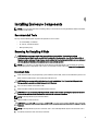
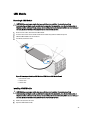
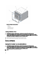
Removing And Installing A Blade...........................................................................................................................71
Removing A Blade............................................................................................................................................71
Installing A Blade.............................................................................................................................................73
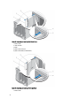
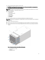
Removing And Installing A Sleeve..........................................................................................................................73
Removing The Sleeve.......................................................................................................................................73
Installing The Sleeve........................................................................................................................................74
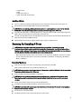
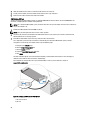
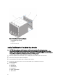
Power Supply Modules...........................................................................................................................................74
Power Supply Blanks.......................................................................................................................................75
Removing A Power Supply Module..................................................................................................................75
Installing a Power Supply Module...................................................................................................................77
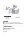
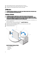
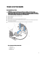
Fan Modules...........................................................................................................................................................77
Removing A Fan Module..................................................................................................................................78
Installing a Fan Module....................................................................................................................................78
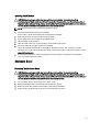
CMC Module...........................................................................................................................................................79
Removing A CMC Module................................................................................................................................79
Installing A CMC Module.................................................................................................................................79
iKVM Module..........................................................................................................................................................81
Removing An iKVM Module.............................................................................................................................81
Installing An iKVM Module...............................................................................................................................81
I/O Modules............................................................................................................................................................82
Removing An I/O Module.................................................................................................................................82
Installing An I/O Module...................................................................................................................................83
Enclosure Bezel......................................................................................................................................................83
Removing The Enclosure Bezel........................................................................................................................83
Installing The Enclosure Bezel.........................................................................................................................84
Enclosure Midplane................................................................................................................................................84
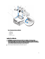
Removing The Front Module Cage Assembly And Midplane...........................................................................84
Installing The Midplane And Front Module Cage Assembly............................................................................86
Enclosure Control Panel Assembly.........................................................................................................................87
Removing The Control Panel............................................................................................................................87
Installing The Control Panel.............................................................................................................................88
LCD Module............................................................................................................................................................88
Removing The LCD Module..............................................................................................................................88
Installing The LCD Module...............................................................................................................................89
5 Troubleshooting The Enclosure..............................................................................................91
Safety First—For You and Your System..................................................................................................................91
Responding to a Systems Management Alert Message........................................................................................91
Troubleshooting A Damaged Enclosure.................................................................................................................91
Troubleshooting Enclosure Components................................................................................................................91
Troubleshooting A Wet Enclosure...................................................................................................................92
Troubleshooting Power Supply Modules.........................................................................................................92
Troubleshooting Fan Modules..........................................................................................................................93
Troubleshooting The iKVM Module.................................................................................................................93
Troubleshooting I/O Modules...........................................................................................................................93
6 Technical Specifications.........................................................................................................95
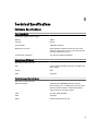
Enclosure Specifications........................................................................................................................................95
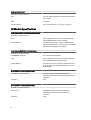
I/O Module Specifications......................................................................................................................................96
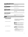
7 Getting Help................................................................................................................................99
Contacting Dell.......................................................................................................................................................99
About Your System
1
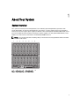
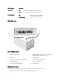
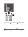
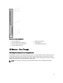
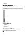
System Overview
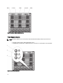
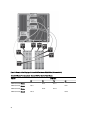
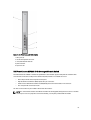
Your system can include up to 16 half-height blades (server modules), eight full-height blades, eight sleeves with
quarter-height blades, or a mix of the three blade types. To function as a system, a blade or sleeve is inserted into an
enclosure (chassis) that supports power supplies, fan modules, a Chassis Management Controller (CMC) module, and at
least one I/O module for external network connectivity. The power supplies, fans, CMC, optional iKVM module, and I/O
modules are shared resources of the blades in the PowerEdge M1000e enclosure.
NOTE: To ensure proper operation and cooling, all bays in the enclosure must be populated at all times with either
a module or with a blank.
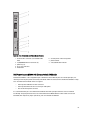
Figure 1. Blade Numbering – Half-Height Blades
7
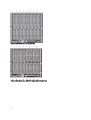
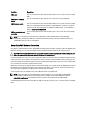
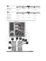
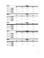
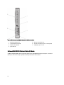
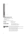
Figure 2. Blade Numbering – Full Height Blades
Figure 3. Blade Numbering – Mixed Full-Height and Half-Height Blades
8
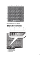
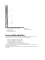
Figure 4. Blade Numbering – Quarter Height Blades
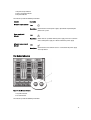
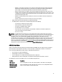
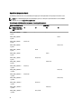
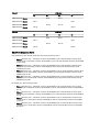
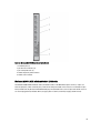
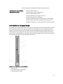
System Control-Panel Features
Figure 5. Control-Panel Features
1. USB port (mouse only)
2. USB port (keyboard only)
3. video connector
9
4. system power button
5. system power indicator
Control Panel
Features
Description
System power
button
Turns the system on and off. Press to turn on the system. Press and hold 10 seconds to turn off
the system.
NOTE: The system power button controls power to all of the blades and I/O modules in the
enclosure.
System power
indicator
Icon
Indicators
USB ports for
keyboard and
mouse
Off
System does not have power.
Green
System power is on.
Icon
Description
Functional if an optional iKVM module is installed and front panel ports are
enabled (default setting) in the CMC interface.
NOTE: These ports do not support USB storage devices. Only connect USB
storage devices to the USB ports on the front panel of the blade.
Video connector
Icon
Description
Functional if an optional iKVM module is installed and front panel ports are
enabled (default setting) in the CMC interface.
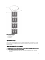
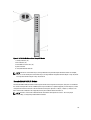
LCD Module
The LCD module provides an initial configuration/deployment wizard, as well as easy access to infrastructure and blade
information, and error reporting.
10
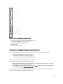
Figure 6. LCD Display
1. LCD screen
2. scroll buttons (4)
3. selection ("check") button
LCD Module Features
The primary function of the LCD module is to provide real-time information on the health and status of the modules in the
enclosure.
LCD module features include:
•
A deployment setup wizard that allows you to configure the CMC module’s network settings during initial system
set up.
•
Menus to configure the iDRAC in each blade.
•
Status information screens for each blade.
•
Status information screens for the modules installed in the back of the enclosure, including the I/O modules,
fans, CMC, iKVM, and power supplies.
•
A Network Summary screen listing the IP addresses of all components in the system.
•
Real time power consumption statistics, including high and low values, and average power consumption.
•
Ambient temperature values.
•
AC power information.
•
Critical failure alerts and warnings.
11
Using The LCD Module Menus
Key
Action
Left and right arrows
Move between screens.
Up or down arrow
Move to the previous or next option on a screen.
Center button
Select and save an item and move to the next screen.
Main Menu
The Main Menu options include links to the LCD Setup Menu, Server Menu, and Enclosure Menu.
LCD Setup Menu
You can change the default language and start-up screen for the LCD menu screens using this menu.
Server Menu
From the Server Menu dialog box, you can highlight each blade in the enclosure using the arrow keys, and view its
status.
•
A blade that is turned off or booting is designated by a gray rectangle. An active blade is indicated by a green
rectangle. If a blade has errors, this condition is indicated by an amber rectangle.
•
To select a blade, highlight it and press the center button. A dialog box displays the iDRAC IP address of the
blade and any errors present.
Enclosure Menu
The Enclosure Menu includes options for Module Status, Enclosure Status, and Network Summary.
•
In the Module Status dialog box, you can highlight each component in the enclosure and view its status.
–
A module that is turned off or booting is designated by a gray rectangle. An active module is indicated
by a green rectangle. If a module has errors, it is indicated by an amber rectangle.
–
If a module is selected, a dialog box displays the current status of the module and any errors present.
•
In the Enclosure Status dialog box, you can view the enclosure status, any error conditions, and power
consumption statistics.
•
The Network Summary screen lists the IP addresses for the CMC and iDRAC in each blade, and other
components in the enclosure.
Configuration Wizard
The CMC is preset for Dynamic Host Configuration Protocol (DHCP). To use a static IP address, you must toggle the CMC
setting from DHCP to a static address by either running the LCD configuration wizard, or by using a management station
and CLI commands. For more information, see the CMC documentation at support.dell.com/manuals.
To set up a network using the LCD configuration wizard:
1.
If you have not already done so, press the chassis power button to turn it on.
The LCD screen displays a series of initialization screens as it turns on. When it is ready, the Language Setup
screen is displayed.
2.
Select a language from the options in the dialog box.
The following message is displayed on the enclosure screen: Configure Enclosure?
3.
12
Press the center button to continue to the CMC Network Settings screen.
4.
5.
Configure the CMC network settings for your network environment:
–
Network speed
–
Duplex mode
–
Network mode (DHCP or static)
–
Static IP address, subnet mask, and gateway values (if static mode was selected)
–
DNS settings
If required, configure the iDRAC network settings. For more information about iDRAC, see the iDRAC User’s Guide
at support.dell.com/manuals.
NOTE: The configuration wizard automatically configures each blade’s iDRAC internal network interface if you do
not choose to manually configure the iDRAC settings.
NOTE: You cannot set a static IP address for the iDRAC using the LCD configuration wizard. To set a static IP
address, use the CMC web-based interface or Remote Access Controller Administrator (RACADM).
6.
Review the settings on the Network Summary screen:
–
If the settings are correct, press the center button to close the configuration wizard and return to the Main
Menu.
–
If the settings are not correct, use the left arrow key to return to the screen for that setting and correct it.
After you complete the configuration wizard, the CMC is available on your network.
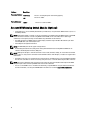
Back-Panel Features
Figure 7. Back-Panel Features
1. fan modules (9)
2. primary CMC module
3. I/O modules (6)
4. optional iKVM module
5. secondary CMC module
6. power supplies (6)
13
Figure 8. Back-Panel Module Bay Numbering
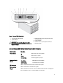
Power Supply Indicators
NOTE: The power supplies must be connected to a Power Distribution Unit (PDU), not directly to an electrical
outlet.
•
•
The power supplies require a 100 V to 240 V power source.
A 2700 W power supply provides 1350 W input power, if connected to a 110 V AC power source (optional).
Figure 9. Power Supply Indicators
14
1. DC power output indicator
2. power supply fault indicator
3. AC power indicator
The indicators provide the following information:
Indicator
Description
DC power output indicator
Icon
Description
Power supply fault
indicator
Icon
Description
AC power source present
indicator
Green indicates that the power supply is operational and providing DC
power to the system.
Amber indicates a problem with the power supply, which can result from
either a failed power supply or a failed fan within the power supply.
Icon
Description
Green indicates that a valid AC source is connected to the power supply
and is operational.
Fan Module Indicators
Figure 10. Fan Module Indicators
1. fan power indicator
2. fan fault indicator
The indicators provide the following information:
15
Indicator
Fan power indicator
Fan fault indicator
Description
Solid Green
The fan is receiving DC power and working properly.
Off
The fan has failed.
Amber
The fan is in a fault condition.
Avocent iKVM Analog Switch Module (Optional)
•
Local iKVM access can be remotely disabled on a per blade basis, using the blade’s iDRAC interface (access is
enabled by default).
NOTE: By default (enabled), a console session to a given blade is available for both the iDRAC interface and iKVM
(users connected to a blade's console using iDRAC and the iKVM see the same video and are able to type
commands). If not required, sharing can be disabled using the iDRAC console interface.
•
One VGA connector. The iKVM supports a video display resolution range from 640 x 480 at 60 Hz up to 1280 x
1024 x 65,000 colors (non-interlaced) at 75 Hz.
•
Two USB ports for keyboard and mouse.
NOTE: The iKVM USB ports do not support storage devices.
•
RJ-45 Analog Console Interface (ACI) port for tiering with Dell and Avocent analog KVM and KVM over IP
switches with Analog Rack Interface (ARI) ports.
NOTE: Although the ACI port is an RJ-45 connector and uses Cat5 (or better) cabling, it is not an Ethernet network
interface port. It is only used for connection to external KVM switches with ARI ports, and does not support native
KVM over IP.
•
The iKVM can also be accessed from the front of the enclosure, providing front or rear panel KVM functionality,
but not at the same time. For enhanced security, front panel access can be disabled using the CMC’s interface.
NOTE: Connecting a keyboard, video, and mouse to the enclosure front panel disables video output to the iKVM
back panel port. It does not interrupt iDRAC video and console redirection.
•
16
You can use the iKVM to access the CMC console directly, using RACADM or using the web-based interface.
For more information, see Using the iKVM Module in the CMC User’s Guide at support.dell.com/manuals.
Figure 11. Avocent iKVM Switch Module
1. status/identification indicator
2. power indicator
3. link indicator
CAUTION: Do not connect the ACI port to a LAN
device such as a network hub. Doing so may result in
equipment damage.
4. Analog Console Interface (ACI) port (for tiering
connection only)
5. activity indicator
6. USB connectors (2) for keyboard and mouse
7. video connector
Avocent Analog iKVM Switch Module Features And Indicators
Module Feature
Power indicator
Status/Identification
indicator
Description
Off
iKVM switch does not have power.
Green
iKVM switch has power.
Green flashing
Firmware upgrade in progress.
Blue blinking
iKVM module is being identified.
Amber flashing
System fault or error condition.
USB connectors
Allows a keyboard and mouse to be connected to the system.
Video connector
Allows a monitor to be connected to the system.
ACI port
Allows connection of one or more servers to a Dell console switch with an Analog Rack
Interface (ARI) port, such as an external digital or analog switch.
17
Module Feature
Description
Link indicator
Activity indicator
Off
The ACI is not connected to the external switch.
Green
The ACI is connected to the external switch.
Off
Data is not being sent or received.
Amber blinking
Data is being sent or received.
CMC Module
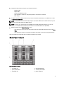
Figure 12. CMC Module Features
1
Ethernet connector Gb1
2
Ethernet connector STK ("stack") - used for daisychaining CMCs in separate enclosures
3
link indicator
4
activity indicator
5
DB-9 serial connector for local configuration
6
optional secondary CMC (CMC 2)
7
optional iKVM module
8
primary CMC (CMC 1)
9
blue status/identification indicator
10
power indicator
CMC Module Features
The CMC provides the following multiple systems management functions for your modular server:
•
18
Enclosure-level real-time automatic power and thermal management.
–
Monitors system power requirements and supports the optional Dynamic Power Supply Engagement
(DPSE) mode. The DPSE mode improves power efficiency by allowing the CMC to dynamically place
power supplies in standby mode, depending on the load and redundancy requirements.
–
Reports real-time power consumption, which includes logging high and low points with a time stamp.
–
Supports setting an optional enclosure Maximum Power Limit, which either alerts or takes actions, such
as throttling server modules and/or preventing the power up of new blades to keep the enclosure under
the defined maximum power limit.
–
Monitors and automatically controls cooling fans based on actual ambient and internal temperature
measurements.
–
Provides comprehensive enclosure inventory and status/error reporting.
•
CMC fail-safe mode. For more information, see CMC Fail-Safe Mode.
•
The CMC provides a mechanism for centralized configuration of the following:
–
The enclosure’s network and security settings
–
Power redundancy and power ceiling settings
–
I/O switches and iDRAC network settings
–
First boot device on the server blades
–
Checks I/O fabric consistency between the I/O modules and blades and disables components if
necessary to protect the system hardware
–
User access security
NOTE: It is recommended that you isolate chassis management from the data network. Dell cannot support or
guarantee uptime of a chassis that is improperly integrated into your environment. Due to the potential of traffic on
the data network, the management interfaces on the internal management network can be saturated by traffic
intended for servers. This results in CMC and iDRAC communication delays. These delays may cause
unpredictable chassis behavior, such as CMC displaying iDRAC as offline even when it is up and running, which in
turn causes other unwanted behavior. If physically isolating the management network is impractical, the other
option is to separate CMC and iDRAC traffic to a separate VLAN. The CMC and individual iDRAC network interfaces
can be configured to use a VLAN with the racadm setniccfg command. For more information, see the Dell Chassis
Management Controller Administrator Reference Guide at support.dell.com/manuals.
CMC Fail-Safe Mode
Similar to the failover protection offered by the redundant CMC, the M1000e enclosure enables the fail-safe mode to
protect the blades and I/O modules from failures. The fail-safe mode is enabled when no CMC is in control of the
chassis. During the CMC failover period or during a single CMC management loss:
•
you cannot turn on newly installed blades
•
existing blades cannot be accessed remotely
•
chassis cooling fans run at 100% for thermal protection of the components
•
blade performance reduces to limit power consumption until management of the CMC is restored
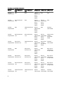
The following are some of the conditions that can result in CMC management loss:
Condition
Description
CMC removal
Chassis management resumes after replacing CMC, or after failover to standby CMC.
CMC network cable
removal or network
connection loss
Chassis management resumes after the chassis fails over to the standby CMC. Network
failover is only enabled in redundant CMC mode.
19
Condition
Description
CMC reset
Chassis management resumes after the CMC reboots or chassis fails over to the standby
CMC.
CMC failover command
issued
Chassis management resumes after the chassis fails over to the standby CMC.
CMC firmware update
Chassis management resumes after the CMC reboots or chassis fails over to the standby
CMC. It is recommended that you update the standby CMC first so that there is only one
failover event. For more information on updating the CMC firmware, see the CMC User's
Guide at support.dell.com/manuals.
CMC error detection and
correction
Chassis management resumes after the CMC resets or chassis fails over to the standby
CMC.
NOTE: You can configure the enclosure with a single CMC or with redundant CMCs. In redundant CMC
configurations, if the primary CMC loses communication with the enclosure or the management network, the
standby CMC takes over chassis management.
Daisy-Chain CMC Network Connection
Each CMC has two RJ-45 Ethernet ports, labeled GB (the uplink port) and STK (the stacking or cable consolidation port).
With basic cabling, you can connect the GB port to the management network and leave the STK port unused.
CAUTION: Connecting the STK port to the management network can have unpredictable results. Cabling GB and
STK to the same network (broadcast domain) can cause a broadcast storm.
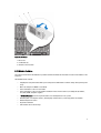
If you have multiple chassis in a rack, you can reduce the number of connections to the management network by daisychaining up to four chassis together. If each of the four chassis contains a redundant CMC, by daisy-chaining you can
reduce the number of management network connections required from eight to two. If each chassis has only one CMC,
you can reduce the connections required from four to one.
When daisy-chaining chassis together, GB is the uplink port and STK is the stacking (cable consolidation) port. Connect
the GB ports to the management network or to the STK port of the CMC in a chassis that is closer to the network. You
must connect the STK port only to a GB port further from the chain or network.
Create separate chains for the CMCs in the active CMC slot and the second CMC slot.
NOTE: At least one CMC must be installed for the system to power up. If a second, optional CMC module is
installed, failover protection and hot-swap replacement is available. See the latest CMC User's Guide at
support.dell.com/manuals for complete instructions on how to set up and operate the CMC module.
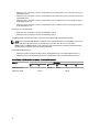
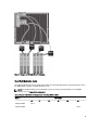
The following figure illustrates the arrangement of cables for four daisy-chained chassis, each with active and standby
CMCs.
20
Figure 13. CMC Daisy-Chaining
1. management network
2. secondary CMC
3. primary CMC
System Messages
System messages related to the blades in the enclosure may appear on the monitor screen to notify you of a possible
problem with a blade. For a detailed listing of these error messages, including possible causes and solutions, see the
blade documentation.
Other Information You May Need
WARNING: See the safety and regulatory information that shipped with your system. Warranty information may be
included within this document or as a separate document.
•
The Getting Started Guide provides an overview of system features, setting up your system, and technical
specifications.
21
•
The blade Owner's Manual provides information about the blade features and describes how to troubleshoot the
blade and install or replace the blade's components.
•
The Dell CMC User’s Guide provides information on installing, configuring, and using the CMC.
•
Dell systems management application documentation provides information about installing and using the
systems management software.
•
For the full name of an abbreviation or acronym used in this document, see the Glossary at support.dell.com/
manuals.
•
Any media that ships with your system that provides documentation and tools for configuring and managing your
system, including those pertaining to the operating system, system management software, system updates, and
system components that you purchased with your system.
NOTE: Always check for updates on support.dell.com/manuals and read the updates first because they often
supersede information in other documents.
22
Initial System Configuration
2
Before You Begin
CAUTION: The enclosure power supplies must be connected to a Type B or permanently-connected PDU and not
directly to an electrical outlet. The power supplies require a 100 V to 120 V or 200 V to 240 V power source. You can
select only one AC power input, as the system does not operate at both ranges simultaneously.
If your network uses static addressing, you need the IP address, subnet mask, and gateway to configure the CMC and
other modules in the enclosure.
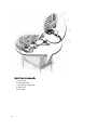
Initial Setup Sequence
NOTE: Follow the instructions on the enclosure chassis and remove the blades and power supplies before lifting
and installing the system. Reinstall the blades and power supplies after you install the chassis in the rack.
1.
Unpack the enclosure and install it in a rack.
For more information, see the Getting Started Guide and Rack Installation Guide at support.dell.com/manuals.
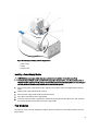
CAUTION: Do not turn on the blades (server modules) until you have configured the switch modules.
2.
Connect the power supply units to a PDU.
3.
If an optional iKVM module is installed, connect the keyboard, video, and mouse to the enclosure control panel or
to the iKVM module.
NOTE: Connecting a keyboard, video, and mouse to the enclosure control panel disables video output to the iKVM
back panel port.
4.
Press the power button on the enclosure control panel.
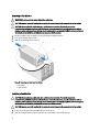
5.
Configure the CMC network settings.
The LCD configuration wizard allows you to quickly configure the CMC and iDRAC management interfaces and
manage the enclosure remotely. You can also use a management station and the RACADM CLI to configure the
CMC.
6.
Configure the I/O modules to allow proper network or storage management or paths.
7.
After the Ethernet and fibre channel switches are configured, you can turn on your server blades. This allows time
for the Ethernet switch to boot and allow PXI\UNDI traffic for all blade modules.
Initial CMC Network Configuration
The CMC is preset for DHCP. To use a static IP address, you must toggle the CMC setting from DHCP to a static address
by either running the LCD configuration wizard, or by using a management station and CLI commands.
If toggled to use a static address, the CMC IP address defaults to the standard IP address settings of 192.168.0.120,
255.255.255.0, and gateway of 192.168.0.1. You can change this address to an IP address of your choice.
23
Configuring The CMC Using The LCD Configuration Wizard
When you first boot your system, the screen on the LCD module directs you to configure the CMC network settings.
NOTE: The option to configure the enclosure using the LCD configuration wizard is only available until the CMC
default password is changed or when the LCD configuration wizard is complete. Thereafter, use the RACADM CLI
or the web-based GUI to change the CMC settings.
NOTE: The serial null modem cable for the CMC is an option. You can access the CLI using the 17th blade feature
on the embedded iKVM module. Blade number 17 is a direct local connection to the CMC.
1.
Choose a language from the options in the dialog box.
2.
Start the LCD configuration wizard.
3.
Configure the CMC network settings for your network environment.
–
Network speed
–
Duplex mode
–
Protocol (IPv4 and/or IPv6)
–
Network mode (DHCP or static)
–
Static IP address, subnet mask, and gateway values (if static mode was selected)
–
DNS setting, including a registered CMC name, (if DHCP mode was selected)
NOTE: The CMC external management network mode is set by default to DHCP. To use a static IP address, you
must change the setting using the LCD configuration wizard.
4.
If required, configure the iDRAC network setting for DHCP mode.
NOTE: You cannot set a static IP address for the iDRAC using the LCD configuration wizard. To set the static IP
address, use the web-based interface.
5.
Review the settings on the Network Summary screen:
–
If the settings are correct, press the center button to close the configuration wizard and return to the Main
Menu.
–
If the settings are not correct, use the left-arrow key to return to the screen for that setting and make the
appropriate changes.
The Network Summary screen lists the IP addresses for the CMC and the iDRAC network settings.
After you complete the LCD configuration wizard, you can access the CMC on the network using the web-based CMC
interface or text-based interfaces such as a serial console, Telnet, or SSH.
NOTE: If you want to use static addresses rather than DHCP to access the iDRACs, you must configure them using
the CMC web-based interface or CLI.
Configuring The CMC Using A Management Station And CLI
The LCD configuration wizard is the quickest way to initially configure the CMC network settings. However, you can also
use a management station and a local connection to access the CMC.
There are two ways to create a local connection to the CMC:
24
•
The CMC Console, using the optional iKVM. Press <Prnt Scrn> and select blade number 17.
•
Serial connection, using an optional null modem cable (115200 bps, 8 data bits, no parity, 1 stop bit, and no flow
control).
Once you have established a connection to the CMC, you can complete the initial CMC network configuration.
1.
Log in to the CMC.
The default user name is root and the default password is calvin.
2.
Type getniccfg and press <Enter> to view the current CMC network parameters.
3.
Configure the CMC network settings:
–
To set a static IP address, type
setniccfg -s <IP address><network mask><gateway>
and press <Enter>.
–
To configure the CMC to obtain an IP address using DHCP, type
setniccfg -d
and press <Enter>.
The new network settings are activated in a few seconds after configuring the network.
Logging In To The CMC Using The Web-Based Interface
1.
Open a supported web browser window.
2.
Log in to the CMC.
For current information on supported web browsers, see the CMC User’s Guide at support.dell.com/manuals.
–
If the CMC is accessed using a specific IP address, type the following URL in the Address field, and then
press <Enter>.
https://<CMC IP address>
The default IP address for the CMC is 192.168.0.120. If the default HTTPS port number (port 443) has been
changed, type:
https://<CMC IP address>:<port number>
where <CMC IP address> is the IP address for the CMC and <port number> is the HTTPS port number.
–
If you access the CMC using a registered DNS name, type the CMC’s name:
https://<CMC name>
By default, the CMC name on the DNS server is cmc-<service tag>
The CMC Login page is displayed.
NOTE: The default CMC user name is root, and the password is calvin. The root account is the default
administrative account that ships with the CMC. For added security, you must change the default password of the
root account during initial setup.
NOTE: The CMC does not support extended ASCII characters, such as ß, å, é, ü, or other characters used primarily
in non-English languages.
NOTE: You cannot log in to the web-based interface with different user names in multiple browser windows on a
single workstation.
You can log in as either a CMC user or as Directory Service user in Microsoft Active Directory or Lightweight
Directory Access Protocol Services (LDAP).
3.
In the Username field, type your user name:
–
CMC user name: <user name>
–
Active Directory user name: <domain>\<user name>
25
–
LDAP user name: <user name>
NOTE: This field is case sensitive.
4.
In the Password field, type your CMC user password or Active Directory user password.
NOTE: This field is case-sensitive.
Adding And Managing CMC Users
From the Users and User Configuration pages in the web-based interface, you can view information about CMC users,
add a new user, and change settings for an existing user.
NOTE: For added security, it is highly recommended that you change the default password of the root (User 1)
account. The root account is the default administrative account that ships with the CMC.
To change the default password for the root account, click User ID 1 to open the User Configuration page. Help for that
page is available through the Help link at the top right corner of the page.
NOTE: You must have User Configuration Administrator privileges to perform the following steps.
1.
Log in to the web-based interface.
2.
Select Chassis in the system tree.
3.
Click the Network/Security tab, and then click the Users sub-tab.
The Users page is displayed, listing each user’s user ID, login state, user name, and CMC privilege, including those
of the root user. User IDs available for configuration have no user information displayed.
4.
Click an available user ID number. The User Configuration page is displayed.
To refresh the contents of the Users page, click Refresh. To print the contents of the Users page, click Print.
5.
Select general settings for the users.
For details on user groups and privileges, see the CMC User’s Guide at support.dell.com/manuals.
6.
Assign the user to a CMC user group.
You can customize the privileges settings for the user by using the check boxes. After you have selected a CMC
Group or made Custom user privilege selections, click Apply Changes to save the settings.
When you select a user privilege setting from the CMC Group drop-down menu, the enabled privileges (shown as
checked boxes in the list) are displayed according to the pre-defined settings for that group.
Configuring iDRAC Networking Using The Web-Based Interface
Follow this procedure to configure the iDRAC in the LCD configuration wizard.
NOTE: If you did not configure the iDRAC using the LCD configuration wizard, iDRAC is disabled until you configure
it using the web-based interface.
NOTE: You must have Chassis Configuration Administrator privileges to set up iDRAC network settings from the
CMC.
NOTE: The default CMC user name is root and the default password is calvin.
1.
Log in to the web-based interface.
2.
Click the plus (+) symbol next to Chassis in the left column, then click Servers.
3.
Click Setup → Deploy.
4.
Select the protocol for the iDRAC setting (IPv4 and/or IPv6).
5.
Under Enable Lan, select the check box next to the server to enable LAN for iDRAC.
26
6.
Under Enable IPMI over LAN, select or clear the check box next to the server to enable or disable IPMI over LAN.
7.
Under DHCP Enabled, select or clear the check box next to the server to enable or disable DHCP for iDRAC.
8.
If DHCP is disabled, enter the static IP address, netmask, and default gateway for the iDRAC.
9.
Click Apply at the bottom of the page.
Setting The First Boot Device For Servers
The First Boot Device page allows you to specify the boot device for each blade. You can set the default boot device and
also set a one-time boot device. This allows you to boot using a special image to perform tasks such as running
diagnostics or reinstalling an operating system.
To set the first boot device for some or all servers in the chassis:
1.
Log in to the CMC web-based interface.
2.
Click Servers in the system tree and then click Setup → Deploy First Boot Device. A list of servers is displayed, one
per row.
3.
Select the boot device you want to use for each server from the list box.
4.
If you want the server to boot from the selected device every time it boots, clear the Boot Once check box for the
server.
If you want the server to boot from the selected device only on the next boot cycle, select the Boot Once check box
for the server.
5.
Click Apply.
Configuring And Managing Power
You can use the web-based and RACADM interfaces to manage and configure power controls on the CMC, as outlined
in the following sections. For more information on the various power management options, see the CMC User’s Guide at
support.dell.com/manuals.
The CMC’s power management service optimizes power consumption for the entire chassis (the chassis, servers, I/O
modules, iKVM, CMC, and PSUs) and re-allocates power to different modules based on the demand.
NOTE: To perform power management actions, you must have Chassis Control Administrator privileges.
1.
Log in to the CMC web-based interface.
2.
Select Chassis in the system tree.
3.
Click the Power Management tab. The Power Budget Status page is displayed.
4.
Click the Configuration sub-tab. The Budget/Redundancy Configuration page is displayed.
5.
Configure the power budget and redundancy settings based on the components in the enclosure and your needs.
6.
Click Apply to save your changes.
Installing Or Updating The CMC Firmware
NOTE: It is normal for some or all of the fan units to spin at 100 percent during CMC or iDRAC firmware updates on
a server.
NOTE: In a redundant CMC configuration, care must be taken to update CMC firmware on both modules. Failure to
do so may cause unexpected behavior during a CMC failover or failback. Use the following procedure for
redundant CMC deployments.
27
1.
Locate the secondary or standby CMC by using the RACADM getsysinfo command, or by using the Chassis
Summary page in the web-based interface. Visually, the status indicator is solid blue on the primary or active CMC
module and off on the standby or secondary CMC.
2.
Update the firmware on the standby CMC first, using the web-based interface or RACADM.
3.
Verify that the secondary or standby CMC’s firmware is at the requested level with the getsysinfo command or
using the web-based interface.
4.
After the standby CMC has rebooted, update the firmware on the active or primary CMC. Allow 10 minutes for the
standby CMC to boot.
5.
Verify that the active or primary CMC firmware is at the requested level using the getsysinfo command or using
the web-based interface.
6.
Once both CMCs are updated to the same firmware revision, use the cmcchangeover command to reset the
CMC in the left slot as primary.
Downloading The CMC Firmware
Before beginning the firmware update, download the latest firmware version from support.dell.com, and save it to your
local system. The following software components are included with your CMC firmware package:
•
Compiled CMC firmware code and data
•
Web-based interface, JPEG, and other user interface data files
•
Default configuration files
Use the Firmware Update page to update the CMC firmware to the latest revision. When you run the firmware update,
the update retains the current CMC settings.
NOTE: The firmware update, by default, retains the current CMC settings. During the update process, you have the
option to reset the CMC configuration settings back to the factory default settings.
Updating The CMC Firmware Using The Web-Based Interface
1.
Log in to the web-based interface.
2.
Click Chassis in the system tree.
3.
Click the Update tab. The Updatable Components page is displayed.
4.
On the Updatable Components page, click the CMC name. The Firmware Update page is displayed.
5.
In the Value field, type the path on your management station or shared network where the firmware image file
resides, or click Browse to navigate to the file location.
NOTE: The default CMC firmware image name is firmimg.cmc and this filename must not be changed. Ensure that
you keep different firmware revisions separated as the file name always remains the same.
6.
Click Update. A dialog box prompts to confirm the action.
7.
Click Yes to continue. The firmware transfer process begins and the status displays the message Firmware
Update in Progress. After the CMC update is complete, the CMC is reset and you must refresh the User
Interface page to log in again.
Updating The CMC Firmware Using RACADM
1.
Open a CMC command line console and log in.
2.
Type:
racadm fwupdate -g -u - a <TFTP server IP address> -d <filepath> -m <cmcactive|cmc-standby>
28
For complete instructions on how to configure and operate the CMC module, see the latest CMC User's Guide at
support.dell.com/manuals.
Configuring The Optional iKVM Switch Module
Updating The iKVM Firmware
NOTE: The iKVM resets and becomes temporarily unavailable after the firmware has been uploaded successfully.
1.
Log in to the CMC web-based interface.
2.
Select Chassis in the system tree.
3.
Click the Update tab. The Updatable Components page is displayed.
4.
Click the iKVM name. The Firmware Update page is displayed.
5.
In the Value field, type the path on your management station or shared network where the firmware image file
resides, or click Browse to navigate to the file location.
NOTE: The default iKVM firmware image name is ikvm.bin. However, the iKVM firmware image name can be
renamed. If you are unable to locate ikvm.bin, verify if another user has renamed the file.
6.
Click Update. A dialog box prompts you to confirm the action.
7.
Click Yes to continue.
When the update is complete, the iKVM resets.
Tiering The Avocent iKVM Switch From A Digital KVM Switch
The iKVM module may also be tiered from a digital KVM switch such as the Dell 2161DS-2 or 4161DS, or a supported
Avocent digital KVM switch. Many switches may be tiered without the need for a Server Interface Pod (SIP).
The cabling requirements for various external digital KVM switches are as follows:
•
Dell PowerConnect 2161DS, 4161DS, 2161DS-2, 2321DS (version 1.3.40.0 or later) or Avocent DSR x02x (except
1024), x03x (version 3.6 or later): Seamless tiering using ACI port and Cat 5 cable
•
Avocent DSR 800, x16x, x010, 1024: Avocent USB SIP (DSRIQ-USB) with Cat 5 cable
To tier the iKVM module from a Dell 2161DS, 180AS, or 2160AS console switch:
•
•
If the switch does not require a SIP to connect to the iKVM , connect a Cat 5 (or newer) cable to the RJ-45 ACI
port on the iKVM module. Connect the other end of this cable to the ARI port on the external switch.
If the switch requires a USB SIP, connect an Avocent USB SIP to the iKVM, then connect a Cat 5 (or newer)
cable to the SIP. Connect the other end of this cable to the ARI port on the external switch.
Once the KVM switch is connected, the server modules are displayed in OSCAR.
NOTE: You must also re-synchronize the server list from the Remote Console Switch software to view the list of
blades.
Tiering The Avocent iKVM Switch From An Analog KVM Switch
The Avocent iKVM switch can be tiered from analog KVM switches such as the Dell 2160AS and 180AS, as well as many
Avocent analog KVM switches. Many switches may be tiered without the need for a SIP.
The cabling requirements for specific external switches are as follows:
29
•
Dell PowerConnect 180AS, 2160AS (version 1.0.3.2 or later) or Avocent Autoview 2020, 2030 (version 1.6.0.4 or
later): Seamless tiering using ACI port and Cat 5 cable
•
Avocent Autoview 1400, 1500, 2000, 1415, 1515, 2015u: Avocent USB SIP (DSRIQ-USB) required with Cat 5 cable
Before connecting the iKVM switch to a supported analog switch, you must set the display in slot order, and set the
Screen Delay Time to 1 or more seconds:
1.
Press <Prnt Scrn> to launch the iKVM Switch OSCAR.
2.
Click Setup → Menu. The Menu dialog box is displayed.
3.
Select Slot to display servers numerically by slot number.
4.
Set a screen delay time of at least 1 second.
5.
Click OK.
Setting the Screen Delay time to 1 second allows you to soft switch to a server without launching OSCAR.
NOTE: Soft switching allows you to switch servers using a hot key sequence. To soft switch to a server, press
<Prnt Scrn> and type the first few characters of its name or number. If you have a Delay Time set and you press
the key sequences before that time has elapsed, OSCAR does not display.
Configuring The Analog Switch
1.
Press <Prnt Scrn> to launch the iKVM Switch OSCAR.
2.
Click Setup → Devices → Device Modify.
3.
Select the 16-port option to match the number of blades in your system.
4.
Click OK to exit OSCAR.
5.
Press <Prnt Scrn> to verify that the settings have taken effect. The slot number of the blade to which the iKVM
switch is now attached must be expanded to display each of the slot locations of the blades in the system. For
instance, if the iKVM switch is attached to slot 1, it must be displayed as 01-01 to 01-16.
6.
Connect the Avocent iKVM switch to a supported analog switch:
If the switch does not require a SIP to connect to the iKVM, connect a Cat 5 (or newer) cable to the RJ-45 ACI port
on the iKVM module. Connect the other end of this cable to the ARI port on the external switch.
If the analog switch requires a USB SIP, connect an Avocent USB SIP to the iKVM, then connect a Cat 5 (or newer)
cable to the SIP. Connect the other end of this cable to the ARI port on the external switch.
7.
Connect both the analog switch and the system to an appropriate power source.
8.
Turn on the system.
9.
Turn on the external analog switch.
NOTE: If the external analog switch is powered up before the system, it may result in only one blade being
displayed in the analog switch OSCAR, instead of 16. If this behavior occurs, shut down and restart the switch so
that the entire complement of blades is recognized.
NOTE: In addition to the steps outlined above, some external analog switches may require you to perform
additional steps to ensure that the iKVM switch blades are displayed in the external analog switch OSCAR. For
more information, see the external analog switch documentation.
30
Resynchronizing The Server List At The Remote Client Workstation
Once the iKVM module is connected, the blades are displayed in OSCAR. You must re-synchronize the servers on any
remote workstation to ensure that the blades are available to any remote users connected to the console switch through
the Remote Console Switch software.
NOTE: This procedure only re-synchronizes one remote client workstation. With multiple client workstations, save
the re-synchronized local database and load it into the other client workstations to ensure consistency.
To re-synchronize the server listing:
1.
Click Resync in the Server category of the Management panel. The resync wizard launches.
2.
Click Next. A warning message is displayed indicating that the database will be updated to match the current
configuration of the console switch. Your current local database names will be overwritten with the switch names.
To include unpowered SIPs in the re-synchronization, select the Include Offline SIPs check box.
3.
Click Next. A Polling Remote Console Switch message box is displayed with a progress bar indicating that the
switch information is being retrieved.
4.
If no changes were detected in the appliance, a completion dialog box is displayed with this information. If server
changes were detected, then the Detected Changes dialog box is displayed.
5.
Click Next to update the database.
If a cascade switch was detected, the Enter Cascade Switch Information dialog box is displayed.
6.
Select the type of switch connected to the appliance from the drop-down list. If the type you are looking for is not
available, you can add it by clicking Add.
7.
Click Next. The completion dialog box is displayed.
8.
Click Finish to exit.
9.
Start up the analog switch and the system.
Viewing And Selecting Servers
Use the OSCAR Main dialog box to view, configure, and manage servers in the M1000e enclosure through the iKVM. You
can view the servers by name or by slot. The slot number is the chassis slot number the server occupies. The Slot
column indicates the slot number in which a server is installed.
NOTE: Server names and slot numbers are assigned by the CMC.
NOTE: If you have enabled access to the CMC though the iKVM, an additional option, Dell CMC Console, is
displayed.
To access the Main dialog box, press <Prnt Scrn> launch the iKVM Switch OSCAR. The Main dialog box is displayed.
or
If a password has been assigned, the Password dialog box is displayed. Type your password and click OK. The Main
dialog box is displayed.
To toggle between quarter-height blades installed in a sleeve:
1.
Press <Prnt Scrn> to launch the iKVM Switch OSCAR.
2.
Select the slot where the sleeve and blade is installed and press <Enter> to exit OSCAR.
3.
Press <Scroll Lock> twice to toggle between the quarter-height blades installed in the sleeve.
31
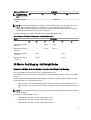
FlexAddress
The FlexAddress feature allows server modules to replace the factory assigned World Wide Name and Media Access
Control (WWN/MAC) network IDs with WWN/MAC IDs provided by the chassis. FlexAddress is delivered on a Secure
Digital (SD) card that must be inserted into the CMC to provide the chassis-assigned WWN/MAC IDs.
Every server module is assigned unique WWN and MAC IDs as part of the manufacturing process. Before the
FlexAddress feature was introduced, if you had to replace one server module with another, the WWN/MAC IDs would
change and Ethernet network management tools and SAN resources would need to be reconfigured to be aware of the
new server module.
FlexAddress allows the CMC to assign WWN/MAC IDs to a particular slot and override the factory IDs. If the server
module is replaced, the slot-based WWN/MAC ID remains the same. This feature eliminates the need to reconfigure
Ethernet network management tools and SAN resources for a new server module.
Additionally, the override action only occurs when a server module is inserted in a FlexAddress enabled chassis; no
permanent changes are made to the server module. If a server module is moved to a chassis that does not support
FlexAddress, the factory assigned WWN/MAC IDs are used.
Prior to installing FlexAddress, you can determine the range of MAC addresses contained on a FlexAddress feature card
by inserting the SD card into an USB Memory Card Reader and viewing the file pwwn_mac.xml. This clear text XML file
on the SD card contains an XML tag mac_start, which is the first starting hex MAC address that will be used for this
unique MAC address range. The mac_count tag is the total number of MAC addresses that the SD card allocates. The
total MAC range allocated can be determined by:
<mac_start> + 0xCF (208 - 1) = mac_end
For example:
(starting_mac)00188BFFDCFA + 0xCF =
(ending_mac)00188BFFDDC9
NOTE: To prevent modifying any of the contents accidentally, you must lock the SD card prior to inserting in the
USB "Memory Card Reader". You must then unlock the SD card before inserting it into the CMC.
For more information on the FlexAddress feature, see the following resources:
•
The CMC Secure Digital (SD) Card Technical Specification document at support.dell.com/manuals
•
The Help link in the CMC web interface
•
The FlexAddress information in the CMC User’s Guide at support.dell.com/manuals
FlexAddress Plus
FlexAddress Plus expands the number of MAC addresses to 3136 from the original FlexAddress pool of 208.
FlexAddress Plus is provided on the FlexAddress Plus Secure Digital (SD) card along with the FlexAddress feature.
NOTE: The SD card labeled FlexAddress only contains FlexAddress and the card labeled FlexAddress Plus contains
FlexAddress and FlexAddress Plus. The card must be inserted into the CMC to activate the feature.
32
Configuring The I/O Modules
3
Network Information
You can configure your I/O switch modules using:
•
CMC web-based interface.
NOTE: The default IP address for the CMC is 192.168.0.120.
•
CMC CLI using serial console redirection.
•
Direct access to the I/O module serial port (if supported).
•
I/O module default IP address (if supported).
I/O Connectivity
The enclosure supports three layers of I/O fabric, selectable between combinations of Ethernet, fibre-channel, and
Infiniband modules. You can install up to six hot-swappable I/O modules in the enclosure, including fibre channel
switches, fibre-channel pass-throughs, Infiniband switches, Ethernet switches, and Ethernet pass-through modules.
General I/O Module Configuration Guidelines
•
If an I/O module is installed in Fabric B or Fabric C, at least one blade must have a matching mezzanine card
installed to support data flow to that I/O module.
•
If a blade has an optional mezzanine card installed in a Fabric B or Fabric C card slot, at least one corresponding
I/O module must be installed to support data flow to that fabric.
•
Modules may be installed in Fabrics B and C independently (you do not need to install modules in Fabric B
before installing modules in the Fabric C slots).
•
Slots A1 and A2 only support Ethernet I/O modules. This fabric type is hardset to Ethernet for these slots and
cannot support fibre channel, Infiniband, or other fabric type modules.
•
Fabrics A, B, and C can support Ethernet fabric-type modules.
•
To enable switch configuration prior to blade imaging, I/O modules are allowed to power-up before a blade is
inserted in the enclosure.
Fabric A
Fabric A is a redundant Gb Ethernet fabric, supporting I/O module slots A1 and A2. The integrated Ethernet controllers in
each blade dictate Fabric A as an Ethernet-only fabric.
NOTE: Fabric A supports KR (10 Gbps standard).
NOTE: Modules designed specifically for Fabric B or Fabric C cannot be installed in slots A1 or A2, as indicated by
the color-coded labeling on the faceplate of each module.
33
Fabric B
Fabric B is a 1 to 40 Gb/sec redundant fabric, supporting I/O module slots B1 and B2. Fabric B currently supports 1 Gb or
10 Gb Ethernet, DDR/QDR Infiniband, and 4 Gbps or 8 Gbps fibre channel modules. Additional fabric types may be
supported in the future.
NOTE: Fabric B supports up to 16 Gbps fibre channel, Infiniband FDR (14 Gbps standard), and KR (10 Gbps
standard).
To communicate with an I/O module in the Fabric B slots, a blade must have a matching mezzanine card installed in a
Fabric B mezzanine card location.
Modules designed for Fabric A may also be installed in the Fabric B slots.
Fabric C
Fabric C is a 1 to 40 Gb/sec redundant fabric, supporting I/O module slots C1 and C2. Fabric C currently supports 1 Gb or
10 Gb Ethernet, DDR/QDR Infiniband, and 4 Gbps or 8 Gbps fibre channel modules. Additional fabric types may be
supported in the future.
NOTE: Fabric C supports up to 16 Gbps fibre channel, Infiniband FDR (14 Gbps standard), and KR (10 Gbps
standard).
To communicate with an I/O module in the Fabric C slots, a blade must have a matching mezzanine card installed in a
Fabric C mezzanine card location.
Modules designed for Fabric A may also be installed in the Fabric C slots.
Port Auto-Disablement in Quad-Port Network Daughter Card (Dell
PowerEdge M710HD Only)
Systems installed with quad-port Network Daughter Card support a Port Auto-Disablement feature. This feature disables
the third (NIC3) and fourth (NIC4) ports of a quad-port network daughter card during system boot, if the corresponding
I/O module installed in the chassis Fabric A slots does not support quad-port mapping. This behavior is limited to Fabric
A slots only and is automatically enabled or disabled depending on the type of I/O module installed.
NOTE: A quad-port network daughter card must be used with a 48-port switch module (32 internal ports) for all the
ports to be active.
NOTE: LOM firmware updates are applied only to the enabled ports on a quad-port network daughter card.
The following table provides an overview of the configurations that enable or disable the NIC3 and NIC4 ports of a quadport network daughter card.
Table 1. Port Auto-Disablement Decision Table
IOM Slot A1
IOM Slot A2
NIC3 and NIC4 (Enabled/
Disabled)
Port Auto-Disablement
Empty
Empty
Enabled
Inactive
Empty
Dual Port
Disabled
Active
Empty
Quad or Greater Port
Enabled
Inactive
Dual Port
Empty
Disabled
Active
34
IOM Slot A1
IOM Slot A2
NIC3 and NIC4 (Enabled/
Disabled)
Port Auto-Disablement
Dual Port
Dual Port
Disabled
Active
Dual Port
Quad or Greater Port
Enabled
Inactive
Quad or Greater Port
Empty
Enabled
Inactive
Quad or Greater Port
Dual Port
Enabled
Inactive
Quad or Greater Port
Quad or Greater Port
Enabled
Inactive
Mezzanine Cards
PowerEdge M610x Only
PowerEdge M610x supports two mezzanine cards. Mezzanine cards can be installed in both the slots on the midplane
interface card.
NOTE: PowerEdge M610x is a full-height blade but supports only two mezzanine cards in the expansion bay. The
two mezzanine slots on the M610x system board (MEZZ2_FAB_B and MEZZ1_FAB_C) are reserved for the
mezzanine interface card.
Full-Height Blades
Full-height blades support four mezzanine cards:
•
Slot Mezz1_Fabric_C and slot Mezz3_Fabric_C support Fabric C. They must match the fabric type of the I/O
modules installed in I/O module slots C1 and C2.
•
Slot Mezz2_Fabric_B and slot Mezz4_Fabric_B support Fabric B. They must match the fabric type of the I/O
modules installed in I/O module slots B1 and B2.
Half-Height Blades
Half-height blades support two mezzanine cards:
•
Mezzanine card slot C supports Fabric C. This card must match the fabric type of I/O modules installed in I/O
module slots C1 and C2.
•
Mezzanine card slot B supports Fabric B. This card must match the fabric type of I/O modules installed in I/O
module slots B1 and B2.
The following table shows various supported combinations of mezzanine cards and I/O modules.
35
Table 2. Supported I/O Module Configurations
Fabric A
Fabric C Mezzanine
Card
I/O Bay A1, A2
Standard
None
Integrated LOM
None
Ethernet
None
switch module
or passthrough
module
Standard
Ethernet mezzanine
Integrated LOM card
None
Ethernet
switch module
or passthrough
module
Standard
None
Integrated LOM
Infiniband mezzanine
card
Ethernet
None
switch module
or passthrough
module
Infiniband
switch module
Standard
Ethernet mezzanine
Integrated LOM card
Ethernet mezzanine
card
Ethernet
switch module
or passthrough
module
Ethernet
switch module
or passthrough
module
Ethernet switch
module or
pass-through
module
Standard
Fibre channel
Integrated LOM mezzanine card
Infiniband mezzanine
card
Ethernet
switch module
or passthrough
module
Fibre channel
switch or
pass-through
module
Infiniband
switch module
Standard
None
Integrated LOM
Fibre channel
mezzanine card
Ethernet
None
switch module
or passthrough
module
Standard
Fibre channel
Integrated LOM mezzanine card
Fibre channel
mezzanine card
Ethernet
switch module
or passthrough
module
Ethernet
Fibre channel
switch module switch or passor passthrough module
through
module
Standard
Ethernet mezzanine
Integrated LOM card
Fibre channel
mezzanine card
Ethernet
switch module
or passthrough
module
Ethernet
Fibre channel
switch module switch or passor passthrough module
through
module
Standard
Infiniband mezzanine
Integrated LOM card
Infiniband mezzanine
card
Ethernet
Infiniband
Infiniband
switch module switch module switch module
36
Fabric B Mezzanine
Card
I/O Bay B1, B2
I/O Bay C1, C2
None
Ethernet
None
switch module
or passthrough
module
Fibre channel
switch or passthrough module
Fabric A
Fabric B Mezzanine
Card
Fabric C Mezzanine
Card
I/O Bay A1, A2
I/O Bay B1, B2
I/O Bay C1, C2
or passthrough
module
Standard
Infiniband mezzanine
Integrated LOM card
Ethernet mezzanine
card
Ethernet
Infiniband
switch module switch module
or passthrough
module
Ethernet switch
module or
pass-through
module
Standard
Fibre channel
Integrated LOM mezzanine card
Ethernet mezzanine
card
Ethernet
switch module
or passthrough
module
Ethernet switch
module or
pass-through
module
Fibre channel
switch or
pass-through
module
Quarter-Height Blades
A quarter-height blade supports one mezzanine card. The mezzanine card slot supports Fabric B or Fabric C, depending
on the slot in the sleeve where the blade is installed.
I/O Module Port Mapping—Full-Height Blades
NOTE: The I/O port mappings in the following sections are applicable only to the I/O Pass-Through Modules.
Standard LOM (Dual-Port) Mapping
Each LOM has two port connections. For a full-height blade in bay n:
•
•
•
•
Integrated LOM1, connection 1 connects to I/O module A1, port n.
Integrated LOM1, connection 2 connects to I/O module A2, port n.
Integrated LOM2, connection 1 connects to I/O module A1, port n+8.
Integrated LOM2, connection 2 connects to I/O module A2, port n+8.
For example, in a full-height blade in slot 5:
•
•
•
•
Integrated LOM1 connection 1 connects to I/O module A1, port 5.
Integrated LOM1 connection 2 connects to I/O module A2, port 5.
Integrated LOM2 connection 1 connects to I/O module A1, port 13.
Integrated LOM2 connection 2 connects to I/O module A2, port 13.
NOTE: Even though PowerEdge M610x is a full-height blade system, only one network controller (LOM1) is
available.
For PowerEdge M610x blade in bay n, the integrated NIC connects to I/O module A1, port n and I/O module A2, port n.
Dual-Port Mezzanine Cards
Each mezzanine card has two port connections. For a full-height blade in bay n:
37
•
Mezzanine card 1, connection 1 connects to I/O module C1, port n. Mezzanine card 1, connection 2 connects to
I/O module C2, port n.
•
Mezzanine card 2, connection 1 connects to I/O module B1, port n. Mezzanine card 2, connection 2 connects to
I/O module B2 port n.
•
Mezzanine card 3, connection 1 connects to I/O module C1, port n+8. Mezzanine card 3, connection 2 connects
to I/O module C2 port n+8.
•
Mezzanine card 4, connection 1 connects to I/O module B1, port n+8. Mezzanine card 4, connection 2 connects
to I/O module B2 port n+8.
For example, in a full-height blade:
•
Mezzanine card 3 connection 1 connects to I/O module C1, port 13.
•
Mezzanine card 3 connection 2 connects to I/O module C2 port 13.
The following table shows the port number assignments for the eight possible full height blade locations.
NOTE: Even though PowerEdge M610x is a full blade system, only two mezzanine card slots (MEZZ1_FAB_C1 and
MEZZ2_FAB_B1) in the expansion bay are available for use. The other two slots on the system board
(MEZZ1_FAB_C and MEZZ2_FAB_B) are occupied by the mezzanine interface card which provides connectivity
between the PCIe expansion-card riser and the system board.
For PowerEdge M610x, in bay n:
•
Mezzanine card B (in the expansion bay) connects to I/O module B1, port n+8 and I/O module B2, port n+8.
•
Mezzanine card C (in the expansion bay) connects to I/O module C1, port n+8 and I/O module C2, port n+8.
Table 3. Example of I/O Module Port Assignments - PowerEdge M610x in Slot 2
Blade 2
I/O Module
A1
B1
Mezzanine Card C
Mezzanine Card B
38
Port 10
C1
C2
Port 10
Port 10
B2
Port 10
A2
Figure 14. Example of PowerEdge M610x Port Mapping – Blade 2
Table 4. I/O Module Port Assignments - Full-Height Blades (not applicable for PowerEdge M610x)
Blade 1
I/O Module
B1
Mezz1_Fab_C
Mezz2_Fab_B
C2
Port 1
Port 1
Port 1
Mezz3_Fab_C
Mezz4_Fab_B
C1
Port 1
Port 9
Port 9
Port 9
Port 9
Blade 2
I/O Module
B1
Mezz1_Fab_C
Mezz2_Fab_B
B2
Port 2
C1
C2
Port 2
Port 2
B2
Port 2
39
Blade 2
I/O Module
B1
Mezz3_Fab_C
Mezz4_Fab_B
C1
C2
Port 10
Port 10
Port 10
Port 10
Blade 3
I/O Module
B1
Mezz1_Fab_C
Mezz2_Fab_B
C1
C2
Port 3
Port 3
Port 3
Mezz3_Fab_C
Mezz4_Fab_B
Port 11
Port 11
I/O Module
Mezz1_Fab_C
C1
C2
Port 4
Port 4
Port 4
Mezz3_Fab_C
Port 12
Port 12
I/O Module
Mezz1_Fab_C
C1
C2
Port 5
Port 5
Port 5
Mezz3_Fab_C
Port 13
Port 13
I/O Module
Mezz1_Fab_C
C1
C2
Port 6
Port 6
Port 6
Mezz3_Fab_C
Port 14
Port 14
Port 14
Port 14
I/O Module
B1
Mezz1_Fab_C
40
B2
Port 6
Blade 7
Mezz2_Fab_B
Port 13
Port 13
B1
Mezz4_Fab_B
B2
Port 5
Blade 6
Mezz2_Fab_B
Port 12
Port 12
B1
Mezz4_Fab_B
B2
Port 4
Blade 5
Mezz2_Fab_B
Port 11
Port 11
B1
Mezz4_Fab_B
B2
Port 3
Blade 4
Mezz2_Fab_B
B2
Port 7
C1
C2
Port 7
Port 7
B2
Port 7
Blade 7
I/O Module
B1
Mezz3_Fab_C
Mezz4_Fab_B
C1
C2
Port 15
Port 15
Port 15
Port 15
Blade 8
I/O Module
B1
Mezz1_Fab_C
Mezz2_Fab_B
C1
C2
Port 8
Port 8
Port 8
Mezz3_Fab_C
Mezz4_Fab_B
B2
B2
Port 8
Port 16
Port 16
Port 16
Port 16
The following figure shows the port connections for a full-height blade in bay 3 with four mezzanine cards.
Figure 15. Example of Full-Height Blade Port Mapping – Blade 3 (not applicable for PowerEdge M610x)
41
Quad-Port Mezzanine Cards
The following table illustrates the I/O module port mapping for full-height blades with quad-port mezzanine cards.
NOTE: For a detailed mapping of each PowerEdge system, see Quadport Capable Hardware for the M1000e
Modular Chassis at support.dell.com/manuals.
Table 5. Example of I/O Module Port Assignments - PowerEdge M610x in Slot 2
Blade n and Blade (n + 8)
NOTE: n denotes a
variable value from 1
to 8.
Mezz_FAB_B_Blade
n_Port1
I/O Module
B1
C1
C2
Portn
Portn
Mezz_FAB_B_Blade
n_Port2
Mezz_FAB_B_Blade
n_Port3
Port(n+16)
Port(n+16)
Mezz_FAB_B_Blade
n_Port4
Portn
Mezz_FAB_C_Blade
n_Port1
Portn
Mezz_FAB_C_Blade
n_Port2
Port(n+16)
Mezz_FAB_C_Blade
n_Port3
Port(n+16)
Mezz_FAB_C_Blade
n_Port4
Mezz_FAB_B_Blade n
+8_Port1
Port(n+8)
Port(n+8)
Mezz_FAB_B_Blade n
+8_Port2
Mezz_FAB_B_Blade n
+8_Port3
Port(n+24)
Port(n+24)
Mezz_FAB_B_Blade n
+8_Port4
Mezz_FAB_C_Blade n
+8_Port1
Port(n+8)
Port(n+8)
Mezz_FAB_C_Blade n
+8_Port2
Mezz_FAB_C_Blade n
+8_Port3
42
B2
Port (n+24)
Blade n and Blade (n + 8)
NOTE: n denotes a
variable value from 1
to 8.
I/O Module
B1
C1
C2
B2
Port(n+24)
Mezz_FAB_C_Blade n
+8_Port4
NOTE: Even though PowerEdge M610x is a full blade system, only two mezzanine card slots (MEZZ1_Fab_C1 and
MEZZ2_FAB_B1) in the expansion bay are available for use. The other two slots on the system board
(MEZZ1_FAB_C and MEZZ2_FAB_B) are occupied by the mezzanine interface card which provides connectivity
between the PCIe expansion-card riser and the system board.
The following table illustrates the I/O module port mapping for PowerEdge M610x in bay n.
Table 6. Example of I/O Module Port Assignments - PowerEdge M610x Blade 1
Blade 1
I/O Module
A1
B1
C1
C2
Mezzanine Card C (port 1
and port 2)
Port 9
Port 9
Mezzanine Card C (port 3
and port 4)
Port 25
Port 25
B2
Mezzanine Card B (port
1 and port 2)
Port 9
Port 9
Mezzanine Card B (port
1 and port 2)
Port 25
Port 25
A2
I/O Module Port Mapping─Half-Height Blades
Standard LOM (Dual-Port) and Network Daughter Card (Quad-Port) Mapping
Each standard LOM has two port connections. For a half-height blade in bay n:
Integrated LOM, connection 1 connects to I/O module A1, port n. Integrated LOM, connection 2 connects to I/O module
A2, port n.
Half-height blades with network daughter card (M710HD) hosts two network controllers (LOM1 and LOM2), each with
two port connections. For a half-height blade in bay n:
•
LOM1, connection 1 connects to I/O module A1, port n. LOM1, connection 2 connects to I/O module A2, port n.
•
LOM2, connection 1 connects to I/O module A1, port n+16. LOM2, connection 2 connects to I/O module A2, port n
+16.
NOTE: If the I/O modules A1 and A2 are not quad-port capable, then the LOM2 ports (NIC3 and NIC4) gets disabled
during system boot.
For example, in a half-height blade, in slot 5:
•
Integrated LOM1 connection 1 connects to I/O module A1, port 5.
•
Integrated LOM1 connection 2 connects to I/O module A2, port 5.
•
Integrated LOM2 connection 1 connects to I/O module A1, port 21.
43
•
Integrated LOM2 connection 2 connects to I/O module A2, port 21.
Dual-Port Mezzanine Cards
For a half-height blade in bay n:
•
The integrated NIC connects to I/O module A1, port n and I/O module A2, port n.
•
Mezzanine card B connects to I/O module B1, port n and I/O module B2, port n.
•
Mezzanine card C connects to I/O module C1, port n and I/O module C2, port n.
For example, in a blade in slot 12, the integrated NIC connects to I/O module A1, port 12 and I/O module A2, port 12.
Table 7. Example of I/O Module Port Assignments - Half-Height Blade 1
Blade 1
I/O Module
A1
Integrated NIC
B1
C2
B2
Port 1
A2
Port 1
Mezzanine Card C
Mezzanine Card B
C1
Port 1
Port 1
Port 1
Port 1
The following figure shows the port connections for a half-height blade in bay 1 with two mezzanine cards.
44
Figure 16. Example of Half-Height Blade Port Mapping
Quad-Port Mezzanine Cards
The following table illustrates the I/O module port mapping for a half-height blade with the quad-port mezzanine card. In
the following table, n denotes a variable value from 1 to 16.
NOTE: For a detailed mapping of each PowerEdge system, see Quadport Capable Hardware For the M1000e
Modular Chassis at support.dell.com/manuals.
Table 8. Example of I/O Module Port Assignments - PowerEdge M610x in Slot 2
Blade n
I/O Module
A1
Integrated LOM1
Integrated LOM2
B1
C1
C2
B2
A2
Port n
Port n
45
Blade n
Mezz_FAB_B_Blade
n_Port1
I/O Module
Port n
Port n
Mezz_FAB_B_Blade
n_Port2
Mezz_FAB_B_Blade
n_Port3
Port (n+16)
Port (n+16)
Mezz_FAB_B_Blade
n_Port4
Mezz_FAB_C_Blade
n_Port1
Port n
Port n
Mezz_FAB_C_Blade
n_Port2
Mezz_FAB_C_Blade
n_Port3
Port (n+16)
Mezz_FAB_C_Blade
n_Port4
Port (n+16)
I/O Module Port Mapping—Quarter-Height Blades
NOTE: Up to four quarter-height blades are installed in a sleeve. This section includes all four blades when
referring to a sleeve.
Standard LOM (Dual-Port) Mapping
Each LOM has two port connections. For a sleeve in enclosure slot n:
•
Blade a LOM connection 1 connects to I/O module A1, port n, and connection 2 connects to I/O module A2, port
(n+16).
•
Blade b LOM connection 1 connects to I/O module A2, port n, and connection 2 connects to I/O module A1, port
(n+16).
•
Blade c LOM connection 1 connects to I/O module A1, port (n+8), and connection 2 connects to I/O module A2,
port (n+24).
•
Blade d LOM connection 1 connects to I/O module A2, port (n+8), and connection 2 connects to I/O module A1,
port (n+24).
For example, in a sleeve in enclosure slot 8:
46
•
Blade a LOM connection 1 connects to I/O module A1, port 8, and connection 2 connects to I/O module A2, port
24.
•
Blade b LOM connection 1 connects to I/O module A2, port 8, and connection 2 connects to I/O module A1, port
24.
•
Blade c LOM connection 1 connects to I/O module A1, port 16, and connection 2 connects to I/O module A2, port
32.
•
Blade d LOM connection 1 connects to I/O module A2, port 16, and connection 2 connects to I/O module A1, port
32.
Dual-Port Mezzanine Cards
Each mezzanine card has two port connections. For a sleeve in enclosure slot n:
•
Blade a mezzanine card — connection 1 connects to I/O module C1, port n, and connection 2 connects to I/O
module C2, port n.
•
Blade b mezzanine card — connection 1 connects to I/O module B1, port n, and connection 2 connects to I/O
module B2, port n.
•
Blade c mezzanine card — connection 1 connects to I/O module C1, port (n+8), and connection 2 connects to I/O
module C2, port (n+8).
•
Blade d mezzanine card — connection 1 connects to I/O module B1, port (n+8), and connection 2 connects to I/O
module B2, port (n+8).
For example, in a sleeve in enclosure slot 3:
•
Blade a mezzanine card — connection 1 connects to I/O module C1, port 3, and connection 2 connects to I/O
module C2, port 3.
•
Blade b mezzanine card — connection 1 connects to I/O module B1, port 3, and connection 2 connects to I/O
module B2, port 3.
•
Blade c mezzanine card — connection 1 connects to I/O module C1, port 11, and connection 2 connects to I/O
module C2, port 11.
•
Blade d mezzanine card — connection 1 connects to I/O module B1, port 11, and connection 2 connects to I/O
module B2, port 11.
47
Figure 17. Example of Port Mapping of a Sleeve With Four Quarter-Height Blades (Enclosure Slot 3)
Table 9. I/O Module Port Assignments - Sleeves With Four Quarter-Height Blades
Sleeve 1
I/O Module
B1
MEZZ connector Blade a
MEZZ connector Blade b
48
C2
Port 1
Port 1
Port 1
MEZZ connector Blade c
MEZZ connector Blade d
C1
Port 1
Port 9
Port 9
B2
Port 9
Port 9
Sleeve 2
I/O Module
B1
MEZZ connector Blade a
MEZZ connector Blade b
C2
Port 2
Port 2
Port 2
MEZZ connector Blade c
MEZZ connector Blade d
C1
Port 2
Port 10
Port 10
I/O Module
B1
MEZZ connector Blade a
C1
C2
Port 3
Port 3
Port 3
MEZZ connector Blade c
MEZZ connector Blade d
Port 11
Port 11
I/O Module
MEZZ connector Blade a
C1
C2
Port 4
Port 4
Port 4
MEZZ connector Blade c
Port 12
Port 12
I/O Module
MEZZ connector Blade a
C1
C2
Port 5
Port 5
Port 5
MEZZ connector Blade c
Port 13
Port 13
Port 13
Port 13
I/O Module
B1
MEZZ connector Blade a
C1
C2
Port 6
Port 6
Port 6
MEZZ connector Blade c
MEZZ connector Blade d
B2
Port 5
Sleeve 6
MEZZ connector Blade b
Port 12
Port 12
B1
MEZZ connector Blade d
B2
Port 4
Sleeve 5
MEZZ connector Blade b
Port 11
Port 11
B1
MEZZ connector Blade d
B2
Port 3
Sleeve 4
MEZZ connector Blade b
Port 10
Port 10
Sleeve 3
MEZZ connector Blade b
B2
Port 6
Port 14
Port 14
B2
Port 14
Port 14
49
Sleeve 7
I/O Module
B1
MEZZ connector Blade a
MEZZ connector Blade b
C2
Port 7
Port 7
Port 7
MEZZ connector Blade c
MEZZ connector Blade d
C1
Port 7
Port 15
Port 15
I/O Module
B1
MEZZ connector Blade a
C1
C2
Port 8
Port 8
Port 8
MEZZ connector Blade c
MEZZ connector Blade d
Port 15
Port 15
Sleeve 8
MEZZ connector Blade b
B2
B2
Port 8
Port 16
Port 16
Port 16
Port 16
Quad-Port Mezzanine Cards
Each mezzanine card has four port connections. For a sleeve in enclosure slot n:
•
Blade a mezzanine card — Connection 1 connects to I/O module C1, port n and connection 2 connects to I/O
module C2, port n. Connection 3 connects to I/O module C1, port (n+16), and connection 4 connects to I/O module
C2, port (n+16).
•
Blade b mezzanine card — Connection 1 connects to I/O module B1, port n and connection 2 connects to I/O
module B2, port n. Connection 3 connects to I/O module B1, port (n+16), and connection 4 connects to I/O
module B2, port (n+16).
•
Blade c mezzanine card — Connection 1 connects to I/O module C1, port (n+8) and connection 2 connects to I/O
module C2, port (n+8). Connection 3 connects to I/O module C1, port (n+24), and connection 4 connects to I/O
module C2, port (n+24).
•
Blade d mezzanine card — Connection 1 connects to I/O module B1, port (n+8) and connection 2 connects to I/O
module B2, port (n+8). Connection 3 connects to I/O module B1, port (n+24), and connection 4 connects to I/O
module B2, port (n+24).
For example, in a sleeve in enclosure slot 3:
50
•
Blade a mezzanine card — Connection 1 connects to I/O module C1, port 3 and connection 2 connects to I/O
module C2, port 3. Connection 3 connects to I/O module C1, port 19, and connection 4 connects to I/O module C2,
port 19.
•
Blade b mezzanine card — Connection 1 connects to I/O module B1, port 3 and connection 2 connects to I/O
module B2, port 3. Connection 3 connects to I/O module B1, port 19, and connection 4 connects to I/O module B2,
port 19.
•
Blade c mezzanine card — Connection 1 connects to I/O module C1, port 11 and connection 2 connects to I/O
module C2, port 11. Connection 3 connects to I/O module C1, port 27, and connection 4 connects to I/O module
C2, port 27.
•
Blade d mezzanine card — Connection 1 connects to I/O module B1, port 11 and connection 2 connects to I/O
module B2, port 11. Connection 3 connects to I/O module B1, port 27, and connection 4 connects to I/O module
B2, port 27.
I/O Modules—Switches
Configuring A Switch Module Network Ethernet Port Using The Web-Based Interface
You can use the CMC web-based interface to configure an I/O module’s Ethernet port.
NOTE: Use this procedure to configure the switch’s out-of-band Ethernet port. The switch’s in-band management
IP address is configured through the switch’s external ports. These two IP addresses must be different, and on
different networks.
NOTE: To change settings on the I/O module configuration page, you must have Fabric Administrator privileges for
the particular Fabric in which the module is installed
NOTE: The network IP address set on the I/O module by the CMC is not saved to a configuration file. To save the IP
address configuration permanently, use the connect switch-n RACADM command, or use a direct interface
to the I/O module GUI.
NOTE: Do not attempt to configure I/O module network settings for Ethernet pass-through or Infiniband switches.
1.
Log in to the CMC web-based interface.
2.
Select I/O Modules in the Chassis menu in the system tree.
3.
Select the Setup tab. The Configuring I/O Modules Network Settings page is displayed.
4.
Configure the switch for integration into your network.
–
Select DHCP Mode Enabled if your network uses a DHCP server to assign IP addresses.
5.
– If your network uses static IP addressing, enter an IP address, subnet mask and gateway.
Click Apply.
6.
Click the Deploy sub-tab.
After all I/O modules have been configured and connected, the enclosure’s blades can be inserted and booted with full
network communication.
Mellanox M4001F/M4001Q Infiniband Switch I/O Module
The Mellanox M4001F/M4001Q Infiniband switch delivers 56 Gb/s at FDR speed and 40 Gb/s at QDR speed (full
bisectional bandwidth per port). This switch module includes 16 Quad Small Form-factor Pluggable (QSFP) ports on the
front panel and 16 internal Infiniband ports. This Infiniband switch module is hot-swappable and may be installed in
Fabrics B or C.
51
Figure 18. Mellanox M4001F/M4001Q Infiniband Switch Module
1.
2.
3.
4.
5.
Infiniband QSFP ports (16)
LED status/module status indicators
serial port (RJ-45 connector)
module status indicator
power indicator
Dell PowerConnect KR 8024-k Switch
The PowerConnect KR M8024-k switch provides 16 internal 10 GbE ports, four external 10 GbE SFP+ ports, and one 10
GbE expansion slot for 10 GbE external uplinks. The expansion slot on the front panel can support the following modules:
•
10 Gb Ethernet module with four optical SFP+ connectors
•
10 Gb Ethernet module with three copper CX4 uplinks
•
10 Gb Ethernet module with two copper 10GBASE-T uplinks
This switch may be installed in either Fabric B or Fabric C.
52
Figure 19. Dell PowerConnect KR 8024-k Switch
1.
2.
3.
4.
5.
SFP+ ports (4)
console management connector
status/identification indicator
power indicator
expansion slot
Dell PowerConnect M8428-k 10 Gb Converged Network Switch
The Dell PowerConnect M8428-k 10 Gb Converged Network switch module supports FCoE protocols and allows fibre
channel traffic to travel over 10 Gbps Enhanced Ethernet (DCB) networks. This module consists of:
•
Four 8 Gbps external autosensing fibre channel ports.
•
Eight 10 Gb Enhanced Ethernet (DCB) optical SFP+ port connectors.
•
Sixteen internal 10 Gb Enhanced Ethernet (DCB/FCoE) ports that link to the blades in the enclosure.
•
One serial port with an RJ-45 connector.
This fibre channel switch may be installed in either Fabric B or Fabric C.
NOTE: This switch module includes Short Wave Small Form Factor Pluggable (SFP) optical transceivers in the fibre
channel ports. To ensure proper fibre channel functionality, use only SFPs provided with this module.
53
Figure 20. Dell PowerConnect M8428-k 10 Gb Converged Network Switch
1.
2.
3.
4.
LED status indicators (12)
serial port (RJ-45 connector)
module status indicator
power indicator
5. diagnostic status indicator
6. 8 Gb fibre channel ports (ports 25–27 and port 0)
7. 10 GbE ports (ports 17–24)
Mellanox M2401G DDR Infiniband Switch I/O Module
The Mellanox M2401G DDR Infiniband switch I/O module includes 24 4x DDR Infiniband ports. Eight ports are external
uplink ports, while 16 internal ports provide connectivity to the blades in the enclosure.
54
Figure 21. Mellanox M2401G DDR Infiniband Switch Module
1.
2.
3.
4.
5.
Infiniband ports (8)
port link status indicators (8)
port activity indicators (8)
module diagnostic power indicator
module status indicator
Mellanox M3601Q QDR Infiniband Switch I/O Module
The Mellanox M3601Q QDR Infiniband switch I/O module includes 32 4x QDR Infiniband ports. Of these, 16 ports are
external uplink ports, while 16 internal ports provide connectivity to the blades in the enclosure. This module occupies
two I/O module slots. By default, the M3610Q module plugs into I/O module slot C1, but occupies both slots B1 and C1. It
can also be plugged into I/O module slot B1 (occupying slots A1 and B1) or slot B2 (occupying slots B2 and C2).
55
Figure 22. Mellanox M3601Q QDR Infiniband Switch I/O Module
1.
2.
3.
4.
5.
Infiniband ports (16)
port link status indicators (16)
port activity indicators (16)
module diagnostic power indicator
module status indicator
Cisco Catalyst Ethernet Switch I/O Modules
Your system supports three Cisco Catalyst Blade Switch (CBS) versions:
•
The Cisco 3130G-S switch includes four 10/100/1000 Mb Ethernet uplink ports and two Stackwise Plus ports.
•
The Cisco CBS 3130X-S switch includes four 10/100/1000 Mb Ethernet uplink ports, two 10 Gb uplink ports, and
two Stackwise Plus ports.
•
The Cisco CBS 3032 switch includes four 10/100/1000 Mb Ethernet uplink ports.
The two option bays support the following module options:
•
Cisco X2 10 Gb transceiver modules (CBS 3130X-S only)
•
Cisco TwinGig converter modules
All three switches include an RJ-45 console connector for switch management. Sixteen internal Gb Ethernet connectors
link to the blades in the enclosure. For additional information about the Cisco CBS Ethernet switch modules, see the
documentation that shipped with the module.
56
Figure 23. Cisco Catalyst Ethernet Switch Module Features
1. Stackwise Plus connectors (not enabled in CBS
3032)
2. 10/100/1000 Mb Ethernet connectors (4)
3. option bays (2)
4. Cisco status indicators
5. mode button
6. console port for switch management
7. power indicator
8. status/identification indicator
Dell PowerConnect M6348 1 Gb Ethernet Switch I/O Module
PowerConnect M6348 is a hot-swappable 48-port 1 Gb Ethernet switch. While 16 ports are external uplink ports, the
remaining 32 internal ports provide connectivity to the blades within the enclosure with a maximum bandwidth of 1 Gbps
each. The PowerConnect M6348 switch also supports:
•
Two integrated 10 Gb Ethernet SFP+ connectors
•
Two integrated CX4 connectors for stacking or 10 Gb uplinks
•
One console management connector
It is recommended that you use the PowerConnect M6348 switch with quad-port mezzanine cards for maximum
functionality. The quad-port mezzanine cards and the PowerConnect M6348 Ethernet switch enable an increased
bandwidth (two 1 Gbps lanes), higher port density, and server module consolidation.
57
Figure 24. PowerConnect M6348 1 Gb Ethernet Switch I/O Module Features
1.
2.
3.
4.
standard 10/100/1000 Mb Ethernet connectors (16)
SFP+ connectors (2)
CX4 stacking connectors (2)
console management connector
5. power indicator
6. status/identification indicator
Dell PowerConnect M6220 Ethernet Switch I/O Module
The PowerConnect M6220 Ethernet switch module includes four external 10/100/1000 Mbps Ethernet connectors and
one USB type A form factor serial connector. Two option bays support the following modules:
•
A resilient stacking module with 2 x 24 Gb stacking ports
•
A 10 Gb Ethernet module with two 10 Gb optical XFP uplinks
•
A 10 Gb Ethernet module with two copper CX4 uplinks
•
A 10 Gb Ethernet module with two copper 10GBASE-T uplinks
•
A 10 Gb Ethernet module with two SFP+ (optical or direct-attach copper) uplinks
Installing two optional modules provides additional stacking and redundancy support. Sixteen internal Gb Ethernet
connectors link to the blades in the enclosure.
For additional information about the PowerConnect M6220 Ethernet switch module, see the documentation that shipped
with the module.
58
Figure 25. PowerConnect M6220 Ethernet Switch I/O Module
1.
2.
3.
4.
5.
optional modules (2) (dual 10 Gb Ethernet uplink module shown)
standard 10/100/1000 Mb Ethernet connectors (4)
serial connector (USB type-A form factor)
power indicator
status/identification indicator
Dell PowerConnect M8024 10 Gb Ethernet Switch I/O Module
The PowerConnect M8024 switch module incorporates two optional bays that support the following modules:
•
A 10 Gb Ethernet module with four optical SFP+ connectors
•
A 10 Gb Ethernet module with three copper CX4 uplinks
•
A 10 Gb Ethernet module with two copper 10GBASE-T uplinks
The modules can be used in any combination and are sold separately.
You can initially configure the switch using either of two methods:
•
Connect an external management system to the switch using an optional USB type-A form factor serial cable,
and configure the switch using a terminal application.
•
Use the iKVM CMC console (“17th blade”) and the connect switch-n CMC CLI command. For more information,
see the CMC User’s Guide at support.dell.com/manuals.
Once an IP address is assigned to the management VLAN or interface and the switch is connected to a management
network, both Telnet and http are available through the network.
59
Figure 26. PowerConnect M8024 10 Gb Ethernet Switch I/O Module
1.
2.
3.
4.
5.
optional module with four SFP+ ports
optional module with three CX4 ports
serial connector for optional USB type-A form-factor cable
power indicator
status/identification indicator
Dell 8/4 Gbps FC SAN Module
The Dell 8/4 Gbps FC SAN module includes 24 total autosensing fibre channel ports (12 ports are enabled in the standard
configuration and 12 additional ports may be enabled as an optional upgrade) and one serial port with an RJ-45
connector. The internal fibre channel ports operate at 8 Gb/s or 4 Gb/s. The external fibre channel ports operate at 8
Gb/s, 4 Gb/s, or 2 Gb/s.
NOTE: CMC firmware version 1.3 is required to support FC8 mezzanine cards and I/O modules.
NOTE: This fibre channel switch module includes Short Wave SFP optical transceivers. To ensure proper
functionality, use only SFPs provided with this module.
60
Figure 27. Dell 8/4 Gbps FC SAN Module
1.
2.
3.
4.
fibre channel ports (8)
fibre channel port status indicators (8)
fibre channel port speed indicators (8)
serial port (RJ-45 connector)
5. module status indicator
6. power indicator
7. status/identification indicator
I/O Modules—Pass-Through
Dell 4 Gbps Fibre Channel Pass-Through Module
The 4 Gbps fibre channel pass-through module provides a bypass connection between a fibre channel mezzanine card
in the blade and optical transceivers for direct connection into a fibre channel switch or a storage array. The 16 passthrough ports on this module can negotiate speeds of 1 Gbps, 2 Gbps, or 4 Gbps. The 4 Gbps fibre channel pass-through
module is hot-swappable, and may be installed in Fabric B or Fabric C.
NOTE: To ensure proper functionality, use only the Short Wave SFP transceivers provided with this module.
61
Figure 28. 4 Gbps Fibre Channel Pass-Through Module
1.
2.
3.
4.
SFP fibre channel connectors (16)
fibre channel green/amber indicators (two per port)
power indicator
status/identification indicator
The following are the fibre channel pass-through indicators:
Power Indicator
Off: Power to the module is off
Green: Module has power
Status/Identification Indicator
Blue off: Secondary module in a stack
Blue on: Primary module in a stack, if applicable
Amber flashing: Fault condition in module
Fibre Channel Port Indicators
With Emulex Mezzanine Card
Installed
Green off, amber off: Mezzanine board failure before POST
Green off, amber on or green off, amber blinking: Mezzanine board failure during POST
Green off, amber flashing irregularly: POST in progress
Green on, amber off or green on, amber on: Mezzanine board failure during operation
Green on, one fast amber blink: 1 Gb link established
Green on, two fast amber blinks: 2 Gb link established
Green on, three fast amber blinks: 4 Gb link established
Slow green blinking, amber off: No link established
62
Slow green blinking, slow amber blinking: Offline for firmware download
Fibre Channel Port LEDs with Qlogic
Mezzanine Card Installed
Green off, amber off: Power off
Green off, amber on: Online, 1 Gb or 2 Gb link
Green on, amber off: Online, 4 Gb link
Green off, amber flashing: I/O activity, 1 Gb or 2 Gb
Green flashing, amber off: I/O activity, 4 Gb
Green flashing and amber flashing at same time: Loss of synchronization
Green flashing and amber flashing at different intervals: Firmware error
Off/amber flashing (twice per second): Connection has lost synchronization
Dell 10 GbE KR Pass-Through I/O Module
The 10 GbE KR pass-through module supports 10 Gb connections and provides a direct connection between the optional
internal Ethernet KR mezzanine card or KR network daughter card in the blade and an external Ethernet device. This
module has 16 external SFP+ ports on the front panel and sixteen 10 GbE KR internal ports through the backplane. This
module enables you to use optical SFP+ (short reach or long reach) and direct-attached copper (DCA) SFP+ modules.
The Ethernet pass-through module is hot-swappable and may be installed in Fabric A, B, or C. The pass-through module
does not support 1G mezzanine or network daughter cards in blades.
Figure 29. Dell 10 GbE KR Pass-Through I/O Module
1. SFP+ ports (16)
2. green/amber indicators (two per port)
3. status/identification indicator
63
4. power indicator
Dell 10 Gb Ethernet Pass-Through Module II
The Dell 10 Gb Ethernet pass-through module II supports 10 Gb connections and provides a direct connection between
the optional internal Ethernet mezzanine card in the blade and an external Ethernet device. The Ethernet pass-through
modules are hot-swappable and may be installed in Fabric B or Fabric C.
The 10 Gb Ethernet pass-through module II enables you to use optical SFP+ (short reach or long reach) and directattached copper (DCA) SFP+ modules. The Ethernet pass-through module does not support 1G mezzanine or network
daughter cards in blades.
Figure 30. 10 Gb Ethernet Pass-Through Module II
1.
2.
3.
4.
SFP+ ports (16)
green/amber indicators (two per port)
status/identification indicator
power indicator
10/100/1000 Mb Ethernet Pass-Through I/O Module
The Ethernet pass-through module supports 10/100/1000 Mb connections and provides a direct connection between the
optional internal Ethernet mezzanine card in the blade and an external Ethernet device. The Ethernet pass-through
modules are hot-swappable and may be installed in any of the three Fabrics.
NOTE: To ensure proper functionality, use only the SFP transceivers provided with this module.
64
Figure 31. 10/100/1000 Mb Ethernet Pass-Through I/O Module
1.
2.
3.
4.
5.
activity indicators (16)
link indicators (16)
RJ-45 Ethernet connectors (16)
power indicator
status/identification indicator
NOTE: Connectors on the Ethernet pass-through module correspond directly to the blade number. For example,
blade 5 is connected to port 5 on the Ethernet pass-through module. Integrated network adapter 1 maps to I/O slot
A1. Integrated network adapter 2 maps to I/O slot A2.
Brocade M4424 SAN I/O Module
The Brocade M4424 SAN I/O module includes eight external autosensing fibre channel ports (four ports are enabled in
the standard configuration and four additional ports may be enabled as an optional upgrade), 16 internal ports, and one
serial port with an RJ-45 connector. The external fibre channel ports operate at 1 Gb/sec, 2 Gb/sec, or 4 Gb/sec. The
fibre channel switch module is hot-swappable, and may be installed in Fabric B or Fabric C.
NOTE: The fibre channel switch module includes Short Wave SFP optical transceivers. To ensure proper
functionality, use only SFPs provided with this module.
65
Figure 32. Brocade M4424 SAN I/O Module
1.
2.
3.
4.
fibre channel ports (8)
fibre channel port status indicators (8)
fibre channel port speed indicators (8)
serial port (RJ-45 connector)
5. module status indicator
6. power indicator
7. status/identification indicator
The following are the I/O module indicators:
Fibre channel port
status indicator
66
Indicator
Status
Off
No signal carrier
Amber on
Signal present but not online
Green on
Online, but no activity
Green blinking slowly
Online, but segmented
Green blinking quickly
Internal loopback
Green flickering
I/O activity on port
Amber blinking slowly
Port disabled
Amber blinking rapidly
Error or fault with port
Fibre channel port speed indicator
Module status
indicator
Indicator
Status
Off
1 Gb link established
Green on
2 Gb link established
Amber on
4 Gb link established
Indicator
Status
Off
Module is off or enclosure power is off
Green on
All ports are ready for use
Amber on
Module is being reset, or ports are offline
Green/amber blinking Diagnostic message is in error log, or environmental range is
exceeded
Module power indicator
Status/identification indicator
Indicator
Status
Off
Power to the module is off
Green
Module has power
Indicator
Status
Blue on
Primary module in a stack, if applicable
Blue off
Secondary module in a stack
Amber flashing
Fault condition in module
Brocade M5424 FC8 I/O Module
The Brocade M5424 FC8 I/O module includes eight external autosensing fibre channel ports (four ports are enabled in
the standard configuration and four additional ports may be enabled as an optional upgrade), 16 internal ports, and one
serial port with an RJ-45 connector. The external fibre channel ports operate at 8 Gb/sec, 4 Gb/sec, or 2 Gb/sec.
NOTE: CMC firmware version 1.3 is required to support FC8 mezzanine cards and I/O modules.
NOTE: This fibre channel switch module includes Short Wave SFP optical transceivers. To ensure proper
functionality, use only SFPs provided with this module.
67
Figure 33. Brocade M5424 FC8 I/O Module
1.
2.
3.
4.
fibre channel ports (8)
fibre channel port status indicators (8)
fibre channel port speed indicators (8)
serial port (RJ-45 connector)
5. module status indicator
6. status/identification indicator
7. power indicator
The following are the I/O module indicators:
Fibre channel port
status indicator
68
Indicator
Status
Off
No signal carrier
Amber on
Signal present but not online
Green on
Online, but no activity
Green blinking slowly
Online, but segmented
Green blinking quickly
Internal loopback
Green flickering
I/O activity on port
Amber blinking slowly
Port disabled
Amber blinking rapidly
Error or fault with port
Fibre channel port speed indicator
Module status
indicator
Indicator
Status
Off
2 Gb link established
Green on
4 Gb link established
Amber on
8 Gb link established
Indicator
Status
Off
Module is off or enclosure power is off
Green on
All ports are ready for use
Amber on
Module is booting, being reset, or ports are offline
Green/amber blinking Diagnostic message is in error log, or environmental range is
exceeded
Module power indicator
Status/identification
indicator
Indicator
Status
Off
Power to the module is off
Green
Module has power
Indicator
Status
Blue on
Primary module in a stack, if applicable
Blue off
Secondary module in a stack
Amber flashing
Fault condition in module
69
70
Installing Enclosure Components
4
NOTE: To ensure proper operation and cooling, all bays in the enclosure must be populated at all times with either
a module or with a blank.
Recommended Tools
You may need the following items to perform the procedures in this section:
•
#1 and #2 Phillips screwdrivers
•
T8, T10, T15, and T20 Torx drivers
•
Wrist grounding strap
Removing And Installing A Blade
CAUTION: Many repairs may only be done by a certified service technician. You should only perform
troubleshooting and simple repairs as authorized in your product documentation, or as directed by the online or
telephone service and support team. Damage due to servicing that is not authorized by Dell is not covered by your
warranty. Read and follow the safety instructions that came with the product.
NOTE: These procedures are applicable only for full-height and half-height blades. For information on removing
and installing quarter-height blades from a sleeve, see the blade's Owner's Manual at support.dell.com/manuals.
Removing A Blade
1.
Power down the blade using the operating system commands or the CMC, and ensure that the blade's power is off.
When a blade is powered off, its front-panel power indicator is off.
CAUTION: Before removing full-height blades 3 or 4 or half-height blades 11 or 12, rotate the LCD panel to the
storage position to prevent accidental damage to the LCD screen.
2.
Press the release button on the blade handle.
3.
Pull out the blade handle to unlock the blade from the enclosure.
CAUTION: If you are permanently removing the blade, install a blade blank(s). Operating the system for extended
periods of time without a blade blank installed can cause the enclosure to overheat.
NOTE: A full-height blade requires two blade blanks.
4.
Slide the blade out of the enclosure.
CAUTION: To protect the I/O connector pins, install the I/O connector covers any time a blade is removed from the
enclosure.
NOTE: A full-height blade requires four connector covers and a half-height blade requires two connector covers.
5.
Install the I/O connector cover over the I/O connector.
71
Figure 34. Removing and Installing a Half-Height Blade
1.
2.
3.
4.
5.
blade handle
release button
blade
guide rail on enclosure
guide rail on blade (or blade blank)
Figure 35. Removing and Installing a Full-Height Blade
1. blade handle
72
2.
3.
4.
5.
release button
blade
guide rail on enclosure
guide rail on blade (or blade blank)
Installing A Blade
1.
If you are installing a new blade, remove the plastic cover from the I/O connector(s) and save for future use.
2.
Orient the blade so that the blade handle is on the left side of the blade.
CAUTION: If you are installing a full-height blade in bays 3 or 4 or a half-height blade in bays 11 or 12, rotate the
LCD module to the horizontal storage position to prevent accidental damage to the LCD screen.
3.
To install a full-height blade or a half-height blade in bays 1 through 8, align the guide rail on the upper edge of the
blade so that the rail fits between the plastic guides on the enclosure.
4.
To install a half-height blade in one of the eight lower bays (bays 9 through 16), align the edge of the blade with the
guide rail on the floor of the M1000e enclosure.
5.
Slide the blade into the enclosure until the handle engages and locks the blade in place.
Removing And Installing A Sleeve
CAUTION: Many repairs may only be done by a certified service technician. You should only perform
troubleshooting and simple repairs as authorized in your product documentation, or as directed by the online or
telephone service and support team. Damage due to servicing that is not authorized by Dell is not covered by your
warranty. Read and follow the safety instructions that came with the product.
•
Before you remove or install a sleeve in the enclosure, ensure that the top slot (Blade a) of the sleeve is empty.
•
You can remove or install a sleeve in the enclosure with blades or blade blanks installed in the slots Blade b,
Blade c, and Blade d.
Removing The Sleeve
1.
Power down the blades in the sleeve using operating system commands or the CMC.
When a blade is powered off, its front-panel power indicator is off.
CAUTION: Before removing a sleeve from slots 3 or 4 of the enclosure, rotate the LCD panel to the storage position
to prevent accidental damage to the LCD screen.
2.
Remove the blade from the top slot (Blade a) of the sleeve.
CAUTION: If you are permanently removing a sleeve from the enclosure, install two half-height blade blanks.
Operating the system for extended periods of time without blade blanks installed can cause the enclosure to
overheat.
3.
Pull the sleeve handle to release the sleeve from the locked position.
4.
Push down on the sleeve handle and slide the sleeve out of the enclosure.
CAUTION: To protect the I/O connector pins at the back of the sleeve, install the I/O connector covers any time a
sleeve is removed from the enclosure.
5.
Install the cover on the sleeve handle.
6.
Install the I/O connector covers over the I/O connectors on the sleeve.
73
Figure 36. Removing and Installing a Sleeve
1.
2.
3.
4.
sleeve handle cover
sleeve handle
sleeve/blade slot
guide rail on sleeve
5. guide rail on enclosure
6. sleeve
Installing The Sleeve
1.
Remove the I/O connector covers from the I/O connectors on the sleeve and save for future use.
2.
Remove the cover from the sleeve handle.
NOTE: To ensure optimal thermal performance, do not replace the cover on the sleeve handle after the sleeve is
installed in the enclosure.
3.
If installed, remove the blade or blade blank from the top slot (Blade a) of the sleeve.
CAUTION: If you are installing a sleeve in bays 3 or 4, rotate the LCD module to the horizontal storage position to
prevent accidental damage to the LCD screen.
4.
Align the guide rail on the upper edge of the sleeve so that the rail fits between the plastic guides on the enclosure.
5.
Slide the sleeve into the enclosure.
6.
Lift the sleeve handle up to secure the sleeve in the enclosure.
Power Supply Modules
The Dell PowerEdge M1000e enclosure supports up to six hot-swappable power supply modules, accessible from the
enclosure back panel.
74
NOTE: A 2700 W power supply module requires 110 V to 240 V input from an AC power source. If a power supply
module is plugged into a 110 V electrical outlet, the power supply operates at 1350 W, if you select the Allow 110
VAC Operation check box in the CMC Power Configuration screen.
NOTE: The power supply modules have internal fans that provide thermal cooling to these modules. A power
supply module must be replaced if an internal fan failure occurs.
The CMC module controls power management for the system. You can program the CMC to configure the power budget,
redundancy, and dynamic power of the entire enclosure (chassis, servers, I/O modules, iKVM, CMC, and power
supplies). The power management service optimizes power consumption and re-allocates power to different modules
based on real-time demand. For more information, see the CMC User's Guide at support.dell.com/manuals.
NOTE: The wattage of a power supply module is listed on its regulatory label.
NOTE: PDU inlet cords for this system may be too thick to fit in the wire guides installed in the rack vertical rails. If
this is the case, remove the wire guides by removing the attachment screw securing each guide. Route the PDU
inlet cords along the vertical rails, securing them with tie wraps or strips.
Power Supply Blanks
If the M1000e enclosure is operated with only three power supplies, power supply blanks must be installed in the three
unoccupied power supply bays (4 through 6) to maintain proper cooling airflow in the enclosure.
Removing A Power Supply Module
CAUTION: Many repairs may only be done by a certified service technician. You should only perform
troubleshooting and simple repairs as authorized in your product documentation, or as directed by the online or
telephone service and support team. Damage due to servicing that is not authorized by Dell is not covered by your
warranty. Read and follow the safety instructions that came with the product.
NOTE: The power supply modules are hot-swappable. Remove and replace only one power supply module at a time
in a system that is turned on.
1.
Release the retention clip on the power cable and disconnect the power cable from the power supply module.
2.
Press down on the power supply module release button on the handle.
3.
Rotate the power supply module handle down to eject the power supply module.
4.
Slide the power supply module out of the enclosure.
75
Figure 37. Power Cable Retention Clip
1.
2.
3.
4.
5.
76
power supply
retention clip tether
notch in power supply handle
retention clip
power cable
Figure 38. Removing and Installing a Power Supply Module
1. power supply
2. handle
3. release button
Installing a Power Supply Module
CAUTION: Many repairs may only be done by a certified service technician. You should only perform
troubleshooting and simple repairs as authorized in your product documentation, or as directed by the online or
telephone service and support team. Damage due to servicing that is not authorized by Dell is not covered by your
warranty. Read and follow the safety instructions that came with the product.
1.
Ensure that the power supply module handle is fully open and the power cable is not plugged into the electrical
outlet.
2.
Slide the power supply module into the enclosure.
3.
Rotate the power supply module handle upward until it latches.
4.
Plug a power cable into the power supply module.
5.
Secure the cable to the power supply with the retention clip by fitting the retention clip over the cable, and fitting
the retention clip tether into the notch in the power supply handle.
Fan Modules
The enclosure contains nine hot-swappable fan modules. All nine fan modules must be installed at all times to ensure
proper cooling.
77
Removing A Fan Module
WARNING: Do not operate the system without the cooling fans.
CAUTION: Exercise care while handling the fan module to prevent damage to the connector on the fan module.
CAUTION: Many repairs may only be done by a certified service technician. You should only perform
troubleshooting and simple repairs as authorized in your product documentation, or as directed by the online or
telephone service and support team. Damage due to servicing that is not authorized by Dell is not covered by your
warranty. Read and follow the safety instructions that came with the product.
1.
Identify the failed system fan module using the back-panel fan module indicators.
2.
Press the fan-module release button.
3.
Slide the fan module out of the enclosure.
Figure 39. Removing and Installing A Fan Module
1. fan module
2. release button
Installing a Fan Module
CAUTION: Many repairs may only be done by a certified service technician. You should only perform
troubleshooting and simple repairs as authorized in your product documentation, or as directed by the online or
telephone service and support team. Damage due to servicing that is not authorized by Dell is not covered by your
warranty. Read and follow the safety instructions that came with the product.
CAUTION: Exercise care while handling the fan module to prevent damage to the connector on the fan module.
1.
Inspect the fan for debris before installing the fan in the enclosure.
2.
Slide the fan module into the enclosure until it is fully seated and the release button engages.
78
CMC Module
Removing A CMC Module
CAUTION: Many repairs may only be done by a certified service technician. You should only perform
troubleshooting and simple repairs as authorized in your product documentation, or as directed by the online or
telephone service and support team. Damage due to servicing that is not authorized by Dell is not covered by your
warranty. Read and follow the safety instructions that came with the product.
1.
Disconnect the cables attached to the CMC module.
2.
Push the release latch on the handle and rotate the handle away from the module front panel.
3.
Slide the CMC module out of the enclosure.
4.
Install the I/O connector cover.
Figure 40. Removing and Installing a CMC Module or iKVM Module (CMC Module Shown)
1. I/O connector cover
2. release latch
3. release lever
Installing A CMC Module
CAUTION: Many repairs may only be done by a certified service technician. You should only perform
troubleshooting and simple repairs as authorized in your product documentation, or as directed by the online or
telephone service and support team. Damage due to servicing that is not authorized by Dell is not covered by your
warranty. Read and follow the safety instructions that came with the product.
1.
Remove the I/O connector cover.
2.
Open the CMC module handle.
79
3.
Slide the module into the enclosure until the handle contacts the enclosure.
4.
To fully seat the module, close the handle until the release latch snaps into place.
5.
Reconnect the cables that were attached to the module.
CMC Module SD Card
The SD card slot on the CMC module supports an optional WWN/MAC feature that allows slot-based WWN/MACs for
the blades, simplifying blade installation and replacement.
NOTE: For a redundant CMC module system, install the SD card on the passive module. The blue status indicator on
the passive module is off.
1.
Remove the CMC module from the M1000e enclosure.
NOTE: Verify the write protection latch is in the "unlock" position.
2.
Locate the SD card slot on the bottom of the CMC module and insert the contact-pin end of the card into the slot
with the label on the card facing upwards.
3.
Reinstall the CMC module and reattach any cables that were disconnected.
On a single CMC system, the SD card activates automatically. For redundant CMC module systems, initiate a
changeover to make the passive module active using the following steps:
a. Navigate to the Chassis page.
b. Click the Power Management tab.
c. Click the Control sub tab.
d. Select the Reset CMC (warm boot) button.
e. Click Apply.
The CMC automatically fails over to the redundant module, and that module now becomes active and displays a
solid blue status LED. The SD card activates automatically.
For information on configuration and usage of the FlexAddress feature, see the CMC User’s Guide at
support.dell.com/manuals.
Figure 41. Installing an SD Card in the CMC Module
1. SD card connector
2. SD card
80
iKVM Module
Removing An iKVM Module
CAUTION: Many repairs may only be done by a certified service technician. You should only perform
troubleshooting and simple repairs as authorized in your product documentation, or as directed by the online or
telephone service and support team. Damage due to servicing that is not authorized by Dell is not covered by your
warranty. Read and follow the safety instructions that came with the product.
1.
Disconnect the cables attached to the iKVM module.
2.
Press in the release latch on the handle and rotate the handle away from the module front panel.
3.
Slide the module out of the enclosure.
4.
Install the I/O connector cover.
Figure 42. Removing and Installing a CMC Module or iKVM Module (CMC Module Shown)
1. I/O connector cover
2. release latch
3. release lever
Installing An iKVM Module
CAUTION: Many repairs may only be done by a certified service technician. You should only perform
troubleshooting and simple repairs as authorized in your product documentation, or as directed by the online or
telephone service and support team. Damage due to servicing that is not authorized by Dell is not covered by your
warranty. Read and follow the safety instructions that came with the product.
1.
Remove the I/O connector cover.
2.
Open the iKVM module handle.
81
3.
Slide the module into the enclosure until the handle contacts the enclosure.
4.
To fully seat the module, close the handle until the release latch snaps into place.
5.
If applicable, connect the keyboard, monitor, and mouse to the module.
I/O Modules
CAUTION: If you remove an I/O module, you must either replace it with another I/O module or with a filler blank to
maintain cooling airflow through the system enclosure.
Removing An I/O Module
CAUTION: Many repairs may only be done by a certified service technician. You should only perform
troubleshooting and simple repairs as authorized in your product documentation, or as directed by the online or
telephone service and support team. Damage due to servicing that is not authorized by Dell is not covered by your
warranty. Read and follow the safety instructions that came with the product.
1.
If you have not already installed the cable enumerators to make removal and replacement of the I/O modules easier
and faster, install them now.
For more information, see the Rack Installation Guide at support.dell.com/manuals.
2.
Disconnect the cables attached to the I/O module.
3.
Lift the latch on the end of the module’s handle and rotate the handle away from the module.
4.
Slide the I/O module out of the enclosure.
5.
Install the I/O connector cover.
Figure 43. Removing and Installing an I/O Module
1.
2.
3.
4.
82
I/O connector cover
I/O module
release latch
handle
Installing An I/O Module
CAUTION: Many repairs may only be done by a certified service technician. You should only perform
troubleshooting and simple repairs as authorized in your product documentation, or as directed by the online or
telephone service and support team. Damage due to servicing that is not authorized by Dell is not covered by your
warranty. Read and follow the safety instructions that came with the product.
NOTE: The I/O module must be installed in the appropriate I/O bay.
1.
Unpack the I/O module and prepare it for installation.
For instructions, see the documentation that accompanied the I/O module.
2.
Remove the I/O connector cover from the back of the module.
3.
Lift the handle release latch and open the I/O module handle.
4.
Slide the module into the enclosure.
5.
Close the handle until it snaps securely into place and the module is fully seated.
6.
Connect all cables that must be attached to the I/O module.
See the documentation provided with the I/O module for information about its cable connections. For more
information on using the cable enumerators to organize and manage the cables, see the Rack Installation Guide at
support.dell.com/manuals.
7.
A matching fabric mezzanine card must be installed in one or more blades to support the new I/O module. If
necessary, install the mezzanine card(s).
Enclosure Bezel
Removing The Enclosure Bezel
CAUTION: Many repairs may only be done by a certified service technician. You should only perform
troubleshooting and simple repairs as authorized in your product documentation, or as directed by the online or
telephone service and support team. Damage due to servicing that is not authorized by Dell is not covered by your
warranty. Read and follow the safety instructions that came with the product.
1.
Press the power switch on the enclosure to turn off the system.
2.
Rotate the LCD module so that the underside of the module faces upward.
3.
Remove the cable cover and disconnect the ribbon cable from the LCD module.
4.
Remove the Torx T8 and Torx T20 screws that secure the bezel to the enclosure.
83
Figure 44. Removing and Installing the Bezel
1.
2.
3.
4.
bezel
enclosure
Torx T20 screws (6)
Torx T8 screws (2)
Installing The Enclosure Bezel
CAUTION: Many repairs may only be done by a certified service technician. You should only perform
troubleshooting and simple repairs as authorized in your product documentation, or as directed by the online or
telephone service and support team. Damage due to servicing that is not authorized by Dell is not covered by your
warranty. Read and follow the safety instructions that came with the product.
1.
Attach the bezel to the enclosure using the Torx T8 and Torx T20 screws.
2.
Connect the ribbon cable to the LCD module, and reinstall the cover plate.
Enclosure Midplane
Removing The Front Module Cage Assembly And Midplane
CAUTION: Many repairs may only be done by a certified service technician. You should only perform
troubleshooting and simple repairs as authorized in your product documentation, or as directed by the online or
telephone service and support team. Damage due to servicing that is not authorized by Dell is not covered by your
warranty. Read and follow the safety instructions that came with the product.
NOTE: A Torx T20 driver is required for this procedure.
84
1.
Press the enclosure power switch to turn off the system.
CAUTION: To avoid damaging the modules, you must remove all the modules installed in the enclosure before
removing the front module cage assembly and midplane.
NOTE: If you remove the chassis from the rack, you must remove all modules before moving the chassis. Do not
use the LCD display as a handle when moving the chassis.
2.
Remove the following:
a)
b)
c)
d)
e)
f)
3.
All the blades
Power supply modules
Fan modules
CMC module(s)
iKVM module
I/O modules
Remove the four Torx T20 screws securing the front module cage assembly to the enclosure.
NOTE: The empty cage assembly weighs 21 kg (47 lb). Obtain assistance when removing the cage assembly from
the enclosure.
4.
Slide the cage out from the enclosure.
5.
Disconnect the control-panel cable from the midplane by pressing the small latch at each end of the connector.
6.
Remove the four Torx T15 screws securing the midplane to the back of the front cage assembly, and remove the
midplane.
Figure 45. Removing and Installing the Front Module Cage Assembly
1. front module cage assembly
2. enclosure
3. Torx T20 screws (4)
85
Figure 46. Removing and Installing the Midplane
1. front module cage assembly
2. midplane
3. Torx T15 screws (4)
Installing The Midplane And Front Module Cage Assembly
CAUTION: Many repairs may only be done by a certified service technician. You should only perform
troubleshooting and simple repairs as authorized in your product documentation, or as directed by the online or
telephone service and support team. Damage due to servicing that is not authorized by Dell is not covered by your
warranty. Read and follow the safety instructions that came with the product.
1.
Attach the midplane to the front module cage assembly and secure it with the four Torx T15 screws.
2.
Connect the control-panel cable to the midplane.
3.
Carefully slide the front module cage assembly into the enclosure.
4.
Install the four Torx T20 screws to secure the front module cage assembly to the enclosure.
5.
Install the following:
a)
b)
c)
d)
e)
f)
86
I/O modules
iKVM module
CMC module(s)
Fan modules
Power supply modules
All the blades
Enclosure Control Panel Assembly
Removing The Control Panel
CAUTION: Many repairs may only be done by a certified service technician. You should only perform
troubleshooting and simple repairs as authorized in your product documentation, or as directed by the online or
telephone service and support team. Damage due to servicing that is not authorized by Dell is not covered by your
warranty. Read and follow the safety instructions that came with the product.
1.
Press the system power switch to turn off the system.
2.
Remove the blades.
3.
Remove the bezel.
4.
Remove the two screws securing the control panel to the enclosure.
5.
Press the catch at each end of the control-panel cable connector, and remove the control-panel cable from the
underside of the control panel.
6.
Use the pull-tab to disconnect the LCD panel cable from the underside of the control panel.
Figure 47. Removing and Installing the Control Panel
1.
2.
3.
4.
control panel
control-panel cable
screws (2)
LCD panel cable
87
Installing The Control Panel
CAUTION: Many repairs may only be done by a certified service technician. You should only perform
troubleshooting and simple repairs as authorized in your product documentation, or as directed by the online or
telephone service and support team. Damage due to servicing that is not authorized by Dell is not covered by your
warranty. Read and follow the safety instructions that came with the product.
1.
Connect the LCD panel cable to the new control panel.
2.
Connect the control panel cable to the underside of the new control panel.
3.
Reinstall the control panel using the two screws.
4.
Reinstall the bezel.
5.
Install the blades.
LCD Module
Removing The LCD Module
CAUTION: Many repairs may only be done by a certified service technician. You should only perform
troubleshooting and simple repairs as authorized in your product documentation, or as directed by the online or
telephone service and support team. Damage due to servicing that is not authorized by Dell is not covered by your
warranty. Read and follow the safety instructions that came with the product.
1.
Rotate the LCD module so that the underside of the module faces upward.
2.
Remove the cable cover.
3.
Disconnect the ribbon cable.
4.
Remove the two Torx T8 screws securing the LCD module to the hinges.
88
Figure 48. Removing and Installing the LCD Module
1.
2.
3.
4.
5.
cable cover
LCD module
ribbon cable
hinges (2)
Torx T8 screws (2)
Installing The LCD Module
CAUTION: Many repairs may only be done by a certified service technician. You should only perform
troubleshooting and simple repairs as authorized in your product documentation, or as directed by the online or
telephone service and support team. Damage due to servicing that is not authorized by Dell is not covered by your
warranty. Read and follow the safety instructions that came with the product.
1.
Attach the new LCD module to the hinges using the two Torx T8 screws.
2.
Connect the ribbon cable to the module, and reinstall the cable cover.
89
90
Troubleshooting The Enclosure
5
NOTE: For troubleshooting information on the blades in your enclosure, see the blade documentation at
support.dell.com/manuals.
Safety First—For You and Your System
CAUTION: Many repairs may only be done by a certified service technician. You should only perform
troubleshooting and simple repairs as authorized in your product documentation, or as directed by the online or
telephone service and support team. Damage due to servicing that is not authorized by Dell is not covered by your
warranty. Read and follow the safety instructions that came with the product.
Responding to a Systems Management Alert Message
The CMC management applications monitor critical system voltages and temperatures, and the cooling fans in the
system. For information about the CMC alert messages, see the CMC User's Guide at support.dell.com/manuals.
Troubleshooting A Damaged Enclosure
1.
Ensure that the following components are properly installed and connected:
–
CMC module
–
iKVM module
–
I/O modules
–
Power supply modules
–
Fan modules
–
Blades
–
Sleeves (with quarter-height blades)
2.
Ensure that all cables are properly connected.
3.
Ensure that all components are properly installed and free from damage.
4.
Run the online diagnostics.
If the tests fail, see Getting Help.
Troubleshooting Enclosure Components
The following procedures describe how to troubleshoot the following components:
•
Power supply modules
•
Fan modules
•
CMC module
•
Network switch module
91
Troubleshooting A Wet Enclosure
CAUTION: Many repairs may only be done by a certified service technician. You should only perform
troubleshooting and simple repairs as authorized in your product documentation, or as directed by the online or
telephone service and support team. Damage due to servicing that is not authorized by Dell is not covered by your
warranty. Read and follow the safety instructions that came with the product.
1.
Turn off the system.
2.
Disconnect the power supplies from the PDU.
CAUTION: Wait until all of the indicators on the power supplies turn off before proceeding.
3.
Remove all of the blades/sleeves.
4.
Remove the following components from the enclosure:
a) Power supply modules
b) Fan modules
c) CMC module(s)
d) iKVM module
e) I/O modules
5.
Let the system dry thoroughly for at least 24 hours.
NOTE: Air dry and do not use towels.
6.
Install the following components in the enclosure:
a) I/O modules
b) iKVM module
c) CMC module(s)
d) Fan modules
e) Power supply modules
7.
Install the blades/sleeves.
8.
Reconnect the power supply modules to their PDU and start up the system.
If the system does not start up properly, see Getting Help.
9.
Run the Server Administrator diagnostics to confirm that the system is working properly.
If the tests fail, see Getting Help.
Troubleshooting Power Supply Modules
NOTE: The power-supply modules are hot swappable. Remove and replace only one power-supply module at a
time in a system that is turned on. Leave a failed power-supply module installed in the enclosure until you are
ready to replace it. Operating the system with a power-supply module removed for extended periods of time can
cause the system to overheat.
NOTE: A 2700 W power supply module requires 110 V to 240 V input from an AC power source. If a power supply
module is plugged into a 110 V electrical outlet, the power supply operates at 1350 W, if you select the Allow 110
VAC Operation check box in the CMC Power Configuration screen.
1.
Locate the faulty power supply module and check the indicators. The power supply's AC indicator is green if AC
power is available. The power supply's fault indicator is amber if the power supply is faulty. If no indicators are lit,
ensure that 208 V AC power is available from the PDU and that the power cable is properly connected to the power
supply module.
2.
Install a new power supply.
92
NOTE: After installing a new power supply, allow several seconds for the system to recognize the power supply
and determine whether it is working properly. The power supply DC power indicator turns green if the power
supply is functioning properly.
3.
If none of the power supplies show a fault LED and the blades do not power on, check the LCD display or CMC for
status messages.
4.
If the problem is not resolved, see Getting Help.
Troubleshooting Fan Modules
NOTE: The fan modules are hot swappable. Remove and replace only one fan module at a time in a system that is
turned on. Operating the system without all six fan modules for extended periods of time can cause the system to
overheat.
1.
Locate the faulty fan. Each fan module has indicators that identify a faulty fan.
2.
Remove the fan module.
3.
Examine the blades for debris. If debris is present, carefully remove it.
4.
Reseat the faulty fan.
5.
If none of the fans show a fault LED and the blades do not power on, check the LCD display or CMC for status
messages.
6.
If the problem is not resolved, install a new fan.
7.
If the new fan does not operate, see Getting Help.
Troubleshooting The iKVM Module
When using iDRAC video\console redirection, and you cannot see video through the iKVM when you switch to a blade
running Linux, a typical cause is that a monitor or KVM appliance with a lower resolution has recently been added.
For example, a blade running X Windows under Linux is inserted and powered on. A user connects to the blade in OS
GUI mode using the iDRAC and a video resolution is detected and hard-set for that session. A monitor or KVM appliance
is attached to the front or rear iKVM interface on the M1000e enclosure. The monitor or the KVM appliance is configured
with a resolution LOWER than the currently configured resolution in the X-Window session on the Linux blade. When
you select the Linux blade using the front or rear port on the iKVM, the iDRAC circuit adopts the lower resolution of the
external connected devices. The video on the lower resolution monitor or the KVM appliance is not displayed until X
Windows is restarted (iDRAC video should still be viewable.)
1.
From the iDRAC session, exit and re-enter GUI mode. The lower resolution is communicated and utilized.
2.
Set all monitors or KVM appliances connected to the M1000e enclosure to the same resolution or higher as
configured on the Linux blades in GUI mode.
3.
From the lower resolution monitor (no video displayed) press <CTRL><ALT><F3> to change to the non-GUI login
screen.
4.
Restart X Windows to detect and utilize the lower resolution.
Troubleshooting I/O Modules
NOTE: To eliminate the possibility of a hardware problem with the module or its attaching devices, first ensure that
the module is properly initialized and configured.
1.
Check that you have installed the module in an I/O slot that matches its fabric type.
2.
Check that the pass-through module or switch ports are cabled correctly. A given mezzanine card in a full-height
blade connects to two I/O ports on the two associated I/O modules.
93
3.
Using the "17th blade" feature of the CMC, use the Connect Switch-X command to verify that the switch is fully
booted, and verify the switch’s firmware revision and IP address.
4.
Verify that the switch module has a valid IP address for the subnet. Verify using the ICMP ping command.
5.
Check the network connector indicators on the network switch module:
6.
–
If the link indicator displays an error condition, check all cable connections.
–
Try another connector on the external switch or hub.
– If the activity indicator does not light, replace the network switch module.
Using the switch management interface, verify the switch port properties. If the switch is configured correctly,
back up the switch configuration and replace the switch. See the switch module documentation for details.
7.
If the blade requires a mezzanine card for a particular network switch module, ensure that the appropriate
mezzanine card is installed. If so, reseat the mezzanine card. If the network link indicator on the blade is green,
then the blade has a valid link to the appropriate network switch module.
8.
Ensure that the appropriate operating system drivers are installed and that the protocol settings are configured to
ensure proper communication.
94
Technical Specifications
6
Enclosure Specifications
Power Supply Module
AC/DC power supply (per power supply)
Wattage
2700 W
Connector
IEC C20
Heat dissipation
1205 BTU/hr (maximum)
Maximum inrush current
Under typical line conditions and over the entire system
ambient operating range, the inrush current may reach 55 A
per power supply for 10 ms or less.
System voltage requirements
16 A, 100 V AC to 240 V AC, 50 Hz/60 Hz
Optional Avocent iKVM Module
Externally accessible connectors
USB
Two 4-pin, USB 2.0-compliant connectors for keyboard and
mouse support
ACI port
RJ-45
Video
15-pin VGA
Chassis Management Controller Module
Externally accessible connectors
Remote management
Two dedicated 10/100/1000 Mb RJ-45 (for integrated
Ethernet remote access controller). Gb port connects to the
external management network. STK port allows CMCs in
adjacent enclosures to be daisy chained.
Serial
9-pin, DTE, 16550-compatible
Video
15-pin VGA
Battery
CR 2032 3.0-V Lithium ion coin cell
95
Enclosure Control Panel
Externally accessible connectors
USB
Two 4-pin, USB 2.0-compliant connectors for keyboard and
mouse support
Video
15-pin VGA
LCD panel features
Four cursor control keys, one select key, LCD screen
I/O Module Specifications
PowerConnect M8024 10 Gb Ethernet Switch Module
Externally accessible connectors
Serial
4-pin, USB 2.0 type A connector. Must use provided USB
type A to DB9 adapter to connect to terminal.
Optional Modules
Two optional bays. Each bay supports an Uplink module
with four 10 Gb optical SFP+ connectors, or three 10 Gb CX4
uplinks. A stacking module is not available.
PowerConnect M6220 Ethernet Switch Module
Externally accessible connectors
10/100/1000 Mbps Ethernet
Four autonegotiating RJ-45 ports
Serial
4-pin, USB 2.0 type A connector. Must use provided USB
type A to DB9 adapter to connect to terminal.
Optional Modules
Two option bays. Each bay supports a module with two 24
Gb stacking ports, two 10 Gb CX4 copper uplinks, or two 10
Gb optical XFPs.
Brocade FC8 Fibre Channel Switch Module
Externally accessible connectors
Eight physical FC8 ports (four enabled by default,
upgradeable to eight) that support 2/4/8 Gbps fibre channel
connections
Serial Port
RJ-45
Brocade FC4 Fibre Channel Switch Module
Externally accessible connectors
Fibre channel
Eight physical FC4 ports (four enabled by default,
upgradeable to eight) that support 1/2/4 Gbps FC
connections
Serial Port
RJ-45
96
Mellanox M4001F/M4001Q Infiniband Switch I/O Module
Externally accessible connectors
Infiniband ports
Sixteen QSFP connectors
Mellanox Infiniband Switch Module
Externally accessible connectors
Infiniband ports
Eight Infiniband uplink ports
Gb Ethernet Pass-Through Module
Externally accessible connectors
Ethernet
Sixteen RJ-45 ports. Pass-through ports support 10/100/1000
Mbps connections.
Fibre Channel Pass-Through Module
Externally accessible connectors
Fibre channel transceiver
Sixteen external SFP ports that support 1/2/4 Gbps FC
connections
Environmental
NOTE: For additional information about environmental measurements for specific system configurations, see
dell.com/environmental_datasheets.
Standard Operating Temperature
Continuous operation: 10 °C to 35 °C at 10% to 80%
relative humidity (RH), with 26 °C max dew point. De-rate
maximum allowable dry bulb temperature at 1 °C per 300
m above 900 m (1 °F per 550 ft).
Expanded Operating Temperature
NOTE: When operating in the expanded temperature
range, system performance may be impacted.
NOTE: When operating in the expanded temperature
range, ambient temperature warnings may be
reported on the LCD and in the System Event Log.
< 10% of annual operating hours
5 °C to 40 °C at 5% to 85% RH with 26 °C dew point.
NOTE: Outside the standard operating temperature
(10 °C to 35 °C), the system can operate down to 5 °C
or up to 40 °C for a maximum of 10% of its annual
operating hours.
For temperatures between 35 °C and 40 °C, de-rate
maximum allowable dry bulb temperature by 1 °C per 175
m above 950 m (1 °F per 319 ft).
< 1% of annual operating hours
–5 °C to 45 °C at 5% to 90% RH with 26 °C dew point.
97
Environmental
NOTE: Outside the standard operating temperature
(10 °C to 35 °C), the system can operate down to –5 °C
or up to 45 °C for a maximum of 1% of its annual
operating hours.
For temperatures between 40 °C and 45 °C, de-rate
maximum allowable dry bulb temperature by 1 °C per 125
m above 950 m (1 °F per 228 ft).
Expanded Operating Temperature Restrictions
•
Install blades that fulfill the requirements for
expanded operating temperature range.
NOTE: For more information on the blade-specific
restrictions for the expanded operating temperature
range, see the technical specifications in the blade's
Owner's Manual at support.dell.com/manuals.
• Only 2700 W power supplies are supported.
• Install fans of the following ratings:
•
– 12 V, 5.0 A
– 12 V, 6.30 A
Only the following I/O modules are supported:
–
–
–
–
–
–
–
Storage Temperature
98
Brocade M5424 FC8 I/O module
Dell M8428-k 10 Gb converged network
switch
Cisco 1 GE 3130X-s switch
Mellanox M3601Q DDR/QDR switch
Dell PowerConnect M8024-k switch
Dell PowerConnect M6220 Ethernet
switch I/O module
Dell PowerConnect M8024 10 Gb
Ethernet switch I/O module
–40 °C to 65 °C (–40 °F to 149 °F) with a maximum
temperature gradation of 20 °C per hour.
Getting Help
7
Contacting Dell
NOTE: If you do not have an active Internet connection, you can find contact information on your purchase invoice,
packing slip, bill, or Dell product catalog.
Dell provides several online and telephone-based support and service options. Availability varies by country and
product, and some services may not be available in your area. To contact Dell for sales, technical support, or customer
service issues:
1.
Visit support.dell.com.
2.
Select your support category.
3.
If you are not a U.S. customer, select your country code at the bottom of the support.dell.com page, or select All to
see more choices.
4.
Select the appropriate service or support link based on your need.
99