1
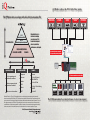
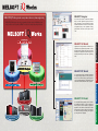
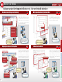
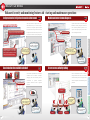
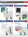
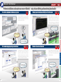
Mitsubishi iQ Platform-compatible
FA Integrated Engineering Software
MELSOFT iQ Works
NEW
DVD version also available
Mitsubishi FA Integrated Concept
iQ Works reduces the TCO with 5 key points.
The iQ Platform writes a new chapter in the book of factory automation (FA).
E RP
(Enterprise Resource Planning)
Information link
MES
(Manufacturing Execution System)
Engineering Software
Controller and HMI
Engineering Software
PLC programming and
maintenance software
A higher level
programming
Quick acquisition of
information!
Individual products
are now integrated!
The entire system can be
designed with one product.
More clear and easier to use!
No longer need to
repeat the same work!
The information you want to
know can be quickly obtained!
Economical set pricing!
Mitsubishi iQ Platform-compatible
FA Integrated Engineering Software
Network
Sequence
Ethernet
Process
CC-Link IE Control,
MELSECNET/H
Motion
A brand-new
user interface!
Mitsubishi Electric is
dedicated to helping
you reduce your TCO
from the development
phase to production,
maintenance, and beyond.
Network
Controller and HMI
Designing integrated
systems becomes easier!
GOT (HMI)
iQ Platform-compatible controller and HMI
CC-Link IE Field
Motion programming and
maintenance software
CNC
Robot
CC-Link, CC-Link Safety,
SSCNET
HMI screen creation software
GOT
CC-Link/LT
Mitsubishi Electric's "e-F@ctory" FA integrated solution is an evolutionary step in manufacturing which can provide
dramatic cost-saving results. Reduce your TCO and stay one step ahead of the competition by using advanced technologies to optimize the entire factory, including the development, production and maintenance phases of operation. The key to
this integrated concept is the "iQ Platform." By combining the power of best-in-class components on the same platform,
unparalleled levels of performance are possible. In addition, a vast array of communications options ensures connectivity
between every element of the production process, from the smallest sensor to the most complicated IT system.
The iQ Platform is a Mitsubishi FA integration concept.
Multiple CPU
high-speed
main base module
Power
supply
module
PLC CPU
Motion
controller
CPU
Network
controller
module
All
MELSEC Q Series
modules
The iQ Platform maximizes the potential performance of each system component.
5 key points for TCO reduction with iQ Works
Individual products
are now integrated!
The entire system can be
designed with one product.
More clear and easier to use!
No longer need to
repeat the same work!
The information you want to
know can be quickly obtained!
Economical set pricing!
Enhanced Function Linkage and Data Sharing
MELSOFT Navigator
Designing systems combining Mitsubishi
programmable controllers, motion controllers
and GOTs became easier.
System Configuration Diagram
The visual display of network configuration
and unit configuration enables an easy
recognition of components.
MELSOFT GX Works2
MELSOFT MT Works2
Details/Setting Information Display
The system configuration, I/O assignment
settings and network settings can be
confirmed in one display.
Integration of Software
MELSOFT GX Works2, MELSOFT MT
Works2 and MELSOFT GT Works3 were
integrated.
System Management
Software
MELSOFT Navigator
For details, refer to P. 8
MELSOFT GT Works3
Shared labels
Reduce labor and avoid setting mistakes by
sharing label definitions.
Sharing User Interface
PLC Engineering
Software
The tab display and docking windows
make the screen use more convenient.
MELSOFT GX Works2
For details, refer to P. 8
Function Blocks and Layers
The status of the whole system can be
recognized easily, by managing programs
by layers.
For details, refer to P. 7
System Monitor
The source of the error and its contents
can be diagnosed quickly, during an error
occurrence.
For details, refer to P. 7
Integration of Components
Software for programming, for simulator
and for configurator was integrated.
INDEX
Item
Page
Manage projects in groups
7
Confirm unit configuration and setting easily
7
Easy-to-design system configuration
8
Shared labels
8
Reflect the system configuration to the parameter setting
9
Display related programs directly
9
Motion system templates are available
10
Batch read all project data
10
Use the screen display area effectively
11
Display instruction or label options
11
Write equations directly into the ladder
12
Ladder to function blocks
12
Configure and monitor intelligent function modules without manuals 13
For details, refer to P. 11
Sharing User Interface
Motion Controller
Engineering Software
Common user interface to MELSOFT GX
Works2 is adopted.
MELSOFT MT Works2
For details, refer to P. 15
Sharing User Interface
HMI Screen
Creation Software
MELSOFT GT Works3
The software’s functionality has been built
around the concepts of ease use, simplification and elegance.
For details, refer to P. 19
For details, refer to P. 12
Edit programs by flowcharts
It is possible to write machine operations
in flow chart form while monitoring and
debugging.
For details, refer to P. 15
Library Function Enhanced
Programs can be created easily, by using
a large range of sub-programs.
For details, refer to P. 20
For details, refer to P. 14
Help Function Enhanced
Settings can be configured without having to
reference a manual, since explanations of
parameters and others are displayed on the screen.
For details, refer to P. 15
Improved visibility of dialog boxes
Display contents, such as ON/Off
conditions of switches and lamps, can be
confirmed in a list.
For details, refer to P. 20
For details, refer to P. 13
Integration of Components
The motion controller debugging can be
performed on a personal computer.
For details, refer to P. 17
Integration of Simulators
HMI simulators are combined,
operations can be confirmed easily.
Simulation function available as default
13
Module and network status diagnosis
14
Secure access authority setting
14
Confirm unit configuration and setting easily
15
Edit programs by flowcharts
15
Easily configure a complex synchronized system
16
Setting information display for positioning control
16
Test drive equipment without a program
17
Perform debugging using a simulation
17
Display operation data with digital oscilloscope
18
Monitor Function Enhanced
18
Find what you need fast with work tree categories 19
and
For details, refer to P. 21
Intelligible icons and toolbar
19
Create striking screen designs using simple operations 20
User-friendly dialog box display
20
One-click simulation
21
Easy data transfer by OS automatic selection
21
Customizable default settings
22
Selecting favorite parts from the toolbar
22
MELSOFT Navigator
Quick acquisition of
information!
MELSOFT GX Works2
A higher level
programming
MELSOFT MT Works2
A brand-new
user interface!
MELSOFT GT Works3
Designing integrated
systems becomes easier!
MELSOFT iQ Works represents a major innovation in systems engineering
MELSOFT iQ Works integrates the various programming and design software for Mitsubishi programmable controllers, motion controllers, and HMIs. The result is one seamless engineering environment.
MELSOFT Navigator
is the heart of iQ Works. It enables the effortless
design of entire upper-level systems and seamlessly integrates the other MELSOFT programs
included with iQ Works. Functions such as system
configuration design, batch parameter setting,
system labels, and batch read all help to reduce
TCO.
MELSOFT MT Works2
HMI Screen Creation Software
Motion Controller Engineering Software
MELSOFT GT Works3
PLC
is a complete HMI programming, screen creation,
and maintenance software. In order to reduce the
labor required to create detailed and impressive
applications, the software's functionality has been
built around the concepts of ease of use, simplification (without sacrificing functionality), and elegance
(in design and screen graphics).
Complete engineering solution
Motion controller
is a comprehensive motion controller maintenance
and program design software. Its many useful functions, such as intuitive settings, graphical programming, and digital oscilloscope, simulator all help to
reduce the TCO associated with motion systems.
GOT
MELSOFT GX Works2
Mitsubishi iQ Platform System Management Software
MELSOFT MT Works2
represents the next generation in MELSOFT PLC
maintenance and programming software. Its functionality has been inherited from both GX and IEC
Developer, with improvements made throughout to
increase productivity and drive down engineering
costs.
MELSOFT GT Works3
MELSOFT GX Works2
MELSOFT Navigator
PLC Engineering Software
MELSOFT Navigator
Integrated system management improves efficiency and thereby shortens development and maintenance time
Manage projects in groups
Development
Development
efficiency
efficiency
enhancement
enhancement
Easy-to-design system configuration
Multiple PLC, motion controller and GOT
projects are displayed in the library tree. This
enables an easier confirmation of the entire
project, because projects can be managed in
groups of process, such as factory, line or
cell.
Workspace tree
Easy
Easy
operation
operation
Visibility
Visibility
enhancement
enhancement
The visual display of network configuration
and unit configuration enables an easy
recognition of components. On the unit
configuration diagram, the power supply
capacity and the number of I/O points can be
checked.
MELSOFT Navigator
Link to unit configuration diagram
How can I handle with
the program on this line...?
It’s too much work to create
a new system configuration,
while confirming the system
configuration designed on paper...
GOT project
Motion controller project
Drag and drop
Functions such as program edit, parameter
setting and batch reading can be executed
intuitively using the graphic interface.
In addition, the possibility of making setting
errors is minimized because the entire
system is immediately visible.
Shared labels
Define labels in a single location
Development
Development
efficiency
efficiency
enhancement
enhancement
The work is going
smoothly because I can
set the parameter easily!
ed
re shar
a
s
g
n
i
t
the set
o
t
s
e
g
Chan
Labor
Labor
reduction
reduction
Define a label shared with a PLC, a motion controller, and
an HMI with MELSOFT Navigator. Using this sheared
label, changes are automatically reflected to the motion
controller project and the GOT project when some device
assignment is changed in the PLC project. This enables a
reduction of setting time and avoids setting mistakes.
I can’t see the entire
picture of the system...
I hope they are connected…
Parameter display
7
Visibility
Visibility
enhancement
enhancement
It's easy to understand
because I can set multiple
system configurations
comparing them visually!
Once I define a system label,
any change is also applied to
the other projects!
I have to set again
the same configuration
to other projects...
MELSOFT MT Works2
Confirm module configuration and setting easily
Module list
Power supply capacity and number of I/O points check
It is easy to understand
the relation between each project,
so I can easily control them!
MELSOFT GT Works3
rojects
p
e
l
p
i
t
l
mu
ment of
e
g
a
n
a
ed m
Integrat
MELSOFT GX Works2
PLC project
8
MELSOFT Navigator
Integrated system management improves efficiency and thereby shortens development and maintenance time
Motion system templates are available
Motion controller project
PLC project
s at once
t
c
e
j
o
r
p
ll
plied to a
p
a
y
l
l
a
c
i
Automat
The batch parameter
setting function makes
the work easier!
Display related programs directly
It’s too much work to set
the parameters for every
single project...
Development
Development
efficiency
efficiency
enhancement
enhancement
Labor
Labor
reduction
reduction
ailable
v
a
s
i
mplate
e
t
d
e
r
nfigu
Pre-co
Using a template, I can set
advanced motion controls
without trouble!
Batch read all project data
It’s hard to set the PLC CPU
and the motion CPU one by one...
Labor
Labor
reduction
reduction
Use the batch read function to download the
data of all PLC, motion controller, and GOT
with one operation. Consequently, It is not
necessary to start software for each device to
download these data.
From a specific command in the PLC
program, the motion programs related to the
command can be directly displayed. This
eliminates the need to open each project to
search for referenced programs.
Start
MELSOFT Navigator
Make use of templates to get started with multiCPU systems including motion controllers. The
hours for programming can be shortened,
because templates are pre-configured with
parameters and labels.
Set parameter settings for networks, I/O assignments,
and others, based on the information of the system
configuration diagram of MELSOFT Navigator, with
one operation. In addition, in the multi-CPU, once
parameters are set to a CPU module, the settings can
be reflected to other CPU modules easily.
GOT project
Labor
Labor
reduction
reduction
Jump
PLC project
Displays
ram
vant prog
the rele
Motion controller project
Referring from the command,
the related program is
displayed automatically!
9
I have to open multiple projects
and figure out which program this
command goes to and edit it...
lected
e
s
l
l
a
ad
ownlo
d
y
l
l
a
atic
stem
Autom ion in the sy
at
inform
I can execute the job
at a time, thanks to
the batch read function!
Starting the software for each
project and downloading them
is a lot of work...
MELSOFT GX Works2
Labor
Labor
reduction
reduction
MELSOFT MT Works2
Development
Development
efficiency
efficiency
enhancement
enhancement
MELSOFT GT Works3
Reflect the system configuration to the parameter setting
10
MELSOFT GX Works2
Enhance project development efficiency via the user-friendly interface
Write equations directly into the ladder
Minimize multiple displayed windows in the
"Docking window" to tabs when they are not
being edited. Likewise in the "Work window",
multiple projects can be also changed to
tabs. This enables to program efficiently,
using the work area effectively.
Labor
Labor
reduction
reduction
Write descriptions of numerical processes
and operational treatments directly into the
ladder. This keeps ladders simple, and
improves the readability of programs.
MELSOFT Navigator
Write in ST
Minimized mode
switches docking
windows to tabs
Working always with many screens,
the workspace is insufficient and
it is difficult to navigate...
The screen is easy to see
because windows not
editing can be minimized!
Display instruction or label options
Instruction options
Instruction
options are
automatically
displayed
Instruction details
Development
Development
efficiency
efficiency
enhancement
enhancement
Prevention of coding mistakes saves time with
the ability to find an instruction or label even if
the entire name is not known. Information
about the selected item is automatically
displayed insuring the correct choice is made.
Instructions include detailed usage information.
It would be easy to do this using ST,
but I need to use ladder...
It’s easy because I can write
operational expressions directly,
for parts hard to handle as ladders!
Ladder function blocks
Development
Development
efficiency
efficiency
enhancement
enhancement
Ladder to function blocks
Labor
Labor
reduction
reduction
Create your own function blocks for easy
re-use. They can be utilized easily by dragging and dropping function blocks from the
function block selection window into the
sequence programs. This improves the
development efficiency.
Instruction usage information
ns
Label optio
Just pasting function
blocks, the same ladder
can be programmed!
It becomes much easier
because the next option
is displayed!
Label options are
automatically displayed
11
I need to stop and reference
other information to make
sure this is correct...
I am writing this same
sequence of ladder instructions
over and over again.
There must be a faster way...
MELSOFT GX Works2
Click a tab to switch the work screen
Development
Development
efficiency
efficiency
enhancement
enhancement
MELSOFT MT Works2
Visibility
Visibility
enhancement
enhancement
MELSOFT GT Works3
Use the screen display area effectively
12
MELSOFT GX Works2
Enhanced security and monitoring features aid start-up and maintenance operations
When setting parameters for intelligent function modules,
detailed descriptions are given on the screen, making it
possible to set up and change the configuration of intelligent
function modules without having to reference a manual. Use
the intelligent function module batch memory monitor to create
a custom list of items to observe and quickly identify problems.
Network diagnostics
Visibility
Visibility
enhancement
enhancement
System monitor shows the status with simple
illustrations. Quickly diagnose network and
PLC hardware problems anywhere in the
system. This helps to specify error locations
and to investigate its causes.
MELSOFT Navigator
CPU diagnostics
Something is not right with
the module, but I don't know
what is going on inside...
The intelligent function module batch
memory monitor lets you view digital
values, signal, and status information
directly from the software interface.
I can grasp the error locations
and their descriptions easily,
with one look at the system monitor!
Each item shows detailed
information, so I can set
the parameter with easily!
There’s not enough
information on error
locations/descriptions...
Simulation function available as default
Start the simulator
All
All in
in one
one
Secure access authority setting
Full simulation capabilities are immediately
available with GX Works2. Accomplish
debugging tasks more efficiently with the
convenience
to
perform
simulation
anywhere, without the need for physical
hardware.
Development
Development
efficiency
efficiency
enhancement
enhancement
Prevent unauthorized accesses to data by
setting access levels for each user. Create a
multi-level security scheme to support collaborative development while maintaining data
protection.
Program C
Only authorized users
can edit the data.
This is great!
I only need a personal
computer to test this program!
It is very convenient!
Read only
I need to test this program,
but I don't have access to
the PLC...
13
User A
Read only
User B
Allowed to edit
User C
Someone has changed data
without permission.
MELSOFT GX Works2
Description of the analog output parameter
Module and network status diagnosis
MELSOFT MT Works2
Example: Analog output module
Visibility
Visibility
enhancement
enhancement
MELSOFT GT Works3
Configure and monitor intelligent function modules without manuals
14
MELSOFT MT Works2
Create advanced motion control systems with ease
Easily configure a complex synchronized system
The system setting screen relies largely on
illustrations. Easy to set up servo amplifiers and
modules for system configuration. The software
provides details about the parameters so they
can be configured without needing to refer to a
manual.
Development
Development
efficiency
efficiency
enhancement
enhancement
Easy
Easy
operation
operation
Visibility
Visibility
enhancement
enhancement
Drag and drop motor- and cam-shaped icons
(mechanical modules) to place them in the same
configuration as the control target system. Only
parameter setting creates complex synchronous
control system. Modify CAM patterns visually to
further aid the design process.
MELSOFT Navigator
I want to execute synchronous
control on multiple axes, but I
don't know how...
Motion systems need
a lot of settings…
Descriptions to operate
are on the screen. I do not
need manuals anymore!
Edit programs by flowcharts
I can execute complex
synchronous control easily
by using simple icons!
Development
Development
efficiency
efficiency
enhancement
enhancement
Visibility
Visibility
enhancement
enhancement
Setting information display for positioning control
It is possible to write machine operations for
the control target in flow chart form while
monitoring and debugging. Use the
instruction wizard to quickly and easily write
programs only by responding the questions
appearing on the screen.
I forgot what page in the manual
this instruction was on…
Indication helps are
on the screen. I do not need
to refer manuals anymore!
I want to quickly make a
motion control program
that's easy to understand...
15
Visibility
Visibility
enhancement
enhancement
Configure advanced motion control programs without
the need for a manual. Simply pick the desired servo
commands from the instruction list and the help
(instruction help) is right there. Follow the help and set
items like axis number, positioning address, and
positioning speed to complete the configuration.
Instruction help
Flowcharts help me to
understand the entire
configuration with ease!
Easy
Easy
operation
operation
MELSOFT GX Works2
Visibility
Visibility
enhancement
enhancement
MELSOFT MT Works2
Easy
Easy
operation
operation
MELSOFT GT Works3
Confirm unit configuration and setting easily
16
MELSOFT MT Works2
Perform installations and maintenance more efficiently using enhanced debug and monitoring functionality
Display operation data with Digital Oscilloscope
Visibility
Visibility
enhancement
enhancement
Digital oscilloscope plots feedback data
synchronized with motion controller data on the
same graph to quickly reveal any problems.
Using this feature makes start-up and commissioning quick and easy. Also MT Works2 makes
it easy to save the collected data in CSV format.
I can check basic instructions
running in test mode without
a program!
MELSOFT Navigator
It seems to be working, but
I want to make sure the machine
is working as it should…
It is easy to check
the data in time axis!
The machine is not completed yet,
but I want to test motor operation...
Perform debugging using a simulation
Development
Development
efficiency
efficiency
enhancement
enhancement
All
All in
in one
one
Program debug mode and the digital oscilloscope
function allow for easy testing of motion SFC
programs, servo programs, and mechanical system
programs all without the need for real hardware.
Easily recognize the simulator with debug in flow chart
form and synchronized data in calculation cycle.
Monitor Function Enhanced
Development
Development
efficiency
efficiency
enhancement
enhancement
Improve installation and maintenance operation
efficiency by using one of the many monitoring
tools, monitor the motion controller's status, or
batch monitor errors.
An error has occurred, but
I have no idea what caused it...
I want to debug but we don’t
have the actual equipment yet…
We have a simulator to debug
and improve the program!
17
Visibility
Visibility
enhancement
enhancement
I can identify the error
location easily!
MELSOFT GX Works2
Run basic instructions in test mode without
programming. Test a new system with functions
like return to home position, JOG, and others
with just the click of a mouse.
Development
Development
efficiency
efficiency
enhancement
enhancement
MELSOFT MT Works2
All
All in
in one
one
MELSOFT GT Works3
Test drive equipment without a program
18
MELSOFT GT Works3
Enhanced user-friendliness makes it easier than ever to get started quickly
Create striking screen designs using simple operations
Click and
place
I can find the file
I'm looking for quickly!
It is easy to find
the library I need!
It is not easy to
find what I need...
I want to set the barcode,
but I am not sure where to start...
Intelligible icons and toolbar
Development
Development
efficiency
efficiency
enhancement
enhancement
Visibility
Visibility
enhancement
enhancement
Many icons on toolbar are easily identified.
Hovering over icons with the mouse now
provides detailed tool-tips. The user tool bar
now remembers the last function used to
further increase screen design efficiency.
19
User-friendly dialog box display
Development
Development
efficiency
efficiency
enhancement
enhancement
Visibility
Visibility
enhancement
enhancement
Set-up and operation of the system has been simplified
by including easy-to-identify tabs. Tabs which have
already been configured are noted with asterisk to show
designers that object settings have been modified.
Arrange On/Off switches and images by variable
number range and check them as you configure them.
I can understand the display
by just looking at! It is easy
to make a setting!
I can understand what
these icons do by just
pointing the items!
Displays an explanation of
the function when the mouse
is placed over the icon
MELSOFT Navigator
Double-click to
create new data
Users just need to choose object data they need, and drag
and drop the data to where they want to place. The library tree
has been reorganized and sorted to help users find the right
element more quickly. For example, it is now possible to jump
directly to items based on "appearance" or "function." A feature
to select items from a recent history list is also included.
I cannot tell what these icons
do by just looking at them...
I'm not sure what and
where to set in this switch...
MELSOFT GX Works2
The work tree automatically organizes every piece of your
project so it's easy to find later. The files are split among
three logical categories: "Project", "System" and "Screen".
Then, you know where to look intuitively. Additionally you
can now create new screens or comments directly from
the work tree by double clicking "New."
Easy
Easy
operation
operation
MELSOFT MT Works2
Development
Development
efficiency
efficiency
enhancement
enhancement
MELSOFT GT Works3
Find what you need fast with work tree categories
20
MELSOFT GT Works3
Customizable default settings
Labor
Labor
reduction
reduction
Save time by choosing your own defaults for
shapes and objects. Registering the most
frequently used settings as defaults saves
you the trouble of making the same changes
repeatedly to each of those objects.
Number
display icon
MELSOFT Navigator
Verify the correct operation of GOT projects
on a PC, without the need for GOT or PLC
hardware. Check that the system alarms
operate, screen transitions are correct, and
monitor devices all using the simulator.
(Excluding GT10)
Development
Development
efficiency
efficiency
enhancement
enhancement
Click and
place
Click the mouse to
simulate touch operation
Before customizing
I can check the operation easily
by just clicking the simulator!
I can register the style I often use
as a default setting, and I do not need
to make a same setting anymore!
I want to verify the data
I created without the actual
equipment…
Changing each of these
objects to the style I want
takes so much time...
* GX Works2 or GX Simulator is required
Easy data transfer by OS automatic selection
Easy
Easy
operation
operation
Selecting favorite parts from the toolbar
Because different GOT operating systems are
required based on the screen data present, the
screen design software will automatically
choose and upload the correct OS when
transferring projects to the GOT. Therefore
users do not need to choose the OS manually.
Data transfer
Data transfer
Data transfer
21
The description
of "Favorite library"
will appear.
Labor
Labor
reduction
reduction
Create a collection of favorite parts to avoid
configuring from default every time. Registering the favorite parts to “Favorite library”
and the parts appear on "Favorite toolbar”.
Objects in the "Favorites tool bar" can be
picked and placed quickly.
Click and
place
The screen design software
automatically choose the OS I need.
I do not have to choose it!
Select data and OS automatically
Favorites
toolbar
Development
Development
efficiency
efficiency
enhancement
enhancement
If I add often-used objects
o "Favorites tool bar",
I can find them easily!
I do not know which
OS to select…
I often need the same style parts...
MELSOFT GX Works2
All
All in
in one
one
MELSOFT MT Works2
One-click simulation
labor necessary for screen design
MELSOFT GT Works3
GT Works3 is easier to use, reducing the
22
The iQ Platform excels in bringing superior
performance to multiple CPU systems. The
key is the redesigned back-plane which
allows for vastly increased CPU-to-CPU
transfer speeds while maintaining full
backward compatibility with Q Series hardware. The PLC CPUs have an increased
memory sharing capacity and operation
speeds in the nanosecond range which
further helps to reduce takt time of production machines and manufacturing devices.
PLC Engineering Software
PLC
PLC
Mitsubishi iQ Platform System Management Software
HMI Screen Creation Software
Motion Controller Engineering Software
The motion controller CPUs realize high
accuracy, synchronous, speed/position control
by executing communications with servo
amplifiers in as little as a 0.44ms. Customize
your motion solution by taking advantage of
motion control functions such as multi-axis
interpolation, speed control, electronic cam,
tracking control, and more. In addition, the
MELSOFT MT Works2 engineering environment has been optimized to substantially
reduce program development and debugging
times.
Motion controller
Motion controller
PLC
Industrial automation, evolved.
Motion controller
GOT
Factory Automation has made an evolutionary leap thanks to
Mitsubishi Electric's combination of several leading-edge technologies.
With a high-speed, high-capacity PLC, and a high-speed, high-accuracy motion,
these iQ Platform-compatible controllers unleash unprecedented performance using advanced
multiple CPU high-speed communication.
With the introduction of system labels, the
labor required for system development has
been greatly reduced. There is no longer a
need to memorize devices as they can be
easily searched. And now, configuring
connected devices and drivers has never
been easier. Using the batch parameter
setting function in MELSOFT Navigator, it is
easy to create parameters for all connected
devices, drivers, and interfaces.
GOT
GOT
compatible PLC
The results of a quest for the highest performance and operating speeds approaching the lower boundary of the nanosecond scale
Increase the production rate with ultrahigh-speed processing
Major improvements in operational performance
performance, (LD) of 9.5ns, in response to building demands
for increased system production rates.
● With the increased speed of basic operation processing
9.5ns
QnUD (E) HCPU
Universal model
34ns
High-performance model QnHCPU
Basic operation processing speed (LD) [ns] 0
comes scan time reductions, and improvements in processing accuracy. High-speed control (previously only supported
by micro-computer boards) using these PLC CPUs has
become a viable solution.
PLC
Approx. 3.5 times faster!
● New CPU models offer ultrahigh-speed basic operation
5
10
15
20
25
30
35
40
Approx. 5.8 times faster!
60 instructions/
QnUD (E) HCPU
Universal model
10.3 instructions/
High-performance model QnHCPU
PC MIX value [instruction/
]*
0
10
20
30
40
50
60
70
80
* The PC MIX value is the average number of instructions such as the basic
and data processing instructions executed in 1 .
The larger the value, the higher the processing speed.
High-speed, high-accuracy real data processing
● In order to speed up production data calculations, the floating point
Approx. 13.7 times faster!
● Calculation errors of complex equations can be reduced
using the newly added double accuracy operation.
High-performance model
0.057
0.78
High-performance model QnHCPU
Floating point addition (single accuracy)
instruction processing speed [ ]
0
0.1
0.2
0.3
0.4
Universal model
QnUD (E) HCPU
QnUD (E) HCPU : Q04/ 06/ 10/ 13/ 20/ 26UDHCPU,
Q04/ 06/ 10/ 13/ 20/ 26/ 50/ 100UDEHCPU
QnHCPU
: Q02/ 06/ 12/ 25HCPU
Universal model
QnUD (E) HCPU
Universal model
0.5
0.6
0.8
0.9
High-performance model
QnHCPU
0.057
4.3 *1
Addition Single accuracy [ ]
( E+) Double accuracy [ ]
0.7
0.78
87 *2
*1 Minimum value. *2 Indicates internal double accuracy operation processing speed.
High-speed and high-accuracy machine control made possible with multiple CPUs
Increased program capacity
Multiple CPU high-speed communication
tion is capable of simultaneously processing multiple CPU highspeed communication (14k words/ 0.88ms), executing a sequence,
process or motion program, and performing high-speed machine
control. In motion applications, the motion control operations are
synchronized using multiple CPU high-speed communications.
Multiple CPU high-speed communication
PLC CPU
Program example
In-position Servo program start
signal
dedicated instruction
D(P).SVST
Measurement
details
Motor speed
Time
In-position signal
Multiple CPU high-speed
main base unit
Motion
Universal model
PLC control processor
Multiple CPU
high-speed
communication memory
Multiple CPU
high-speed bus
Device memory
Multiple CPU
high-speed
communication memory
Motion control
processor
SSCNETIII
In a multiple CPU system (a PLC and a motion controller), with
the in-position signal from the servo amplifier of the first axis
(used by motion controller) as the trigger, the PLC sends a start
command to the servo amplifier of the second axis. The time it
takes for the servo amplifier of the second axis to output the
speed command is called the in-position response time, and
this time is a good indicator of CPU-to-CPU data transfer speed.
Q Series PLC system bus
Optimization of in-position signal response time
PLC I/O module
(Digital I/O)
Multiple CPU high-speed
communication compatible
model
PLC intelligent function
module
(A/D, D/A, etc.)
Motion controller
modules
Servo
amplifier
Q04U
Q06U
Q10U
Q20U
Q26U
Q50U
Q100U
Q13U
25
Q03U :Q03UDECPU, Q03UDCPU
QnUD(E)HCPU+Q173DCPU
High-performance model
QnHCPU+Q173HCPU
QnUD(E)HCPU+Q173DCPU
High-performance model
QnHCPU+Q173HCPU
Capacity [k words] 0
Standard ROM capacity
(flash ROM)
Q01U
Q02U
15k
20k
10k
No. of programs
32
Approx. 3.5 times faster!
14k words
4k words
4
8
12
16
Q04UDEH Q06UDEH Q10UDEH Q13UDEH Q20UDEH Q26UDEH
Q03UD
Q04UDH
Q06UDH
30k
40k
60k
Q10UDH
Q13UDH
Q20UDH
Q26UDH
100k
130k
200k
260k
64
256KB
124
512KB
Q50UDEH Q100UDEH
500k
1000k
124
1MB
2MB
4MB
4MB
● The capacity of standard RAM, which can be used as file register, has been increased to store larger amounts of production and quality data. Additionally,
large-capacity SRAM cards are now supported. An 8MB SRAM card can be used as file register for 4086k words (max.) to handle large volumes of data.
Standard RAM capacity (file register capacity)
Q00U
Q01U
Q02U
128KB
(64k words)
-
Long
Q03UDE
Large-capacity memory for large-volume data
Q00UJ
Multiple CPU shared memory capacity
Universal model
Program capacity
(Step)
Q00U
Approx. 2 times faster!
In-position response time Short
Motor
The indicated CPU icons of compatible model include the Ethernet port type and RS-232 port type. (Q03U or later)
Example)
Universal model
(Proximity dog signal, manual pulse input)
Q03U
Program
memory
<In-position response time>
Q00UJ
CPU
In-position response time
Motion
PL C
● Programs are divided into 124 (max.) sub-programs according to categories such as product and process. This facilitates structuring programs into
individual routines. Such structured programs can be highly specialized to enhance visibility for detailed program management. In addition, standard ROM
(4MB max. capacity) enables the storage of device labels and comments for function block and sequence programs to be stored in the PLC CPU.
[K0: Real]
1 INC-1
Axis 1, 200PLS
Speed 10000PLS/sec
PLC
Device memory
Efficient management by structuring programs into individual routines
Motion CPU
GOT
● Each programmable controller CPU in the multiple CPU configura-
Motion controller
addition instruction's processing time has been reduced to 0.057 .
Q03UDE
Q04UDEH
Q06UDEH
Q10UDEH
Q13UDEH
Q20UDEH
Q26UDEH
Q03UD
Q04UDH
Q06UDH
Q10UDH
Q13UDH
Q20UDH
Q26UDH
192KB
(96k words)
768KB
256KB
(128k words) (384k words)
1024KB
(512k words)
1280KB
(640k words)
Q50UDEH
Q100UDEH
1536KB
1792KB
(768k words) (896k words)
Memory card (SRAM)
Model
Q2MEM-1MBS
Q2MEM-2MBS
Q3MEM-4MBS
Capacity
1MB
2MB
4MB
8MB
File register capacity *
505k words
1017k words
2039k words
4086k words
Q3MEM-8MBS
* Maximum capacity when the memory card is used as file register.
Memory card cannot be used for Q00UJ, Q00U, and Q01UCPU.
26
compatible Motion Controller
New algorithms result in high-speed and high-accuracy solutions
Optimal system construction
● Up to 4 CPU modules can be freely selected in the multiple
● Up to 96 axis per system can be controlled using mul-
● An optimum decentralized control system can be constructed
● SSCNETIII based MR-J3 servo amplifiers deliver a high-
using multiple CPUs. Control is optimized by dispersing processing across the multiple CPUs with the PLC handling general machine control and the motion controller handling servo
control tasks. System expandability is accomplished with
ease due to the availability of over 100 different types of
MELSEC Q Series modules.
tiple motion CPUs (three Q173DCPU modules).
speed, high-accuracy solution.
PLC
CPU system (one PLC CPU required).
SSCNET (Servo System Controller NETwork)
Multiple CPU high-speed data transfer
Shared memory capacity
3.5 times increase!
The multiple high-speed
transmission cycle is the same
as the motion control cycle time.
Motion processing acceleration
the motion operational performance
(0.44ms/6axis) as previously possible has resulted
in increased production rates.
● Extremely
accurate synchronous control and
speed/position control realized thanks to the
increased speed of the axial control cycle.
● A motion control-specific processor (high-performance
64bitRISC) and a proprietary acceleration algorithm
ASIC improve hardware efficiency.
Basic motion performance
(With 0.44ms operation cycle time)
In case of SV13
Q173DCPU
Performance
● Equipped with various motion control functions
such as multi-axis interpolation, speed control,
electronic cam and tracking control.
Approx. 2 times faster!
● Motion-dedicated PLC instructions have become easier
Issue multiple instructions at the same time
1. A motor real-time value can be compared against
a specific point, and if this point is overrun, the PLC
can turn on an output signal. (Variation of comparison
processing does not have an influence on the scan
time of the ladder which is processed within 0.88ms.)
Example: Execution of three motion-dedicated SVST instructions at the same time
Large reduction in programming read/write time
3 axes
and writing to the motion controller (Q173DCPU/Q172DCPU use).
1/4 the Motion SFC processing time
M0
Ladder program
DP.SVST
H3E1
“J1”
K0
DP.SVST
H3E1
“J1”
K0
DP.SVST
H3E1
“J1”
K0
RST
M0
Example: Indirect data setting of speed and position plus execution of
the motion-dedicated SVST instructions all at the same time
M0
Ladder program
Servo program read time
Process time for D800L = D802L + D804L
Q173DCPU
Processing
time
Indirectly set data and execute instructions at the same time
Motion CPU communication time
Motion SFC processing time
Q173DCPU
to use.
[Application Example]
● Substantial shortening of communication time when reading
Q173HCPU
27
● Using the new PLC interrupt function synchronized with the motion operation cycle
6 axes
Q173HCPU
● Reduce variations in response time by using
motion SFC programming.
Motion-dedicated PLC instruction
2. Multiple motion controllers can be started simultaneously.
● Using the MELSEC Q Series universal model CPU,
sequence processing is also accelerated. (Using the
Q06UDHCPU, the PLC basic instruction time is 9.5ns.)
4k words
PLC program interrupt for multiple CPU synchronization
(0.88ms), it is possible to achieve real-time processing of ladder programs.
Approximately double the basic motion performance
Q06HCPU+Q173HCPU
Q173HCPU
Reduced to approx. 1/4!
Processing Reduced to approx. 1/3!
time
Servo program
DMOV
K10000
U3E0
G12046
DP.SVST
K500
U3E0
G12048
DP.SVST
H3E1
“J1”
GOT
● Twice
Increased
controllability
14k words
Motion controller
Q06UDHCPU+Q173DCPU
Capacity (Up to14k words)
K0
[K0: Real]
1 INC-1
Axis 1.U3E0 G12046 PLS
Speed U3E0 G12048 PLS/s
2.34
11.75
28
compatible HMI
Improve production site efficiency with the integration of HMI and iQ Platform-compatible products
● Various data such as the PLC CPU program, motion controller program
and parameters can be backed up to the CF card in the GOT.
<Supported data> Programs, parameters, device comments, device
default data, file registers, etc.
<Supported models> MELSEC Q Series (excluding Q12PRH/Q25PRHCPU),
MELSEC L Series, Q Series motion controllers (SV13/SV22
only), CNC C70, Robot controller
● Users can perform batch operations to restore the data to
the PLC CPU or motion controller.
<Supported connection type> Bus connection, CPU direct connection, computer
link connection, Ethernet connection (host only)
The backup data conversion tool is shipped with GT Works2/GT Designer2
Make a data back up in case of PLC or CPU failure or a dead battery, and
quickly replace the faulty device and restore the system using the backup.
PLC
Backup/Restore function
When a problem occurs, or when the PLC CPU program is updated, the
sequence program data can be transferred, analyzed, and corrected without
requiring an experienced engineer, increasing time and cost efficiency.
If data is backed up
Worksite
Office
CF card,
etc.
MODE
RUN
ERR
USER
BAT
BOOT
Q61P-A1
USB
PULL
Sequence
program,
etc.
Replace CPU
POWER
Q25HCPU
MODE
RUN
ERR
USER
BAT
BOOT
PULL
USB
PULL
QX10
QX41
QX41
QJ71BR11
RUN
T.PASS
SD
ERR
MNG
D.LINK
RD
ERR
QJ71BR11
RUN
T.PASS
SD
ERR
CF card,
etc.
Sequence
program, etc.
Restore
Data transfer
1. Backup
2. Analysis and
correction
MNG
D.LINK
RD
ERR
Q61P-A1
0
1
2
3
4
5
6
7
8
9
A
B
C
D
E
F
POWER
Q25HCPU
QX10
MODE
RUN
ERR
USER
BAT
BOOT
PULL
CPU direct
connection
USB
PULL
QX41
QX41
QJ71BR11
RUN
T.PASS
SD
ERR
MNG
D.LINK
RD
ERR
QJ71BR11
RUN
T.PASS
SD
ERR
MNG
D.LINK
RD
ERR
CF card,
etc.
0
1
2
3
4
5
6
7
8
9
A
B
C
D
E
F
3. Restore
Sequence programs saved on the CF card or other
memory devices can be edited in GX Developer after
having been converted by the backup data conversion tool
PLC CPU programs can be easily changed without a personal computer at the worksite or any previous GX Developer knowledge
* : When replacing the PLC CPU, the restore function may not be available depending on the system configuration and connection type.
An optional device may be necessary
Ladder monitor function
* : Compatible with XGA/SVGA/VGA model.
* : The QS Series can only monitor with the
Q/QnA ladder monitor function. You cannot
change device values.
* : FX3GCPU is not supported.
Troubleshoot with the one-touch ladder jump function (Q/QnA ladder monitor)
● By setting a program name and coil number of the PLC to a touch
switch, the desired ladder circuit block can be displayed directly.
Ladder edit function
Mitsubishi Q Series (Q mode) and CNC C70 PLC programs can be
edited in ladder format.
Easy ladder editing with GOT at your worksite
● Select “SP Function” → “Ladder Monitor” from the
touch switch property dialog box.
● Simply by touching the part in the ladder program you want to edit, such as a contact
Display the ladder block of the
coil set to the touch switch
Edit
Hard
copy
Jump to ladder monitor
screen with a single touch
Monitor
Menu
Insert row
● In addition to the PLC connected to the GOT, other stations including
a
h
●
●
●
●
An optional device may be necessary
Example of defect search (when error indicator light [Y10] is on)
ST1 error
M10
ST2 error
M20
Y10
<Display ladder blocks including M20>
Error indicator
light: ON
Touch normally open
contact (M20) in ON state
(Coil search function)
Pusher LS error
M31
Air pressure error
M32
Oil pressure error
M33
M20
ST2 error
Error is detected
because oil pressure
error (M33) is on
Touch
Find the root cause of problems quickly, right from the machine.
Find/Replace Convert
Switch Display Online
Changed to a make contact
with M200
M422
Improve maintenance work efficiency with a wide monitoring range of useful functions
<Display ladder blocks including Y10>
Edit
Circuit input
Circuit input
multi CPUs can be monitored. Multiple programs and local devices
in every CPU can be monitored.
Save sequence program comments to the CF card in the GOT
(Q/QA ladder monitor).
Device values and timer (T)/counter (C) set values can be changed.
Execute a coil search or contact point search simply by touching the
(Q/QnA) ladder monitor screen. <Touch search>
When an alarm occurs, perform a back-tracking ladder search to find
the contact that triggered the alarm. <Defect search>
each place to edit, but it is also easy to correct multiple places in
a batch.
Find/Replace Convert Switch Display Online
Touching the part you want to edit
opens the circuit input window
Set PLC station No., CPU No., destination
device, ladder search mode (coil
search/factor search), and program file
name. (Example) [Program name: AUTO-L1,
Network No.: 2, Station No.: 3, M100]
End
Auto drive
● You can also find and replace a device. Not only it is easy to find
point or a line, you can input, change or delete circuit symbols and devices. You can
also insert or delete vertical and horizontal lines, and insert or delete rows and columns.
PC
read
* : Supports the SVGA/SVGA/VGA model except 5.7 model.
* : QnPHCPU/QnPRHCPU are not supported.
b
i
Delete row
c
j
Circuit symbol: a break contact to a make contact
Device: Change from M422 to M200
e
d
k
< >
Insert row
a
h
b
i
]
g
1
n
5
3
2
6
4
< >
[ ]
7 ENT
Delete row
c
j
d
k
e
l
M200
Delete column
Insert column
f
m
l
[
GOT
This function monitors Mitsubishi Q/QS/QnA/A/FX Series PLC sequence
programs using a circuit diagram (ladder format).
Motion controller
Q25HCPU
Delete column
Insert column
f
m
g
1
n
5
2
6
3
7
4
ENT
Writing to the PLC
Monitor, search and test the ladder program
● After you edit the program, you can “stop” it remotely from
● You can display the current value, search and execute device test on the ladder program.
GOT to write it, and then “run” it remotely.
Testing the edited program can be executed immediately.
Wide range of access
An optional device may be necessary
● In addition to the PLC connected to the GOT, you can access other stations (PLCs) in
the network including multiple CPUs. You can edit multiple programs in every CPU.
29
30
Software model list
MELSOFT Navigator compatible module list (Version 1.10Z)
Contents
Model name
Category
Category
Model name
Model name
Mitsubishi iQ Platform-compatible FA integrated engineering software suite with additional integrated functions CD-ROM version
Mitsubishi iQ Platform-compatible system management software [MELSOFT Navigator] (English version)
+Mitsubishi iQ Platform-compatible PLC engineering software [MELSOFT GX Works2] (English version)
+Mitsubishi iQ Platform-compatible motion controller engineering software [MELSOFT MT Works2] (English version)
+Mitsubishi iQ Platform-compatible HMI screen design software [MELSOFT GT Works3] (English version)
Q00UJCPU
QX10
Q00UCPU
QX10-TS
Q01UCPU
QX28
Q02UCPU
QX40
Mitsubishi iQ Platform-compatible FA integrated engineering software suite with additional integrated functions DVD-ROM version
Mitsubishi iQ Platform-compatible system management software [MELSOFT Navigator] (English version)
+Mitsubishi iQ Platform-compatible PLC engineering software [MELSOFT GX Works2] (English version)
+Mitsubishi iQ Platform-compatible motion controller engineering software [MELSOFT MT Works2] (English version)
+Mitsubishi iQ Platform-compatible HMI screen design software [MELSOFT GT Works3] (English version)
Q03UDCPU
QX40-TS
Q03UDECPU
QX40-S1
Q04UDHCPU
QX40H
Q04UDEHCPU
QX41
MELSOFT GX Works2 SW1DNC-GXW2-E
MELSEC PLC programming SW programming function + intelligent unit function + simulator function (English version)
Q06UDHCPU
QX41-S1
MELSOFT MT Works2 SW1DNC-MTW2-E
Mitsubishi iQ Platform-compatible motion controller engineering software (English version)
Q06UDEHCPU
QX41-S2
MELSOFT GT Works3 SW1DNC-GTWK3-E
Screen design software for GOT + simple data conversion function + GT SoftGOT1000 function + simulator function (English version)
Q10UDHCPU
QX42
MELSOFT iQ Works
iQ Platform-compatible
FA integrated
engineering software MELSOFT iQ Works
SW1DNC-IQWK-E
SW1DND-IQWK-E
Universal model CPU
* : Please contact your nearst sales office or distributor for details of multiple license versions.
Q13UDHCPU
MELSOFT iQ Works system requirements
Contents
Windows2000 Professional, Service Pack 4
WindowsXP Professional, Service Pack 2,3
WindowsXP HomeEdition, Service Pack 2,3
Windows Vista Home Basic, Service Pack 1,2
Windows Vista Home Premium, Service Pack 1,2
Windows Vista Ultimate, Service Pack 1,2
Windows Vista Business, Service Pack 1,2
Windows Vista Enterprise, Service Pack 1,2
OS(Only 32 bit OS)
Basic model CPU
Desktop: Celeron 2.8 GHz or faster
Laptop: PentiumM 1.7 GHz or faster
CPU
Memory
1GB or more
Display
XGA (1024 × 768) or higher
Available space
For installation: 3 GB of hard disk space
For operation: 512MB virtual memory available
High-performance model CPU
Main base unit
MELSOFT iQ Works compatible version
Contents
MELSOFT GX Works2
Version 1.30G or later
MELSOFT MT Works2
Version 1.09K or later
MELSOFT GT Works3
Version 1.14Q or later
Q03UDCPU
Q04UDHCPU
Q06UDHCPU
Q13UDHCPU
Q26UDHCPU
Q03UDECPU
PLC
Q04UDEHCPU
iQ Platform-compatible
controller
Q06UDEHCPU
Q13UDEHCPU
Q26UDEHCPU
Q50UDEHCPU
Q100UDEHCPU
C language CPU
Motion
Main base unit
Q12DCCPU-V
Q172DCPU
Q173DCPU
Q38DB
Q312DB
Contents
No. of I/O points: 4096 points, no. of I/O device points: 8192 points, program capacity: 30k steps
basic operation processing speed (LD instruction): 20ns, program memory capacity: 120kb, multiple CPU high-speed communication
peripheral connection ports: USB and RS232, with memory card I/F
No. of I/O points: 4096 points, no. of I/O device points: 8192 points, program capacity: 40k steps
basic operation processing speed (LD instruction): 9.5ns, program memory capacity: 160kb, multiple CPU high-speed communication
peripheral connection ports: USB and RS232, with memory card I/F
No. of I/O points: 4096 points, no. of I/O device points: 8192 points, program capacity: 60k steps
basic operation processing speed (LD instruction): 9.5ns, program memory capacity: 240kb, multiple CPU high-speed communication
peripheral connection ports: USB and RS232, with memory card I/F
No. of I/O points: 4096 points, no. of I/O device points: 8192 points, program capacity: 130k steps
basic operation processing speed (LD instruction): 9.5ns, program memory capacity: 520kb, multiple CPU high-speed communication
peripheral connection ports: USB and RS232, with memory card I/F
No. of I/O points: 4096 points, no. of I/O device points: 8192 points, program capacity: 260k steps
basic operation processing speed (LD instruction): 9.5ns, program memory capacity: 1040kb, multiple CPU high-speed communication
peripheral connection ports: USB and RS232, with memory card I/F
No. of I/O points: 4096 points, no. of I/O device points: 8192 points, program capacity: 30k steps
basic operation processing speed (LD instruction): 20ns, program memory capacity: 120kb, multiple CPU high-speed communication
peripheral connection ports: USB and Ethernet, with memory card I/F
No. of I/O points: 4096 points, no. of I/O device points: 8192 points, program capacity: 40k steps
basic operation processing speed (LD instruction): 9.5ns, program memory capacity: 160kb, multiple CPU high-speed communication
peripheral connection ports: USB and Ethernet, with memory card I/F
No. of I/O points: 4096 points, no. of I/O device points: 8192 points, program capacity: 60k steps
basic operation processing speed (LD instruction): 9.5ns, program memory capacity: 240kb, multiple CPU high-speed communication
peripheral connection ports: USB and Ethernet, with memory card I/F
No. of I/O points: 4096 points, no. of I/O device points: 8192 points, program capacity: 130k steps
basic operation processing speed (LD instruction): 9.5ns, program memory capacity: 520kb, multiple CPU high-speed communication
peripheral connection ports: USB and Ethernet, with memory card I/F
No. of I/O points: 4096 points, no. of I/O device points: 8192 points, program capacity: 260k steps
basic operation processing speed (LD instruction): 9.5ns, program memory capacity: 1040kb, multiple CPU high-speed communication
peripheral connection ports: USB and Ethernet, with memory card I/F
No. of I/O points: 4096 points, no. of I/O device points: 8192 points, program capacity: 500k steps
basic operation processing speed (LD instruction): 9.5ns, program memory capacity: 2000kb, multiple CPU high-speed communication
peripheral connection ports: USB and Ethernet, with memory card I/F
No. of I/O points: 4096 points, no. of I/O device points: 8192 points, program capacity: 1000k steps
basic operation processing speed (LD instruction): 9.5ns, program memory capacity: 4000kb, multiple CPU high-speed communication
peripheral connection ports: USB and Ethernet, with memory card I/F
No. of I/O points: 4096 points, endian type: little endian, CF card: available OS: VxWorks Version 6.4
No. of control axes: 8 axes/operation cycle: 0.44ms to SSCNETIII: 1ch
No. of control axes: 32 axes/operation cycle: 0.44ms to SSCNETIII: 2ch
8 slots for installing Q Series module
12 slots for installing Q Series module
Input module
Multiple CPU high-speed main base module
Slim type main base module
Extension base module
QX70
Q20UDHCPU
QX70H
Q20UDEHCPU
QX71
Q26UDHCPU
QX72
Q26UDEHCPU
QX80
Q50UDEHCPU
QX80-TS
Q100UDEHCPU
QX80H
Q00JCPU
QX81
Q00CPU
QX81-S2
Q01CPU
QX82
Q02CPU
QX82-S1
Q02HCPU
QX90H
Q06HCPU
QY10
Q12HCPU
QY10-TS
Q25HCPU
QY18A
Q33B
QY22
Q35B
QY40P
Q38B
QY40P-TS
Q38DB
QY41P
Output module
QY50
Q32SB
QY68A
Q33SB
QY70
Q35SB
QY71
Q38RB
QY80
Q63B
QY80-TS
Q65B
QY81P
Q68B
Q612B
Q55B
QH42P
I/O module
QX48Y57
QX41Y41P
Interrupt input
QI60
Q68RB
Q68ADV
Q61P
Q62AD-DGH
Q61P-A1
Q68ADI
Q61P-A2
Power supply
QY42P
Q312DB
Q52B
Redundant power supply extension base
QX50
Q13UDEHCPU
Q312B
Redundant power supply extension base module
iQ Platform-compatible controller model list
Model name
QX42-S1
Q10UDEHCPU
Q62P
Q64AD
Analog input
Q64AD-GH
Q63P
Q64AD2DA
Q64P
Q68AD-G
Q64PN
Q66AD-DG
Life detection power supply
Q61P-D
Q61LD
Slim type power supply
Q61SP
Q68DAVN
Q63RP
Q68DAV
Q64RP
Q68DAIN
Redundant power supply
This is the MELSOFT Navigator compatible module list.
This list does not cover the compatible modules of MELSOFT GX Works2,
MELSOFT MT Works2, and MELSOFT GT Works3.
Q68DAI
Analog output
Q62DAN
Q62DA
Q62DA-FG
Q64DAN
Q64DA
Q66DA-G
Q64RD
Q64RD-G
Q68RD3-G
Temperature input
Q64TD
Q64TDV-GH
Q68TD-G-H02
Q68TD-G-H01
Q64TCRT
Temperature control
Q64TCRTBW
Q64TCTT
Q64TCTTBW
Loop control
Q62HLC
MELSOFT Navigator compatible module list (Version 1.10Z)
Category
Model name
Category
Q172CPUN
QD62
Q172CPUN-T
QD62-H01
Q173CPUN
QD62-H02
Q173CPUN-T
QD62D
QD62E
Motion controller
Q172HCPU-T
Q173HCPU
QD64D2
Q173HCPU-T
QD72P3C3
Q172DCPU
QD75P1
Q173DCPU
QD75P4
Servo external signal input module
QD70P4
Q172LX
Q172DLX
Q172EX
QD70P8
QD75D1
Q172EX-S1
Synchronous encoder input module
Q172EX-S2
QD75D2
Q172EX-S3
QD75D4
Q172DEX
QD70D4
QD70D8
Q173PX
Manual pulse input module
Q173PX-S1
QD75M1
Q173DPX
QD75MH1
GT16**-X
QD75M2
GT16**-S
QD75MH2
GT16**-V
QD75M4
GT15**-X
QD75MH4
GT15**-S
QD74MH8
GT15**-V
QD74MH16
QJ71WS96
Information module
Q172HCPU
QD63P6
QD75P2
Pulse I/O, positioning
Model name
QD60P8-G
GOT1000 series
GT155*-V
GT15**-Q
QJ71MES96
GT11**-Q
QD81DL96
GT11**-Q*BDQ (Built-in Q Bus)
QJ71E71-100
GT11**-Q*BDA (Built-in A Bus)
QJ71E71-B2
GT10**-Q
QJ71E71-B5
GT1030
QJ71C24N
GT1020
QJ71C24N-R2
QJ71C24N-R4
QJ71CMO
Ethernet
Network
CC-Link IE Control
MELSECNET/H (between PCs)
QJ71CMON
QD51
QD51-R24
QJ71LP21-25
QJ71LP21S-25
QJ71LP21G
QJ71BR11
QJ71NT11B
QJ61BT11N
QJ61CL12
Network module
QJ71FL71-T-F01
QJ71FL71-B2-F01
QJ71FL71-B5-F01
QJ71FL71-T
QJ71FL71-B2
QJ71FL71-B5
QJ71AS92
QJ71GP21-SX
QJ71GP21S-SX
ID interface module
Blank cover module
QD35ID1
QD35ID2
QG60
This is the MELSOFT Navigator compatible module list.
This list does not cover the compatible modules of MELSOFT GX Works2,
MELSOFT MT Works2, and MELSOFT GT Works3.
For Your Safety
● To use the products given in this catalog properly, always read the related manuals before starting to use them.
● The products within this catalog have been manufactured as general-purpose parts for general industries and have not been
designed or manufactured to be incorporated into any devices or systems used in purpose related to human life.
● Before using any product for special purposes such as nuclear power, electric power, aerospace, medicine or passenger movement
vehicles, consult with Mitsubishi.
● The products within this catalog have been manufactured under strict quality control. However, when installing the product
where major accidents or losses could occur if the product fails, install appropriate backup or failsafe functions in the system.
Precautions for Choosing the Products
Mitsubishi will not be held liable for damage caused
by factors found not to be the cause of Mitsubishi;
machine damage or lost profits caused by faults in
the Mitsubishi products; damage, secondary damage,
accident compensation caused by special factors
unpredictable by Mitsubishi; damages to products
other than Mitsubishi products; and to other duties.
Mitsubishi iQ Platform-compatible FA Integrated Engineering Software
MELSOFT iQ Works
Country/Region Sales office
Tel/Fax
U.S.A
Mitsubishi Electric Automation lnc.
500 Corporate Woods Parkway Vernon Hills, IL 60061, USA
Tel: +1-847-478-2100
Fax: +1-847-478-0327
Brazil
MELCO-TEC Rep. Com.e Assessoria Tecnica Ltda.
Av Paulista, 1439-Cj. 72 Cerqueira Cesar CEP 01311-200,
Sao Paulo, SP, CEP:01311-200, Brazil
Tel: +55-11-3146-2200
Fax: +55-11-3146-2217
Germany
Mitsubishi Electric Europe B.V. German Branch
Gothaer Strasse 8 D-40880 Ratingen, GERMANY
Tel: +49-2102-486-0
Fax: +49-2102-486-1120
U.K
Mitsubishi Electric Europe B.V. UK Branch
Travellers Lane, Hatfield, Hertfordshire., AL10 8XB, UK
Tel: +44-1707-276100
Fax: +44-1707-278992
Italy
Misubishi Electric Europe B.V. Italy Branch
VIALE COLLEONI 7-20041 Agrate Brianza(Milano),Italy
Tel: +39-039-60531
Fax: +39-039-6053312
Spain
Mitsubishi Electric Europe B.V. Spanish Branch
Carretera de Rubi 76-80
E-08190 Sant Cugat del Valles(Barcelona), Spain
Tel: +34-93-565-3131
Fax: +34-93-589-1579
France
Mitsubishi Electric Europe B.V. French Branch
25,Boulevard des Bouvets, F-92741 Nanterre Cedex, France
Tel: +33-1-5568-5568
Fax: +33-1-5568-5757
Czech Republic Mitsubishi Electric Europe B.V. Czech Branch
Avenir Business Park, Radlická 714/113a CZ-158 00 Praha 5
Tel: +420-251-551-470
Fax: +420-251-551-471
Poland
Mitsubishi Electric Europe B.V. Polish Branch
ul. Krakowska 50 32-083 Balice, Poland
Tel: +48-12-630-47-00
Fax: +48-12-630-47-01
Russia
Mitsubishi Electric Europe B.V. Moscow Office
52/3, Kosmodamianskaya nab., 115054, Moscow, Russia
Tel: +7-812-633-3497
Fax: +7-812-633-3499
South Africa
Circuit Breaker Industries Ltd.
Private Bag 2016,ZA-1600 Isando, South Africa
Tel: +27-11-928-2000
Fax: +27-11-392-2354
China
Mitsubishi Electric Automaiton(Shanghai) Ltd.
17/F Chong Hing Finance Center,No.288 West Nanjing Road,
Shanghai 200003 CHINA
Tel: +86-21-2322-3030
Fax: +86-21-2322-3000
Taiwan
Setsuyo Enterprise Co., Ltd.
6F., No.105 Wu-Kung 3rd.Rd, Wu-Ku Hsiang, Taipei Hsine, Taiwan
Tel: +886-2-2299-2499
Fax: +886-2-2299-2509
Korea
Mitsubishi Electric Automation Korea Co., Ltd.
1480-6, Gayang-dong, Gangseo-ku Seoul 157-200, Korea
Tel: +82-2-3660-9552
Fax: +82-2-3664-8372
Singapore
Mitsubishi Electric Asia Pte, Ltd.
307 Alexandra Road #05-01/02,
Mitsubishi Electric Bulding Singapore 159943
Tel: +65-6470-2480
Fax: +65-6476-7439
Thailand
Mitsubishi Electric Automation (Thailanad) Co., Ltd.
Bang-Chan Industrial Estate No.111 Soi Serithai 54,
T.Kannayao, A.Kannayao, Bangkok 10230 Thailand
Tel: +66-2-517-1326
Fax: +66-2-517-1328
Indonesia
P.T. Autoteknindo Sumber Makmur
Muara Karang Selatan Block A/Utara No.1 Kav.
No.11 Kawasan Industri/Pergudangan Jakarta-Utara P.O Box5045
Jakarta 11050, Indonesia
Tel: +62-21-663-0833
Fax: +62-21-663-0832
India
Messung Systems Pvt.,Ltd.
Electronic Sadan NO:III Unit No15, M.I.D.C Bhosari, Pune-411026, India
Tel: +91-20-2712-3130
Fax: +91-20-2712-8108
Australia
Mitsubishi Electric Australia Pty.Ltd.
348 Victoria Road, Rydalmere, N.S.W 2116, Australia
Tel: +61-2-9684-7777
Fax: +61-2-9684-7245
HEAD OFFICE: TOKYO BUILDING, 2-7-3, MARUNOUCHI, CHIYODA-KU, TOKYO 100-8310, JAPAN
NAGOYA WORKS: 1-14, YADA-MINAMI 5, HIGASHI-KU, NAGOYA, JAPAN
This catalog is an introduction to only part of what Mitsubishi Electric has to offer.
Mitsubishi Electric offers individualized solutions for the challenges in your factory.
L(NA)08171E-B
New publication, effective Feb. 2010
Specifications are subject to change without notice.