1
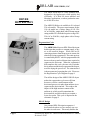
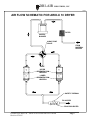
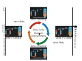
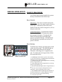
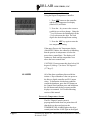
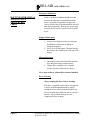
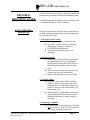
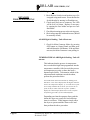
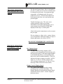
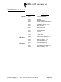
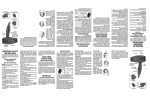
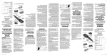
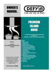
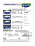
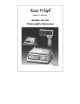
DRI-AIR INDUSTRIES, INC.
ARID-X10B FLOOR
MOUNT DRYER
OPERATING MANUAL
OPERATING MANUAL - ARID-X10B FLOOR MOUNT DRYER
Revision 3/28/02
Page 1
DRI-AIR INDUSTRIES, INC.
DRI-AIR INDUSTRIES, INC.
16 THOMPSON ROAD
P.O. BOX 1020
EAST WINDSOR, CT 06088-1020
Tel. (860) 627-5110
FAX (860) 623-4477
Internet http://www.dri-air.com
e-mail: [email protected]
Page 2
OPERATING MANUAL - ARID-X10B FLOOR MOUNT DRYER
Revision 3/28/02
DRI-AIR INDUSTRIES, INC.
CONTENTS
DRYER DESCRIPTION
Pg 4
AIR FLOW SCHEMATIC
Pg 7
DRYER CYCLE DIAGRAM
Pg 8
INSTALLATION PROCEDURES
FACILITY REQUIREMENTS
HOPPER CONNECTION
ELECTRICAL CONNECTION
POST-INSTALLATION INSPECTION
Pg 9
Pg 9
Pg 10
Pg 10
DRYER OPERATION
START-UP PROCEDURES
ALARMS
ROUTINE OPERATION
Pg 11
Pg 12
Pg 13
TROUBLESHOOTING
BASIC TROUBLESHOOTING
DETAILED TROUBLESHOOTING
ZONE VALVE TROUBLESHOOTING
CONTROLS TROUBLESHOOTING
Pg 15
Pg 16
Pg 18
Pg 18
PARTS LIST
Pg 19
ELECTRICAL SCHEMATIC 110V
Appendix
84429
Appendix
84428
Appendix
84430
ELECTRICAL SCHEMATIC 220V
DRYER CONFIGURATION
OPERATING MANUAL - ARID-X10B FLOOR MOUNT DRYER
Revision 3/28/02
Page 3
DRI-AIR INDUSTRIES, INC.
DRYER
DESCRIPTION
The ARID-X10B dryer is a fully portable dryer
designed to dry hygroscopic resins quickly and
efficiently. It is ideal for insert molders and
laboritory applications, or where production rates
are 10 lbs./hr or less.
The ARID-X10B dryer is available in 110 volt and
230 volt models. The power requirements for the
110 volt model are a voltage range of 105-130v
AC at 50/60 Hz., single phase with a 20 amp current
rating and the 230 volt model requires a range 220250v AC at 50/60 Hz., single phase with a 10 amp
current rating.
Regeneration Cycle
The ARID-X10 utilizes our HP4-X dual desiccant
bed design that provides a constant supply of dry
air to the material hopper. While one bed is
removing moisture from the process air stream, the
other bed is being regenerated. The entire process
is controlled by the PLC which is programmed with
the tower heat-up and cool down times required to
regenerate the desiccant. When the regenerated
bed completes this cycle, the zone valve switches
the air stream and the newly regenerated bed is now
used for drying the process air. The saturated bed
is then regenerated, repeating the cycle. Please see
the Regeneration Cycle Diagram on page 8.
The airflow design of the ARID-X/HP4-X dryers
makes the regeneration cycle more efficient
because we utilize a small amount of the
desiccated process air, rather than ambient air, to
regenerate the desiccant bed. This reduces the
impact of the high moisture content of the
ambient air, which would contaminate the
desiccant bed, and allows the dryer to attain a
lower dew point. This cycle is depicted in the
schematic on page 8.
HP4-X Design
Our patented HP4-X design incorporates 4
desiccant beds where two are stacked, one over
the other in each tower. This nearly doubles the
Page 4
OPERATING MANUAL - ARID-X10B FLOOR MOUNT DRYER
Revision 3/28/02
DRI-AIR INDUSTRIES, INC.
DRYER DESCRIPTION
(Cont’d)
amount of desiccant available for drying the
process air stream, and because of the tower
design, the dryer is able to regenerate the
desiccant in the same time as our ARID-X series.
This allows the dryer to operate in very high
humidity conditions without affecting the process
air dew point. In fact, this design produces dew
point levels of –40° to -80° C for faster more
complete drying of your material. Please see
Airflow diagram on page 7.
Material Hopper Requirements
The Arid-X10 dryer can be used with any
material hopper that is designed to allow proper
air flow. Hoppers that are equipped with a
material spreader cone and diffuser basket will
provide the best performance. To obtain optimal
drying performance, we recommend that you
utilize our uniquely designed material hoppers.
Dri-Air’s “all stainless” hopper design utilizes a
stainless steel inner shell surrounded by a
stainless steel jacketed insulation layer. The
easily removable stainless steel spreader cone/
diffuser basket assembly promotes proper
material flow to ensure that the material is dried
efficiently and no undried material is left at the
hopper bottom that needs to be fed out prior to
operating. You must ensure that your hopper is
kept filled, to ensure that you have sufficient time
to dry the material.
Dryer Controls
The Arid-X10 dryer is supplied with our standard
PLC Control Module that includes a PLC Control
Board, Display Control Board with Display/
Touch Pad, and a Digital Temperature Controller.
PLC Control Board
The PLC Control Board controls the regeneration
cycle described in the previous section. It has
been factory programmed and does not require
OPERATING MANUAL - ARID-X10B FLOOR MOUNT DRYER
Revision 3/28/02
Page 5
DRI-AIR INDUSTRIES, INC.
DRYER DESCRIPTION
(Cont’d)
any additional input by the operator. The board
will automatically monitor and control the
dryer’s operating parameters by timing the
regeneration cycle as well as monitoring and
controlling the regeneration heaters and dryer
alarms.
Display Board with Control Panel Display/touch
Pad
The Display Control Board works in conjunction
with the PLC Control Board to control the
dryer’s regeneration heaters by actuating solid
state relays. The Touch Pad and Control Panel
indicate the machine status and allow the
operator to start or stop the dryer.
Digital Temperature Controller
The Digital Controller works in tandem with the
PLC Control Board to monitor and control the
process air temperature. The controller’s touch
pad allows the operator to input the dryer’s
process air temperature settings and alarm points.
These are explained in more detail later in this
manual.
Dri-Air Electric Rotary Zone Valve
The Arid-X10 utilizes our exclusive electric
rotary valve technology, which helps make this
dryer truely portable and low maintenance. As
the valve does not need compressed air to
operate, it is far more reliable than valves that
depend on clean compressed air at a constant
pressure.
The valve is designed to be practically
maintenance free, as the seals are self seating and
are designed to provide years of trouble free
service. The electric controls are easily
accessable for trouble-shooting, and are equipped
with lights to indicate the zone position of the
valve.
Page 6
OPERATING MANUAL - ARID-X10B FLOOR MOUNT DRYER
Revision 3/28/02
DRI-AIR INDUSTRIES, INC.
AIRAHM1
AIR FLOW SCHEMATIC FOR ARID-X 10 DRYER
FILTER
VORTEX
BLOWER
4-WAY ZONE
VALVE
FROM
MATERIAL
HOPPER
VENT
UPPER
REGENERATION
HEATERS
LOWER
REGENERATION
HEATERS
SAFETY THERMAL
TO HOPPER
PROCESS HEATER
OPERATING MANUAL - ARID-X10B FLOOR MOUNT DRYER
Revision 3/28/02
Page 7
Page 8
Va lve Shifts
Zo ne 1 He a ting
Zo ne 2 C o o ling
Zo ne 1 C o o ling
Va lve Shifts
Zo ne 2 He a ting
DRI-AIR INDUSTRIES, INC.
OPERATING MANUAL - ARID-X10B FLOOR MOUNT DRYER
Revision 3/28/02
Dryer Cycle
Diagram
Desicant Beds
DRI-AIR INDUSTRIES, INC.
INSTALLATION
PROCEDURE
CAUTION: Prior to installing the dryer a qualified
electrician should ensure that the facility power supply is
compatible with the unit. Any wiring required for
installation must be performed by a qualified electrician.
Installation Requirements
Electrical
The power requirements for the unit are detailed
on page 4 of this manual. The unit is supplied with
power connector cord and should be intalled as
directed below. All 230 volt models require a
minimum operating voltage of 220v AC to operate
properly.
Facility Location
The unit is suitable for use in industrial and
laboratory environments. The location should be
adequately ventilated, with no flammable vapors
or gasses present. The unit must be postioned to
allow the operator to view the control panel and
access the controls. Do not locate the dryer in an
enclosed area. Allow at least 3 feet (1 meter) of
clearance around each side for proper ventillation
and heat dissipation. If the unit is to be installed on
a bench or stand, be sure they are adequately sized
to accomodate the dryer’s weight (72 lbs/32Kg).
Hopper Connection
Each Arid-X10 dryer is supplied with a 6 foot
Process Air Hose/Thermocouple Assembly and a
6 foot Return Air Hose. To install the dryer, connect
the Process Air Hose/Thermocouple Assembly to
the material hopper by placing the end of the hose
with the thermocouple probe over the material
hopper inlet port (usually on the bottom of the
hopper) and the end of the hose with the
thermocouple plug over the dryer’s Process Air
Outlet Port located on the top of the dryer. Connect
the Return Air Hose to the outlet port on the material
hopper (usually on top/cover of hopper) and to the
dryer’s Process Inlet Port on top of the Filter
Canister. Clamp each hose tightly with the hose
clamps provided with the dryer. Plug the
OPERATING MANUAL - ARID-X10B FLOOR MOUNT DRYER
Revision 3/28/02
Page 9
DRI-AIR INDUSTRIES, INC.
INSTALLATION
PROCEDURE
(Cont’d)
thermocouple connector on the Process Air Hose
assembly into the receptacle located on the side of
the dryer. See Dryer Configuration drawing (84430)
in Appendix.
Electrical Connection
The Arid-X10 dryer is available in 110 or 220 volt,
single-phase models. The 110 volt model is
supplied with a pre-assembed power cord with a
grounded three prong male plug already attached,
while the 220 volt model requires the user to have
a qualified electrician attach an appropriately
grounded male plug, suitably configured to the
facility’s power supply outlet.
220 volt Connection - USA/Canada
Connect WHITE and BLACK wires to power leads
on plug and the GREEN wire to the ground lead.
220 volt Connection - Europe
Connect BROWN and BLUE wires to the power
leads on plug and the GREEN/YELLOW wire to
the ground lead.
To connect the dryer to electrical power, plug in
the cord to any grounded power source. With all
units being single phase, blower rotation will be
correct.
CAUTION: Do not operate this dryer using an
ungrounded power receptacle.
Post-Installation Inspection
Prior to starting the dryer, inspect the unit to ensure
the following:
1.
2.
3.
4.
Page 10
All hose couplings are tight and secure.
Hoses are not crushed or obstructed.
Process Air Thermocouple is connected.
Hopper is clean and ports are clear.
OPERATING MANUAL - ARID-X10B FLOOR MOUNT DRYER
Revision 3/28/02
DRI-AIR INDUSTRIES, INC.
DRYER OPERATION
STARTUP PROCEDURE
CAUTION: Only personnel qualified to operate
this dryer should start and run this dryer.
Dryer Controls
Main Power - The rocker switch located on the
left side of the dryer face panel controls all power
to the dryer. It functions as the main circuit
breaker for the dryer and in emergencies, will cut
all power to the unit.
Control Panel Power - Located on the Control
Panel are the ON and OFF buttons that initiate
the operation of the dryer. Pressing the ON
button will start the dryer operating at the
previous operational settings. The OFF button
will interrupt dryer operation, but will not cut
power to the unit.
Dryer Start-up
To initiate dryer start-up, press the rocker switch
on the unit’s face panel. The POWER light on
the Control Panel (shown on left) should
illuminate; indicating power is supplied to the
unit. To continue the start-up procedure, follow
the instructions below.
CONTROL PANEL
TEMP CONTROLLER
1. POWER light indicates there is power to the controls.
2. Press ON to start dryer. BLOWER light will illuminate;
indicating system ready and operating.
3. Flashing ZONE light means designated bed is in heating
portion of regeneration cycle.
4. Steady ZONE light means designated bed is in cooling
portion of regeneration cycle.
5. Illuminated HEATER lights indicate designated heater is
on.
6. The dryer is now ready for setting the Process Air
temperature. Follow instructions in next section.
7. The TEMPERATURE ALARM light will illuminate if
an alarm condition arises. Further diagnostics required.
See sections on Alarms and Trouble-shooting.
8. To stop dryer press OFF.
OPERATING MANUAL - ARID-X10B FLOOR MOUNT DRYER
Revision 3/28/02
Page 11
DRI-AIR INDUSTRIES, INC.
To Set Process Air Temperature:
Using the Digital Temperature Controller:
1. Press SET button on the controller
and the red Temperature Set display
(labeled SV) will flash.
DIGITAL CONTROLLER
2. Press the < key to move the cursor to
each digit you wish to change. Using the
↑ key to increase the flashing digit or the
↓ key to decrease the digit. Set each
digit to the desired temperature setting.
3. Press the SET key again to enter the
new temperature setting.
If the upper Process Air Temperature display
(Labeled PV) flashes, the controller is indicating
that the process air temperature is below the
preset lower control limit. The display will
continue to flash until the temperature rises
above the lower control limit.
CAUTION: Do not operate this dryer below 140
degrees F (60 deg. C) or above 350 degrees F
(177 deg. C).
ALARMS
All of the alarm conditions discussed below
initiate a “Dryer Shutdown” that cuts power to
the blower, digital controller and PLC output
relays. To determine which alarm condition
caused the shutdown, press the OFF button on
the Control Panel and then press and hold down
the ON button until the dryer restarts and the
displays are actuated. See Trouble-Shooting
section of this manual.
Process Air Temperature Alarms
The PLC/Digital Control system is
preprogrammed with alarm set points that will
shut the dryer down and activate the
TEMPERATURE ALARM light on the dryer
control panel and the ALM1 light on the digital
Page 12
OPERATING MANUAL - ARID-X10B FLOOR MOUNT DRYER
Revision 3/28/02
DRI-AIR INDUSTRIES, INC.
controller.
The alarm will be activated if either the process
air temperature fails to reach the set point within
the alloted time period or the temperature exceeds
the high limit. The TEMPERATURE ALARM
light will flash and the red ALM1 light on the
Digital Controller will illuminate for both
conditions.
Thermocouple Failure Alarm
ROUTINE OPERATION &
MAINTENANCE
PROCEDURES
If a failure is detected with the Process Air
Thermocouple, the upper Process Air
Temperature display (labeled PV) on the Digital
Controller will flash and display 0000. This
alarm will be displayed if the thermocouple is not
connected or is faulty.
When operating this dryer please follow the
procedures detailed below:
Routine Operation
The dryer should be operated in a dry
environment at temperatures between 50 and 110
degrees F (10-44 deg. C). The unit should be
situated so that the air hoses are not crimped or
restricted after connection with the material
hopper and the controls are easily accessible to
the operator.
When moving the dryer allow the dryer to cool
completely before handling. Recheck the hose
and thermocouple connections to ensure that they
are tight.
To shut the dryer down, press the OFF button on
the Control Panel and press the rocker switch to
the off position. Always unplug the unit when
not in operation.
OPERATING MANUAL - ARID-X10B FLOOR MOUNT DRYER
Revision 3/28/02
Page 13
DRI-AIR INDUSTRIES, INC.
Emergency Shutdown
ROUTINE OPERATION &
MAINTENANCE
PROCEDURES
Cont’d
In the event that a condition should arise that
requires the operator to immediately halt the
dryer’s operation, the operator can press the
rocker switch to the off position and the unit will
shut down completely. Remove the power plug
from the facilty outlet to cut all power from the
dryer.
Hopper Maintenance
1. Always clean hopper interior, air inlet port
and diffuser basket prior to adding or
changing materials.
2. Never over-fill the hopper. Material should
not obstruct the exhaust port at the top of the
hopper.
Filter maintenance
1. Open filter canister and clean filter element
on a daily basis using compressed air.
2. Change filter cartridge every 6 months
(Sooner if process materials are dusty.).
Never operate dryer without filter element installed.
Dryer Cleaning
Always unplug the dryer before cleaning.
The dryer is supplied with a surface coating that
is easily cleaned and maintained by simply
wiping the dryer with a moistened cloth or rag.
Never clean the dryer with solvents or corrosive
liquids. Always allow the dryer to cool
completely before cleaning.
Page 14
OPERATING MANUAL - ARID-X10B FLOOR MOUNT DRYER
Revision 3/28/02
DRI-AIR INDUSTRIES, INC.
TROUBLESHOOTING GUIDE
BASIC TROUBLESHOOTING
All maintenance and trouble-shooting should be
performed by a qualified electrician and a trained operator.
Nearly all diagnostic procedures can be performed with
a volt ohmmeter and an AC/DC Ammeter.
In the event that the dryer will not start or shuts down in
an alarm condition please take the following steps prior
to other diagnostic steps.
1. Check the Power Circuit:
a. Incoming power fuses or circuit breaker.
b. Dryer fuse. It has a blown fuse indicator
that lights up if the fuse is defective.
c. Is POWER light illuminated?
d. Check heater continuity using a volt
ohmmeter.
2. Air Flow Circuit:
a. Ensure Zone Valve position corresponds to
the regeneration cycle by comparing the
ZONE position lights on the Zone Valve to
the ZONE indicator lights on the control
panel
b. Make sure that all hoses are connected, not
crushed, and free from obstructions.
c. Inspect filter and make sure cover is tight.
3. Control Circuit:
a. Using the Control Panel ZONE indicator
lights as a guide for the status of the dryer
regeneration cycle, check that all inputs are
proper for the part of the regeneration cycle
that the unit is in.
b. Monitor the PLC output lights to ensure the
corresponding LED on the power board is
illuminated and there is output voltage to
the heater.
4. Operating Conditions:
a. Check the process air temperature. It should
not be set below 140 °F (60 °C) because the
unit will go into high temp alarm.
OPERATING MANUAL - ARID-X10B FLOOR MOUNT DRYER
Revision 3/28/02
Page 15
DRI-AIR INDUSTRIES, INC.
POWER light is not on. Unit will not start:
DETAILED
TROUBLESHOOTING
1. Check Rocker Switch circuit breaker to see if it
is tripped using multi-meter. Reset the Rocker
Switch breaker by turning it off and then on.
2. Check small fuse next to contactor. The LED
will be lit if it is blown. Replace if necessary
by opening the fuse holder and put new fuse
into holder.
3. Check that incoming power to the unit is proper.
4. Check safety snap disc with multi-meter. (Should
be normally closed)
ALARM light is flashing. Unit will not run.
1. Check for Main Contactor failure by pressing
OFF button on Control Panel and then press
and hold down the ON Button. If the unit does
not start, the Main Contactor is not pulling in.
TEMPERATURE ALARM light is flashing. Unit will
not run:
This indicates that the process air temperature
has; exceeded the high limit programmed into the
temperature controller, failed to reach the process
air temperature set point, or there has been a
thermocouple failure. To determine which of the
aforementioned conditions caused the alarm,
perform the procedure below.
Press OFF button and restart machine by holding in the
ON button. View what is displayed on the digital controller
Process Air Temperature display. If it exceeds the set point
an overtemp condition has occured. If it is below the set
point, the dryer cannot reach the set point. If 0000 is
displayed, a thermocouple failure has occured. Perform
the following procedures for the indicated failure.
Depending on when the operator discovered the
alarm, the dryer may restart if it had sufficient
time to cool down. If this happens simply allow
the dryer to operate until the alarm occurs and
then perform the above procedure.
Page 16
OPERATING MANUAL - ARID-X10B FLOOR MOUNT DRYER
Revision 3/28/02
DRI-AIR INDUSTRIES, INC.
Machine will not reach temperature:
1. If the PROCESS HEATER light is not lit.
A. Check output from temperature
controller and input to PLC.
B. Check position of the Process Air
Thermocouple. The probe tip should be
in the middle of the hose.
2. If the PROCESS HEATER light is lit.
A. Check solid-state relays on power
board.
B. Check airflow through process air hose.
Check the alarm limit first, by pressing and
holding the SET button on the temperature
controller until AL is displayed. The setting
displayed indicates the number of degrees over
the set point that the alarm will be actuated. It is
factory set to 50°F (30°C) and should not be set
below 30°F (16°C) or it will actuate too quickly.
If the temp exceeds the set point, check the following:
1. Remove the hose from the top of the hopper
to check airflow. There should be airflow out
of the hopper exhaust port and a vacuum on
the hose. If there is little or no flow, check
the inlet hose.
2. Inspect the filter to make sure that it is clean
and not affecting the airflow.
3. Check the to see if one of the power board
solid state relays has failed on by using a
multi-meter on the output to the heater. The
relay has failed if there is power to the heater
when the Solid-state relay’s LED is not lit.
If thermocouple has failed, check following:
1. Ensure thermocouple plug is securely inserted
into dryer outlet.
2. Check thermocouple continuity with multimeter.
OPERATING MANUAL - ARID-X10B FLOOR MOUNT DRYER
Revision 3/28/02
Page 17
DRI-AIR INDUSTRIES, INC.
TROUBLE-SHOOTING
DRI-AIR ROTARY ZONE
VALVE
The Dri-Air Electric Rotary Valve is designed to
provide very little process air flow restriction and
no leakage between zones. It incorporates high
temperature, self adjusting seals for years of
trouble free service. The electrical controls are
built into the end of the valve and include zone
position lights.
Trouble-shooting is easy. The valve is not
working properly if there are no lights
illuminated, or the lights indicating the valve’s
zone position do not match the ZONE light
displayed on the dryer’s control panel.
Check all electrical connections to valve to ensure
they are tight.
Do not attempt to adjust valve, contact factory
service department with serial number of dryer to
obtain replacement valve (Part # 83707).
DO NOT PUT FINGERS INTO VALVE WITH
POWER ON
TROUBLE-SHOOTING
CONTROLS - PLC &
DISPLAY BOARD
PLC Mother Board
The dryer control package includes a PLC
controller that is programmed for the drying cycle
discussed previously. Each input/output terminal
on the Mother Board has a corresponding LED
that can be used for trouble-shooting. A lit LED
indicates the input or output is actuated. All PLC
inputs are 12 volts AC and the outputs to the
valve and main contactor are 110 volts AC. (See
drawings 84428 or 84429 for more detail.)
Display Panel & Display Board
The Control Panel displays the dryer status,
including heater operation and alarms. The
Display Board associated with the Display Panel
actuates the heaters with 15 volt DC outputs to
the heater relays.
Page 18
OPERATING MANUAL - ARID-X10B FLOOR MOUNT DRYER
Revision 3/28/02
DRI-AIR INDUSTRIES, INC.
PARTS LIST: Arid X-10
PART NUMBER
DESCRIPTION
84231
83707
82125
84054
84016
80082
80221
84101
84102
83401
81789
83794
83443
84183
81942
FILTER CARTRIDGE
ZONE VALVE
BLOWER
THERMOCOUPLE
TEMP. CONTROLLER (CB-100)
DESICCANT 4 lb./MACHINE
THERMAL SWITCH (500°)
PLC CONTROL
PLC w/7 DAY TIMER
DISPLAY BOARD
3 POLE RELAY
OUTPUT BOARD
.5A FUSE
ROCKER SWITCH
7 DAY TIMER
110v Dryer
84414
84412
84409
83625
UPPER REGEN HEATER 110 v
LOWER REGEN HEATER 110v
PROCESS HEATER 110v
TRANSFORMER – 110v
220v Dryer
83437
84413
84411
84410
TRANSFORMER – 220v
UPPER REGEN HEATER 220v
LOWER REGEN HEATER 220v
PROCESS HEATER 220v
General
OPERATING MANUAL - ARID-X10B FLOOR MOUNT DRYER
Revision 3/28/02
Page 19
DRI-AIR INDUSTRIES, INC.
NOTES:
Page 20
OPERATING MANUAL - ARID-X10B FLOOR MOUNT DRYER
Revision 3/28/02
DRI-AIR INDUSTRIES, INC.
NOTES:
OPERATING MANUAL - ARID-X10B FLOOR MOUNT DRYER
Revision 3/28/02
Page 21
DRI-AIR INDUSTRIES, INC.
NOTES:
Page 22
OPERATING MANUAL - ARID-X10B FLOOR MOUNT DRYER
Revision 3/28/02