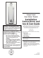
1
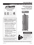
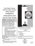
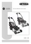
Direct Vent Gas Water Heater Installation Instructions and Use & Care Guide To obtain technical, warranty, or service assistance during or after the installation of this water heater, visit our website at: WARNING: If the information in these instructions is not followed exactly, a fire or explosion may result causing property damage, personal injury or death. Do not store or use gasoline or other flammable vapors and liquids in the vicinity of this or any other appliance. WHAT TO DO IF YOU SMELL GAS · · · · Do not try to light any appliance. Do not touch any electrical switch; do not use any phone in your building. Immediately call your gas supplier from a neighbors phone. Follow the gas suppliers instructions. If you cannot reach your gas supplier, call the fire department. Installation and service must be performed by a qualified installer, service agency or the gas supplier. http://www.americanwaterheater.com or call toll free: 1-800-999-9515 When calling for assistance, please have the following information ready: 1. Model number 2. 7 Digit product number 3. Serial number 4. Date of installation 5. Place of Purchase Table of Contents ................................................... 2 INSTALLER: AFFIX THESE INSTRUCTIONS TO OR ADJACENT TO THE WATER HEATER. OWNER: RETAIN THESE INSTRUCTIONS AND WARRANTY FOR FUTURE REFERENCE. RETAIN THE ORIGINAL RECEIPT AS PROOF OF PURCHASE. 6510238 January 2005 Supercedes 6510220 Your safety and the safety of others are very important. We have provided many important safety messages in this manual and on your appliance. Always read and obey all safety messages. This is the safety alert symbol. This symbol alerts you to potential hazards that can kill or hurt you and others. All safety messages will follow the safety alert symbol and either the word DANGER or WARNING. These words mean: You can be killed or seriously injured if you don't immediately follow instructions. You can be killed or seriously injured if you don't follow instructions. All safety messages will tell you what the potential hazard is, tell you how to reduce the chance of injury, and tell you what can happen if the instructions are not followed. Important Instructions · · Do not use this appliance if any part has been under water. Immediately call a qualified service technician. Water heaters subjected to flood conditions or anytime the gas controls, main burner or pilot have been submerged in water require replacement of the entire water heater. Hydrogen gas can be produced in a hot water system that has not been used for a long period of time (generally two weeks or more). Hydrogen gas is extremely flammable and can ignite when exposed to a spark or flame. To prevent the possibility of injury under these conditions, we recommend the hot water faucet be opened for several minutes at the kitchen sink before using any electrical appliance which is connected to the hot water system. If hydrogen is present, there will probably be an unusual sound such as air escaping through the faucet as water begins to flow. Do not smoke or have any open flame near the faucet at the time it is open. The California Safe Drinking Water and Toxic Enforcement Act requires the Governor of California to publish a list of substances known to the State of California to cause cancer, birth defects, or other reproductive harm, and requires businesses to warn of potential exposure to such substances. Warning: This product contains a chemical known to the State of California to cause cancer, birth defects, or other reproductive harm. This appliance can cause low-level exposure to some of the substances listed, including formaldehyde, carbon monxide, and soot. PAGE Table of Contents Water Heater Safety........................................................... 1-2 3-16 Installing Your Gas Water Heater............................ 3 Unpacking the Water Heater.................................. Location Requirements........................................... 4-5 Vent Cap Termination............................................ 5-6 Gas Supply.............................................................. 7-8 9 Combustion Air Supply and Ventilation.................. Vent Pipe System.................................................... 9-11 Water System Piping.............................................. 12-14 Special Applications.......................................... 15 Installation Checklist............................................... 16 Operating Your Water Heater............................................ 17-18 Lighting Instructions............................................................ 17-18 Operational Conditions........................................... 20 Maintenance of Your Water Heater........................ 21-24 Troubleshooting Chart........................................................ 25-26 Repair Parts Illustration............................................... 27-28 2 INSTALLING YOUR GAS WATER HEATER Consumer Information This water heater is design-certified by CSA International as a Category I, direct vented water heater which takes its combustion air from the outside of the structure and exhausts all products of combustion to the outside of the structure. This water heater must be installed according to all local and state codes or, in the absence of local and state codes, the National Fuel Gas Code, ANSI Z223.1(NFPA 54)- latest edition. This is available from the following: CSA America, Inc. 8501 East Pleasant Valley Road Cleveland, OH 44131 National Fire Protection Agency 1 Batterymarch Park Quincy, MA 02169-7471 Check your phone listings for the local authorities having jurisdiction over your installation. Consumer Responsibilities This manual has been prepared to acquaint you with the installation, operation, and maintenance of your gas water heater and provide important safety information in these areas. Read all of the instructions thoroughly before attempting the installation or operation of this water heater. Do not discard this manual. You or future users of this water heater will need it for future reference. The manufacturer and seller of this water heater will not be liable for any damages, injuries, or deaths caused by failure to comply with the installation and operating instructions outlined in this manual. If you lack the necessary skills required to properly install this water heater, or you have difficulty following the instructions, you should not proceed but have a qualified service technician perform the installation of this water heater. Examples of qualified service technicians include: those trained in the plumbing and heating industry, local gas utility personnel, or an authorized service person. Massachusetts code requires this water heater to be installed in accordance with Massachusetts Plumbing and Fuel Gas Code 248 CMR Section 2.00 and 5.00. A data plate identifying your water heater can be found next to the gas control valve/thermostat. When referring to your water heater, always have the information listed on the data plate readily available. Retain your original receipt as proof of purchase. Unpacking the Water Heater Use two or more people to move and install water heater unless proper handling equipment is utilized. Failure to do so can result in back or other injury. Removing Packaging Materials Important: Do not remove any permanent instructions, labels, or the data label from outside of the water heater or on the inside of panels. · Remove exterior packaging and place installation components aside. · · · Inspect all parts for damage prior to installation and start-up. Completely read all instructions before attempting to assemble and install this product. After installation, dispose of packaging material in the proper manner. 3 Figure 1: Residential Garage Installation Vehicle Stop Drain Pan Drain NOTE: In the State of California, the water heater must be braced, anchored, or strapped to avoid moving during an earthquake. Contact local utilities for code requirements in your area or call 1-800-999-9515 and request instructions. Site Location · This water heater design has been tested by CSA International and complies with ANSI Z21.10.1, Section 2.35 Flammable Vapors Resistance. Therefore this water heater does not need to be installed 18 inches above the floor unless specifically required by state or local codes. The water heater must be located or protected to avoid physical damage by vehicles or flooding. Do not use or store flammable products such as gasoline, solvents, or adhesives in the same room or area near the water heater. If such flammables must be used, all gas burning appliances in the vicinity must be shut off and their pilot lights extinguished. Open the doors and windows for ventilation while flammable substances are in use. If flammable liquids or vapors have spilled or leaked in the area of the water heater, leave the area immediately and call the fire department from a neighbor's home. Do not attempt to clean the spill until all ignition sources have been extinguished. 4 Select a location near the center of the water piping system. The water heater must be installed indoors and in a vertical position on a level surface. DO NOT install in bathrooms, bedrooms, or any occupied room normally kept closed. Note: The water heater may be installed in a closet with a door off a bedroom or bathroom providing the units are installed and vented per the manufacturers instructions. · Consider the vent piping and vent cap termination location. This is a direct vent water heater and may be vented through-the-wall. See Vent Cap Termination on pages 5-6 of this manual for the proper vent cap locations. · Locate the water heater near the existing gas piping. If installing a new gas line, locate the water heater to minimize the pipe length and elbows. Note: The water heater must be installed according to all local and state codes or, in absence of the local and state codes, the "National Fuel Gas Code, ANSI Z223.1 (NFPA 54)-latest edition. Important: The water heater should be located in an area where leakage of the tank or connections will not result in damage to the area adjacent to the water heater or to lower floors of the structure. Due to the normal corrosive action of the water, the tank will eventually leak after an extended period of time. Also any external plumbing leak, including those from improper installation, may cause early failure of the tank due to corrosion if not repaired. If the homeowner is uncomfortable with making the repair a qualified service technician should be contacted. A suitable metal drain pan should be installed under the water heater as shown below, to help protect the property from damage which may occur from condensate formation or leaks in the piping connections or tank. The pan must limit the water level to a maximum depth of 1-3/4 and be two inches wider than the heater and piped to an adequate drain. The pan must not restrict combustion air flow. Locate the water heater near a suitable indoor drain. Outside drains are subject to freezing temperatures which can obstruct the drain line. The piping should be at least 3/4 ID and pitched for proper drainage. Under no circumstances will the manufacturer or seller of this water heater be held liable for any water damage which is caused by your failure to follow these instructions. Figure 2: Minimun Clearance Locations Vent 0 Back 0 Sides 0 Top View Front 4 Inches Sides From 0 Combustibles Vent Cap Termination 1 3/4 Max Pipe to Adequate Drain At least 2 inches greater than the diameter of the water heater. · The water heater should be located in an area not subject to freezing temperatures. Water heaters located in unconditioned spaces (i.e., attics, basements, etc.) may require insulation of the water piping and drain piping to protect against freezing. The drain and controls must be easily accessible for operation and service. Maintain proper clearances as specified on the data plate. Clearances and Accessibility Notice: Minimum clearances from combustible materials are stated on the data plate adjacent to the thermostat of the water heater. · The water heater is certified for installation on a combustible floor. Important: If installing over carpeting, the carpeting must be protected by a metal or wood panel beneath the water heater. The protective panel must extend beyond the full width and depth of the water heater by at least 3 inches (76.2mm) in any direction or if in a alcove or closet installation, the entire floor must be covered by the panel. The panel must be strong enough to carry the weight of the heater when full of water. Figure 2 may be used as a reference guide to locate the specific clearance locations. A minimum of 24 inches of front clearance should be provided for inspection and service. The termination of the vent cap must be in accordance with the local code or the authority having jurisdiction, or in the absence of such, the National Fuel Gas Code, ANSI Z223.1, NFPA 54, Latest Edition. Do not terminate the vent cap in areas containing acid forming chemicals. Inlet air must not contain any corrosive elements. Any water heater failure due to corrosive elements in the atmosphere is excluded from warranty coverage. See Figures 3 and 4 for correct Vent Cap Termination Locations. Figure 3: Alcove Installation Minimums 18 Min. 18 Min. 24 Max. 5 Figure 4: Vent Cap Termination Locations U.S. Installation A. 12 in (30 cm) min. clearance above grade, veranda, porch, deck, balcony, or maximum anticipated snow level. B. 9 in (23 cm) min. clearance on top and side of window or door that may be opened. Do not install below a window or door that may be opened. C. Clearance to permanently closed window.** D. 12 in (30 cm) min vertical clearance to ventilated soffit. E. 12 in (30 cm) min. clearance to unventilated soffit. F. Clearance to outside corner ** G. 12 in (30 cm) min. clearance to inside corner formed by two exterior walls. H. 4 ft (122 cm) min. clearance to each side of center line extending above meter/regulator assembly. I. 4 ft (122 cm) min. clearance to service regulator vent outlet. J. 12 in (30 cm) min. clearance to nonmechanical air supply inlet to building or the combustion air inlet to any other appliance. K. 3 ft (91 cm) above if within 10 ft (3 m) horizontally of mechanical air supply inlet. **Clearance in accordance with local installation codes and the requirements of the gas supplier The Vent terminal is HOT when the water heater is in operation. Do not touch the vent terminal or place any object where contact with the vent terminal may occur. A protective louvered wall or fence is recommended when the hot vent cap is low enough to be touched accidentally (see Figure 5). A Vent guard kit (Kit # 6907245) may be ordered by contacting the manufacturer of this water heater at 1-800-999-9515. The exhaust outlet must not terminate under a patio, deck, or any covered area. Do not terminate the exhaust outlet near walkways or into alleys or other publicly accessible areas. Do not locate the vent terminal too close to shrubs or bushes. Caulk all cracks, seams, and joints within 6 feet horizontally above and below the vent. Do not terminate the vent within 12 inches of any other direct vented appliance vent 6 Figure 5: Protective Louvered Wall or Fence Hot Vent Cap HOT Protective Louvered Wall or Fence 3 feet Min. Explosion Hazard Use a new AGA or CSA approved gas supply line. Install a shut-off valve. Do not connect a natural gas water heater to a L.P. Gas Supply. Do not connect a L.P. gas water heater to a natural gas supply. Failure to follow these instructions can result in death, explosion, or carbon monoxide poisoning. Gas Requirements Read the data plate to be sure the water heater is made for the type of gas you will be using in your home. This information will be found on the data plate located near the gas control valve. If the information does not agree with the type of gas available, do not install or light. Call your dealer. Note: An odorant is added by the gas supplier to the gas used by this water heater. This odorant may fade over an extended period of time. Do not depend upon this odorant as an indication of leaking gas. Gas Piping Refer To Figure 6 1. Install a readily accessible manual shutoff valve in the gas supply line as recommended by the local utility. Know the location of this valve and how to turn off the gas to this unit. 2. Install a drip leg (if not already incorporated as part of the water heater) as shown. The drip leg must be no less than 3 inches long for the accumulation of dirt, foreign material and water droplets. 3. Install a ground joint union between the gas valve/thermostat and the manual shutoff valve. This is to allow easy removal of the gas valve/ thermostat. Figure 6: Gas Piping Manual gas shutoff valve Ground joint union Check with local utility for min. height 3 In. Min. Drip leg Gas Pressure Important: The gas supply pressure must not exceed the maximum supply pressure as stated on the water heaters data plate. The minimum supply pressure is for the purpose of input adjustment. The gas piping must be installed according to all local and state codes or, in absence of local and state codes, the National Fuel Gas Code, ANSI Z223.1 (NFPA 54)-latest edition. Tables 1 and 2 on page 8 are provided as a sizing reference for commonly used gas pipe materials. Consult the National Fuel Gas Code for the recommended gas pipe size of other materials. 7 Gas Pressure Testing Important: This water heater and its gas connection must be leak tested before placing the appliance in operation. · If the code requires the gas lines to be tested at a pressure exceeding 14 W.C., the water heater and its manual shutoff valve must be disconnected from the gas supply piping system and the line capped. · If the gas lines are to be tested at a pressure less than 14 W.C., the water heater must be isolated from the gas supply piping system by closing its manual shutoff valve. U.L. recognized fuel gas and carbon monoxide (CO) detectors are recommended in all applications and should be installed using the manufacturers instructions and local codes, rules, or regulations. Note: Air may be present in the gas lines and could prevent the pilot from lighting on initial start-up. The gas lines should be purged of air by a qualified service technician after installation of the gas piping system. Explosion Hazard Have a qualified person make sure L.P. gas pressure does not exceed 13 water column. Failure to do so can result in death, explosion, or fire. TABLE 1 NATURAL GAS PIPE CAPACITY TABLE (CU. FT./HR) Capacity of gas pipe of different diameters and lengths in cu. ft. per hr. with pressure drop of 0.3 in. and specific gravity of 0.60 (natural gas). Nominal Iron Pipe Size, in. 10 20 1/2 132 92 3/4 278 190 1 520 350 1-1/4 1050 730 1-1/2 1600 1100 30 73 152 285 590 890 40 63 130 245 500 760 50 56 115 215 440 670 60 50 105 195 400 610 Length of Pipe, Feet 70 80 90 46 43 40 96 90 84 180 170 160 370 350 320 560 530 490 100 38 79 150 305 460 125 34 72 130 275 410 150 31 64 120 250 380 175 28 59 110 225 350 200 26 55 100 210 320 After the length of pipe has been determined, select the pipe size which will provide the minimum cubit feet per hour required for the gas input rating of the water heater. By formula: Cu. Ft. Per Hr. Required = Gas Input of Water Heater (BTU/HR) Heating Value of Gas (BTU/FT³) The gas input of the water heater is marked on the water heater data plate. The heating value of the gas (BTU/FT3) may be determined by consulting the local natural gas utility. TABLE 2 LP GAS CAPACITY TABLE Maximum capacity of pipe in thousands of BTU per hour of undiluted liquefied petroleum gases (at 11 inches water column pressure). Based on a Pressure Drop of 0.5 Inch Water Column. Nominal Iron Pipe Size, in. 10 1/2 3/4 1 1-1/4 275 576 1071 2205 20 189 393 732 1496 30 152 315 590 1212 40 129 267 504 1039 50 114 237 448 913 Length of Pipe, Feet 60 70 80 103 96 89 217 196 185 409 378 346 834 771 724 90 83 173 322 677 100 78 162 307 630 125 69 146 275 567 Example: Input BTU requirement of the water heater, 100,000 BTUH Total pipe length, 80 feet = 3/4" IPS required. Additional tables are available in the latest edition of the "National Fuel Gas Code", ANSI Z223.1 8 150 63 132 252 511 Combustion Air Supply and Ventilation Figure 7: A & B Dimensions A B Important: Air for combustion and ventilation must not come from a corrosive atmosphere. Any failure due to corrosive elements in the atmosphere is excluded from warranty coverage. Vent Pipe System NOTE: 1. Dim. A measured from center of cutout to bottom of heater. 2. Dim. B measured from center of heater to outside of wall. This is a direct vent water heater which draws its combustion air from outside of the structure and exhausts all products of combustion to the outside of the structure. Through-the-wall installations require locating the water heater next to an outside wall. All necessary components are supplied for the standard through-the-wall installation. Optional vertical and horizontal extension kits are available for installations that exceed the standard horizontal and vertical distances (see table at right). Only one vertical and one horizontal kit can be used on the same installation. Through the Wall Venting 1. Make sure a proper location has been selected for the water heater installation. Consider the following: · · · · · Water piping Gas Piping Access for service Proper clearance for combustibles Drainage for the temperature and pressure relief valve and drain pan. · Vent cap termination 2. Determine the A dimension for your specific water heater by referencing figure 7. Cut a 6 inch opening through the wall in the location as shown. Determine the location of electrical wiring, pipes, or wall studs before cutting. NOTE: Installations requiring an A dimension (vertical height) greater than what is shown as standard in the table will require the use of a vertical extension kit (See Vertical Install Kit on Page 10). KIT CAPACITY 50 GALLON 40 GALLON STANDARD 62.75 HORIZONTAL A B B A 15.75 - 24.50 71.00 15.75 - 24.50 VERTICAL 27.00 - 38.00 62.75 62.75 - 89.75 15.75 - 24.50 71.00 71.00 - 98.00 27.00 - 38.00 15.75 - 24.50 BOTH 62.75 - 89.75 27.00 - 38.00 71.00 - 98.00 27.00 - 38.00 3. If you are not using the vertical extension kit, place the 3 elbow on the flue pipe reducer on the air box and point it in the desired direction (See Figure 8). Press it firmly downward until seated. Drill 4 holes 90° apart with a 1/8 drill bit and fasten the four #8 sheet metal screws provided. Apply silicone sealant to the joint. Install the 5 elbow over the 3 elbow and seat it into the collar on the air box. Drill 4 holes 90° apart with a 1/8 drill bit and fasten the four #8 sheet metal screws provided. Apply silicone sealant to the joint. Place the inner wall cover plate over the 5 elbow. This plate will be positioned later. Figure 8: Vertical Installation 5 Pipe 3 Elbow 1 Screws & Sealant 3 Elbow 2 Inside Cover Plate Screws & Sealant 9 4. Extend the 3 telescoping pipe to its maximum length. Place the smaller section onto the 3 elbow at least 1 and 1/2 inches (See Figure 9). Drill two holes 180° apart and secure with the two #8 sheet metal screws provided. Apply silicone sealant to the joint. 5. Attach the larger section of the 5 telescoping pipe to the flange on the outer wall plate (See Figure 9). Drill holes 90° apart with a 1/8 drill bit and fasten with four #8 sheet metal screws (provided). Apply silicone sealant to the seam. 6. Extend the 5 telescoping tube to its maximum length. From outside of the building, insert a 5 tube/outer wall plate assembly through the opening in the exterior wall and onto the 5 elbow (See Figure 9). Seat the base of the outer wall plate onto the exterior wall. Apply silicone sealant between the plate and the exterior wall. Figure 9: Vertical Installation Inner Wall Plate Screws & Sealant 3 Pipe Inner Wall Plate 5 Elbow 5 Telescoping Pipe Screws & Sealant 3 Telescoping Pipe Wall Slope down 1/4 per foot Screws Sealant HOT Screws ap C nt Ve Inner Wall Plate Outer Wall Plate Screws & Sealant 9. Position and fasten the inner wall plate to the inside wall using an appropriate fastener for the specific wall construction. Apply silicone sealant between the inner wall plate and the inside wall. 10. Make certain the 5 telescoping pipe has been fully engaged onto the 5 inch elbow. Drill two 1/8 holes 180° apart at the junction of the two joints. Secure with four #8 sheet metal screws and apply silicone sealant to the seams. Make sure all the 5 pipe joints are sealed including the joint to the collar on the water heaters air supply box (See Figure 9). Optional Vertical Extension Kit 3 Telescoping Pipe Outer Wall Plate 7. Place the 3 tube located in the vent cap into the end of the 3 telescoping tube (See Figure 10). Drill two holes 180° apart with a 1/8 drill bit and secure with two #8 sheet metal screws. Apply sealant to the joint. Seat the cap against outer wall plate with the word HOT in an upright position. 8. Secure the vent cap/outer wall plate assembly to the exterior wall with the four 1 and 1/2 screws provided (See Figure 10). Varying wall structures may require a different type of screw anchor. To prevent rain from entering the water heater vent pipe, the 5 tube should be sloped downward towards the wall 1/4 per foot. 10 Figure 10: Vertical Installation Installations requiring dimension "A" to be greater than 62.75 (40 Gallon) or 71.00 (50 Gallon) will require the use of the optional vertical extension kit. The maximum height of the "A" dimension cannot exceed 98 inches. If the "A" dimension for your application is less than 98 inches, you will have to cut the 3 and 5 inch pipes in the vertical extension kit to the correct length. For example, if your applicable "A" distance is 80 inches, then 98 inches - 80 inches = 18 inches. Therefore, you will need to cut 18 inches from both the 3 and 5 inch vertical extension pipes. DO NOT CUT THE CRIMPED END OF THE 5 INCH PIPE. After cutting both the pipes to the proper size, place the 3 vertical extension pipe over the flue pipe reducer on the upper air box and press it firmly downward until seated. Using a level, make sure the extension tube is pointing straight up. Drill 4 holes 90° apart with a 1/8 drill bit and fasten with four #8 sheet metal screws (provided). Apply silicone sealant to the seam. Place the uncrimped end of the 5 inch extension pipe over the 3 inch extension pipe and seat it onto the collar on the air box. Making sure the 3 inch extension pipe is centered in the 5 inch pipe, drill four holes 90° apart with the 1/8 drill bit and fasten with four #8 sheet metal screws (provided). Apply silicone sealant to the seam. Place the flared end of the 3 inch elbow over the 3 inch extension pipe and press it firmly downward until seated. Drill four holes 90° apart with the 1/8 drill and fasten with four #8 sheet metal screws (provided). Apply silicone sealant to the seam. Install the 5 inch elbow over the 3 inch elbow and seat it down onto the crimped end of the 5 inch extension pipe. Temporarily place the 5 inch telescoping pipe onto the 5 inch elbow and adjust it to give a 1/4 inch per foot downward slope to the outside wall. Secure the 5 inch elbow to the extension pipe by drilling four holes 90° apart with the 1/8 drill and inserting four #8 sheet metal screws. Apply silicone sealant to the joint. Place the inner wall cover plate over the 5 inch elbow. This plate will be positioned later. Proceed to step 4. THROUGH THE ROOF VENTING* 1. Center the heater directly under the roof opening. This vent system must be installed vertically only. 2. All the pipes needed to assemble the vent are included in the kit. Do not add to the length of the vent system. The total height is limited to 15 feet on a 50-gallon heater (See Figure 11). The 40-gallon heater is 8 and1/4 shorter. The total 15-foot height must stick through the roof a minimum of 2 feet. If the height needed is less than 15 feet, determine the height needed and subtract that from 15 feet. That amount needs to be cut off one of the 3 pipes and 5 pipes. Cut the non-flared end of the 3 pipe and the uncrimped end of the 5 pipe. 3. Assemble the kit from the top down starting with the termination. Attach a 3 pipe using 4 #8 sheet metal screws 90° apart and seal the joint with sealant. Then attach the 5 section in the same manor. Drill 1/8 pilot holes for the screws. Continue until the full length is assembled. Put the telescoping 5 section on last. 4. Place the heater in position, feed the vent assembly down through the roof with the flashing in place, and allow it to rest with the 3 pipe attached to the 3 vent terminal on the heater. Use screws and sealant to secure that joint. Extend the 5 telescoping section to connect to the 5 termination on the heater. Secure that joint with screws. Seal that joint and the sliding joint with silicone to make an airtight assembly. 5. Secure the flashing and vent assembly to the roof. (*Through the Roof Venting Kit available from manufacturer) Figure 11: Through the Roof Venting Roof Jack Assembly Roof Flashing 2 Ft. Min. From Any Object within A 10 Foot Horizontal Radius 8 Ft. Min. 15 Ft. Max Secure All Connections with Screws and Apply Silicone Sealant 11 Water System Piping 7. After piping has been properly connected to the water heater, remove the aerator at the nearest hot water faucet. Open the hot water faucet and allow the tank to completely fill with water. To purge the lines of any excess air, keep the hot water faucet open for 3 minutes after a constant flow of water is obtained. Close the faucet and check all connections for leaks. Piping Installation Piping, fittings, and valves should be installed according to the installation drawing (Figure 12). If the indoor installation area is subject to freezing temperatures, the water piping must be protected by insulation. Water supply pressure should not exceed 80% of the working pressure of the water heater. The working pressure is stated on the water heaters data plate. If this occurs a pressure limiting valve with a bypass may need to be installed in the cold water inlet line. This should be placed on the supply to the entire house in order to maintain equal hot and cold water pressures. Important: Heat cannot be applied to the water fittings on the heater as they may contain nonmetallic parts. If solder connections are used, solder the pipe to the adapter before attaching the adapter to the hot and cold water fittings. Important: Always use a good grade of joint compound and be certain that all fittings are drawn up tight. 1. Install the water piping and fittings as shown in Figure 12. Connect the cold water supply (3/4 NPT) to the fitting marked C. Connect the hot water supply (3/4 NPT) to the fitting marked H. Important: Some models may contain energy saving heat traps to prevent the circulation of hot water within the pipes. Do not remove the inserts within the heat traps. 2. 3. 4. 5. 6. 12 The installation of unions in both the hot and cold water supply lines is recommended for ease of removing the water heater for service or replacement. The manufacturer of this water heater recommends installing a tempering valve or an anti-scald device in the domestic hot water line as shown in Figure 13. These valves reduce the point of use temperature of the water by mixing cold and hot water and are readily available for use. Contact a licensed plumber or the local plumbing authority. If installing the water heater in a closed water system, install an expansion tank in the cold water line as specified under Closed System/Thermal Expansion (Page 13). Install a shut-off valve in the cold water inlet line. It should be located close to the water heater and be easily accessible. Know the location of this valve and how to shut off the water to the heater. Install a temperature and pressure relief valve in the opening marked Temperature and Pressure (T & P) Relief Valve on the water heater. Add a discharge line to the opening of the T & P relief valve. Follow the instructions under Temperature and Pressure Relief Valve" (Page 14). Figure 12: Water Piping Installation In a Closed System Use a Thermal Expansion Tank Cold Water Supply to Fixtures Hot Water Outlet Main Water Supply Cold Water Inlet Valve Union Pressure Reducing Valve with Bypass Temperature and Pressure Relief Valve Discharge Line 6 Inches Maximum Above Drain Drain Line 3/4 Inch ID Minimum Drain 1 Inch Min. Metal Drain Pan 1 3/4 Inch Depth Max. Massachusetts: Install a vacuum relief in cold water line per section 19 MGL 142. Figure 13: Typical Tempering Valve Installation Follow the tempering Valve manufacturers Instructions Cold Water Inlet Hot Water Outlet Tempered water to fixtures Tempering Valve (Set to 120°F) Please note the following: DO NOT install this water heater with iron piping. The system should be installed only with piping that is suitable for potable (drinkable) water such as copper, CPVC, or polybutylene. DO NOT use PVC water piping. DO NOT use any pumps, valves, or fittings that are not compatible with potable water. DO NOT use valves that may cause excessive restriction to water flow. Use full flow ball or gate valves only. DO NOT use 50/50 tin-lead solder (or any lead based solder) in potable water lines. Use 95/5 tin-antimony or other equivalent material. DO NOT tamper with the gas valve/thermostat, igniter, thermocouple, or temperature and pressure relief valve. Tampering voids all warranties. Only qualified technicians should service these components. DO NOT use with piping that has been treated with chromates, boiler seal, or other chemicals. DO NOT add any chemicals to the system piping which will contaminate the potable water supply. Closed System/Thermal Expansion Periodic discharge of the temperature and pressure relief valve may be due to thermal expansion in a closed water supply system. The water utility supply meter may contain a check valve, backflow preventer or water pressure reducing valve. This will create a closed water system. During the heating cycle of the water heater, the water expands causing pressure inside the water heater to increase. This may cause the temperature and pressure relief valve to discharge small quantities of hot water. To prevent this, it is recommended that a diaphragm-type expansion tank (suitable for potable water) be installed on the cold water supply line. The expansion tank must have a minimum capacity of 1.5 U.S. gallons for every 50 gallons of stored water. Contact the local water supplier or plumbing inspector for information on other methods to control this situation. Important: Do not plug or remove the temperature and pressure relief valve. 13 Temperature and Pressure Relief Valve Explosion Hazard If the temperature and pressure relief valve is dripping or leaking, have a licensed plumber correct the problem. Do not plug valve. Do not remove valve. Failure to follow these instructions can result in death, or explosion. Figure 14: T & P Valve Installation Temperature and Pressure Relief Valve Discharge Line 3/4 Inch Min. DO NOT CAP OR PLUG Drain pan 6 inch maximum Drain For protection against excessive pressures and temperatures, a temperature and pressure relief valve must be installed in the opening marked T & P RELIEF VALVE (see Figure 14). This valve must be design certified by a nationally recognized testing laboratory that maintains periodic inspection of the production of listed equipment or materials as meeting the requirements for Relief Valves and Automatic Shut-off Devices for Hot Water Supply Systems, ANSI Z21.22. The function of the temperature and pressure relief valve is to discharge water in large quantities in the event of excessive temperature or pressure developing in the water heater. The valve's relief pressure must not exceed the working pressure of the water heater as stated on the data plate. 14 Important: Only a new temperature and pressure relief valve should be used with your water heater. Do not use an old or existing valve as it may be damaged or not adequate for the working pressure of the new water heater. Do not place any valve between the relief valve and the tank. The Temperature & Pressure Relief Valve: · Must not be in contact with any electrical part. · Must be connected to an adequate discharge line. · Must not be rated higher than the working pressure shown on the data plate of the water heater. The Discharge Line: · Must not be smaller than the pipe size of the relief valve or have any reducing coupling installed in the discharge line. · Must not be capped, blocked, plugged or contain any valve between the relief valve and the end of the discharge line. · Must terminate a maximum of 6 inches above a floor drain or external to the building. · Must be capable of withstanding 250°F (121°C) without distortion. · Must be installed to allow complete drainage of both the valve and discharge line. Special Applications Combination Space Heating/ Potable Water System Some water heater models are equipped with inlet/outlet tappings for use with space heating applications. If this water heater is to be used to supply both space heating and domestic potable (drinking) water, the instructions listed below must be followed. · Be sure to follow the manual(s) shipped with the air handler system. · This water heater is not to be used as a replacement for an existing boiler installation. · Do not use with piping that has been treated with chromates, boiler seal or other chemicals and do not add any chemicals to the water heater piping. · If the space heating system requires water temperatures in excess of 120°F, a tempering valve or an anti-scald device should be installed per its manufacturers instructions in the domestic (potable) hot water supply to limit the risk of scald injury. · Pumps, valves, piping and fittings must be compatible with potable water. · A properly installed flow control valve is required to prevent thermosiphoning. Thermosiphoning is the result of a continuous flow of water through the air handler circuit during the off cycle. Weeping (blow off) of the temperature and pressure relief valve (T & P) or higher than normal water temperatures are the first signs of thermosiphoning. · The domestic hot water line from the water heater should be vertical past any tempering valve or supply line to the air handler to remove air bubbles from the system. Otherwise, these bubbles will be trapped in the air handler heat exchanger coil, reducing the efficiency. · Do not connect the water heater to any system or components previously used with non-potable water heating appliances when used to supply potable water. Figure 15: Space Heating Piping Installation Domestic Hot Water Out Tempering Valve Must Be Vertical To Remove Air Bubbles Cold Water Inlet Pump Hot Water Out Unions Flow Control Valve Out In Coil To Air Handler Air Handler Shut Off Valve Typical tempering valve installation Combination space heating/ potable water heating system Massachusetts Code does not allow this type of installation. Solar Installation If this water heater is used as a solar storage heater or as a backup for the solar system, the water supply temperatures to the water heater tank may be in excess of 120°F. A tempering valve or other temperature limiting valve must be installed in the water supply line to limit the supply temperature to 120°F. Note: Solar water heating systems can often supply water with temperatures exceeding 180°F and may result in water heater malfunction. IMPORTANT: Water supply to this heater must not exceed 180°F. Water temperature in excess of 180°F will cause the High Limit Control to open and shut off the gas supply to the unit. The High Limit Control is a single use type that will require the replacement of the thermostat before the burner will operate. Some jurisdictions may require a backflow preventer in the incoming cold water line. This may cause the temperature and pressure relief valve on the water heater to discharge or weep due to expansion of the heated water. A diaphragm-type expansion tank suitable for potable water will normally eliminate this weeping condition. Please read and follow the manufacturers instructions for the installation of such tanks. Also see Water System Piping (Page 12) for additional instructions on the safe and correct installation and operation of this water heater. 15 INSTALLATION CHECKLIST Water Heater Location · · · · · · · Centrally located with the water piping system. Located as close to the gas piping and vent pipe system as possible. Located indoors and in a vertical position. Protected from freezing temperatures. Proper clearances from combustible surfaces maintained and not installed directly on a carpeted floor. Provisions made to protect the area from water damage. Drain pan installed and piped to an adequate drain. Installation area free of corrosive elements and flammable materials. Sufficient room to service the water heater. Water heater not located near an air moving device. Gas Supply and Piping · · · · · 16 Gas supply is the same type as listed on the water heater data plate. Gas line equipped with shut-off valve, union and drip leg. Approved pipe joint compound used. Adequate pipe size and of approved material. Chloride-free soap and water solution or other approved means used to check all connections and fittings for possible gas leaks. Combustion Air Supply and Ventilation · Must not come from a corrosive atmosphere. Vent Pipe System · · · · · Proper location on an outside wall selected for Through the Wall Venting. A Dimensions determined per water heater to determine whether a Vertical Extension kit is needed. Optional Vertical Extension Kit Installed (if necessary). Heater centered directly under the roof opening for Through the Roof Venting. Through the roof venting has a 15 foot maximum height for the 50 Gallon direct vent water heater and a maximum of 14 3-1/4 for the 40 Gallon direct vent water heater. Water System Piping · · · · · Temperature and pressure relief valve properly installed with a discharge line run to an open drain and protected from freezing. All piping properly installed and free of leaks. Heater completely filled with water. Closed system pressure build-up precautions installed. Tempering valve installed per manufacturers instructions. OPERATING YOUR WATER HEATER Lighting Instructions Read and understand these directions thoroughly before attempting to light or re-light the pilot. Make sure the tank is completely filled with water before lighting the pilot. Check the data plate near the gas valve control/thermostat for the correct gas. Do not use this water heater with any gas other than the one listed on the data plate. If you have any questions or doubts, consult your gas supplier or gas utility company. Explosion Hazard Replace viewport if glass is missing or damaged. Failure to do so can result in death, explosion or fire. LIGHTING INSTRUCTIONS 1. Remove the outer door. 2. Turn the temperature dial counterclockwise lowest setting. 130° F BAR RESET BUTTON to its 120° F BAR INDEX BARS 130° F BAR 6. Depress the reset button all the way in and IMMEDIATELY depress the igniter button until you hear a loud click. Observe the pilot through the view port. Do not release the reset button. Repeat immediately if pilot does not light on the first try. If the pilot does not light by the fourth attempt with the igniter, repeat steps 3 - 6. Continue to hold the button for about (1) minute after the pilot is lit. Release the reset button and it will pop back up. Pilot should remain lit. If the pilot light goes out, repeat steps 2 - 6. IGNITER IMPORTANT: If the pilot will not stay lit after several tries, turn gas control knob to "OFF" and call your service technician or gas supplier. 3. Turn gas control knob clockwise to the OFF" position. 4. To clear any gas that may have accumulated wait ten (10) minutes. If you then smell gas, STOP! Refer to the safety warning on the cover. If you do not smell gas go to the next step. 5. Turn the gas control knob counterclockwise to "PILOT". IMPORTANT: If the reset button does not pop up when released, stop and immediately shut off the gas at the line valve or tank. Call your service technician or gas supplier. 7. Turn the gas control knob counterclockwise to "ON". 8. Set the temperature dial to the desired setting. 9. Replace the outer door. TO TURN OFF GAS TO APPLIANCE 1. Turn the temperature dial counterclockwise lowest setting. to its 2. Turn the gas control knob clockwise position. to the "OFF" 17 L.P.G. (Bottled Propane) Models Liquefied Petroleum Gas is over 50% heavier than air and in the occurrence of a leak in the system, the gas will settle on the floor level. Basements, crawl spaces, skirted areas under mobile homes (even when ventilated), closets and areas below ground level will serve as pockets for the accumulation of gas. Before lighting, smell all around the appliance at floor level. If you smell gas, follow the instructions as given in the warning on the front page. See the instructions below on lighting the L.P. Direct Vent gas water heater. When the unit fails to operate properly because the L.P. tank is low on fuel or the outside temperature is very cold, turn off the gas at all gas appliances including the pilot lights. After the tank is refilled, all appliances must be re-lit according to their manufacturers instructions. LIGHTING INSTRUCTIONS 1. Remove the outer door. 2. Turn the temperature dial counterclockwise lowest setting. 130° F BAR T S T S RY SE JU T C A HO RY SE JU N I N D N CA T W N HA IO T SCA L CA T OF VA HO E M HO T T ER A I N C RE ER W C A R T WA I R HA 130° F BAR W R VA I SK S N S D SCA L RT O RT OF T HE E M HO T T ER ER A I N C RE T WA I R T HE R OB E SK R R U T I INDEX BAR W R OB E P E RA T U A E M U T I N READ ALL INSTRUCTIONS BEFORE LIGHTING P E RA T U O CAUTION M A E WARNING 120° F BAR ON 3. Turn gas control knob clockwise to the OFF position. IMPORTANT: If the pilot will not stay lit after several tries, turn gas control knob to OFF and call your service technician or gas supplier. PI LO T O F F 4. To clear any gas that may have accumulated wait ten (10) minutes. If you then smell gas, STOP! Refer to the safety instructions on the cover. If you do not smell gas go to the next step. PILOT 7. Turn the gas control knob counterclockwise to ON. ON P IL 8. Set the temperature dial to the desired setting. FF N O 5. Turn the gas control knob counterclockwise to PILOT. IMPORTANT: If the gas control knob does not pop up when released, stop and immediately shut off the gas at the line valve or tank. Call your service technician or gas supplier. OF F OF F P I LOT IO ON IGNITER OT GAS CONTROL KNOB to its 6. Depress the gas control knob all the way in and IMMEDIATELY depress the igniter button until you hear a loud click. Observe the pilot through the view port. Do not release the gas control knob. Repeat immediately if pilot does not light on the first try. If the pilot does not light by the fourth attempt with the igniter, repeat steps 4 - 7. Continue to hold the knob for about (1) minute after the pilot is lit. Release the gas control knob and it will pop back up. Pilot should remain lit. If the pilot light goes out, repeat steps 3 - 7. O 9. Replace the outer door. TO TURN OFF GAS TO APPLIANCE 1. Turn the temperature dial counterclockwise lowest setting. 18 to its 2. Turn the gas control knob clockwise position. to the OFF GAS CONTROL KNOB RO VAC A 130° F BAR N Figure 17B: Robert Shaw Gas Valve/Thermostat Settings (L.P.) S N S RY SE JU I N T W IO T T T RY JU N W SE HA OF SCA L D CA T HO T T ER A I N C RE ER VA HO M N C A W R O T WA RI SK S CA T D VA HA SCA L RT N S OF I U T I T HE O HO T T ER A I N C RE ER 130° F BAR R OB E E M RT T WA I R T HE R OB E SK R R U T I INDEX BAR W A E P E RA T U M P E RA T U E READ ALL INSTRUCTIONS BEFORE LIGHTING M R E A CAUTION 120° F BAR 130° F BAR REMOVABLE REGULATOR CAP OF F P I LOT C A ON HO GAS CONTROL KNOB WARNING Water temperature over 125°F can cause severe burns instantly or death from scalds. Children, disabled and elderly are at highest risk of being scalded. See instructions manual before setting temperature at water heater. Feel water before bathing or showering. Temperature limiting valves are available. H TE OTTER S RI R INCREA J SK IN OF SCALD A W E TH INDEX BARS ES UR Y L VACA TIO Water Temperature Regulation HOT IT N Important: Should overheating occur or the gas supply fails to shut off, turn off the water heaters manual gas control valve and call a qualified service technician. M UN WA R ION UT CA RE BE AD WA FO AL R RE L IN NIN ST G RU CT LIG HIO NS TIN G T O CAU TI O Emergency Shut Down 120° F BAR 130° F BAR RESET BUTTON RM A W Stacking occurs when a series of short draws of hot water (3 gallons or less) are taken from the water heater tank. This causes increased cycling of the burner and can result in increased water temperatures at the hot water outlet. An anti-scald device is recommended in the hot water supply line to reduce the risk of scald injury. Figure 17A: Robert Shaw Gas Valve/Thermostat Settings (Natural) H Stacking N Inspect the burner flames through the This may have a yellow tint viewport and compare them to the drawings in Yellow inner cones are Figure 16. A properly satisfactory operating burner should produce a soft Incorrect flame Correct flame blue flame. Blue tips lazy yellow soft blue with yellow inner cones are satisfactory. The tips of the flame may have a slight yellow tint. The flame should not be all yellow or have a sharp blue-orange color. Contaminated air may cause an orange colored flame. Contact a qualified service technician if the flame is not satisfactory. The thermostat is adjusted to its lowest temperature when it is shipped from the factory. Water temperature can be regulated by moving the temperature dial to the preferred setting. The preferred starting point is 120°F. Align the index bar on the thermostat with the desired water temperature as shown in Figures 17A and 17B. There is a hot water scald potential if the thermostat is set too high. Important: Adjusting the thermostat past the 120°F bar on the temperature dial will increase the risk of scald injury. Hot water can produce first degree burns within: 120°F (49°C) more than 5 minutes 130°F (54°C) at 20 seconds 140°F (60°C) at 3 seconds 150°F (66°C) at 1-1/2 seconds 160°F (71°C) at less than 1 second IO Figure 16: Flame Characteristics ON TI Burner Flames Note: During low demand periods when hot water is not being used, a lower thermostat setting will reduce energy losses and may satisfy your normal hot water needs. If hot water use is expected to be more than normal, a higher thermostat setting may be required to meet the increased demand. When leaving your home for extended periods (vacations, etc.) turn the temperature dial to its lowest setting. This will maintain the water at low temperatures with minimum energy losses and prevent the tank from freezing during cold weather. 19 Operational Conditions Condensation Moisture from the products of combustion condenses on the tank surface and the outside jacket of the water heater and forms drops of water which may fall onto the burner or other hot surfaces. This will produce a sizzling or frying noise. This condensation is normal and should not be confused with a leaking tank. Condensation may increase or decrease at different times of the year. High efficient energy saver water heaters will produce larger amounts of condensation on initial start up or when a large amount of hot water is being used. Do not confuse this with a tank leak. Once the water reaches a temperature of 120°F and the tank warms up (usually 1-2 hours), the condensation will stop. Important: It is always recommended that a suitable drain pan be installed under the water heater to protect the area from water damage resulting from normal condensation production or a leaking tank or piping connections. Refer to the Location Requirements on page 4-5. Under no circumstances is the manufacturer to be held responsible for any water damage in connection with this water heater. Water Heater Sounds During the normal operation of the water heater, sounds or noises may be heard. These noises are common and may result from the following: 1. Normal expansion and contraction of metal parts during periods of heat-up and cool-down. 2. Condensation causes sizzling and popping within the burner area and should be considered normal. 3. Sediment buildup in the tank bottom will create varying amounts of noise and may cause premature tank failure. Drain and flush the tank as directed under Draining and Flushing. Smoke/Odor The water heater may give off a small amount of smoke and odor during the initial start-up of the unit. This is due to the burning off of oil from the metal parts of a new unit and will disappear after a few minutes of operation. Safety Shut-off This water heater is designed to automatically shut-off in the event of the following: 1. The pilot flame is extinguished for any reason. 2. The water temperature exceeds 180°F (83°C). 20 A thermocouple is used to determine if a pilot flame is present and will shut off the gas supply to the main burner and the pilot burner if the flame is absent. A high temperature limit switch or ECO (Energy Cut Off) in the tank is used to shut off the unit if the water temperature exceeds 180°F (83°C). The ECO is a single use switch and requires complete replacement of the entire thermostat. If the ECO should function, the water heater cannot be used until the thermostat is replaced by a qualified service agency. Contact your local dealer for service information. Anode Rod/Water Odor Each water heater contains at least one anode rod, which will slowly deplete while protecting the glass-lined tank from corrosion and prolonging the life of the water heater. Certain water conditions will cause a reaction between this rod and the water. Once the anode is depleted, the tank will start to corrode, eventually developing a leak. The most common complaint associated with the anode rod is a rotten egg smell produced from the presence of hydrogen sulfide gas dissolved in the water. Do not remove this rod permanently as it will void any warranties, stated or implied. The parts list includes a special anode that can be ordered if water odor or discoloration occurs. This rod may reduce but not eliminate water odor problems. The water supply system may require special filtration equipment from a water conditioning company to successfully eliminate all water odor problems. Artificially softened water is exceedingly corrosive because the process substitutes sodium ions for magnesium and calcium ions. The use of a water softener may decrease the life of the water heater tank. The anode rod should be removed from the water heater tank every 3 years for inspection. If the rod is more than 50% depleted, the anode rod should be replaced. In replacing the anode: 1. Turn off gas supply to the water heater. 2. Shut off the water supply and open a nearby hot water faucet to depressurize the water tank. 3. Drain approximately 5 gallons of water from tank (Refer to Draining and Flushing for proper procedures). Close drain valve. 4. Remove old anode rod. 5. Use Teflon® tape or approved pipe sealant on threads and install new anode rod. 6. Turn on water supply and open nearby hot water faucet to purge air from water system. 7. Restart the water heater as directed under Operating Your Water Heater. See the "Repair Parts Illustration" for anode rod location on page 27. MAINTENANCE OF YOUR WATER HEATER Draining and Flushing It is recommended that the tank be drained and flushed every 6 months to remove sediment which may buildup during operation. The water heater should be drained if being shut down during freezing temperatures. To drain the tank, perform the following steps: 1. Turn off the gas to the water heater at the Manual Gas Shutoff Valve. 2. Close the cold water inlet valve. 3. Open a nearby hot water faucet. 4. Connect a hose to the drain valve and terminate it to an adequate drain. Note: The drain hose should be rated for at least 200°F. If the drain hose does not have this rating, open the cold water inlet valve and a nearby hot faucet until the water is no longer hot. 5. Open the water heater drain valve and allow all the water to drain from the tank. Flush the tank with water as needed to remove sediment. 6. Close the drain valve, refill the tank, and restart the heater as directed under Operating Your Water Heater. If the water heater is going to be shut down for an extended period, the drain valve should be left open. Important: Condensation may occur when refilling the tank and should not be confused with a tank leak. 3 Month Inspection At least every 3 months, a visual inspection should be made of the venting and air supply system, piping systems, main burner and pilot burner. Check the water heater for the following: · Obstructions, damage, or deterioration in the venting system. Make sure the ventilation and combustion air supplies are not obstructed. · Buildup of soot and carbon on the main burner and pilot burner. Check for a soft blue flame. · Leaking or damaged water piping or gas piping. · Presence of flammable or corrosive materials in the installation area. · Presence of combustible materials near the water heater. Important: Verify proper operation after servicing this water heater. Temperature and Pressure Relief Valve Explosion Hazard If the temperature and pressure relief valve is dripping or leaking, have a licensed plumber correct the problem. Do not plug valve. Do not remove valve. Failure to follow these instructions can result in death, or explosion. Manually operate the temperature and pressure relief valve at least once a year Figure 18 to make sure it is working Temperature and properly. To prevent water Pressure Relief Valve Manual Relief damage, the valve must be Valve properly connected to a discharge line which terminates at an adequate drain. Standing clear of the outlet (discharged water may be Discharge Line to Drain hot), slowly lift and release the lever handle on the temperature and pressure relief valve to allow the valve to operate freely and return to its closed position. If the valve fails to completely reset and continues to release water, immediately shut off the manual gas valve and the cold water inlet valve and call a qualified service technician. Self-cleaning (Some Models) Some water heaters may include a self-cleaning device that inhibits the buildup of lime and other sediment on the metal surfaces of the water heater. As cold water passes through the dip tube, lime-causing particles and minerals are suspended automatically. This controls sediment and lime buildup within the tank and results in higher efficiencies and lower operation costs. 21 Replacement Parts Replacement parts may be ordered through your plumber or the local distributor. Parts will be shipped at prevailing prices and billed accordingly. When ordering replacement parts, always have the following information ready: 1. Model, serial and product number. 2. Type of gas. 3. Item number. 4. Parts Description. See page 27 for a list of available repair parts. Removing the Manifold Assembly 1. 2. 3. 4. Turn off the gas to the water heater at the manual shutoff valve (Figure 6). Turn the gas control knob on the combination gas control valve/thermostat clockwise to the OFF position (Figure 17). Figure 19 Remove the outer door. Remove the (6) screws securing the manifold door assembly to the skirt (Figure 20). Disconnect the thermocouple, pilot tube, igniter wire, and manifold tube (L.P. Igniter Wire models have left-hand threads) at the thermostat. (Figure 19). Thermocouple Pilot tube UNITROL WARNING Removing the Burner from the Manifold Assembly 1. 2. Turn the burner counterclockwise to remove it from the manifold assembly. Check the burner to see if it is dirty or clogged. The burner may be cleaned with soap and hot water (Figure 21A). Figure 21A: Natural Gas Burner Assembly Burner Two Piece Wire Connector Manifold Door Gasket Thermocouple Igniter Wire Thermocouple Retainer Clip Manifold Tube Pilot Tube Viewport Pilot Assembly Pilot Bracket To Remove Burner Manifold Door Assembly READ ALL INSTRUCTIONS BEFORE LIGHTING W A T S SE JU N I CA T D SCA L VA OF L.P. Gas Burner RY N HO T T ER A I N C RE ER W IO HO C A O HA N 7. M SK S 6. R RT T WA I R T HE R OB E 5. U T I Grasp the manifold tube Manifold Tube and push down slightly to free the manifold, pilot tube, and thermocouple. Carefully remove the manifold assembly from the burner compartment. Be sure not to damage internal parts. 1. Separate the pilot bracket from the L.P. burner by removing screw. 2. Loosen set screw located on top of the L.P. burner near the manifold door. Carefully, pull the burner away from the manifold door assembly. 3. Check the burner to see if it is dirty or clogged. The burner may be cleaned with soap and hot water (Figure 21B). Figure 21B: L.P. Gas Burner Assembly Thermocouple/ Igniter Connector Figure 20: Burner Assembly Removal Gas Valve / Thermostat Piezo Igniter Button Pilot Tube UNITROL WARNING T Drain Valve HA S D Manifold Tube RY SE JU I N SCA L W N S OF Thermocouple CA T RT HO T T ER A I N C RE ER Gasket Igniter Wire VA T WA I R T HE R OB E N SK IO HO C A O 22 U T I M Screw (6 Places) W R Thermocouple READ ALL INSTRUCTIONS BEFORE LIGHTING A Manifold Tube Manifold Door Assembly Viewport Manifold Door Assembly Two Piece Wire Connector Pilot Tube Pilot Assembly (Piezo Igniter, Thermocouple, Pilot) Burner Replacing the Thermocouple Important: Use only a factory authorized thermocouple for replacement. 1. Remove the manifold assembly as directed previously. 2. Remove the retainer clip from the back of the two piece wire connector. Remove the two piece wire connector from the manifold door. Remove the thermocouple (Figure 22). 3. Pull the thermocouple from the pilot assembly. (Figure 21 and 24). 4. Push the new thermocouple through the holes in the pilot bracket. (Thermocouple tube must be positioned below the pilot bracket.) Insert the thermocouple tube into the holes provided in the pilot assembly until it clicks into place. 5. Position the new thermocouple through the larger opening of the two piece wire connector (Figure 22). Be sure igniter wire is positioned through the small opening of the two piece wire connector. 6. See Replacing Manifold Assembly at the top of next column. Figure 22: Two Piece Wire Connector Assembly Thermocouple Igniter Wire Other fittings not shown for clarity Replacing the Manifold Assembly Explosion Hazard Tighten manifold door screws securely. Remove any fiberglass between gasket and combustion chamber. Replace viewport if glass is missing or damaged. Replace two piece wire connector if missing or removed. Replace door gasket if damaged. Failure to do so can result in death, explosion, or fire. 1. 2. Retainer Clip Manifold Door 3. Two Piece Wire Connector 4. Check the door gasket for damage or imbedded debris prior to installation. Insert the manifold Figure 23 assembly into the burner compartment making sure that tip of the manifold tube engages with the slot in the bracket inside the combustion chamber (Figure 23). Inspect the door gasket and make sure there is no fiberglass insulation between the gasket and the combustion chamber. Inspect the viewport for damage and replace as required. 23 5. Replace the (6) screws which secure the manifold assembly door to the combustion chamber. Tighten securely. There should be no space between the gasket part of the manifold door and combustion chamber. Do not operate the water heater if the door gasket is not sealed. Reconnect the manifold tubing (L.P. models have lefthand threads), pilot tubing, and thermocouple to the thermostat. Do not cross-thread or apply any thread sealant to these fittings. The thermocouple nut should be started and turned all the way in by hand. An additional quarter turn with a 3/8 open-end wrench will then be sufficient to seat the lockwasher. Reconnect the igniter wire. Turn gas supply on and refer to the "Lighting Instructions" on page 17-18. Check for leaks. Use a chloride-free soap and water solution (bubbles forming indicate a leak) or other approved method. All leaks must be fixed immediately. 6. 7. 8. 9. 10. Replace the outer door. Piezoelectric Igniter System The piezoelectric igniter system consists of the igniter button, electrode and wire. The pilot is ignited by an electric spark generated when the igniter button is pressed. The spark gap of 0.125 inch is set when the electrode is installed at the factory. (See Figure 24A and 24B). Use only factory authorized piezoelectric igniter parts for replacement. Figure 24A: Natural Gas Ignitor Assembly Igniter Button Thermocouple Pilot .125 Wire to Electrode Tip Snap-on Connector Electrode Figure 24B: L.P. Ignitor Assembly Igniter Button Pilot Thermocouple .125 Wire to electrode Snap-on Connector 24 Tip Electrode Testing the Igniter System Turn off the gas to the water heater at the manual gas shut-off valve. Watch the electrode tip while activating the igniter. A visible spark should jump from the electrode. To avoid shock, do not touch the burner or any metal part on the pilot or pilot assembly. If no spark is visible, check the wire connections and make sure the electrode is not broken. Replace the igniter if defective. Dirt and rust on the pilot or electrode tip can prevent the igniter spark. Wipe them with a damp cloth and dry completely. Rust can be removed from the electrode tip and metal surfaces by lightly sanding with an emery cloth or fine grit sandpaper. Removing and Replacing the Gas Control Valve/Thermostat Important: The gas control valve/thermostat is a standard valve. Use only factory authorized replacement parts. 1. On the gas control valve/thermostat turn the temperature dial counterclockwise to its lowest setting. Turn the gas control knob clockwise to the "OFF" position (Figure 17). 2. Turn off the gas at the manual shutoff valve on the gas supply pipe (Figure 6). 3. Drain the water heater. Refer to the section of "Draining and Flushing" on page 21 and follow the procedure. 4. Disconnect the igniter wire from the igniter button. Remove the igniter button by depressing front and rear holding tabs and lift. Disconnect the thermocouple, pilot tube, and manifold tube (L.P. models have left-hand threads) at the thermostat (Figure 19). 5. Refer to "Gas Piping" (Figure 6) and disconnect the ground joint union in the gas piping. Disconnect the remaining pipe from the gas valve/thermostat. Notice: When removing the gas control valve/thermostat do not use pipe wrench or vise to grip body. Do not insert any type of blunt instrument into the inlet or outlet connections. Using these type tools may result in damage to the gas control valve/thermostat. 6. Turn the gas control valve/thermostat counterclockwise. Remove the gas control valve/thermostat. To replace the gas control valve/thermostat reassemble in reverse order. · Be sure to use approved Teflon tape or pipe joint compound on the gas piping connections and fitting on the back of gas valve that screws into tank. · Be sure to remove the pilot ferrule nut from the new gas control valve/ thermostat. · Turn gas supply on and check for leaks. Use a chloride-free soap and water solution (bubbles forming indicate a leak) or other approved method. · Be sure tank is completely filled with water before lighting and activating the water heater. Follow the "Lighting Instructions" on page 17-18. · If additional information is required, contact the Service Department at: 1-800-999-9515. TROUBLESHOOTING CHART PROBLEM POSSIBLE CAUSE(S) CORRECTIVE ACTION BURNER WILL NOT IGNITE 1. 2. 3. 4. 5. 6. 7. 8. Pilot not lit Thermostat set too low No gas Dirt in the gas lines Pilot line clogged Main burner line clogged Defective thermocouple Defective thermostat 1. 2. 3. 4. 5. 6. 7. 8. Light pilot Turn temp. dial to desired temperature Check with gas utility company Notify utility-install trap in gas line Clean, locate source and correct Clean, locate source and correct Replace thermocouple Replace thermostat SMELLY WATER 1. Sulfides in the water 1. Replace the anode with a special anode BURNER FLAME YELLOW-LAZY 1. Insufficient secondary air 1. 2. 3. 4. 5. Low gas pressure Vent clogged Main burner line clogged Obstruction in main burner orifice 2. 3. 4. 5. Provide ventilation to water heater, check venting Check with gas utility company Clean, locate source and correct Clean, locate source and correct Clean or replace orifice PILOT WILL NOT LIGHT OR REMAIN LIT. 1. 2. 3. 4. 5. 6. 7. 8. 9. Low gas pressure Air in gas line No gas Dirt in gas lines Pilot line or orifice clogged Thermocouple connection loose Defective thermocouple Thermostat ECO switch open Defective igniter 1. 2. 3. 4. 5. 6. 7. 8. 9. Check with gas utility company Bleed the air from the gas line Check with gas utility company Notify utility-install dirt trap in gas line Clean, locate source and correct Finger tighten; then 1/4 turn with wrench Replace thermocouple Replace thermostat Replace igniter pilot assembly HIGH OPERATION COSTS 1. 2. 3. 4. 5. 6. 7. 8. Thermostat set too high Sediment or lime in tank Heater too small for job Wrong piping connections Leaking faucets Gas leaks Long runs of exposed piping Hot water piping in exposed wall 1 2. 3. 4. 5. 6. 7. 8. Set temperature dial to lower setting Drain/Flush-Provide water treatment if needed Install adequate heater Correct piping-dip tube must be in cold inlet Repair faucets Check with utility-repair at once Insulate piping Insulate piping INSUFFICIENT HOT WATER 1. 2. 3. 4. 5. 6. 7. 8. 9. Low gas pressure Thermostat set too low Sediment or lime in tank Water heater too small Wrong piping connections Leaking faucets Wasted hot water Long runs of exposed piping Hot water piping in outside wall 1. 2. 3. 4. 5. 6. 7. 8. 9. Check with gas utility company Turn temperature dial to desired setting Drain/flush-provide water treatment if needed Install adequate heater Correct piping-dip tube must be in cold inlet Repair faucets Advise customer Insulate piping Insulate piping 25 TROUBLESHOOTING CHART PROBLEM POSSIBLE CAUSE(S) CORRECTIVE ACTION SLOW HOT WATER RECOVERY 1. 2. 3. 4. 5. 6. 7. 8. Insufficient secondary air Vent clogged Low gas pressure Improper calibration Thermostat set too low Heater too small Wrong piping connections Wasted hot water 1. 2. 3. 4. 5. 6. 7. 8. Provide ventilation to water heater. Check vent Clean vent, locate source and correct Check with gas utility company Replace thermostat Turn temperature dial to desired setting Install adequate heater Correct piping-dip tube must be in cold inlet Advise customer DRIP FROM RELIEF VALVE 1. 2. 3. Excessive water pressure Heater stacking Closed water system 1. 2. 3. Use a pressure reducing valve and relief valve Lower the thermostat setting See Closed System/Thermal Expansion THERMOSTAT FAILS TO SHUT OFF 1. 2. Defective thermostat Improper calibration 1. 2. Replace thermostat Replace thermostat COMBUSTION ODORS 1. Insufficient secondary air 1. 2. Vent clogged 2. Provide ventilation to water heater . Check vent Clean, locate source and correct SMOKING AND CARBON FORMATION (SOOTING) 1. Insufficient secondary air 1. 2. 3. 4. 5. 6. Low gas pressure Flue clogged Defective thermostat Heater installed in a confined area Burner flame yellow-lazy 2. 3. 4. 5. 6. Provide ventilation to water heater vent. Check vent Check with gas utility company Clean, locate source and correct Replace thermostat Provide fresh air ventilation See Burner Flame Yellow-Lazy CONDENSATION 1. Temperature setting too low 1. Increase the temperature setting BURNER FLAME FLOATS AND LIFTS OFF PORTS 1. 2. 3. 4. High gas pressure Orifice too large Flue clogged Cold drafts 1. 2. 3. 4. Check with gas utility company Replace with correct orifice Clean flue and burner-locate source & correct Locate source and correct BURNER FLAME TOO HIGH 1. Orifice too large 1. Replace with correct orifice FLAME BURNS AT ORIFICE 1. 2. Low gas pressure Defective thermostat 1. 2. Check with gas utility company Replace thermostat PILOT FLAME TOO SMALL 1. 2. Low gas pressure Pilot line or orifice clogged 1. 2. Check with gas utility company Clean, locate source and correct 26 REPAIR PARTS ILLUSTRATION 10 9 8 7 4 1 2 When ordering repair parts always give the following information: 1. Model, serial, and product number 2. Type of gas 3. Item number 4. Parts description 3 11 5 Repair Parts List ITEM NO. 1 2 3 4 5 6 7 8 9 10 11 12 13 14 15 * 16 * 17 * 18 * 19 20* 21 22 23 24* 25 26 27 28 * 29 30* 31 32 33* 34 * 35* 36* PARTS DESCRIPTION UPPER AIR BOX FIVE INCH ELBOW THREE INCH ELBOW INNER WALL PLATE 4 TO 3 REDUCER MANIFOLD DOOR GASKET THREE INCH TELESCOPING PIPE FIVE INCH TELESCOPING PIPE OUTER WALL PLATE VENT CAP ASSEMBLY FRESH AIR PIPE DRAIN VALVE THERMOSTAT DIP TUBE VIEWPORT ORIFICE THERMOCOUPLE/IGNITER CONNECTOR AND CLIP MAIN BURNER SCREW 8-32 X 5/8 MANIFOLD DOOR ASSEMBLY IGNITER BUTTON AND BRACKET OUTER DOOR LOWER AIR BOX PIEZO IGNITER TEMPERATURE AND PRESSURE RELIEF VALVE FLUE BAFFLE ANODE ROD IGNITER WIRE/PIEZO IGNITER OPTIONAL VENT GUARD KIT PILOT ASSEMBLY FLANGE SNAP IN PLUG 1.750 THERMOCOUPLE MANIFOLD TUBE PILOT TUBE PILOT BRACKET 26 25 32 21 13 27 23 18 15 32 19 31 17 12 16 22 19 14 6 20 LEGEND * Special anode rod (see page 20) Temperature and Pressure Relief Valve is required, but may not be factory installed. Pilot Assembly includes Piezo Igniter, thermocouple, and pilot. See Page 28. 27 IMPORTANT: The replacement main burner, orifice, manifold, pilot burner, and the thermostat must be ordered for the proper gas type. 18 17 18 17 6 33 6 28 28 16 34 33 35 30 15 24 36 20 Natural Gas Manifold Door Assembly 34 35 15 20 L.P. Gas Manifold Door Assembly © 2005 American Water Heater Company. All Rights Reserved. 28 30 24