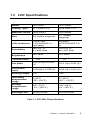
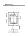
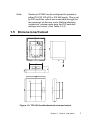
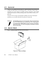
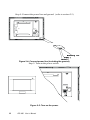
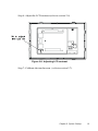
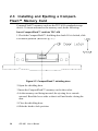
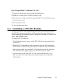
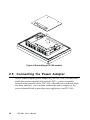
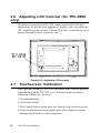
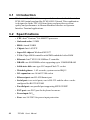
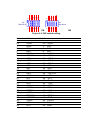
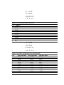
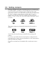
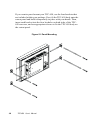
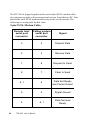
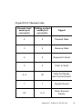
1
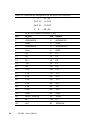
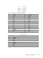
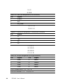
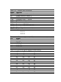
TPC-650
Pentium-based panel PC with
5.7"/6.4" LCD flat panel display
User's Manual
Copyright notice
This document is copyrighted 2000 by Advantech Co., Ltd. All rights
are reserved. Advantech Co., Ltd. reserves the right to make improvements to the products described in this manual at any time without
notice.
No part of this manual may be reproduced, copied, translated or
transmitted in any form or by any means without the prior written
permission of Advantech Co., Ltd. Information provided in this manual
is intended to be accurate and reliable. However, Advantech Co., Ltd.
assumes no responsibility for its use, nor for any infringements upon
the rights of third parties which may result from its use.
Acknowledgments
TPC-650S and TPC-650T are trademarks of Advantech Co., Ltd. IBM,
PC/AT, and PS/2 are trademarks of International Business Machines
Corporation. MS-DOS and Windows CE are trademarks of Microsoft
Corporation. All other brand and product names mentioned herein are
trademarks or registered trademarks of their respective holders.
1st Edition Printed in Taiwan Nov. 2000
Initial Inspection
Before you begin installing your card, please make sure that the
following materials have been shipped:
• TPC-650
• Panel mounting clamper s
• Panel mounting screws
• Keyboard/mouse Y-cable
• Power connector (female)
• Grounding wires
• Copper studs for PC/104 board mounting
• Support CD
• Quick start sheet
• DB-9 null modem cable (optional)
• 32MB CompactFlash™ memory card (optional)
• Windows CE EULA sheet (optional)
• Advantech GeniDAQ Development Edition CD (optional)
• Advantech GeniDAQ Development key (optional)
If any of these items are missing or damaged, contact your distributor
or sales representative immediately.
We have carefully inspected the TPC-650 mechanically and
electrically before shipment. It should be free of marks and scratches
and in perfect working order upon receipt.As you unpack the TPC-650,
check it for signs of shipping damage. (For example, damaged box,
scratches, dents, etc.) If it is damaged or it fails to meet the specifications, notify our service department or your local sales representative
immediately. Also notify the carrier. Retain the shipping carton and
packing material for inspection by the carrier. After inspection, we will
make arrangements to repair or replace the unit.
FCC Class A notes
This equipment has been tested with a Class A computing device and
has been found to comply with Part 15 of FCC Rules. Operation in a
residential area may cause unacceptable interference to radio and TV
receptions, requiring the operator to take whatever steps are necessary
to correct the interference.
Safety Instructions
1.
Read these safety instructions carefully.
2.
Keep this installation reference guide for later reference.
3.
Disconnect this equipment from any AC outlet before cleaning. Do not use
liquid or spray detergents for cleaning. Use a damp cloth.
4.
For pluggable equipment, the power outlet must be installed near the
equipment and must be easily accessible.
5.
Keep this equipment away from humidity.
6.
Put this equipment on a reliable surface during installation. Dropping it or
letting it fall could cause damage.
7.
The openings on the enclosure are for air convection. Protect the equipment from overheating. DO NOT COVER THE OPENINGS.
8.
Make sure the voltage of the power source is correct before connecting the
equipment to the power outlet.
9.
Position the power cord so that people cannot step on it. Do not place
anything over the power cord.
10. All cautions and warnings on the equipment should be noted.
11. If the equipment is not used for a long time, disconnect it from the power
source to avoid damage by transient over-voltage.
12. Never pour any liquid into an opening. This could cause fire or electrical
shock.
13. Never open the equipment. For safety reasons, the equipment should be
opened only by qualified service personnel.
14. If any of the following situations arises, get the equipment checked by
service personnel:
a. The power cord or plug is damaged.
b. Liquid has penetrated into the equipment.
c. The equipment has been exposed to moisture.
d. The equipment does not work well, or you cannot get it to work
according to the installation reference guide.
e. The equipment has been dropped and damaged.
f. The equipment has obvious signs of breakage.
15. DO NOT LEAVE THIS EQUIPMENT IN AN UNCONTROLLED
ENVIRONMENT WHERE THE STORAGE TEMPERATURE IS BELOW 20° C (-4° F) OR ABOVE 60° C (140° F). IT MAY DAMAGE THE
EQUIPMENT.
The sound pressure level at the operator's position according to IEC 704-1:1982
is equal to or less than 70 dB(A).
DISCLAIMER: This set of instructions is given according to IEC 704-1.
Advantech disclaims all responsibility for the accuracy of any statements
contained herein.
Wichtige Sicherheishinweise
1.
Bitte lesen sie Sich diese Hinweise sorgfältig durch.
2.
Heben Sie diese Anleitung für den späteren Gebrauch auf.
3.
Vor jedem Reinigen ist das Gerät vom Stromnetz zu trennen. Verwenden Sie
Keine Flüssig-oder Aerosolreiniger. Am besten dient ein angefeuchtetes Tuch
zur Reinigung.
4.
Die NetzanschluBsteckdose soll nahe dem Gerät angebracht und leicht
zugänglich sein.
5.
Das Gerät ist vor Feuchtigkeit zu schützen.
6.
Bei der Aufstellung des Gerätes ist auf sicheren Stand zu achten. Ein Kippen
oder Fallen könnte Verletzungen hervorrufen.
7.
Die Belüftungsöffnungen dienen zur Luftzirkulation die das Gerät vor
überhitzung schützt. Sorgen Sie dafür, daB diese Öffnungen nicht abgedeckt
werden.
8.
Beachten Sie beim AnschluB an das Stromnetz die AnschluBwerte.
9.
Verlegen Sie die NetzanschluBleitung so, daB niemand darüber fallen kann. Es
sollte auch nichts auf der Leitung abgestellt werden.
10. Alle Hinweise und Warnungen die sich am Geräten befinden sind zu beachten.
11. Wird das Gerät über einen längeren Zeitraum nicht benutzt, sollten Sie es
vom Stromnetz trennen. Somit wird im Falle einer Überspannung eine
Beschädigung vermieden.
12. Durch die Lüftungsöffnungen dürfen niemals Gegenstände oder Flüssigkeiten
in das Gerät gelangen. Dies könnte einen Brand bzw. elektrischen Schlag
auslösen.
13. Öffnen Sie niemals das Gerät. Das Gerät darf aus Gründen der elektrischen
Sicherheit nur von authorisiertem Servicepersonal geöffnet werden.
14. Wenn folgende Situationen auftreten ist das Gerät vom Stromnetz zu trennen
und von einer qualifizierten Servicestelle zu überprüfen:
a. Netzkabel oder Netzstecker sind beschädigt.
b. Flüssigkeit ist in das Gerät eingedrungen.
c. Das Gerät war Feuchtigkeit ausgesetzt.
d. Wenn das Gerät nicht der Bedienungsanleitung entsprechend
funktioniert oder Sie mit Hilfe dieser Anleitung keine Verbesserung
erzielen.
e. Das Gerät ist gefallen und/oder das Gehäuse ist beschädigt.
f. Wenn das Gerät deutliche Anzeichen eines Defektes aufweist.
15. Bitte lassen Sie das Gerät nicht unbehehrt hinten unter -20° C (-4° F) oder
oben 60° C (140° F), weil diesen Temperaturen das Gerät zerstören könten.
Der arbeitsplatzbezogene Schalldruckpegel nach DIN 45 635 Teil 1000 beträgt
70dB(A) oder weiger.
DISCLAIMER: This set of instructions is provided according to IEC704-1.
Advantech disclaims all responsibility for the accuracy of any statements
contained therein.
Contents
CHAPTER 1 General Information ............................. 1
1.1 Introduction .................................................................. 2
1.2 Specifications ............................................................... 2
1.3 LCD Specifications ...................................................... 5
1.4 I/O Arrangement ............................................................. 6
1.5 Dimensions/Cutout ..................................................... 7
CHAPTER 2 System Setup ...................................... 9
2.1 General ......................................................................... 1 0
2.2 Quick Start ................................................................... 1 0
2.3 Installing and Ejecting a CompactFlash™ Memory
Card................................................................................................14
2.4 Installing a PC/104 Module ....................................... 1 5
2.5 Connecting the Power Adapter ................................. 1 6
2.6 Adjusting LCD Contrast (for TPC-650S only) ..... 18
2.7 Touchscreen Calibration .......................................... 18
2.8 First System Boot ..................................................... 19
2.9 Exploded Diagram ..................................................... 20
CHAPTER 3 TPC-650 Kernel: PCM-9450 ................. 2 1
3.1
3.2
3.3
Introduction .................................................................. 22
Specifications ............................................................... 22
PCM-9450 Main Board Specifications .................... 2 3
CHAPTER 4 Networking Communication.............. 3 2
4.1
4.2
4.3
4.4
Introduction .................................................................. 3 3
Networking via LAN................................................... 3 3
Networking via RS-232 ............................................ 3 5
Simple Networking via a Hub.................................. . 3 6
CHAPTER 5 Mounting ................................................3 8
APPENDIX A Programming the Watchdog Timer.... 4 0
A.1
Programming the Watchdog Timer .......................... 41
APPENDIX B Cabling for RS-232 Port ...................... 4 4
Tables
Table
Table
Table
Table
Table
Table
Table
Table
Table
Table
Table
1-1: TPC-650 LCD specifications ........................................................ 5
3-1 Connectors and jumpers ............................................................... 3
3-2: CN1 pin assignment (IDE connector) ........................................... 2 5
3-3: CN2 pin assignment (PC/104 connector) ..................................... 2 6
3-4: CN5/CN6 pin assignment (24-bit/36-bit LCD interface) ............... 2 8
3-5: CN7 pin assignment (LCD inverter power connector) .................. 2 9
3-6: CN13 pin assignment (ATX connector) ....................................... 3 0
3-7:CN16 pin assignment (Touchscreen interface) .......................... 3 0
3-8: JP2 pin assignment (LCD type selector) ..................................... 3 0
3-9: JP3 pin assignment (Clear CMOS switch) .................................. 3 1
3-10: JP5 pin assignment (Standby 5V & Vcc 5V switch) ................... 3 1
Figures
Fig.1-1: I/O arrangement ........................................................................................... 6
Figure 1-2: TPC-650 front/bottom/side view and cutout ......................................... 7
Figure 2-1: Open package ......................................................................................... 1 0
Figure 2-2: Plug in the CompactFlash™ card ........................................................ 1 1
Figure 2-3: Install PC/104 boards .............................................................................. 1 1
Figure 2-4: Connect power line (including the ground) ........................................ 1 2
Figure 2-5: Turn on the power ................................................................................... 1 2
Figure 2-6: Adjusting LCD contrast ......................................................................... 1 3
Figure 2-7: CompactFlash™ shielding door ........................................................... 1 4
Figure 2-8 Installing a PC/104 module ..................................................................... 1 6
Figure 2-9: Connecting the power adapter .............................................................. 1 7
Figure 2-10: Adjusting LCD contrast .................................................................... . 1 8
Figure 2-11: Exploded diagram ................................................................................ . 20
Figure 3-1: PCM-9450 main board ............................................................................ 2 4
CHAPTER
1
General
Information
This chapter gives background
information on the TPC-650.
Sections include:
• Introduction
• Specifications
• LCD Specifications
• I/O Arrangement
• Dimensions/ Cut out
1.1 Introduction
The TPC-650 is a revolutionary product that upgrades the performance
level of small-sized operator interface terminals. It has a high quality
6.4" VGA TFT LCD/5.7" QVGA STN LCD, an Intel® Pentium® 266
MMX™ microprocessor, 10/100 BaseT Ethernet port, two serial ports
(one RS-232, one RS-232/422/485), a CompactFlash™ memory card
slot, an external 16-bit PC/104 expansion slot, and a touchscreen. The
heart of the TPC-650 is a miniature x86 computer that excels in graphic
display and network communication.
The TPC-650 is suitable for various industry applications, including
factory automation, automated production lines, precision machinery,
production process control, environmental control, terminal information system, entertainment management system and so forth. The TPC650 is a reliable, elegant and high performance solution to your
applications.
The TPC-650 is designed as a platform for Windows CE® or other
advanced operating systems. You may choose an optional HMI
software package from Advantech, which is pre-installed on the
CompactFlash™ card. All a user has to do is insert the CompactFlash™ card into the machine, and turn on the power. For more details,
please contact local Advantech distributors or branch offices.
1.2 Specifications
General
• Construction: Plastic molding housing
• Dimensions (W x H x D): 220 x 160 x 57 mm (8.66 x 6.30 x 2.24 inch)
• Cutout: 159 x 115 mm (6.26 x 4.53 inch)
• Weight: 1.7 kg (3.7 lb)
Standard functions
• CPU: Intel® Pentium® 266 MMX™
2
TPC-650 User's Manual
• Core logic: Intel ®430TX chipset
• BIOS: Award 256 KB flash memory
• RAM: 32MB SO-DIMM SDRAM
• IDE device interface: Supports one CompactFlash™ memory card
• Parallel port: Supports SPP/EPP/ECP; D-SUB 25-pin connector
• Serial ports: One RS-232 port and one RS-232/422/485 port.
(DIP switches configure these serial ports; please refer to Table 3-13
• PS/2 keyboard/mouse connector: 6-pin mini-DIN keyboard
connector
• Watchdog timer: programmable timer with time intervals 1~62
seconds
• External expansion slot: 104-pin connector, supports up to two
cascaded 16-bit PC/104 cards
• Battery: 3V @ 195mA Lithium battery for CMOS backup
Ethernet interface
• Chipset: Intel® 82559 10/100 Base-T controller
• Network (LAN): Novell NE1000/2000 compatible. Supports both
boot ROM function and software drivers
VGA display interface
• Chipset: C&T 69000
• Display memory: 2MB SDRAM embedded
• Hardware Windows acceleration: 32-bit graphic engine
• Resolution/color depth: 640x480 @ 256k colors
Power rating
• Input voltage: nominal 24VDC(18~30V)
• Input current: max. 2.2 Amp.
• Power consumption: 27 Watts (5V @ 3A, 12V @ 1A)
Chapter 1 General Information
3
Environmental specifications
• Operating temperature: 0~45°C (32°~113°F)
• Humidity: 0~95% RH (non-condensing). 40°C
• Safety: UL/CSA certificated
• FCC Class A and CE certificated
• Vibration: 10~18 Hz, 1.5mm peak-to-peak displacement
18~500 Hz, 1G acceleration
Touchscreen
• Type: resistive
• Resolution: 1024 x 1024
• Light transmission: 68%
• Lifetime: 1 million touches, minimum
4
TPC-650 User's Manual
1.3 LCD Specifications
Model
TPC -650T
TPC -650S
D isplay Type
TFT color LC D
STN color LC D
Maximal colors
256k colors
256 colors
Siz e
6.4 i nches di agonal
5.7 i nches
di agonal
LC D model no.
Pri meVi ew
V 16C 6448A C or
equi valent
Kyocera
KC S3224ASTT-X6
R esolution
640 x R, G,
B x 480 dots
320 x R, G,
B x 240 dots
300 cd/m2
110 cd/m2
120
25
B rightness
C ontrast ratio
D ot pitch
0.0675 (H) x 0.203
(V)
0.12 (H) x 0.36 (V)
Pixel pitch
(mm)
0.203(H) x 0.203(V)
0.34 (H) x 0.34 (V)
View ing angle
110°
100°
Operating
temperature
range
0~55°C
(32°~132°F)
0°~50°C
(32°~ 122°F)
Storage
temperature
range
-25°~70°C
(-10°~158°F)
-20°~60°C
(-4°~140°F)
B acklight life
20,000 hours
10,000 hours
Table 1-1: TPC-650 LCD specifications
Chapter 1 General Information
5
1.4 I/O Arrangement
The I/O arrangement of the TPC-650 is as shown below:
Fig.1-1: I/O arrangement
6
TPC-650 User's Manual
Note:
Serial port COM2 can be configured to operate in
either RS-232, RS-422 or RS-485 mode. This is set
by DIP switches, which are accessible through the
two openings on the rear cover. Before attaching
connectors, please make sure the DIP switches
settings are correct. (See Table 3.4-3)
1.5 Dimensions/Cutout
Figure 1-2: TPC-650 front/bottom/side view and cutout
Chapter 1 General Information
7
8
TPC-650 User's Manual
CHAPTER
2
System Setup
This chapter explains how to set up the
TPC-650 hardware.
Sections include:
• General
• Quick Start
• Installing a CompactFlash™ Memory
card
• Installing a PC/104 Module
• Connecting the Power Adapter
• LCD Contrast (for TPC-650S only)
• Touch Screen Calibration
• First System Boot
• Exploded Diagam
2.1 General
The TPC-650 compact profile panel PC can simultaneously monitor and
sample the data from several traditional PLC controllers. It takes full
advantage of a wide range of available software programs, and its high
display performance and networking make it best choice in this era of
the web.
The TPC-650 is easily customizable to fulfill your needs. The kernel
modules are accessible when the front bezel is removed.
Warning!
Verify that power source has been disconnected from
the TPC-650 before you install any of its components
or accessories. Note that no power source should be
attached to the TPC-650 during any hardware installation or servicing.
2.2 Quick Start
Step 1: Open package and show all accessories.
Figure 2-1: Open package
10
tPC-650 User's Manual
Step 2: Plug in the CompactFlash™ card (refer to section 2.3).
Figure 2-2: Plug in the CompactFlash™ card
Step 3: Install the PC/104 boards (refer to section 2.4)
Figure 2-3: Install PC/104 boards
Chapter 2 System Startup
11
Step 4: Connect the power line and ground. (refer to section 2.5)
Figure 2-4: Connect power line (including the ground)
Step 5: Turn on the power switch
Figure 2-5: Turn on the power
12
tPC-650 User's Manual
Step 6: Adjust the LCD contrast (refer to section 2.6)
Figure 2-6: Adjusting LCD contrast
Step 7: Calibrate the touchscreen. (refer to section 2.7).
Chapter 2 System Startup
13
2.3 Installing and Ejecting a CompactFlash™ Memory Card
CompactFlash™ memory cards are the TPC-650's standard storage
device. To insert and remove the memory card, do the following:
Insert CompactFlash™ card into TPC-650
1.Check the CompactFlash™ shielding door latch. If it is locked, slide
it to unlock position. (Refer to Fig. 2-7)
Figure 2-7: CompactFlash™ shielding door
2.Open the shielding door.
3.Insert the CompactFlash™ memory card to the socket.
4.As the memory card being inserted, the ejecting lever extrude
outward. Bend the lever aside so that it will not hinder closing the
door.
5.Close the shielding door.
6.Slide the latch to lock position.
14
tPC-650 User's Manual
Eject CompactFlash™ card from TPC-650
1.Unlock the door latch and open the shielding door.
2.Bend the ejecting lever so that it points to you.
3.Push the lever inside, and the CompactFlash™ card will loosen and
be ejected outward.
4.Take away the card.
5.Close and lock the door.
2.4 Installing a PC/104 Module
The TPC-650's PC/104 connector gives you the flexibility to attach to
the PC/104 expansion modules, which perform the same functions as
traditional plug-in expansion cards. Using these modules will save you
space and valuable slots.
To install a PC/104 module:
1.Verify that the power source to the TPC-650 has been properly disconnected.
2.Plug the PC/104 module's male connectors into the ISA expansion
slot's female connectors by pressing the module firmly with caution.
3.If necessary, stack the second PC/104 add-on card on the first one.
The TPC-650 can support up to two PC/104 cards cascaded.
4.Advantech provides optional PC/104 expansion kits that cover
add-on cards. You can contact local representatives for detailed
information.
Chapter 2 System Startup
15
Figure 2-8 Installing a PC/104 module
2.5 Connecting the Power Adapter
Before connecting the power adapter to your TPC-650, you must first
attach the power terminal block onto the 24VDC power receptable
located on the rear side of the TPC-650. After the power terminal block
has been attached, you can then connect the power adapter to the
power terminal block to provide power supplies to your TPC-650.
16
tPC-650 User's Manual
To connect the power adapter:
1.Identify each wire of the power adapter cord (you must first make
sure which is +, - or GND specifically).
2.Unscrew the screws on the power terminal. insert each wire of the
power adapter cord specifically into its designated connector hole
(+, - and GND) on the power terminal block. Fasten the screws to
secure wires in the connector holes.
Figure 2-9: Connecting the power adapter
Note:
The power terminal block is in the accessory pack
shipped together with the TPC-650. However, the
24VDC power adapter is an optional item to TPC-650.
You can purchase it from Advantech separately, or
find it from another vendor.
Warning:
Avoiding shorting any bare wires since it may cause
damages to your system or device.
Chapter 2 System Startup
17
2.6 Adjusting LCD Contrast (for TPC-650S
only)
The default setting of the STN LCD contrast may not fit individual
applications. To get the most appropriate display, users can adjust the
VR (variable resistor) on the I/O board. This VR is accessible by screw
drivers through the hole on the rear case.
Figure 2-10: Adjusting LCD contrast
2.7 Touchscreen Calibration
If the optional Windows CE® OS or Advantech HMI software package
is purchased with the TPC-650, you will find a touchscreen driver
which can calibrate its sensitivity:
1. Click Start/Settings
2. Click Control Panel
3. The Control Panel window pops out. Double click touchscreen icon.
4. Press the touchscreen at the radial button with a finger or another
pointing tool harmless to the touchscreen.
18
tPC-650 User's Manual
5: Press the touchscreen where the 2nd radial button appears.
6: Close the calibration program. The calibration is complete.
2.8 First System Boot
After you have properly installed the CompactFlash™ memory card
pre-installed with Windows CE® or with specific application software,
all you have to do is simply plug in the power and the system is ready
for the first boot.
Please follow the steps below to perform your first system boot:
1.Turn on the power switch. Meanwhile, the power LED on the front
panel will light up.
2.The Windows CE® operating system starts to boot from the Compact
Flash™ memory.
3.Wait for a while for Windows CE® to complete its first startup.
After you have successfully booted for the first time, you can now
assign a device name to your TPC-650 for network identification.
1.First click on Start/Settings/Control Panel/Communication Proper
ties to access the Communication Properties page.
2.Select the Device Name tab on the properties page, and assign a
device name to your TPC-650. The Device Name is what comes to
distinguish your TPC-650 within the network environment.
3.Click on OK to accept the Device Name setting.
4.Click on Start/Run.
5.When the dialogue box pops up, key in "regsave" command in the
text box and click OK.
6.Reboot your system to make your Device Name effective on the
network.
After you have assigned a Device Name to your TPC-650 on the
network, you can proceed further with other configurations or installation procedures.
Chapter 2 System Startup
19
Warning: Be sure to execute "regsave" command after making a
change on any system parameters. Otherwise all
parameters will restore to default after system reboot.
2.9 Exploded Diagram
The following exploded diagram is provided to help with assembly or
disassembly of the TPC-650.
Figure 2-11: Exploded diagram
20
tPC-650 User's Manual
CHAPTER
3
TPC-650 Kernel:
PCM-9450
The heart of the TPC-650 is
composed of two boards:the
Advantech PCM-9450 main board
and the PCM-9450 I/O board. The
specifications for both are in this
chapter.
3.1 Introduction
The heart of the TPC-650 is composed of two boards: the Advantech
PCM-9450 main board and the PCM-9450 I/O board. This combination
is designed to fit the TPC-650 form factor, and provides excellent
quality and performance in Human Machine Interface or Operator
Interface Terminal applications.
3.2 Specifications
• CPU: Intel® Pentium® 266 MMX™ processor
• On-board cache: 512 KB
• BIOS: Award 256KB
• Chipset: Intel ® 430TX
• Super I/O chipset: Winbond W83977
• VGA: Chips 69000 controller with 2MB embedded video RAM
• Ethernet: Intel® 82559 10/100Base-T controller
• DRAM: one SO-DIMM socket supporting up to 128MB SDRAM
• Solid-state disk: one type-II CompactFlash ™ socket
• Watchdog timer: 1~62 seconds; system reset or IRQ15
• I/O expansion: one 16-bit PC/104 socket
• Ethernet port: one RJ-45 Ethernet port
• Serial port: two serial ports; one is RS-232 and the other can be
configured for RS-232/422/485
• Parallel port: one parallel port supporting SPP/ECP/EPP
• PS/2 port: one PS/2 port for keyboard or mouse
• Power input: 24VDC
• Fuse: one 5A/250V for power input protection
22
TPC-650 User's Manual
3.3 PCM-9450 Main Board Specifications
Table 3-1 Connectors and jumpers
Name
Function
CN1
IDE connector
CN2
PC/104 connector
CN5
24-bit LCD interface
CN6
36-bit LCD interface
CN7
LCD inverter power connector
CN13
ATX connector
CN16
Touchscreen interface
JP2
LCD type selector
JP3
Clear CMOS switch
JP5
Standby 5V, VCC 5V switch
Chapter 3 TPC-650 Kernel
23
Figure 3-1: PCM-9450 main board
24
TPC-650 User's Manual
Table 3-2: CN1 pin assignment (IDE connector)
Pin
Signal
Pin
Signal
1
IDECS01#
2
DDP0
3
IDECS03#
4
DDP1
5
DAP0
6
DDP2
7
DAP1
8
DDP3
9
DAP2
10
DDP4
11
IDEACK0#
12
DDP5
13
IRQ1
14
DDP6
15
IRQ8
16
DDP7
17
KBRESET#
18
DDP8
19
A20GATE
20
DDP9
21
24MHZ
22
DDP10
23
PS_ON#
24
DDP11
25
5VSB
26
DDP12
27
GND
28
DDP13
29
IDERSTP#
30
DDP14
31
PIIX_RI#
32
DDP15
33
IDEIORDY0
34
IDEIOR0#
35
IDEDRQ0
36
IDEIOW0#
37
IDELED0
38
IDEIRQ0#
39
GND
40
YU
41
ENVEE
42
YD
43
N/C
44
XR
45
TDP1
46
XL
47
TDN1
48
RDP1
49
GND
50
RDN1
51
VEEO_2
52
GND
Chapter 3 TPC-650 Kernel
25
Table 3-3: CN2 pin assignment (PC/104 connector)
Number Row A
26
Row B
GND
Row C
Row D
GND
GND
1
IOCHCHK#
2
SD7
RESETDRV
SBHE#
3
SD6
+5 V
LA23
IOCS16#
4
SD5
IRQ9
LA22
IRQ10
5
SD4
-5 V
LA21
IRQ11
6
SD3
DRQ2
LA20
IRQ12
7
SD2
-12 V
LA19
IRQ15
8
SD1
ENDXFR#
LA18
IRQ14
9
SD0
+12 V
LA17
DACK0#
10
IOCHRDY N/C
MEMR#
DRQ0
11
AEN
MEMW#
DACK5#
12
SA19
SMEMR#
SD8
DRQ5
13
SA18
IOW#
SD9
DACK6#
14
SA17
IOR#
SD10
DRQ6
15
SA16
DACK3#
SD11
DACK7#
16
SA15
DRQ3
SD12
DRQ7
17
SA14
DACK1#
SD13
+5 V
18
SA13
DRQ1
SD14
MASTER#
19
SA12
REFRESH# SD15
GND
20
SA11
SYSCLK
N/C
GND
21
SA10
IRQ7
—
—
22
SA9
IRQ6
—
—
23
SA8
IRQ5
—
—
SMEMW#
TPC-650 User's Manual
MEMCS16#
24
SA7
IRQ4
—
—
25
SA6
IRQ3
—
—
26
SA5
DACK2#
—
—
27
SA4
TC
—
—-
28
SA3
BALE
—
—
29
SA2
+5 V
—
—
26
SA1
OSC
—
—
31
SA0
GND
—
—
32
GND
GND
—
—
# low active
Chapter 3 TPC-650 Kernel
27
Table 3-4: CN5/CN6 pin assignment (24-bit/36-bit LCD interface)
1 3....
37 39
O O O......O O O
O O O......O O O
2
4.......38 40
24-bit LCD display connector (CN5)
Pin
Signal
Pin
Signal
1
VDDSAFE5
2
VDDSAFE5
3
GND
4
GND
5
VDDSAFE3
6
VDDSAFE3
7
Vcon
8
GND
9
P0
10
P1
11
P2
12
P3
13
P4
14
P5
16
P7
15
28
P6
17
P8
18
P9
19
P10
20
P11
21
P12
22
P13
23
P14
24
P15
25
P16
26
P17
27
P18
28
P19
29
P20
30
P21
31
P22
32
P23
33
GND
34
GND
35
SHIFT CLOCK
36
FILM
37
M
38
LP
39
N/C
40
ENAVEE
TPC-650 User's Manual
1 3....
17 19
O O O......O O O
O O O......O O O
2
4.......18 20
36-bit LCD display connector (CN6)
Pin
Signal
Pin
Signal
1
GND
2
GND
3
P24
4
P25
5
P26
6
P27
7
P28
8
P29
9
P30
10
P31
11
P32
12
P33
13
P34
14
P35
15
GND
16
GND
17
ENABKL
18
N/C
19
N/C
20
N/C
12 3 4 5
OOO OO
Table 3-5: CN7 pin assignment (LCD inverter power connector)
Pin
Signal
1
+12 V
2
GND
3
ENABKL
4
VBR
5
+5 V
Chapter 3 TPC-650 Kernel
29
12 3
OOO
Table 3-6: CN13 pin assignment (ATX connector)
Pin
Signal
1
STB5V
2
N/C
3
PS_ON#
12 3 4
OOO O
Table 3-7: CN16 pin assignment (Touchscreen interface)
Pin
Signal
1
XL
2
XR
3
YD
4
YU
1 3 5 7
OOOO
OOOO
2 4 6 8
Table 3-8: JP2 pin assignment (LCD type selector)
Pin
Signal
Pin
Signal
1
GND
2
MMA3
3
GND
4
MMA4
5
GND
6
MMA5
7
GND
8
MMA6
FOR PRIMEVIEW 6.4" 3-4,7-8
FOR KYOCERA 5.7" 1-2,5-6,7-8
30
TPC-650 User's Manual
12 3
OOO
Table 3-9: JP3 pin assignment (Clear CMOS switch)
Pin
Signal
1
VBAT3V_IN
2
VBAT3V
3
GND
1-2:
NORMAL
2-3:
CLEAR CMOS
12 3
OOO
Table 3-10: JP5 pin assignment (Standby 5V & Vcc 5V switch)
Pin
Signal
1
STB5V
2
STB5V_VCC
3
VCC
1-2:
STANT BY 5V
2-3:
VCC 5V
Chapter 3 TPC-650 Kernel
31
3.4 PCM-9450 I/O Board Specifications
Figure 3-1: PCM-9450 I/O board
Table 3-11: Jumpers and connectors
Name
JP1
S1
S2
CN2
CN7
CN8
CN9
CN10
RJ-45
PS/2
Function
LCD power switch connector
COM2 selector switch 1
COM2 selector switch 2
CompactFlash™ socket
DB-25 Parallel port
Power connector
Serial port RS-232
Serial port RS-232/422/485
Ethernet port
Keyboard/mouse connector
12 3
OOO
Table 3-12: JP1 pin assignment (LCD power switch connector)
Pin
1
2
3
1-2 :
2-3 :
Signal
1.5V
ENVEE
VEEO_3
KYO 6.0"
KYO 5.7"
Table 3-13: S1/S2 DIP switch setting (COM2 setting)
1
2
3
4
5
6
1
2
3
4
5
6
485
off
off
off
off
on
on
on
on
off
on
off
X
422
off
off
off
off
on
on
on
on
off
off
on
X
232
on
on
on
on
off
off
off
off
on
off
off
X
S1
S1
S1
S1
S1
S1
S2
S2
S2
S2
S2
S2
7
8
9
10
11
12
7
8
9
10
11
12
S1
SW DIP-6
S2
1
2
3
4
5
6
1
2
3
4
5
6
SW DIP-6
ON
ON
Figure 3-2: DIP switch setting
Table 3-14: CN2 (CompactFlash™ socket)
Pin
1
3
5
7
9
11
13
15
17
19
21
23
25
27
29
31
33
35
37
39
41
43
45
47
49
Signal
-
GND
D04
D06
CS0#
ATA SEL
A08
VCC
A05
A03
A01
D00
D02
-CD2
D11
D13
D15
-VS1
-IOWR
INTRQ
-CSEL
-RESER
-INPACK
-DASP
D08
D10
Pin
2
4
6
8
10
12
14
16
18
20
22
24
26
28
30
32
34
36
38
40
42
44
46
48
50
Signal
D03
D05
D07
A10 2
A09 2
A07 2
A06 2
A04 2
A02
A00
D01
-IOCS16
-CD1
D12
D141
-CS1
-IORD
-WE
V CC
-VS2
IORDY
-REG
-PDIAG
D09
GND
13 12
2 1
O O O O .........O O O
OO
........... O O O
25
14 15
Table 3-15: CN7 (Parallel port)
Pin
1
2
3
4
5
6
7
8
9
10
11
12
13
Signal
STROBE#
D0
D1
D2
D3
D4
D5
D6
D7
ACK#
BUSY
PE
SLCT
Pin
14
15
16
17
18
19
20
21
22
23
24
25
26
Table 3-16: CN8 (Power connector)
Pin
1
2
3
4
5
GND
RTN
+24V
SW1
SW2
Signal
AUTOFD#
ERR
INIT#
SLCTINI#
GND
GND
GND
GND
GND
GND
GND
GND
N/C
6 7 8 9
OOOO
OOOOO
12 3 4 5
Table 3-17: CN9 (Serial port RS-232)
Pin
1
2
3
4
5
6
7
8
9
Signal
DCD
RXD
TXD
DTR
GND
DSR
RTS
CTS
RI
6 7 8 9
OOOO
OOOOO
12 3 4 5
Table 3-18: CN10 (Serial port RS-232/422/485)
Pin
1
2
3
4
5
6
7
8
9
10
RS-232 port
DCD
DSR
RxD
RTS
TxD
CTS
DTR
RI
GND
N/C
RS-422 port
TXDN/C
TXD+
N/C
RXD+
N/C
RXDN/C
GND
N/C
RS-485 port
DATAN/C
DATA+
N/C
N/C
N/C
N/C
N/C
GND
N/C
OOOOOO O O
1 2 3 4 5 6 7 8
Table 3-19: RJ-45 (Ethernet port)
Pin
1
2
3
4
5
6
7
8
Signal
TX+
TXRX+
N/C
N/C
RXN/C
N/C
6O
4O
2O
•
O5
O3
O1
Table 3-20: PS/2 (Keyboard/mouse connector)
Pin
1
2
3
4
5
6
Signal
KB DATA
MS DATA
GND
V CC
KB CLOCK
MS CLOCK
3.5 Safety Precautions
Warning!
Always completely disconnect the power cord from
your chassis whenever you are working on it. Do not
make connections while the power is on, because
sensitive electronic components can be damaged by
the sudden rush of power. Only experienced electronics personnel should open the PC chassis.
Caution!
Always ground yourself to remove any static charge
before touching the CPU card. Modern electronic
devices are very sensitive to static electric charges.
Use a grounding wrist strap at all times. Place all
electronic components on a static-dissipative surface
or in a static-shielded bag when they are not in the
chassis.
3.6 Setting Jumpers
You may configure your card to match the needs of your application
by setting jumpers. A jumper is a metal bridge that closes an electrical
circuit. It consists of two metal pins and a small metal clip (often
protected by a plastic cover) that slides over the pins to connect them.
To "close" a jumper, connect the pins with the clip. To "open” a
jumper, remove the clip. Sometimes a jumper will have three pins,
labeled 1, 2 and 3. In this case, you would connect either pins 1 and 2,
or 2 and 3.
1
Open
Closed
2
3
Closed 2 - 3
The jumper settings are schematically depicted in this manual as
follows:
1
Open
Closed
Closed 2 - 3
A pair of needle-nose pliers may be helpful when working with
jumpers.
If you have any doubts about the best hardware configuration for
your application, contact your local distributor or sales representative
before you make any changes.
Generally, you simply need a standard cable to make most connections.
CHAPTER
4
Networking
Communication
This chapter describes the ways to
get your TPC-650 connected to the
host PC.
Sections include:
• Introduction
• Networking via LAN
• Networking via RS-232
• Simple Networking via a Hub
4.1 Introduction
The TPC-650 is designed as a networking device that readily connects
to a host PC either via an existing LAN or an RS-232 interface. Its
network capability makes it nothing less than a powerful platform for
any application that demands networking communication or remote file
transfer. The following sections will guide you through the networking
steps for the TPC-650.
4.2 Networking via LAN
Ethernet has been so predominant in LANs that we have come to
regard it as the de facto standard for network communication within
LANs. The TPC-650 takes advantage of Ethernet networking to
connect to a host PC for convenient network communication and file
transfer.
Please follow the procedure described below to set up network
connection between the TPC-650 and a host PC via an Ethernet
network:
1. Before connecting to a LAN, make sure you have properly set up
your host PC on an Ethernet LAN running TCP/IP networking
protocol. If you have not installed the TCP/IP network protocol on
your host PC, you must install it first before joining the host PC to
the Ethernet LAN.
2. Make sure your TPC-650 is running an OS that has its TCP/IP
network protocol enabled.
Note:
If you use a CompactFlash™ drive which is preinstalled with Windows CE or other network-enabling
software, your TPC-650 is ready for TCP/IP networking. You do not have to install other components to
run TCP/IP networking.
3. Disconnect any power source from your TPC-650.
Note:
33
Be sure to power off the TPC-650 before you connect
or disconnect any cable.
TPC-650 User's Manual
4. Use a twisted-pair UTP or STP cable (category 3, 4, 5) to connect
the TPC-650 through its RJ-45 port to a hub (or a switch) within the
Ethernet LAN to which your host PC is also connected.
5. Assign valid IP addresses for your TPC-650 and host PC. If you are
joining an existing Intranet, ask your network administrator for
valid IP addresses. If you are using a DHCP server on the network,
you need not assign IP addresses yourself.
Note:
To assign IP addresses to your computers, just
access the Start/Settings/Control Panel/Network
menu, and enter valid IP addresses for each computer.
Note:
If your network is using a DHCP server for dynamic
IP address assignment, you need not assign new
addresses yourself. The IP addresses will be automatically assigned to each networking device once it
is connected to the network.
6. Enter the device name for your TPC-650 for network identification.
Note:
To assign a device name to your TPC-650, just
access the Start/Settings/Control Panel/Network
menu, and enter the device name for your TPC-650.
You have to reboot your system to make the device
name viable on the network.
7. After properly establishing the IP status and the device name of
your machine on the network, you must reboot to make the settings
viable on the network.
8. After rebooting is complete, verify that your TPC-650 is functioning within the network.
Chapter 4 Networking Communication
34
Note:
To verify that your TPC-650 has joined the network
and is properly connected with your host PC, just try
to access your host PC through the Windows CE
Explorer by typing //host_name_of_host_PC in the
address bar. Press Enter to search for the host PC.
If the connection is successful, you can see the
network shares that are available from the host PC.
Or you can simply "ping" your TPC-650 from your
host PC to make sure TCP/IP is working. (e.g.
c:\ping IP_address_of_your_TPC-650 or device_name_of
_your_TPC-650 )
4.3 Networking via RS-232
RS-232 is a time-honored standard interface for industrial automation.
It is very convenient to implement, albeit much more limited in its
communication distance. The TPC-650 is provided with a RS-232 port,
from which it can be connected to your host PC via a NULL modem
cable.
Please follow the procedures described below to set up network
connection between the TPC-650 and a host PC via an RS-232
interface:
1. Before connecting to RS-232, first make sure your COM port
service on the host PC has been enabled.
Note:
If you are running Windows 95/98 on the host PC, the
COM port service should be enabled on default
without extra installation of other components. On the
other hand, if you are running Windows NT on the
host PC, make sure the RAS (i.e. Remote Access
Service) on your host PC system is running properly.
If you have not installed the RAS, you must install it
on your system.
2. Use the DB-9 NULL modem cable (that accompanies your TPC-650)
to connect the TPC-650 through its RS-232 port to the COM port of
your host PC.
35
TPC-650 User's Manual
Note:
Be sure to power off the HMI-640S before you
connect or disconnect any cable.
3. Power up your TPC-650. After the system boot has been completed, try accessing the Start/Programs/Communication/Remote
Networking menu.
4. Click Make New Connection to pop up a dialog box, and choose
Direct Connection.
5. Double-click the New Connection icon to connect to the PC.
6. After you have successfully connected to the host PC, just verify
the validity of your RS-232 connection by typing the host name of
your host PC in the Address Bar of your Windows CE Explorer.
Press Enter to search for the host PC. If the connection has been
successful, you will see the network shares that are available from
the host PC.
4.4 Simple Networking via a Hub
If you want to connect your TPC-650 and the host PC only through
RJ-45 ports, you must use twisted-pair cables to connect both to a
central hub. Note that this network configuration is essentially the
same as Ethernet, despite a configuration of merely two end nodes.
After you have established a proper connection, you can verify the
network communication by following the procedure described above.
Chapter 4 Networking Communication
36
37
TPC-650 User's Manual
CHAPTER
5
Mounting
This chapter describes
the ways to mount
your TPC-650.
If you want to panel mount your TPC-650, use the four brackets that
are included within your package. First, fit the TPC-650 body onto the
cutout panel and hold it temporarily in place with your hands. Then,
insert each bracket into the four keyholes on both sides of the TPC650 rear case, and use appropriate screws to fix the TPC-650 body on
the cutout panel.
Figure 5-1 Panel Mounting
39
TPC-650 User's Manual
APPENDIX
A
Programming the
Watchdog Timer
The TPC-650 is equipped with a
watchdog timer that resets the CPU
or generates an interrupt if processing comes to a standstill for any
reason. This feature ensures system
reliability in industrial standalone or
unmanned environments.
A.1
Programming the Watchdog Timer
To program the watchdog timer, you must write a program which writes
I/O port address 443 (hex). The output data is a time interval value. The
value range is from 01 (hex) to 3F (hex), and the related time interval is 1
sec. to 63 sec.
41
Data
Time Interval
01
1 sec.
02
2 sec.
03
3 sec.
04
4 sec.
•
•
•
•
•
•
3F
63 sec.
TPC-650 User's Manual
After data entry, your program must refresh the watchdog timer by
rewriting I/O port 443 (hex) while simultaneously setting it. When you
want to disable the watchdog timer, your program should read I/O port
443 (hex).
The following example shows how you might program the watchdog
timer in BASIC:
10
20
30
40
50
60
70
80
REM Watchdog timer example program
OUT &H443, data REM Start and restart the watchdog
GOSUB 1000 REM Your application task #1,
OUT &H443, data REM Reset the timer
GOSUB 2000 REM Your application task #2,
OUT &H443, data REM Reset the timer
X=INP (&H443) REM Disable the watchdog timer
END
1000
•
•
•
1070
2000
•
•
•
2090
REM Subroutine #1, your application task
•
•
•
RETURN
REM Subroutine #2, your application task
•
•
•
RETURN
Appendix A Watchdog Timer
42
43
TPC-650 User's Manual
APPENDIX
B
Cabling for RS232 Port
The TPC-650 is equipped with a
watchdog timer that resets the
CPU if processing comes to a
standstill for any reason. This
feature ensures system reliability
in industrial standalone or
unmanned environments.
The TPC-650 is shipped together with a serial cable (NULL modem cable)
for customers to make a direct connection between it and the host PC. Note
that off-the-shelf NULL modem cables may not be wired correctly. The
following is a wiring table for this cable:
9-pin NULL Modem Cable:
45
Remote host
serial port
connector
Calling system
serial port
connector
Signal
3
2
Transmit Data
2
3
Receive Data
7
8
Request to Send
8
7
Clear to Send
6, 1
4
Data Set Ready
and Carrier Detect
5
5
Signal Ground
4
6, 1
Data Terminal
Ready
TPC-650 User's Manual
25-pin NULL Modem Cable:
Remote host
serial port
connector
Calling system
serial port
connector
Signal
2
3
Transmit Data
3
2
Receive Data
4
5
Request to Send
5
4
Clear to Send
6, 8
20
Data Set Ready
and Carrier Detect
7
7
Signal Ground
20
6, 8
Data Terminal
Ready
Appendix B Cabling for RS-232 Port
46