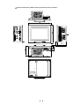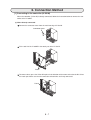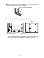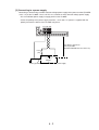
1
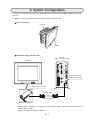
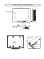
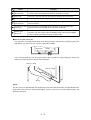
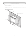
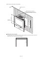
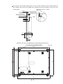
Version 1.0
Produced in Jan. 2004
Instruction Manual
LCD monitor
IV-08MP
Thank you for purchasing the SHARP IV-08MP LCD
monitor. Read this introductory instruction manual
carefully to thoroughly familiarize yourself with the
functions and proper procedures for operation.
Notes
• This manual was written with the utmost care. However, if you have any question or
inquiries concerning the product, please feel free to contact our dealers or service agents.
• Copying all or part of this booklet is prohibited.
• The contents of this manual may be revised or modified for improvement without prior
notice.
TOP - 1
Components of IV-08MP
The components of IV-08MP are as follows.
Accessories
One(1) LCD monitor IV-08MP
• Four (4) Main housing angle brackets
• Two (2) Controller angle brackets
• Two (2) Securing screws
• One (1) Stylus pen
• One (1) Instruction manual
Components - 1
Safety Precautions
Read this instruction manual and the attached documents carefully before installing, operating, or performing any maintenance, in order to keep the machine working correctly. Make sure you understand all of
the equipment details, safety information, and cautions before using this machine. In this user's manual,
the safety precautions are categorized as "Caution".
Caution : Improper handling may cause dangerous situation, moderate or light injury, or damage to
equipment.
Even when
Caution is given, serious results may occur depending on the circumstances. Be sure to follow
the advice given.
The following symbols are used to prohibit action.
: This means do not do what is described. For example, prohibited disassembly is shown as
(1) Installation
Caution
• Use only in the environments specified in the catalog and instruction manual.
Electric shock, fire or malfunction may result if used in the environment with high temperature,
high humidity, dust, corrosive gas, excessive vibration or impact.
• Install the equipment only as described in the manual.
An improper installation may cause the equipment to fall off, breakdown, or malfunction.
• Never leave debris from wire cutting or any other foreign matter in the equipment.
It may cause a fire, breakdown or malfunction.
(2) Wiring
Caution
• Connect only to the specified power source.
Connection to the wrong power source may cause a fire.
• Wiring should be performed by a qualified electrician.
Improper wiring may lead to a fire, machine failure or electric shock.
(3) Maintenance
Prohibit
• Do not disassemble or modify the camera.
It may cause a fire, breakdown, or malfunction.
Sefety - 1
.
1. Outline/ Features
This touch panel type 8.4-inch TFT color LCD monitor , the IV-08MP, realizes power saving, automation and
cost saving in inspection/measurement processes as the monitor for image sensor in various arenas. Using
LCD with high-brightness and wide viewing angle, this monitor which is thinner and smaller than CRT can be
easily mounted to the equipment. The touch panel provides a function to enter various settings to the controller (IV-S51M) by simply touching the screen. Also, since the IV-S51M can be connected directly to the
backside of the IV-08MP to be used as one unit, the space required to install the unit will be smaller.
Features
Thin and light weight. Direct connection to the IV-S51M.
The low-profile monitor with approx.46mm in depth is designed to provide easy installation to the
equipment or the wall panel. Since the IV-S51M can be connected directly to the backside of the IV08MP to be used as one unit, the space which would be required for wiring cables to the controller
will be saved.
High-brightness and wide viewing angle for better viewing experience. TFT color LCD.
Using the high-brightness (more than 400cd/m2) TFT color LCD, this monitor can be used in the
bright
environment. The wide viewing angle provides the wider range with up/down: 40°/60°, and left/right:
65°.
IV-S51M settings can be entered from the touch panel.
By simply touching the screen, measurement program or setting of various parameters for the image
sensor camera, IV-S51M, can be easily entered.
1-1
2. Precautions for Use
Pay attention to the points below when handling the IV-08MP.
(1) Installed location and environment
• Use the equipment in the environment where the ambient temperature is 0~40°C and the relative
humidity is less than 90% RH. If the ambient temperature is out of the above range, install a forced
fan or an air conditioner to keep the temperature within the required range.
• When this equipment and the controller (IV-S51M) are directly connected and used as one unit,
make sure that the ambient temperature at this equipment side is within 0 to 40°C.
• Avoid installing this equipment in the place where the temperature would change drastically causing
condensation.
• Avoid installing this equipment in the place where it would be exposed to the direct sunlight.
• Do not install this equipment in the place where excessive vibration or impact would directly affect
the equipment.
• Avoid installing this equipment in the place where it would be exposed to water, corrosive gasses,
combustible gasses, solutions, or grinding oil. Do not install the equipment in the place with too
much dust, salt, or iron.
(2) Mounting
• Provide enough space for ventilation. If the ventilation is blocked, the internal temperature of the
equipment may rise resulting in a fire.
• Avoid mounting this equipment onto the panel where high-tension equipment is installed. Keep this
equipment away from high-tension cable or electric motor cable by at least 200mm when the equipment is mounted.
(3) Use
• Do not use the power supply of this equipment to power other equipment. Do not use any power
supply other than 24V DC.
• Discontinue the use of this equipment promptly when any abnormality (over heat, odor, smoke, etc.)
or failure is observed, and contact our dealers or service agents.
• Do not drop or give a strong impact to this equipment. It may damage the glass of display part.
• In dry environment, a human body may charge excessive static electricity. Static electricity may
cause a damage to the components built inside of this equipment (base plate). Discharge the
electricity first by touching the grounded metal before touching this equipment.
(4) Maintenance
• Except for a service representative, do not take off the back cover or the mounting frame of this
equipment.
Touching high-voltage parts inside of the equipment may cause electric shock or machine failure.
• Clean this equipment with soft dry cloth while the power supply is OFF. The use of thinner or other
solutions may cause deformation or discoloration of the equipment. The use of hard cloth may
cause scratches on the screen and other damages.
2-1
3. System Configuration
IV-S50 series controller can be directly connected to the backside of the IV-08MP monitor and used as
one unit.
IV-08MP can also be connected to the controller using the monitor cable.
Direct connection
IV-S51M
IV-08MP
Connection using monitor cable
IV-S51M
(when vertically placed)
IV-08MP
IV-S51M
POWER
FG
+24V
USB
+0V
Y0
COM
Y1
Y2
Y3
USB
Y4
Y5
TERMINATOR
Y6
LINK
Y7
Y8
Y9
Y10
Y11
LAN
EXP
Y12
RX
Y13
ANALOG
RGB
Y14
Y15
RUN
RDY
C (-)
X0
IV monitor connector
(IV MONITOR ONLY)
CAMERA1
X1
X2
X3
X4
IV MONITOR
ONLY
X5
X6
CAMERA2
X7
X8
X9
X10
X11
X12
X13
X14
X15
C (+)
Monitor input connector
Monitor cable*
(Cable length: 2m)
Backside of equipment
* Monitor cable IV-S50MC2 is sold separately. The monitor cable needs to be purchased, when the
monitor cable is used to
connect the equipment and the controller.
3-1
4. Part Names and Functions
(Front)
(Side)
1 TFT LCD panel
(touch panel)
2 Stylus pen
3 Power supply input terminal
(Bottom)
4 Power supply
input terminal
6 Monitor input
connector
5 Connector for direct
mounting
FG OV 24V
(Backside)
4-1
Name
Function
TFT LCD panel
(Touch panel)
LCD panel with 800×600 dots display. The stylus pen or a finger
is used to enter the operation by directly touching the screen.
Stylus pen
This pen is used to enter the operation by touching the touch panel.
Power lamp
When the equipment is energized, it will be lit.
Power supply
input terminal
Commercially available constant-voltage power supply (24V DC±10%) is
connected here.
Connector for direct This connector is connected to the connector of the controller when
monitoring
directly connect the IV-08MP to the controller (IV-S51M).
Monitor input
connector
This connector is connected to the monitor output connector of the
controller with the monitor cable IV-S50MC2 when connect the IV-08MP
to the controller (IV-S51M) using the monitor cable.
How to use the stylus pen
The stylus pen is inserted into the holder at the lower part of the main housing. Pull out the pen to the
right before use. After each use, return the pen into the holder.
Stylus pen
Holder
Put a string through the hole of the pen and the other end of the string through the hole of the
holder to tie them to prevent the pen from falling off.
Hole for a string
Hole for a string
String
(Note)
Use the stylus pen (provided with the equipment) or the USB connected mouse (not provided with the
equipment). Never use the sharp-pointed object such as a pencil or a mechanical pencil which will
damage the display.
4-2
5. Installation Method
[1] Installation of IV-08MP
Secure the IV-08MP using four (4) mounting holes of the main housing angle brackets (four (4):
provided with the equipment).
Cut out the panel ( 228.0+0.50 × 186.0 +0.50 mm) of the mounting surface (thickness: max.7 mm) to fit the
IV-08MP into the surface.
(When mounting the main unit only)
.7
mm
x
Ma
Mounting surface
Mounting holes of the main
housing angle brackets (total 4
locations including the lower part)
22
8
+0
.
0 5
200.0mm
mm
186
+0.5
0
mm
IV-08MP
24
2.0
mm
5-1
(When directly connected to the controller)
.7
mm
x
Ma
Mounting surface
Mounting holes of the main
housing angle brackets (total 4
locations including the lower part)
22
8
+0
.
0 5
186
+0.5
0
mm
IV-08MP
200.0mm
mm
24
2.0
mm
Dimensions of the cut panel
The dimensions of the cut panel will be the same in either case where only the main unit is
mounted or directly connected to the controller.
186 +0.5
0 mm
228 +0.5
0 mm
5-2
Insert four (4) main housing angle brackets (2 each at upper and lower) into the mounting holes of
the IV-08MP, and secure the IV-08MP to the mounting area with champing screws of the main
housing angle.
Max. 7
Mounting area
Waterproofed gasket
Tightening torque: 0.3 ~ 0.4Nm
(unite: mm)
Attachment fitting
Champing screw
When properly
secured
0 when secured
5.1
17.6
29.6
65.65
14.55
46.1
5
[Backside view when secured with the main housing angle brackets]
Four (4) main housing angle brackets
(Unit: mm)
200
185
FG 0V 24V
9.6
204.2
9.6
227
242
5-3
External dimensions (main housing)
7.5
227
113.5
74.2
3.5
24.5
5.1
12.5
41
14.3
24.5
113.5
242
5.1
121
41
1.3
24.5 5.1
51.1
12.5
41.5
1.4
13
25.24
12.38
11
25.24
74.2
(A view on arrow)
5-4
12.38
185
92.5
46.1
51.1
65.65
5
7.5
14.55
1.4
5
13
100
12.5
POWER
24.5
12.5
81.5
41.5
200
12.5
92.5
100
5
121
7.5
7.5
A
External dimensions (When directly connected to the controller)
242
IV−S51M POWER
FG
+24V
USB
+0V
Y0
COM
Y1
Y2
Y3
USB
Y4
Y5
TERMINATOR
Y6
LINK
Y7
Y8
Y9
Y11
LAN
EXP
Y12
200
Y10
RX
ANALOG
RGB
Y13
Y14
Y15
RDY
C(−)
A
CAMERA1
X0
X1
X2
X3
X4
IV MONITOR
ONLY
X5
X6
CAMERA2
X7
X8
X9
X10
X11
X12
X13
X14
X15
C(+)
POWER
5
100.7
29.6
46.1
14.55
30.3
85.3
126.4
IV CONTROLLER
ONLY
SER.NO.
SHARP MANUFACTURING SYSTEMS CORPORATION
MADE IN JAPAN
FG 0V 24V
(A view on arrow)
5-5
100.7
115.25
6. Connection Method
[1] Connecting to the controller (IV-S51M)
When the controller (IV-S51M) is directly connected, follow the instruction below to connect the controller to the IV-08MP.
(1) When directly connected
Remove the connector cover from the main housing of IV-S51M.
Connector cover
Fit the tab A of the IV-08MP in the notch part of the IV-S51M.
Tab A
To connect them, press the IV-S51M in place in the direction of the arrow so that the tab B is fit into
the notch part. Make sure that the connectors of both units are firmly connected.
Tab B
6-1
Insert two (2) main housing angle brackets (supplied with IV-08MP) as indicated below and secure
them with two (2) securing screws (supplied with IV-08MP).
Main housing angle brackets
(2) When IV-08MP is connected to the controller using the monitor cable
Connect the monitor output connector of the IV-S51M and the monitor input connector of the IV08MP using the IV monitor cable (IV-S50MC2).
IV-08MP
IV-S51M
IV-S51M
POWER
FG
+24V
USB
+0V
Y0
COM
Y1
Y2
Y3
USB
Y4
Y5
TERMINATOR
Y6
LINK
Y7
Y8
Y9
Y10
Y11
EXP
LAN
Monitor input connector
Y12
RX
Y13
ANALOG
RGB
Y14
Y15
RDY
HALF
C (-)
X0
A
CAMERA1
X1
X2
X3
X4
IV MONITOR
ONLY
X5
X6
X7
CAMERA2
Exclusive monitor cable *
X8
X9
X10
X11
X12
X13
X14
X15
C (+)
(Cable length: 2 m)
Exclusive monitor
(A view on arrow)
(Vertical placement) port
* Exclusive monitor cable (IV-S50MC2) is sold separately. The monitor cable needs to be purchased, when the monitor cable is used to connect the equipment and the controller.
6-2
[2] Connecting to a power supply
Connecting a commercially available constant-voltage power supply to the power terminal (POWER:
+24V, 0 V) on the IV-08MP. Use a 24V DC±10%, 800mA or more constant-voltage power supply.
• Use an individual power supply to supply power to the IV-08MP.
• Check the polarity of the power supply terminals, +24 V and 0 V. If power is supplied with the
polarity inverted, the failure of the IV-08MP may occur.
FG 0V 24V
This distance must be as
short as possible.
(Recommended distance: less than 1 m)
Fuse
(1A)
(-) (+)
24V DC
Frame ground terminal
Constant-voltage power supply
6-3
7. Specifications
(1) General specifications
Item
Power supply
Power consumption
Specifications
24V DC, ±10%
12W
Storage ambient
temperature
-20 to 60°C
Operation ambient
temperature
0 to 40°C
Operation ambient
humidity
35 to 95% RH (no condensation)
Atmosphere
No corrosive gasses
Vibration resistance
JIS B 3502 or equivalent
Vibration and acceleration: 0.15mm (10 ~ 58Hz),
9.8m/s2 (58 ~ 150Hz)
Vibration frequency: 10 ~ 150 ~ 10Hz (1oct/min.)
Frequency sweep time: 2 hors each in X, Y, and Z directions
(number of sweeps: 15 times)
Shock resistance
JIS B 3502 or equivalent
147 m/s2 (in the direction of X, Y, and Z each 3 times)
Noise resistance
500Vp-p, 1ms width impulse by noise simulator
Protective structure
IEC standard, equivalent to IP65
(When mounting the main unit, when waterproof gaskets are used)
Outside dimension (mm) 242 (W) × 200 (H) × 42 (D)
+0.5
228 +0.5
Dimension of cut panel
0 ×186.0 0 mm
Approx. 1.0 kg
Weight
* The operation ambient temperature means the ambient temperature at not only the panel
mounting side but at all around the IV-08MP.
(2) Performance specifications
Item
Specifications
Display device
TFT LCD module
Display color
Screen size
Video input
Touch panel
Duration life of back light
Camera image gray scale 64 level, HMI image 65,000 color display
8.4-inch SVGA
LVDS type
Resistance membrane type Resolution 1024×1024
50,000 hours (in the environment of 25°C and 65RH)
* The duration life is the time expended until the brightness of the back light reaches 50 % of the
initial value or it starts blinking under the condition of 25±5°C and dimmer in "standard mode".
7-1