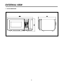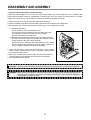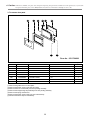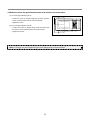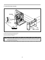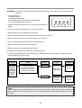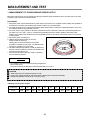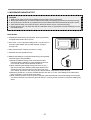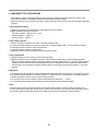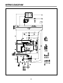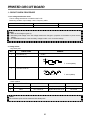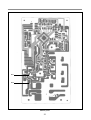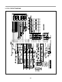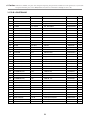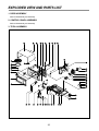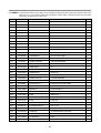
1
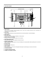
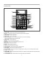
S/M No. : G867T9A001
Service Manual
Microwave Oven & Toaster
Model : KOG-867T
• Caution:
In this Manual, some parts can be changed for improving,
their performance without notice in the parts list. So, if you
need the latest parts information, please refer to PPL(Parts
Price List) in Service Information Center (http://svc.dwe.co.kr).
Sep. 2003
PRECAUTIONS TO BE OBSERVED BEFORE AND
DURING SERVICING TO AVOID POSSIBLE
EXPOSURE TO EXCESSIVE MICROWAVE ENERGY
(a) Do not operate or allow the oven to be operated with the door open.
(b) Make the following safety checks on all ovens to be serviced before activating the magnetron or other
microwave source, and make repairs if necessary: (1) Interlock operation, (2) Proper door closing, (3)
Seal and sealing surfaces (arcing, wear, and other damage), (4) Damage to or loosening of hinges and
latches (5) Evidence of dropping or abuse.
(c) Before turning on power to the microwave oven for any service test or inspection within the microwave
generating compartments, check the magnetron, wave guide or transmission line, and cavity for proper
alignment, integrity, and connections.
(d) Any defective or misadjusted components in the interlock, monitor, door seal and microwave
generation and transmission systems shall be repaired, replaced, or adjusted by procedures described
in this manual before the oven is released to the owner.
(e) A microwave leakage check to verify compliance with the Federal performance standard should be
performed on each oven prior to release to the owner.
TABLE OF CONTENTS
SAFETY AND PRECAUTIONS........................................................................................................................................3
FOR SAFE OPERATION ...........................................................................................................................................3
FOR SAFE SERVICE PROCEDURES .....................................................................................................................3
SPECIFICATIONS ............................................................................................................................................................4
EXTERNAL VIEW .............................................................................................................................................................5
OUTER DIMENSION .................................................................................................................................................5
FEATURE DIAGRAM.................................................................................................................................................6
CONTROL PANEL .....................................................................................................................................................7
INSTALLATION ................................................................................................................................................................8
OPERATION PROCEDURE(MICROWAVE OVEN)........................................................................................................9
IMPORTANT ...................................................................................................................................................................10
OPERATION PROCEDURE(TOASTER).......................................................................................................................11
DISASSEMBLY AND ASSMBLY...................................................................................................................................12
INTERLOCK MECHANISM AND ADJUSTMENT.........................................................................................................20
TROUBLE SHOOTING GUIDE ......................................................................................................................................21
MESUREMENT AND TEST............................................................................................................................................26
MEASUREMENT OF THE MICROWAVE POWER OUTPUT................................................................................26
MICROWAVE RADIATION TEST ...........................................................................................................................27
COMPONENT TEST PROCEDURE .......................................................................................................................28
WIRING DIAGRAM.........................................................................................................................................................29
PRINTED CIRCUIT BOARD...........................................................................................................................................30
CIRCUIT CHECK PROCEDURE.............................................................................................................................30
PCB CIRCUIT DIAGRAM ........................................................................................................................................33
P.C.B. LOCATION NO. ............................................................................................................................................34
EXPLODED VIEW AND PARTS LIST ...........................................................................................................................35
DOOR ASSEMBLY ..................................................................................................................................................35
CONTROL PANEL ASSEMBLY ..............................................................................................................................35
TOTAL ASSEMBLY .................................................................................................................................................35
TOAST ASSEMBLY (C00).......................................................................................................................................38
2
SAFETY ANDPRECAUTIONS
CAUTION : This Device is to be Serviced Only by Properly Qualified Service Personnel. Consult the Service
Manual for Proper Service Procedures to Assure Continued Safety Operation and for Precautions
to be Taken to Avoid Possible Exposure to Excessive Microwave Energy.
1. FOR SAFE OPERATION
Damage that allows the microwave energy (that cooks or heats the food) to escape will result in poor cooking and
may cause serious bodily injury to the operator.
IF ANY OF THE FOLLOWING CONDITIONS EXIST, OPERATOR MUST NOT USE THE APPLIANCE.
(Only a trained service personnel should make repairs.)
1) A broken door hinge.
2) A broken door viewing screen.
3) A broken front panel, oven cavity.
4) A loosened door lock.
5) A broken door lock.
The door gasket plate and oven cavity surface should be kept clean.
No grease, soil or spatter should be allowed to build up on these surfaces or inside the oven.
DO NOT ATTEMPT TO OPERATE THIS APPLIANCE WITH THE DOOR OPEN. The microwave oven has
concealed switches to make sure the power is turned off when the door is opened. Do not attempt to defeat them.
DO NOT ATTEMPT TO SERVICE THIS APPLIANCE UNTIL YOU HAVE READ THIS SERVICE MANUAL.
2. FOR SAFE SERVICE PROCEDURES
1) If the oven is operative prior to servicing, a microwave emission check should be performed prior to servicing
the oven.
2) If any certified oven unit is found to have excessive emission level 5mW/cm2, the service person should:
(a) inform the manufacturer, importer or assembler,
(b) repair the unit at no cost to the owner,
(c) attempt to ascertain the cause of the excessive leakage,
(d) tell the owner of the unit not to use the unit until the oven has been brought into compliance.
3) If the oven operates with the door open, the service person should tell the user not to operate the oven and
contact the manufacturer and CDRH immediately.
CAUTION
MICROWAVE RADIATION
PERSONNEL SHOULD NOT BE EXPOSED TO THE MICROWAVE ENERGY WHICH MAY RADIATE
FROM THE MAGNETRON OR OTHER MICROWAVE GENERATING DEVICE IF IT IS IMPROPERLY
USED OR CONNECTED. ALL INPUT AND OUTPUT MICROWAVE CONNECTIONS. WAVEGUIDES
FLANGES AND GASKETS MUST BE SECURED. NEVER OPERATE THE DEVICE WITHOUT A
MICROWAVE ENERGY ABSORBING LOAD ATTACHED. NEVER LOOK INTO AN OPEN WAVEGUIDE
OR ANTENNA WHILE THE DEVICE IS ENERGIZED.
3
SPECIFICATIONS
POWER SUPPLY
120V AC 60 Hz SINGLE PHASE WITH EARTHING
POWER CONSUMPTION
1.4 KW
OUTPUT POWER
1000 W
MICROWAVE
FREQUENCY
2450 MHz
OVEN
TIMER
59 min. 99 sec.
POWER LEVELS
10 LEVELS
CAVITY DIMENSIONS
320 x 244 x 338 mm (12.6 x 9.6 x 13.3 inch)
CAVITY VOLUME
0.9 Cu.ft
POWER CONSUMPTION
1.0 KW
TOASTER
OUTSIDE DIMENSIONS (W x H x D)
583 x 301 x 421 mm (22.9 x 11.8 x 16.5 inch)
NET WEIGHT
APPROX. 15.7 KG (34.3 lbs)
* Specifications are subject to change without notice.
IMPORTANT
The wires in this mains lead are colored in accordance with the following code.
Green-and-yellow
: Earth
Blue
: Neutral
Brown
: Live
As the colors of the wires in the mains lead of this appliance may not correspond with the colored markings
identifying the terminals in your plug, proceed as follows: the wire which is colored green-and-yellow must be
connected to the terminal in the plug which is marked with the letter 'E', the earth symbol or colored greenand-yellow. The wire which is colored blue must be connected to the terminal which is marked with the letter
'N' or colored black.
The wire which is colored brown must be connected to the terminal which is marked with the letter 'L' or
colored red.
WARNING: This appliance must be grounded.
4
EXTERNAL VIEW
1. OUTER DIMENSION
5
2. FEATURE DIAGRAM
MICROWAVE OVEN
2
3
TOASTER
4 5
0
1
q
9
8
7
6
w
1. DOOR LATCH
When the door is closed it will automatically shut off. If the door is opened while the oven is operating, the
magnetron will automatically shut off.
2. DOOR SEAL
The door seal maintains the microwave within the oven cavity and prevents microwave leakage.
3. OVEN CAVITY
4. SPATTER SHIELD
Protects the microwave outlet from splashes of cooking foods.
5. SAFETY INTERLOCK SYSTEM
Prevents the oven from operating while the door is opened.
6. DOOR RELEASE BUTTON
Pushing this button stops oven operation and opens the door.
7. GLASS COOKING TRAY
Made of special heat resistant glass. The tray must always be in proper position before operating. Do not cook food
directly on the tray.
8. ROLLER GUIDE
Supports the glass cooking tray.
9. DOOR SCREEN
Allows viewing of food. The screen is designed so that light can pass through, but not the microwaves.
10. TOASTER DRAWER
11. TOASTER OPENING HANDLE
12. CRUMB TRAY(REFER. PAGE10)
6
3. CONTROL PANEL
2
3
9
4
8
6
5
7
1
e
w
q
0
t
r
u
y
1. TIME SET PAD - Used to set the cooking time and the present time.
2. DISPLAY - Cooking time, power level, indicators and present time are displayed.
3. TOAST BREAD - Used to reheat bread.
4. TOAST BAGEL - Used to reheat bagel.
5. TOAST STOP/CLEAR - Used to stop the toast operation or to clear the toast setting.
Used to transfer toaster mode to microwave mode.
6. TOAST START - Used to toast start.
7. MEMORY - Used to set favorite cooking mode.
8. POPCORN - Used to cook or reheat specific quantities of food.
9. AUTO COOK - Used to cook or reheat.
10. MORE - Used to add time to cooking.
11. LESS - Used to remove time from cooking.
12. AUTO DEFROST - Used to defrost foods.(for weight and time)
13. MICROWAVE - Used to select microwave power level.
14. KITCHEN TIMER - Used as a minute timer, to delay the start of cooking, or to set a holding time after cooking.
15. CLOCK - Used to set clock.
16. STOP/CLEAR - Used to stop the Microwave operation or to delete the cooking data Used to transfer Microwave
mode to toaster mode.
17. START/SPEEDY COOK - Used to start the oven and also used to set a reheat time.
7
INSTALLATION
1. Steady, flat location
This microwave oven should be set on a steady, flat surface.
This microwave oven is designed for counter top use only.
2. Leave space behind and side
All air vents should be kept a clearance. If all vents are covered during operation, the oven may overheat and, eventually,
cause oven failure. Position the oven as far from them as passible.
3. Away from Radio and TV sets
Poor television reception and radio interference may result if the oven is located close to a TV, Radio, antenna or feeder
and so on.
4. Away from heating appliances and water taps
Keep the oven away from hot air, steam or splash when choosing a place to position it, or the insulation might be
adversely affected and breakdowns occur.
5. Power supply
➢ Check your local power source.
This microwave oven requires a current of approximately 12 amperes, 120Volts, 60Hz grounded outlet.
➢ Power supply cord is about 1.0 meters long.
➢ The voltage used must be the same as specified on this oven. Using a higher voltage may result in a fire or other
accident causing oven damage. Using low voltage will cause slow cooking. We are not responsible for damage resulting
from use of this oven with a voltage of ampere fuse other than those specified.
➢ This appliance is supplied with cable of special type, which, if damaged, must be repaired with cable of same type.
Such a cable can be purchased from DAEWOO and must be installed by a Qualified Person.
6. Examine the oven after unpacking for any damage such as:
A misaligned door, broken door or a dent in cavity.
If any of the above are visible, DO NOT INSTALL, and notify dealer immediately.
7. Do not operate the oven if it is colder than room temperature
(This may occur during delivery in cold weather.) Allow oven to become room temperature before operating.
GROUNDING INSTRUCTIONS
This appliance must be grounded. In the event of an electrical short circuit, grounding reduces the risk of the electric
shock by providing an escape wire for the electric current. This appliance is equipped with a cord having a grounding wire
with a grounding plug. The plug must be plugged into an outlet that is properly installed and grounded.
WARNING
Improper use of the grounding plug can result in a risk of electric shock. Consult a qualified electrician or serviceman if
the grounding instructions are not completely understood, or if doubt exists as to whether the appliance is properly
grounded, and either:If it is necessary to use an extension cord, use only a 3-wire extension cord that has a 3-blade
grounding plug, and a 3-slot receptacle that will accept the plug on the appliance. The marked rating of the extension
cord should be equal to or greater than the electrical rating of the appliance, or Do not use an extension cord.
8
OPERATION PROCEDURE(MICROWAVE OVEN)
This section includes useful information about Microwave oven operation.
1. Plug power supply cord into a standard 3-pronged 20Amp, 120V AC 60Hz poweroutput.
2. After placing the food in a suitable container, open the oven door and put it on the glass tray.
The glass tray and roller guide must always be in place during cooking.
3. Shut the Microwave oven door. Make sure that it is firmly closed.
oven light is on only when the microwave oven 7
1 The
is operating.
oven door can be opened at any time during
2 The
operation by touching the door release button on the
control panel. The oven will automatically shut off.
time a pad is touched, a BEEP sounds to
3 Each
acknowledge the touch.
8
oven automatically cooks on full power unless
4 The
set to a lower power level.
When the Microwave STOP/CLEAR pad is touched
during the oven operation, the oven stops cooking and all
information retained. To erase all information(except the
present time), touch the STOP/CLEAR pad once more.
If the oven door is opened during the oven operation, all
information is retained.
If the Microwave START pad is touched and the oven
does not operate, check the area between the door and
door seal for obstructions and make sure the door is
closed securely. The oven will not start cooking until the
door is completely closed or the program has been reset.
display will show “ : 0” when the oven is plugged
5 The
in.
Make sure the oven is properly installed and
plugged into the electrical outlet.
clock returns to the present time when the
6 Time
cooking time ends.
WATTAGE OUTPUT CHART
• The power-level is set by pressing the MICROWAVE pad. The chart shows the display, the power level and the
percentage of power.
Touch MICROWAVE pad
Power level (Display)
Approximate Percentage of Power
once
P-HI
100%
twice
P-90
90%
3 times
P-80
80%
4 times
P-70
70%
5 times
P-60
60%
6 times
P-50
50%
7 times
P-40
40%
8 times
P-30
30%
9 times
P-20
20%
10 times
P-10
10%
11 times
P-00
0%
9
IMPORTANT
Before using the toaster for the first time, operate the toaster without bread in order to burn off residues on the
heating elements. You will notice an odor that is characteristics of new heating elements. This is normal and will
soon disappear.
CLEANING THE TOASTER
Always unplug the Microwaves & Toaster and allow the toaster to cool completely before cleaning.
Toaster drawer:
Wipe surface with a soft, clean, damp cloth. Never use abrasive cleaners, as they may scratch the surface. Do not
use fork or other sharp, metal object to clean inside of the Toaster drawer, or to remove toast, as it may damage
heating elements.
Crumb Tray :
After allowing the toaster to cool down and closing the door, gently slide out the crumb tray. Brush crumbs off the
tray and, if necessary, wipe it with a clean, damp cloth. Always dry the tray thoroughly. When sliding the crumb
tray into place, be sure you feel and hear it snap into position.
COOKING TIPS
WARNING!
Never place any object in the toaster for any reason!
• DO NOT toast pastries with runny fillings or frosting.
• DO NOT toast torn slices of bread or broken pastries.
• DO NOT place buttered bread, wrapped food, or frozen pastries in the toaster.
• DO NOT use this toaster to toast or warm small-size bread slices. These include “melba” size breads, slices of
mini-baguettes, breadsticks, etc.
• DO NOT toast oversized bagel. Because thick bagel’s surface may become closer to the heater, this may cause
overdone of surface and smoke.
NOTE : Different types of bread and their moisture levels may require different darkness settings. For
example, dry bread will brown more rapidly than moist bread and so will be toasted to your taste at a
lighter setting.
NOTE : 2 pieces of bread or bagel should be cooked with this toaster.
10
OPERATION PROCEDURE(TOASTER)
This section includes useful information about toaster operation.
1. Plug power supply cord into a standard 3-pronged 20Amp, 120V AC 60Hz poweroutput.
2. Put 2 pieces of toast bread or bagel between the toaster guides (wire rack) of the toaster drawer.
3. Shut the toaster drawer. Make sure that it is firmly closed.
toaster drawer can be opened at any time during operation by pulling out the toaster handle on the toaster
1 The
drawer. The toaster will automatically shut off.
2 Touch the bread or bagel pad of toast menu and the degree of darkness will be displayed.
3 Each time a pad is touched, a BEEP sounds to acknowledge the touch.
toaster start pad and then the toast indicator linght is on and the best cooking time is displayed
4 Touch
according to the condition of the toaster (not in the case of time toasting) and toast cooking starts. During the
toast cooking, hot smoke or air may goes out from the gap of the toaster drawer.
the toast STOP/CLEAR pad is touched during the oven operation, the toaster stops cooking and all
5 When
information retained. To erase all information(except the present time), touch the STOP/CLEAR pad once
more. If the toaster drawer is opened during the toaster operation, all information is retained.
the toast START pad is touched and the toaster does not operate, check the toaster drawer is closed
6 Ifsecurely.
The toaster will not start cooking until the toaster drawer is completely closed or the program has
been reset.
NOTE :
When the toaster drawer is opened after toast cooking, hot smoke or air will go out and the toaster guides
(wire rack) are very hot.
Take out food carefully not to touch hot surfaces of the toaster or hot air.
NOTE :
When the toaster is operated several times in series and is overheated, the safety thermal switch works
and the heating elements stop operating. So, though the toaster seems to operate normally, it does not
cook toast.
Open the toaster drawer and cool it for 5~6 min.
After then the toaster can cook toast normally.
NOTE :
When you start toast cooking (br-1~br-3 and bg-1~bg-3) within 1 min. in series after toast cooking, the
toaster starts cooking with cooling time automatically added to the cooking time.
NOTE :
When you start toast cooking, the best cooking time is displayed according to the condition of the toaster.
(br-1~br-3: 1 min. 20 sec.~2 min. 40 sec/ bg-1~bg-3: 1min. 20 sec.~2 min. 45 sec.)
11
DISASSEMBLY AND ASSEMBLY
- Cautions to be observed when trouble shooting.
Unlike many other appliances, the microwave oven is high-voltage, high-current equipment. It is completely safe
during normal operation. However, carelessness in servicing the oven can result in an electric shock or possible
danger from a short circuit. You are asked to observe the following precautions carefully.
1. Always remove the power plug from the outlet before servicing.
2. Use an insulated screwdriver and wear rubber gloves when servicing the high voltage side.
3. Discharge the high voltage capacitor before touching any oven components or wiring.
(1) Check the grounding.
Do not operate on a two-wire extension cord.
The microwave oven is designed to be used while grounded.
It is imperative, therefore, to make sure it is grounded
properly before beginning repair work.
(2) Warning about the electric charge in the high voltage capacitor.
For about 30 seconds after the operation has stopped, electric
charge remains in the high voltage capacitor.
When replacing or checking parts, short between oven chassis
and the negative high terminal of the high voltage capacitor by
using a properly insulated screwdriver to discharge.
4. When the 20A fuse is blown due to the operation of the monitor
switch; replace primary interlock switch, secondary interlock switch
and interlock monitor switch.
5. After repair or replacement of parts, make sure that the screws are
properly tightened, and all electrical connections are tightened.
6. Do not operate without cabinet.
CAUTION : Service personnel should remove their watches whenever working close to or replacing the magnetron.
WARNING : When servicing the appliance, take care when touching or replacing high potential parts because of
electrical shock or exposing microwave. These parts are as follows - HV Transformer, Magnetron,
HV Capacitor, HV Diode, HV Fuse.
12
1. To remove cabinet
1) Remove three screws on cabinet back.
2) Push the cabinet backward.
2. To remove door assembly
1) Remove two screws which secure the stopper hinge top.
2) Remove the door assembly from top plate of cavity.
3) Reverse the above for reassembly.
NOTE : After replacing the door assembly, perform a check of correct alignment with the hinge and cavity front plate.
13
✔ Caution: In this Service Manual, some parts can be changed for improving, their performance without notice in the parts list. So, if you need the
latest parts information, please refer to PPL(Parts Price List) in Service information Center(http://svc.dwe.co.kr)
3. To remove door parts.
Door As : 3511724200
REF NO.
PART CODE
PART NAME
A01
3517008600
BARRIER SCREEN*O
A02
3511724400
A03
3511711800
A04
DESCRIPTION
Q’TY
SAN T1.5
1
DOOR SUB AS
KOG-867T9
1
DOOR PAINTING AS
KOR-86670S
1
3515204100
STOPPER HINGE*T AS
KOR-63150S
1
A05
3517006000
BARRIER SCREEN*I
PE T0.1
1
A06
3512302000
GASKET DOOR
PP
1
A07
3513100700
HOOK
POM
1
A08
3515101300
SPRING HOOK
PW-1
1
(1) Remove the gasket door from door plate.
(2) Remove the barrier screen inner from door plate.
(3) Remove the door sub assembly from door painting assambly.
(4) Remove the stopper hinge top assembly from door painting assambly.
(5) Remove the spring and the hook.
(6) Remove the barrier screen outer from door sub assembly.
(7) Reverse the above steps for reassembly.
14
4. Method to reduce the gap between the door seal and the oven front surface.
(1) To reduce gap located on part ‘A’.
• Loosen the screw on stopper hinge top, and then push the
door to contact the door seal to oven front surface.
• Tighten the screw.
(2) To reduce gap located on part ‘B’.
• Loosen two screws on stopper hinge under, and then push
the door to contact the door seal to oven front surface.
• Tighten two screws.
NOTE : A small gap may be acceptable if the microwave leakage does not exceed 4mW/cm2.
15
5. To take off the toaster assembly.
(1) Remove four screws on the toaster assembly.
(2) Lift up the toaster assembly and pull it out.
(3) Reverse the above for assembly.
NOTE : To assemble the toaster assembly, push two taps on the side of the toaster front plate into two rectomgular
holes of the front plate securely. And push two rectangular holes of the bottom of the toaster front plate into
two vertical taps of the base plate.
16
✔ Caution: In this Service Manual, some parts can be changed for improving, their performance without notice in the parts list. So, if you need the
latest parts information, please refer to PPL(Parts Price List) in Service information Center(http://svc.dwe.co.kr)
6. To remove control panel parts.
REF NO.
PART CODE
PART NAME
DESCRIPTION
Q’TY
B01
3518524400
SWITCH MEMBRANE
KOG-867T9
1
B02
3516731100
CONTROL PANEL
ABS VE-0826 AF-348
1
B03
PKMPMSAY00
PCB AS
KOG-867T9
1
B04
7122401211
SCREW TAPPING
T2S TRS 4X12 MFZN
4
B05
3513702700
LEVER DOOR LOCK
PP
1
B06
441G430171
BUTTON SPRING
SWP DIA 0.7
1
B07
3516912300
BUTTON DOOR OPEN
ABS SG-175 SG-0760D
1
(1) Remove the screw which secure the control panel, push up two snap fits and draw forward the control panel assembly.
(2) Remove the door open lever from the control panel.
(3) Remove four screws which secure the PCB assembly to control panel.
(4) Disconnect membrane tail from the connector of the PCB assembly.
(5) Detach membrane from the control panel.
(6) Remove door open button and button spring from the control panel.
(7) Reverse the above steps for reassembly.
17
7. To remove high voltage capacitor.
1) Remove a screw which secure the grounding ring
terminal of the H.V. diode and the capacitor holder.
2) Remove the H.V. diode from the capacitor holder.
3) Reverse the above steps for reassembly.
8. High voltage circuit wiring
9. To remove magnetron.
1) Remove a screw which secure the magnetron.
2) Remove the magnetron.
3) Reverse the above steps for reassembly.
NOTE : Never install the magnetron without the metallic gasket plate which is packed with each magnetron to
prevent microwave leakage. Whenever repair work is carried out on magnetron, check the microwave
leakage. It shall not exceed 4mW/cm2 for a fully assembled oven with door normally closed.
Metallic
gasket
plate
Magnetron
antenna
Cooling fin
Filament
terminal
18
10. To remove wind guide assembly.
1) Remove a screw which secure the wind guide assembly.
2) Draw forward the wind guide assembly.
3) Pull the fan from the motor shaft.
4) Remove two screws which secure the motor shaded pole.
5) Remove the motor shaded pole.
6) Reverse the above steps for reasembly.
11. To remove H.V.transformer.
1) Remove four screws holding the H.V.transformer.
2) Remove the H.V.transformer.
3) Reverse the above steps for reassembly.
19
INTERLOCK MECHANISM AND ADJUSTMENT
The door lock mechanism is a device which has been specially designed to completely eliminate microwave radiation when
the door is opened during operation, and thus to perfectly prevent the danger resulting from the leakage of microwave.
Toast Panel Top
GN
WH/BK
RD
RD/RD
Spring
BL/BK
Condition : Toast Drawer Open
BK
GN
BL
Toast interlock switch
BL
Condition : DOOR CLOSE
Condition : DOOR OPEN
Condition : Toast Drawer Close
(1) Primary interlock switch
When the door is closed, the hook locks the oven door. If the door is not closed properly, the oven will not operate.
When the door is closed, the hook pushes the button of the micro switch. Then the button of the primary interlock switch
bring it under NO condition.
(2) Secondary interlock switch and interlock monitor switch
When the door is closed, the hook pushes the lock lever downward. The lock lever presses the button of the interlock
monitor switch to bring it under NC condition. The lock lever presses the button of the secondary interlock switch to bring
it under NO condition.
(3) Toast interlock switch
When the toast drawer is closed, the lever pushes the button of the micro switch.
Then the button of the toast interlock switch bring it under NO condition.
ADJUSTMENT :
Interlock monitor switch
When the door is closed, the interlock monitor switch should be changed (NC condition) before other switches are closed.
When the door is opened, the interlock monitor switch should be changed (NO condition) after other switches are opened.
(4) Adjustment steps
a) Loosen the one mounting screw.
b) Adjust interlock switch assembly position.
c) Make sure that lock lever moves smoothly after adjustment is completed.
d) Tighten completely two mounting screws.
NOTE :
Microwave emission test should be performed after adjusting interlock mechanism.
If the microwave emission exceed 4mW/cm2, readjust interlock mechanism.
20
TROUBLE SHOOTING GUIDE
Following the procedure below to check if the oven is defective or not.
1) Check grounding before trouble checking.
2) Be careful of the high voltage circuit.
3) Discharge the high voltage capacitor.
4) When checking the continuity of the switches, fuse or high voltage tranformer, disconnect one load wire from these
parts and check continuity with the AC plug removed. To do otherwise may result in a false reading or damage to
your meter.
NOTE : When electric parts are checked, be sure the power cord is not inserted the wall outlet.
Check wire harness, wiring and connection of the terminals and power cord before check the parts listed below.
(TROUBLE 1) Oven does not operate at all : any inputs can not be accepted.
CONDITION
CHECK
Fuse blows.
Check continuity of interlock
monitor switch with door closed
(COM ↔ NC)
RESULT
Continuity
CAUSE
Malfunction of
interlock
monitor switch
REMEDY
Replace
NOTE 1
No Continuity
Check continuity of both
primary and secondary
interlock switch with door
closed
No Continuity
Continuity
Continuity
Check continuity of primary
interlock switch contact with door
partially open until interlock
monitor switch contact close
(COM ↔ NC)
Check continuity of primary
winding of low voltage
transformer
0Ω or infinite
Approx.
1160 Ω
(normal)
Fuse again
blows
Disconnect high voltage fuse
and operate the unit
21
Replace
Malfunction of
interlock switch
Shorted contacts
of primary
interlock switch.
Defective low
voltage
transformer
Defective high
voltage
transformer
NOTE 1
Replace
NOTE 1
Replace
Replace
CONDITION
Outlet has
proper
voltage Fuse
does not
blow.
CHECK
RESULT
CAUSE
REMEDY
No
Continuity
Defective
magnetron
Replace
Check continuity of magnetron
Check continuity of
noise filter board
No
Continuity
Defective line
filter board
Replace
Check continuity of
power supply cord
No
Continuity
Open power
supply cord
Replace
Normal
Defective touch
control circuit
Adjust
NOTE 1
All these switches must be replaced at the same time, please refer to “Interlock Mechanism And Adjustment”.
(TROUBLE 2) Display shows all figures selected, but oven does not start cooking, even though desired program and
time are set and start pad is pressed.
CONDITION
CHECK
RESULT
CAUSE
REMEDY
Turntable
motor and
oven lamp
do not turn
on
Check continuity of primary
interlock switch
No
Continuity
Malfunction of
primary interlock
switch
Adjust or
replace
Check continuity of secondary
interlock and D.O.M. switches
No
Continuity
Malfunction of
primary interlock
and D.O.M.
switch
Adjust or
replace
Check D.C. voltage being
supplied to RELAY (RY2) coil
0V
Defective touch
control circuit
Replace
Approx.
15 VDC
Faulty contacts of
RELAY (RY2) or
open relay coil
22
Replace
(TROUBLE 3) No microwave oscillation even though fan motor rotates.
CONDITION
CHECK
RESULT
CAUSE
REMEDY
No
microwave
oscillation
Check continuity of
high voltage fuse
No
continuity
Defective
high voltage
fuse
Replace
Check continuity of
high voltage capacitor terminals
with wires removed
Continuity
Defective
high voltage
transformer
1
Check continuity of
high voltage rectifier in forward
and backward
direction with DC megger
Continuity
in backward
direction
Defective high
voltage rectifier
Replace
No microwave oscillation
Connect megger leads to
magnetron terminal and
magnetron body
Continuity
Defective
magnetron
2
Check D.C voltage
being supplied to
RELAY (RY1) coil
0V
Defective
touch control
circuit
Replace
Approx.
15V DC
Faulty contacts of
RELAY
(RY1) or open
relay coil
Replace
Defective
high voltage
transformer
Replace
Defective high
voltage
transformer
Replace
Defective
magnetron
Replace
0 Ω or ∞
1 Check resistance of primary
and secondary coil of high
voltage transformer
1 Check continuity of filament
No continuity
terminal of high voltage
transformer
2 Check continuity of
magnetron heater with wires
removed
No continuity
23
(TROUBLE 4)
Toaster heater is not heated; bread or bagel will not toast.
CONDITION
CHECK
RESULT
CAUSE
Toaster
heater is
not heated.
Check continuity of
spring flat
No
continuity
Malfunction of
spring flat
Check continuity of
interlock switch
No
continuity
Malfunction of
interlock switch
Check continuity of
- heater assy
No
continuity
Defective heater
assy
Replace
Check D.C voltage
being supplied to
RELAY (RY3) coil
0V
Defective touch
control circuit
Replace
Approx.
15V DC
Faulty contacts of
RELAY
(RY3) or open
relay coil
Replace
CHECK
RESULT
CAUSE
REMEDY
Check continuity of
primary interlock switch
No
continuity
Malfunction of
primary Interlock
switch
Adjust or
replace
Check continuity of
secondary interlock
switch
No
continuity
Malfunction of
secondary
interlock switch
Adjust or
replace
Check continuity of
(heater or motor)
No
continuity
Defective motor
Check D.C voltage
being supplied to
RELAY (RY4) coil
0V
Defective touch
control circuit
Replace
Approx.
15V DC
Faulty contacts of
RELAY
(RY4) or
open relay coil
Replace
REMEDY
Adjust or
replace
Adjust or
replace
(TROUBLE 5)
1) Fan motor does no rotate.
CONDITION
1)Fan
motor does
not rotate.
24
Replace
(TROUBLE 6) The following visual conditions indicate a probable defective touch control circuit or membrane switch
assembly
1. Incomplete segments,
1) Segments missing.
2) Partical segments missing.
3) Digit flickering other than normal display slight flickering.
4) " :0" does not display when power is on.
2. A distinct change in the brightness of one or more numbers exists in the
display.
M/W
TOAST
DEF. TIMER
lb
3. One or more digits in the display are not on when they should be.
4. Display indicates a number different from one touched.
5. Specific numbers (for example 2 or 3) will not display when the panel is touched.
6. Display does not count down or up with time cooking or clock operation.
7. Oven is programmable and cooks normally but no display shows.
8. Display obviously jumps in time while counting down.
9. Display counts down noticeably too fast while cooking.
10. Display does not show the time of day when clear pad is touched.
11. Oven lamp and turntable motor do not stop although cooking is finished. Check if the RELAY 2 contacts close if they
are close, replace touch control circuit.
CONDITION
CHECK
Display does
not show
programming
at all, even if
keyboard is
touched.
Check each pad for
continuity of the membrane
keyboard for the following
keyboard check procedure
RESULT
CAUSE
REMEDY
Normal
Malfunction
of pcb assembly
Abnormal
Malfunction
of the membrane
keyboard
Replace pcb
assembly
Replace the
membrane
keyboard
NOTE
Before following the particular steps listed above in the trouble shooting guide for the membrane keyboard's,
failure, please check for the continuity of each wire-harness between the membrane keyboard and P.C.B.
assembly.
25
MEASUREMENT AND TEST
1. MEASUREMENT OF THE MICROWAVE POWER OUTPUT
Microwave output power can be checked by indirectly mmeasuring the temperature rise of a certain amount of water
exposed to the microwave as directed below.
PROCEDURE
1. Microwave power output measurement is made with the microwave oven supplied at rated voltage and operated at
its maximum microwave power setting with a load of 1000 ± 5cc of potable water.
2. The water is contained in a cylindrical borosilicate glass vessel having a maximum material thickness of 3 mm and
an outside diameter of approximately 190 mm.
3. The oven and the empty vessel are at ambient temperature prior to the start of the test. The initial temperature of
the water is 10 ± 2°C (50 ± 3.6°F). If is measured immediately before the water is added to the vessel. After
addition of the water to the vessel, the load is immediately placed on the center of the shelf, which is in the lowest
normal position.
4. Microwave power is switched on.
5. Heating time should be exactly A seconds.
(Refer to table as following)
Heating time is measured while the microwave
generator is operating at full power. The filament heatup time for magnetron is not included.
6. The initial and final temperature of water is selected so
that the maximum difference between the ambient and
final water temperature is 5K.
7. The microwave power output P in watts is calculated
from the following formula:
P=
4187 X ∆T
t
• ∆ T is difference between initial and ending temperature.
• t is the heating time.
The power measured be B (Refer to SPECIFICATIONS) W ± 10.0 %.
CAUTION
1. Water load should be measured exactly to 1 liter.
2. Input power voltage should be exactly specified voltage (Refer to SPECIFICATIONS).
3. Ambient temperature should be 20 ± 2°C (68 ± 3.6°F)
✻ Heating time for power output:
A (second)
70
64
60
56
52
49
47
44
42
40
38
B (W)
600
650
700
750
800
850
900
950
1000
1050
1100
26
2. MICROWAVE RADIATION TEST
CAUTION
1. Make sure to check the microwave leakage before and after repair of adjustment.
2. Always start measuring of an unknown field to assure safety for operating personnel from microwave energy.
3. Do not place your hands into any suspected microwave radiation field unless the safe density level is known.
4. Care should be taken not to place the eyes in direct line with the source of microwave energy.
5. Slowly approach the unit under test until the radiometer reads an appreciable microwave leakage from the
unit under the test.
PROCEDURE
1. Prepare Microwave Energy Survey Meter, 600cc glass beaker,
and glass thermometer 100°C (212°F).
2. Pour 275cc ± 15cc of tap water initially at 20 ± 5°C (68 ± 9°F) in
the 600 cc glass beaker with an inside diameter of approx.
8.5cm(3.5 in.).
3. Place it at the center of the tray and set it in a cavity.
4. Close the door and operate the oven.
5. Measure the leakage by using Microwave Energy Survey Meter
with dual ranges, set to 2450MHz.
1) Measured radiation leakage must not exceed the value
prescribed below. Leakage for a fully assembled oven with
door normally closed must be less than 4mW/cm2.
2) When measuring the leakage, always use the 5 cm (2 in.)
space cone with probe. Hold the probe perpendicular to the
cabinet and door. Place the space cone of the probe on the
door, cabinet, door seem, door viewing screen, the exhaust air vents and the suction air vents.
3) Measuring should be in a counter-clockwise direction at a rate of 1 in./sec. If the leakage of the cabinet door
seem is unknown, move the probe more slowly.
4) When measuring near a corner of the door, keep the probe perpendicular to the areas making sure the probe
end at the base of the cone does not get closer than 2 in. from any metal. If it does not, erroneous reading may
result.
27
3. COMPONENT TEST PROCEDURE
• High voltage is present at the high voltage terminal of the high voltage transformer during any cooking cycle.
• It is neither necessary nor advisable to attempt measurement of the high voltage.
• Before touching any oven components or wiring, always unplug the oven from its power source and discharge the
capacitor.
1. High voltage transformer
1) Remove connections from the transformer terminals and check continuity.
2) Normal readings should be as follows :
Secondary winding ... Approx. 110 Ω±10%
Filament winding ... Approx. 0 Ω
Primary winding ... Approx. 1 Ω
2. High voltage capacitor
1) Check continuity of capacitor with meter on the highest OHM scale.
2) A normal capacitor will show continuity for a short time, and then indicate 10MΩ once the capacitor charged.
3) A shorted capacitor will show continuous continuity.
4) An open capacitor will show constant 10MΩ.
5) Resistance between each terminal and chassis should be infinite.
3. High voltage diode
1) Isolate the diode from the circuit by disconnecting the leads.
2) With the ohmmeter set on the highest resistance scale measure the resistance across the diode terminals.
Reverse the meter leads and again observe the resistance reading. Meter with 6V, 9V or higher voltage batteries
should be used to check the front-back resistance of the diode, otherwise an infinite resistance may be read in
both directions. A normal diode's resistance will be infinite in one direction and several hundred kΩ in the other
direction.
4. Magnetron
For complete magnetron diagnosis, refer to "Measurement of the Microwave Power Output." Continuity checks can
only indicate and open filament or a shorted magnetron. To diagnose for an open filament or a shorted magnetron,
1) Isolate magnetron from the circuit by disconnecting the leads.
2) A continuity check across magnetron filament terminals should indicate 0.1 Ω or less.
3) A continuity check between each filament terminal and magnetron case should read open.
5. Fuse
If the fuse in the primary and monitor switch circuit is blown when the door is opened, check the primary and
monitor switch before replacing the blown fuse. In case the fuse is blown by an improper switch operation, replace
the defective switch and fuse at the same time. Replace just the fuse if the switches operate normally.
28
WIRING DIAGRAM
29
PRINTED CIRCUIT BOARD
1. CIRCUIT CHECK PROCEDURE
1. Low voltage transformer check
The low voltage transformer is located on the P.C.B.
Measuring condition: Input voltage: 120V / Frequency: 60Hz
Terminal Voltage
LOAD
NO LOAD
7-8
AC
AC 14.5 V
NOTE
1. Refer to Ciruit Diagram (point 4).
2. Secondary side voltage of the low voltage transformer changes in proportion to fluctuation of power source
voltage.
3. The allowable tolerance of the secondary voltage is within ± 5% of nominal voltage.
2. Voltage Check
- Key check point
NO
CHECK POINT
1
IC1 PIN 40, 18
2
IC1 PIN 29(INT)
REMARK
+5VDC
T : 16.67ms(60Hz)
3
IC1 PIN 15 OR 16
T : 250 ns(4MHz)
- Check method
NO
MEASURE POINT
WAVE FORM
REMEDY
REMARK
1
MP1
DC +5V±0.25V
Replace VL1, EC1
NO LOAD
2
MP2
DC +12V±2.0V
Replace EC2, D12,14,15
NO LOAD
NOTE
Each measure point must be measured with GND points.
30
MP1
MP2
Mesure point
31
3. When there is no microwave oscillation
1) When touching START pad, oven lamp turns on and turntable rotates.
but cook indicator in display comes on.
✻ Cause : RELAY 4 does not operate. → refer to Circuit Diagram (point 3)
- Check method
POINT
A
B
RELAY 4 ON
+5VDC
GND
RELAY 4 OFF
GND
+15VDC
STATE
2) When touching START pad, oven lamp turns on.
Fan motor and turntable rotate and cook indicator in display comes on.
✻ Cause : RELAY 1 does not operate. → refer to Circuit Diagram (point 2)
- Check method
POINT
A
B
RELAY 1 ON
+5VDC
GND
RELAY 1 OFF
GND
+15VDC
STATE
4. When toaster heater is not heated.
✻ Cause : RELAY 3 does not operate. → refer to Circuit Diagram (point 6)
- Check method
POINT
A
B
RELAY 3 ON
+5VDC
GND
RELAY 3 OFF
GND
+15VDC
STATE
5. When the door is opened during operation, the count down timer does not stop.
→ refer to Circuit Diagram (point 1)
- Check method
POINT
A
B
1) DOOR OPEN
OPEN
+5VDC
2) DOOR CLOSED
CLOSE
GND
STATE
CHECK NO
1
HETHOD
REMEDY
Check the stage(ON, OFF) of the door open monitor
switch by resistance measurement.
6. When the digital clock does not operate properly.
→ refer to Circuit Diagram (point 5)
POINT
A
WAVE FORM
T: 16.67 ms(60Hz)
❈ If clock does not keep exact time, you must check R21,R20,Q11,C7,C6.
32
Replace door open monitor switch.
2. P.C.B. CIRCUIT DIAGRAM
33
✔ Caution: In this Service Manual, some parts can be changed for improving, their performance without notice in the parts list. So, if you need the
latest parts information, please refer to PPL(Parts Price List) in Service information Center(http://svc.dwe.co.kr)
3. P.C.B. LOCATION NO
NO
NAME
SYMBOL
SPECIFICATION
PART CODE
Q’TY
1
PCB MAIN
M253
82X153
3514329800
1
2
BUZZER
BZ1
BM-20K
3515600100
1
3
C ARRAY
CA1
7P(6) 1000PF M 50V
CN6XB-102M
1
4
C CERA
C1~C6,C8
50V 104Z AXIAL
CCZF1H104Z
7
5
C CERA
C7
50V 102Z AXIAL
CCZB1H102K
1
6
C ELECTRO
EC1
50V RS 1MF
CEXE1H109A
1
7
C ELECTRO
EC2
25V RSS 1000MF
CEXF1E102V
1
8
CONNECTOR WAFER
CN1
YW396-03V
3519150530
1
9
CONNECTOR WAFER
CN2
FCZ 254-11
441M367160
1
10
CONNECTOR WAFER
CN3
YW396-07AV
3519150540
1
11
LED DISPLAY
DP1
LTC-4651HG(631)
DDDG631H02
1
12
DIODE
D1~D14
1N4148
DZN4148---
14
13
DIODE
D15,D16
1N4004A
DZN4004A--
2
14
DIODE ZENER
ZD1
UZ-3.3BSB 1/2W
DZUZ3R3BSB
1
15
IC MICOM
IC1
TMP87CH47U
13GL87PH47
1
16
IC REGULATOR
VL1
MC7805C
1CPMC7805C
1
17
R ARRAY
RA1
5P(4) 1/8 100K 5%
RA-85X104J
1
18
R ARRAY
RA2
7P(6) 1/8 100K 5%
RA-87X104J
1
19
R CARBON FILM
R19
1/4W 51 5%
RD-4Z510J-
1
20
R CARBON FILM
R11
1/6W 100 5%
RD-AZ101J-
1
21
R CARBON FILM
R1~R7
1/6W 330 5%
RD-AZ331J-
7
22
R CARBON FILM
R10,R13~R16,R22
1/6W 1K 5%
RD-AZ102J-
6
23
R CARBON FILM
R21
1/6W 47K 5%
RD-AZ473J-
1
24
R CARBON FILM
R9,R20
1/6W 10K 5%
RD-AZ103J-
2
25
R CARBON FILM
R17,R18
1/6W 100K 5%
RD-AZ104J-
2
26
R CARBON FILM
R8
1/6W 1M 5%
RD-AZ105J-
1
27
RESONATOR CERA
CR1
CRT 4.00MS
5P4R00MTS-
1
28
TRANSISTOR
Q1~Q5
KRA106M
TZRA106M--
5
29
TRANSISTOR
Q7~Q12
KRC106M
TZRC106M--
6
30
TRANSISTOR
Q6
KTA-1266Y
TZTA1266Y-
1
31
TRANS POWER
LVT1
DMR-161P
5EPU035303
1
32
SW RELAY
RY1,RY3
G5G-1A DC12V
5SC0101121
2
33
SW RELAY
RY2,RY4
CS11-12SH 1C 1P
5SC0101128
2
34
WIRE COPPER
J5~J8
1/0.52 TIN COATING
85801052GY
4
35
WIRE COPPER
J1~J4,J9~J13
1/0.52 TIN COATING
85801052GY
9
36
WIRE COPPER
SJ3,SJ4
1/0.52 TIN COATING
85801052GY
1
34
EXPLODED VIEW AND PARTS LIST
1. DOOR ASSEMBLY
Refer to Disassembly and assembly
2. CONTROL PANEL ASSEMBLY
Refer to Disassembly and assembly
3. TOTAL ASSEMBLY
35
✔ Caution : In this Service Manual, some parts can be changed for improving, their performance without notice in the
parts list. So, if you need the latest parts information, please refer to PPL(Parts Price List) in Service
Information Center (http://svc.dwe.co.kr).
NO
PART CODE
A00
3511724200
B00
PKCPSWAY00
C00
PART NAME
DESCRIPTION
Q'TY
DOOR AS
KOG-867T9A02
1
CONTROL PANEL AS
KOG-867T9A02
1
3510021100
ASSY TOASTER
KOG-867T9A02
1
F01
3510808010
CABINET
STS430 T0.5 H/L
1
F02
3516004100
SPECIAL SCREW
T1 TRS LR4 POLE 4X10 MFZN
4
F03
3516109900
CAVITY AS
KOR-86150S
1
F04
7122401211
SCREW TAPPING
T2S TRS 4X12 MFZN
1
F05
7122401211
SCREW TAPPING
T2S TRS 4X12 MFZN
1
F06
7112401011
SCREW TAPPING
T1 TRS 4X10 MFZN
1
F07
35113TCN35
CORD POWER AS
3X16 AWG 40X40 120-RTML
1
F08
7122401211
SCREW TAPPING
T2S TRS 4X12 MFZN
1
F09
7121300611
SCREW TAPPING
T2S PAN 3X6 MFZN
1
F10
3518902600
THERMOSTAT
OFF:90 ON:60 H#187
1
F11
7112401011
SCREW TAPPING
T1 TRS 4X10 MFZN
4
F12
7121402511
SCREW TAPPING
T2S PAN 4X25 MFZN
2
F13
3963821610
MOTOR SHADED POLE
120V 60HZ MW10XA-MO1
1
F14
3512517000
GUIDE WIND
PP
1
F15
3511800300
FAN
PP +30% GLASS
1
F16
3518002400
MAGNETRON
2M218J (F)
1
F17
3516004000
SPECIAL SCREW
T2 BOLT FLANGE 5X12 DACRO
1
F18
7272400811
SCREW TAPTITE
TT3 TRS 4X8 MFZN
1
F19
3513003200
HOLDER HV CAPACITOR
SECC T0.6
1
F20
3518302001
CAPACITOR HV
2100VAC 0.91UF #187 70MM
1
F21
3518400400
DIODE HV
HVR-1X-3AB 12KV #187
1
F22
3518118920
TRANS HV
DT-R11A0-1BT S
1
F23
3516003700
SPECIAL SCREW
TT3 HEX 4X8 FLG MFZN
4
F24
3510315600
BASE
SBHG T0.6
1
F25
7112401011
SCREW TAPPING
T1 TRS 4X10 MFZN
5
F26
3512101400
FOOT
DASF-310
4
F27
7272400811
SCREW TAPTITE
TT3 TRS 4X8 MFZN
1
F28
3515201101
STOPPER HINGE *U
SCP-1 T2.5
1
F29
4415A17352
SW MICRO
VP-533A-OF SPNO #187 200G
1
F30
4415A66600
SW MICRO
VP-532A-OF/SPNC #187 200G
1
F31
3518571000
SWITCH PUSH
MP101C
1
F32
3513702600
LEVER LOCK
POM
1
F33
3513811700
LOCK
POM
1
36
✔ Caution: In this Service Manual, some parts can be changed for improving, their performance without notice in the parts list. So, if you need the
latest parts information, please refer to PPL(Parts Price List) in Service information Center(http://svc.dwe.co.kr)
NO
PART CODE
PART NAME
DESCRIPTION
F34
3513601500
LAMP
BL 120V 25W T25 C5A H187
1
F35
5F1CD2031S
FUSE
125V 20A 65TS
1
F36
3512767900
HARNESS MAIN
KOG-867T9A02
1
F37
7121400611
SCREW TAPPING
T2S PAN 4X6 MFZN
1
F38
3966821000
MOTOR SYNCRO
120V 60HZ TYJ50-8
1
F39
7272400811
SCREW TAPTITE
TT3 TRS 4X8 MFZN
1
F40
3511406200
COVER WAVE GUIDE
HEATPROOF PP
1
F41
3517400620
COUPLER
XAREC
1
F42
3514700900
ROLLER
TEFLON
3
F43
3512513610
GUIDE ROLLER
XAREC
1
F44
3517203510
TRAY
GLASS
1
F45
7113400814
SCREW TAPPING
T1 BIN 4X8 MFNI
2
37
Q'TY
4. TOAST ASSEMBLY (C00)
38
✔ Caution: In this Service Manual, some parts can be changed for improving, their performance without notice in the parts list. So, if you need the
latest parts information, please refer to PPL(Parts Price List) in Service information Center(http://svc.dwe.co.kr)
NO
PART CODE
PART NAME
DESCRIPTION
C01
3510021300
ASSY PANEL TOP
KOG-867T9A02
1
C02
3511410800
COVER FRONT
PBT
1
C03
7112401011
SCREW TAPPING
T1 TRS 4X10 MFZN
2
C04
3514501900
PLATE FRONT
SBHG T0.6
1
C05
7122401211
SCREW TAPPING
T2S TRS 4X12 MFZN
1
C06
3514502000
PLATE SIDE
SECC T0.5
1
C07
7112401011
SCREW TAPPING
T1 TRS 4X10 MFZN
2
C08
3518903400
THERMOSTAT
OFF:150 ON:60 V H#187
1
C09
7121300611
SCREW TAPPING
T2S PAN 3X6 MFZN
1
C10
7112401011
SCREW TAPPING
T1 TRS 4X10 MFZN
6
C11
3514502100
PLATE TOP
SBHG T0.4
1
C12
3510021200
ASSY HEATER
KOG-867T9A02
1
C13
3514502200
PLATE REAR
SECC T0.6
1
C14
7112401011
SCREW TAPPING
T1 TRS 4X10 MFZN
2
C15
7112401011
SCREW TAPPING
T1 TRS 4X10 MFZN
1
C16
7122400811
SCREW TAPPING
T2S TRS 4X8 MFZN
2
C17
3515205000
STOPPER TOAST DRAWER
PBT
2
C18
3510021400
ASSY TOAST DRAWER
KOG-867T9A02
1
C19
3510021500
ASSY TRAY CRUMB
KOG-867T9A02
1
39
Q'TY
DAEWOO ELECTRONICS CORP.
686, AHYEON-DONG MAPO-GU SEOUL, KOREA
C.P.O. BOX 8003 SEOUL, KOREA
TELEX: DWELEC K28177-8
CABLE: “DAEWOOELEC”
S/M No. : G867T9A001
PRINTED DATE: Sep. 2003