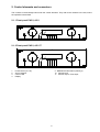
1
operating instructions
integrated amplifiers EVOLUTION A3.2, A5.2 / T
preamplifiers EVOLUTION PA3.2, PA5.2
Dear customer,
thank you for purchasing this AVM product. you own now a versatile, excellent sounding hifi
component. Before enjoying music, please read this manual carefully. After that you will know how
to use your new AVM component in the optimal way.
Sincerely yours
Your AVM-Team
Declaration of conformity (for EC only)
We herewith confirm, that the unit to which this manual belongs fulfills the EC rules necessary to
obtain the sign
the necessary measurements were taken with positive results.
AVM Audio Video Manufaktur GmbH, Daimlerstraße 8, D-76316 Malsch
Website: www.avm-audio.com, E-mail: [email protected]
2
Table of contents
page
page
Präamble
Table of contents
2
3
1. Basic informations
1.1 Mechanical construction & supply
1.2 Preamplifier
1.3 Power amplifier
1.4 Tube preamplifier stage PA5.2, A5.2T
1.5 Tuner
1.6 Phono
1.7 D/A converter (option)
4
4
4
4
4
5
5
5
2. Control elements and connectors
6
2.1.1 Frontpanel PA3.2, A3.2
6
2.1.2 Frontpanel PA5.2, A5.2 / T
6
2.2.1 Rear panel PA3.2, A3.2
7
2.2.2 Rear panel A5.2
7
2.3 Pin configuration of connectors
7
2.4 Insertion and removal of plug-in cards
8
2.5 Setting of the phono card
9
2.6 Installation and cooling
10
2.7 Connection to mains
10
2.8 Connecting the analogue signal sources
10
2.9 Connection of digital sources
10
2.10 Connecting a recorder
10
2.11 Connecting processors and equalizers
10
2.12 Connecting subwoofers
11
2.12.1 Active subwoofers
11
2.12.2 Active subwoofers with built in filters 11
2.13 Connecting loudspeakers
11
2.13.1 A3.2
11
2.13.1 A5.2
11
2.13.3 Bi amping
11
2.14 Connecting power amplifiers
11
2.15 Trigger outputs
11
2.16 Remote control of power amplifiers
via audio cable
11
2.17 Headphones / front input
12
2.17.1 Headphones
12
2.17.2 Front input
12
2.18 Antenna connection
12
3. Basic operation
3.1 First connection to mains
3.2 Switching on / standby
3.3 Selecting the signal source
3.4 Volume setting
3.4.1 Setting of input sensitivity
3.5 Tuner
3.5.1 Tuning
3.5.2 Station memory
3.5.3 Selecting a station out of memory
13
13
13
13
13
13
14
14
14
14
3
4. Advanced settings, the menu system
4.1 RDS-Display
4.2 Scanmode
4.3 2 ch-mode
4.4 Bandwidth
4.5 Sensitivity
4.6 Tone control
4.7 Bass
4.8 Treble
4.9 Loudness
4.10 Balance
4.11 Input attenuation
4.12 Set poweramp
4.13 Set front connector
4.14 Set processor
15
15
15
15
15
15
15
15
15
16
16
16
16
16
16
5. Remote control
17
6. Cleaning
17
7. If something doesn’t work
17
8. Conditions of warranty (EC only)
18
9. Technical data
9.1 EVOLUTION PA3.2
9.2 EVOLUTION A3.2
9.3 EVOLUTION A5.2
9.4 Phono
9.3 Tuner
9.3 D/A converter
19
19
19
19
20
20
20
10. Appendix
10.1 personal setup
10.1.1 Set display brightness
10.1.2 bass & treble control
10.1.3 skip unused inputs
10.1.4 define input names
10.1.5 gain fix / variable
10.1.6 FM auto store
10.2 Reset
21
21
21
21
21
21
21
22
22
1. Basic information
1.1 Mechanical construction & supply
The case is fully made of aluminium. The audio-connectors are all gold plated to minimize electrical losses
and provide long lasting perfect contacts.
The PA3.2's power supply consists of an oversized toroidal transformer with minimized magnetic stray field
and 10.000 µF of capacitance. In the A3.2 / A5.2 a switch mode power supply delivers clean, hum-free
electrical energy for the analogue sections of the preamplifier. All voltages are additionally buffered by large
capacitors directly in the circuitry where they are needed. The power amplifiers are fed by a separate switch
mode power supply (A3.2) respective two independent switch mode power supplies - one for each channel
(A5.2) Thus independently of the demanded output power the power amplifier has no influence on the
preamp.
1.2 Preamplifier
The input circuits act extremely fast and use special semiconductors for exact and nearly noise free sound
reproduction. SMD technique allows a very compact circuit layout and thus extremely short signal paths.
The volume control is done by highly precise integrated circuits. They allow setting in 0,5 dB steps and their
channel balance is better than 0,05 dB. All this provides an absolutely precise, musical sound reproduction
from lowest to highest listening levels.
If you whish to correct the frequency response at low listening levels or to have more or less treble or bass,
you can activate the sound processor and set the frequency response. For linear reproduction the whole
circuitry is removed out of the signal path by relays and has absolutely no influence.
The preamp section has one balanced XLR input and five RCA-Cinch inputs. Additionally there are three
slots for plug in cards: one phono card, one tuner card and a digital card with three digital inputs.
One fixed level output for recording and a processor in/out for connection of equalizers are provided. The
two preamplifier outputs (RCA-Cinch and XLR) are driven by powerful output stages and can easily handle
longer cables with high capacitance.
1.3 Power amplifier (A3.2 and A5.2 only)
A3.2 and A5.2 use for each channel a separate powerful and efficient digital class-D amplifier. These
amplifiers have an analog feedback loop from output to input. This ensures a nearly load-independent
frequency response and a very good damping factor.
Further highlights are very low output noise, low distortion and an extremely good efficiency. Even when
delivering peak power levels to the speakers they deliver over 90% of the supplied energy to the speakers
and thus produce nearly no heat.
1.4 Tube preamplifier stage (PA5.2, A5.2T only)
These amps equipped with a tube stage in the preamp section. We use one double triode for each channel.
The triodes are operated fully balanced. They operate with grounded gates and are fed via the Cathodes.
This circuit design ensures very quick reaction without sound degrading feed back. The tubes are heated
with about 2 Watts of power. This ensures a very long life and constant characteristic over the whole lifetime.
Thanks to the wide operating range and the balanced operation mode PA5.2 and A5.2T offer a very good
dynamic performance and even a further step ahead in musical quality.
The high voltage for the tubes is generated by a separate power supply which is fed by a precisely regulated
DC voltage. A 300 Hz sine generator followed by a power stage and a toroidal transformer generate the
regulated high voltage. This power supply operates fully independent of the unstable mains voltage and thus
the tubes can always operate at a stable bias point.
4
1.5 Tuner (option)
The tuner plug in card can be adapted to different reception situations. you can set bandwidth, and sensitivity
values in order to achieve optimal sound quality from aerial antenna as well as from cable. With it’s high
sensitivity the tuner can also work with a simple indoor antenna. The stereo decoder offers high channel
separation as well as very low noise.
The RDS section (audio data system, not available in all countries) is processor controlled and shows you
station names and texts with additional information about the program you are listening to.
The station memory allows you to store up to 63 stations. It stores not only their frequency, but also the
individual setting of sensitivity, bandwidth and mode (mono/stereo).
1.6 Phono (option)
The phono pcb is also installed in a slot in the rear panel of the unit. You can connect MC pickups as well as
MM-types. The phono pcb is very versatile and allows individual setting of cartridge type, cartridge load and
gain. The RIAA-equalization uses precise film capacitors and has a built in subsonic filter. So it works well
with most of all cartridges on the market.
1.7 D/A-converter (option)
The optional D/A-converter can also be plugged into a slot from the rear panel. It offers 3 digital inputs: The
optical and the coaxial input accept digital signals from CD-players, digital tuners and other sources. The
USB input can be connected to a suitable Computer. PCs working with WINDOWS XP or higher as well as
most Apple computers recognize the USB input automatically soon after connection. There is normally no
need to install special driver software.
The converter uses upsampling technique (192 kHz/24 bits). The jitter coming from the digital input signal is
nearly completely eliminated. Upsampling to 192 kHz also spreads the inevitable quantization noise to a
broader frequency range and therefore reduces (compared with CD format) the part of quantization noise in
the audible frequency range by a factor of over 4.
The D/A conversion is done by a highly precise IC which works with 24 bits accuracy. The reconstructed
music signal offers therefore crystal clear original sound with no loss of fine details.
5
2. Control elements and connectors
The numbers in the drawings below mark the control elements. They refer to the numbers in the text, where
the operation is described.
2.1.1 Front panel PA3.2, A3.2
1
2
3 4
5
6
7
8
9
10
11
5
6
7
8
9
10
11
2.1.2 Front panel PA5.2, A5.2 /T
1
1
2
3
4
2
3 4
Power button (on / off)
Source selector
Control LED
Display
5 - 9Multifunctional buttons (soft keys)
10 Volume knob
11 Phones output / Front input
6
2.2.1 Rear panel PA3.2, A3.2
30
I
O
12 13 14
15
16
17 18
19
20
21 22
23
24 25
26
27 28 29
2.2.2 Rear panel A5.2 / T
31
32
I
O
12 13 14
15
16
17 18
19
12 - 14 Digital inputs (Option)
15 Antenna socket (Option)
16 Phono input (Option)
17 Ground socket for turntable chassis
18 Input 1 (XLR)
19 Inputs 1 - 5 (RCA-Cinch)
20 Output for recorder (fixed level)
21 Processor output
22 Processor input
23 RS 232 connector
24 Pre amplifier output (RCA-Cinch)
20
21 22
25
26
27
28
29
30
Connector for external IR-sensor
Trigger outputs
Pre amplifier output (XLR)
Mains switch
Mains connector
Speakers output, A3.2
(red = Plus, black = GND)
Speakers output B, A5.2 / T
(red = Plus, black = GND)
Speakers output A, A5.2 / T
(red = Plus, black = GND)
31
32
23
24 25
26
27 28 29
2.3 Pin configuration of connectors
2
1
3
1
2
3,5mm stereo
infrared input
3
GND
XLR-input
1 = GND (shield)
2 = non inverting input
3 = inverting input
3,5mm mono
trigger outputs
XLR-output
IR-Signal +5V supply
external IR-input(socket 25)
1 = GND (shield)
2 = non inverting output
3 = inverting output
7
GND
+8V trigger
Trigger out (sockets 26)
2.4 Insertion and removal of plug-in cards
CAUTION: Before installing or removing cards ensure that the power plug is disconnected. Printed
circuit boards are never to be installed or removed with the unit switched on. If you are
inexperienced in working with electrical appliances it is recommended that you request your dealer
to install the plug–in cards.
We offer three plug in cards: A tuner card and a phono input and a digital input. For these cards the units
have 3 slots on the rear panel:
•
•
•
The (seen from the rear side) most right is for phono
The place in the middle is for tuner
The (seen from the rear side) most left is for digital I/O
The cover plates are each secured to the housing with a screw above and below. Before removing a cover
plate, unscrew both screws entirely. The cover plate can now be removed.
Rotate the card that is to be installed in such a way that the components are on the left side. Insert the new
card into the free slot. Ensure that the plug of the circuit board mates with the relevant socket inside the unit.
Push the card firmly home but do not use force. At the end of the procedure the rear face of the card must be
in level with the other rear surfaces. After the two securing screws have been firmly replaced the unit is
ready for operation.
NOTE: The plugs of the circuit boards are mounted different heights. This ensures that a phono card
doesn't fit into the slot where the tuner must be installed and vice versa. So please make sure to
install each card in the right slot and do not use force when pushing the card in.
8
2.5 Setting of the phono card (option)
To ensure that the phono card works in an optimal way, it must be set according to the requirements of the
cartridge. Please refer to the operating manual / technical data of your cartridge to find out the correct
settings. The setting is done by switches on the pcb. The upper switches are for the right channel, the lower
for the left channel. The switches for both channels must be set identically.
S1
MM-cartridges
Output voltage
Load capacitance
MC-cartridges
Output voltage
Load resistance
S2l
S3l S4l S5l
S2r
S3r S4r S5r
< 1 mV
1 mV – 2,5 mV
2,5 mV - 5 mV
> 5 mV
up to 200 pF
200 - 350 pF
350 - 450 pF
450 - 600 pF
S1/1+2 S2/1 S2/2 S3/1 S3/2 S4/1 S4/2 S5/1 S5/2
OFF
OFF OFF OFF OFF
ON ON
OFF ON
ON OFF
OFF OFF
OFF OFF
ON OFF
OFF ON
ON ON
S1/1+2 S2/1 S2/2 S3/1 S3/2 S4/1 S4/2 S5/1 S5/2
ON
ON ON
OFF OFF
< 100 µV
ON ON
100 µV - 250 µV
OFF ON
250 µV - 500 µV
ON OFF
> 500 µV
OFF OFF
25 - 75 Ohms
ON ON
75 - 150 Ohms
ON OFF
150 - 500 Ohms
OFF ON
> 500 Ohms
OFF OFF
9
2.6 Installation and cooling
The unit can become hot depending on demanded output power and environmental temperature. Therefore
it is important, that the cooling air can flow unhinderedly into the air inlet in the bottom and flow out through
the holes in the rear panel. Direct exposure to sunlight is not recommended, this can heat up the unit.
2.7 Connection to mains
Connect the unit to the mains outlet by using the power cord which is (in some countries) delivered together
with the unit. Make sure that mains voltage is according to the value printed on the rear panel (near mains
connector (29)). Let the unit be switched off until all audio connections are made.
2.8 Connecting the analogue signal sources
Connect the outputs of your signal sources to the inputs (18, 19). The upper row of the RCA cinch
connectors (19, white) is for left channel, the lower row (19, red) is for right channel. The right (seen from
rear side!) XLR input (18) is for left channel, the other one for right channel.
NOTE: XLR input IN1 (18) and RCA-Cinch input IN1 (19) are internally paralleled and should only be
connected to a signal source alternatively.
If your amplifier is equipped with a built in phono preamplifier (option), connect the output of the turntable
with inputs (16) and connect the chassis ground wire to the ground connector (17).
2.9 Connection of digital sources (option)
SPDIF inputs
Sat receivers, CD drives, MD recorders and other can be connected to the optical or coaxial inputs (13, 14).
USB connector
Use a suitable USB cable and connect the USB input (12) to your computer. PC working with WINDOWS XP
or higher as well as most Apple computers recognize the USB input automatically. Installation of a special
driver software is normally not necessary.
To play music stored on your computer you must set it's output to USB and the volume to maximum. These
settings and how to create playlists, how to play certain music titles depend on the software you use. Please
refer to the corresponding software manual.
2.10 Connecting a recorder
Connect the recorder’s output to one of the inputs (18). The inputs of the recorder must be connected to the
fixed level outputs (20).
2.11 Connecting processors / equalizers
Connect the processor’s / equalizer's outputs to the inputs proc in (22). The inputs of the processor must be
connected to the outputs proc out (21). Additionally you must activate the processor loop (see 4.14)
10
2.12 Connecting subwoofers
2.12.1 Active subwoofers without filters
If you use an active subwoofer (with built in power amplifier), simply connect it's input to the proc out (21)
and adjust the bass level at the subwoofer. If the subwoofer has a trigger input, connect it to the trigger
output (26).
2.12.2 Active subwoofers with built in filters
Most active subwoofers have a built in frequency divider network. They receive the full range signal from the
amplifier and feed the filtered signal (full range minus bass) back. This kind of subwoofer can be connected
to the processor in / output: Connect the subwoofer's inputs to the processor outputs (21) and the
subwoofer's outputs to the processor inputs (22). Now activate the processor function (see chapter 4.14).
If the subwoofer has a trigger input, connect it to the trigger output (26).
2.13 Connecting the loudspeakers (A3.2 and A5.2)
2.13.1 A3.2
Connect the speakers to the speaker terminals (30). Use only good speaker cables with sufficient diameter.
Make sure, that the red terminals are connected to the red or “ + “ terminals of the speakers and the black
terminals to the black or “ – “ terminals of the speakers.
2.13.2 A5.2
The A5.2 has two switcheable speaker outlets. Connect one pair of the speakers to the speaker terminals
(31), the other one to the terminals (132). Use only good speaker cables with sufficient diameter. Make sure,
that the red terminals are connected to the red or “ + “ terminals of the speakers and the black terminals to
the black or “ – “ terminals of the speakers.
The outputs can be activated or deactivated via the menu (see 4.12)
2.13.3 Bi amping
Many loudspeakers have bi-amping terminals. That means that the bass and the mid / hi range chassis can
be connected independently to two amplifiers (bi amping). For the A3.2 and A5.2 we recommend the use of
a pair of our mono amplifiers M3.2 for the bass and the A3.2's / A5.2's built in power amplifiers for mid an
treble range. The M3.2 match ideally with A3.2 and A5.2. They offer the same warm music reproduction.
2.14 Connecting power amplifiers (PA3.2)
Connect the power amplifiers to the preamplifier outputs. You can use RCA Cinch (24) as well as balaced
XLR outputs (27). Both outputs are decoupled from each other and can also be used in parallel for biamping.
2.15 Trigger outputs
Connect the trigger outputs (26) to the trigger inputs of the power amplifier or (if connected) the subwoofer.
Then these units will automatically switch on and off together with the PA3.2, A3.2 or A5.2. The pinning of
the trigger outputs is described in chapter 2.3
2.16 Remote control of power amplifiers via audio cable
If you use an AVM power amplifier of the newest Generation (MA3.2, MA8, SA8) then this unit will
automatically be switched on and off via the connected audio cable. There is no need for an additional
trigger cable (see manual of power amplifier).
11
2.17 Headphones / front input
2.17.1 Headphones
Plug the 3.3 mm headphones plug to the headphone jack (11). The loudspeaker and preamp outputs will
mute automatically when the plug is in.
2.17.2 Front input
The 3.5 mm jack in the front panel (11) can be configured as an additional input (see 4.13). You can use it
then for easy connection of a music player.
NOTE: the front input is connected in parallel to the rear input IN5. The inputs are naturally decoupled from
each other. If you use the front input you must switch off a signal source which is eventually connected to the
rear input IN5. There is off course no risc of damage for the units. But the signals of BOTH sources will
otherwise be mixed and be audible at the same time.
2.18 Antenna connection (if optional tuner is installed)
Connect the Antenna cable to the antenna socket (15).
12
3. Basic operation
3.1 First connection to mains
When the amplifier is connected to mains and switched on for the first time the it checks it’s configuration
and if all installed components work properly. The procedure is shown in the display. After that the unit will
switch to stand by.
3.2 Switching on / standby
Using the button power (1) you can switch between on (operate) and stand by. In the on state the display (4)
lights up and the LED (3) is off. In stand by mode the display (4) is off and the LED (3) is on to indicate that
the unit is still connected to mains.
CAUTION: When switched to stand by the unit is still connected to mains. In case of thunderstorm or if you
leave the house for a longer time we recommend that you switch the amplifier off by using the mains switch
(28) or pull the mains plug.
3.3 Selecting the signal source
Use the program selector (2) to select a signal source. The selected source is indicated in the display (4).
3.4 Volume setting
Use the rotary encoder (10) to set the desired volume. Depending on rotating speed the volume increases /
decreases in 0,5 dB steps (slow) or 3 dB steps (fast). The actual setting is shown in the display (4).
3.4.1 Setting of input sensitivity
The level of signal sources differs often by several dBs. So you recognize a step in volume, when switching
between two inputs. With the sensitivity setting menu you can avoid this. The sensitivity of each input can be
adjusted between – 9.5 dB and + 10.0 dB.
Select any input (but NOT the Tuner or CD) and chose a convenient volume level. Now press the button
MENU (7, under the display) for more than 2 seconds. The button is now marked "EXIT LVL". Pressing this
button again will exit the level setting mode and bring the unit back to normal operating mode.
While level setting is active the display shows the actual level instead of the volume. Level can be set using
the volume knob (10). Now you can switch between the sources and adjust the levels.
When this is done press the "EXIT LVL" knob (7) and bring the unit back to normal operating mode. All level
settings are now stored.
NOTE: While the level setting mode is active the unit will not respond to any remote control command.
13
3.5 Tuner (option)
The tuner can be selected using the program selector (2). The basic functions of the tuner can then be
accessed by the buttons right under the display (5 - 9). For more sophisticated functions see chapter 4.
3.5.1 Tuning
Depending on the selected mode (manual / auto, see 4.2) the most right buttons (8, 9) under the display (4)
are named AUT or MAN. In AUT-mode a tip on one of the buttons lets the tuner automatically seek
the next upper or lower station. In MAN mode the frequency changes in 50 kHz-steps as long as the button
is pressed. In this case the tuning indicator shown in the display (4) helps you to tune correctly to the desired
station. If tuning is correct it will show "locked“.
NOTE: To optimize the sound quality you can use the functions mode, sensitivity and bandwidth, which
are described later on in chapter 4.3 to 4.5
3.5.2 Station memory
Storing a new station
If you want to store a certain station in the memory, press the button MENU (7) under the display (4) for
more than 2 seconds. The display will propose the next free memory position for storage (for example: if 5
stations are already stored position 6 will be proposed). Using the "MOVE" buttons (5, 6) you can change the
position.
Modifying, moving or deleting an existing station
If the tuner is set to an already stored station you can change it's settings, move it to a different position or
delete it. First change settings (mono/stereo, bandwidth or other). Then press the button MENU (7) under the
display (4) for more than 2 seconds. If you then press "STORE" the station will be stored anew at the old
position with the changed settings. Using the buttons "MOVE" allows you to change the position of this
station before storing. "DELETE" will erase the station out of the memory. "EXIT" will bring the unit back to
normal operating mode without changing the memory.
NOTE: The station memory allows you to store up to 63 stations. It stores not only their frequency, but also
the individual setting (mono/stereo, bandwidth or other).
3.5.3 Selecting a station out of the memory
The buttons STAT (5, 6) select the stations stored in the memory. A short tip switches to the next /
previous station. Holding the button down scans automatically up / down. The number of the actual station is
shown in the display ("STAT xx").
14
4. Menu system
The PA3.2 / A3.2 / A5.2 offer a lot of custom specific settings in their menu system. To enter the menu just
tip on the button MENU (7). The button now changes to EXIT. A second tip on this button leads you to the
normal operating mode. When the menu system is active you can select the desired function using the
buttons ITEM (5, 6). The setting is done using the buttons VALUE (8, 9). Depending on the actual
source the menu system offers the following settings:
4.1 RDS-Display (tuner must be selected as source)
Choose if station NAME, RDS-TEXT or FREQUENCY is displayed.
4.2 Scanmode (tuner must be selected as source)
Set tuning mode between "auto" or "manual". (See also 3.5.1)
4.3 2-ch-Mode (tuner must be selected as source)
Set tuner to mono or stereo to obtain best sound.
NOTE: Depending on actual setting the threshold for auto tuning will change (sensitive in MONO, less
sensitive in STEREO).
4.4 Bandwidth (tuner must be selected as source)
Select bandwidth "narrow" / "wide" for best reception.
4.5 Sensitivity (tuner must be selected as source)
Choose between "local" (in case the tuner operates from a cable) and "distant" (if operated from antenna)
4.6 Tone control
Set tone control to "bypass" (= linear) or "active". In case the tone control is activated "TONE ON" is shown
in the display (4), otherwise "LINEAR".
You can choose if you want to change bass and treble settings simultaneously for all inputs ("global") or
especially for the actual input ("individual"). See 10.1.2
The loudness function depends on speakers and properties of the listening room and is therefore always
"global".
NOTE: In case tone control is set to "bypass" the menu will skip the bass, treble, and loudness settings (4.7 4.9).
Set tone control to "bypass" (= linear) or "active". In case the tone control is activated a "TONE ON" is shown
in the display (4).
4.7 Bass
Set bass level between – 5 and + 9.
4.8 Treble
Set treble level between – 7 and + 7.
15
4.9 Loudness
If you listen to music at low levels, you often recognize that bass and treble reproduction are weak. This is
because the human ear is not sensitive to bass and treble at low sound levels. To compensate this you can
use the parametric loudness function of the C6m. This function will increase bass and treble levels when you
decrease the volume. When the volume is increased the frequency response will be more and more flat and
remain linear at high volume levels. In order to obtain best results you have to proceed in the following way:
Set the amplifier to a moderate volume level. Using the buttons VALUE (8, 9) choose in the loudness
menu a curve ( "of" and 1 to 9) which gives best sound impression and exit the menu (button EXIT (7)).
NOTE: The loudness function selects automatically the correct curve depending on actual volume setting.
So if you change volume a different curve than previously selected may be shown in the loudness menu.
This is not a malfunction.
4.10 Balance
Set the balance between right and left channel for optimal stereo image.
4.11 Input attenuation
If a signal source produces a too high level and overdrives the inputs of the amplifier you will her some
distortions and pop-noise even if volume is set to minimum. In this case set the input attenuation to ACTIVE.
An attenuation circuit placed directly behind the input will be activated and reduce the incoming signal level
by 6 dB thus preventing the input stage from overdrive.
NOTE: This function is only available on inputs 1-3 and if one of thes inputs is actually selected.
4.12 Set poweramp
A3.2
You can set the power amplifier ON or OFF. This is useful if you have connected a headphone amp or a
separate power amplifier to the pre out (24, 27).
A5.2
Activate / deactivate the two speaker outputs (31, 32).
4.13 Set front connector
You can select the function of the 3.5 mm jack on the front panel (11): Phones output or front input (see also
2.17)
4.14 Set processor (see also 2.8, 2.9)
Switches processor function "on" / "off". If the processor is activated, it influences the signals on the speaker
outputs. The signals on fix out (23) are not affected.
16
5. Remote control
The main functions of the can be controlled by the RC3: ON/OFF, Volume control, source and station select.
The RC3 works up to distances of 7 meters. For best function point with the RC3 to the front panel of your hifi set. If the hi-fi set doesn’t react or reacts only over short distances, the batteries of the RC3 must be
changed.
Changing batteries
RC3 Bottom view
Unscrew the 6 marked screws (CAUTION, do NOT unscrew the 2 unmarked screws in the middle). Take the
bottom plate with the mounted pcb out. Remove the worn batteries and replace them with two new batteries
(type CR2032, 3V Lithium cells). Make sure that polarity is correct (the "+" sign must be on top). Insert the
bottom plate and screw it tight.
6. Cleaning
Use a soft cloth and normal glass cleansing fluid.
CAUTION: Make sure that no fluid comes into the unit. Do not use scouring cleaners.
7. If something doesn’t work.......
Some putative defects are often caused by mistakes in operation. Sometimes other units connected to the
amplifier can cause problems. Therefore please read the following tips before you consult your dealer or us.
1. Amplifier is muted
a)
b)
c)
d)
e)
Mute function active, press button MUTE on remote control or increase volume using rotary encoder (10)
Poweramp is switched off. Activate power amplifier (see 4.12).
PROCESSOR function is activated. Switch processor off (see 4.14).
Phones are plugged. Pull phones plug out.
Inadvertent switching to standby by remote control. Press power button (1). If LED indicator and display
do not light up a fuse can be blown due to overvoltage (thunderstorm). Please contact your dealer.
2. Amplifier switches off during normal operation
This can happen if the temperature inside the unit becomes too high. In this case the amplifier switches off
and the display shows “overheat”. Switch the unit off and let it cool down for five minutes.
3. Hum
a) Hum while playing records: Make sure that the chassis of your record player is properly grounded.
b) Continuous hum is in most cases caused by an unwanted ground loop. Insert a ground breaking filter nto
all antenna cables connected to the amplifier or to units which are connected to the amp.
4. Infrared remote control doesn’t work
a) Check the batteries of your remote control transmitter
b) Point with the remote control transmitter directly to the unit.
17
8. Conditions of warranty (EC only)
If despite expectations a defect occurs that cannot be repaired by yourself or your dealer, we undertake the
repair of your unit free of charge for up to five years from date of purchase. The warranty covers the costs of
material and working time, transport costs are to be borne by the owner.
Provisions for this warranty are:
•
The unit must have been purchased from an authorized dealer. Equipment from other sources will not be
repaired, not even at charge.
•
The warranty registration card, together with a copy of the bill of sale, must be received by us within four
weeks of the date of purchase.
•
The defect must not have been caused by improper handling or misuse.
•
Return the unit to us only in its original packing. If this is not possible we are entitled to refuse
acceptance. We will not assume responsibility for transport damage under any circumstances.
•
A short description of the defect is to be included with the returned unit.
•
In cases of doubt we reserve the right to request a copy of the bill of sale.
•
We also reserve the right to levy a handling charge for items returned without good or valid reason, or if
the unit proves to be not defective.
NOTE: If you are returning the unit from a country other than Germany you should ensure that correct export
documents are obtained. We cannot accept any charges for costs arising from improper or incomplete export
documentation.
If you have purchased your unit from a dealer outside Germany please refer to him or the relevant importing
firm to process the warranty.
18
9. Technical data
9.1 EVOLUTION PA3.2
Sensitivity all inputs (output = 1V)
20 mV – 450 mV (adjustable)
Sensitivity input 1 XLR&Cinch(output = 2V) 40 mV – 900 mV (adjustable) US-version only
Sensitivity other inputs (output = 2V)
20 mV – 450 mV (adjustable) US-version only
Input impedance balanced XLR
14 kOhms
Input impedance RCA Cinch
6,8 kOhms
Output impedance pre out RCA-cinch
100 Ohms
Output impedance pre out XLR
150 Ohms
S/N
105 dB (A)
Frequency response
0 Hz - > 100 kHz
THD (25 W/4 Ohm)
< 0,001%
Power consumption
Power supply
(Upon request
Dimensions (W x H x D)
Weight
0,1 W (stand by) / max 15 W
AC 230V / 50-60Hz
AC 115 V / 50-60 Hz)
430 mm x 90 mm x 310 mm
5,5 kg
9.2 EVOLUTION A3.2
Sensitivity (25 W/4 Ohm)
Input impedance balanced XLR
Input impedance RCA Cinch
Output impedance pre out RCA-cinch
Output impedance pre out XLR
S/N pre out
S/N speakers out
Frequency response pre out
Frequency response speakers out
THD (25 W/4 Ohm)
Damping factor
Output power
20 mV – 180 mV (adjustable)
14 kOhms
6,8 kOhms
100 Ohms
150 Ohms
103 dB (A)
>95 dB (A)
0 Hz - > 100 kHz
<5 Hz - > 40 kHz
< 0,1%
>100
2x100 W (8 Ohms) / 2x175 W (4 Ohms)
Power consumption
Power supply
(Upon request
Dimensions (W x H x D)
Weight
0,5 W (stand by) / max 450 W
AC 230V / 50-60Hz
AC 115 V / 50-60 Hz)
430 mm x 90 mm x 310 mm
6 kg
9.3 EVOLUTION A5.2
Sensitivity (25 W/4 Ohm)
Input impedance balanced XLR
Input impedance RCA Cinch
Output impedance pre out RCA-cinch
Output impedance pre out XLR
S/N pre out
S/N speakers out
Frequency response pre out
Frequency response speakers out
THD (25 W/4 Ohm)
Damping factor
Output power
20 mV – 180 mV (adjustable)
14 kOhms
6,8 kOhms
100 Ohms
150 Ohms
103 dB (A)
>95 dB (A)
0 Hz - > 100 kHz
<5 Hz - > 40 kHz
< 0,1%
>100
2x185 W (8 Ohms) / 2x350 W (4 Ohms)
Power consumption
Power supply
(Upon request
Dimensions (W x H x D)
Weight
0,5 W (stand by) / max 900 W
AC 230V / 50-60Hz
AC 115 V / 50-60 Hz)
430 mm x 130 mm x 370 mm
7.5 kg
19
9.4 Phono (option)
Sensitivity
Input impedance MM
S/N MM
Input impedance MC
S/N MC
Frequency response
Phono equalization
50µV - 10 mV (adjustable)
47 kOhms // 100 - 450 pF (adjustable)
83 dB (A)
75 Ohms - 1 kOhm (adjustable)
79 dB (A)
<5 Hz - > 50 kHz
according to RIAA +/- 0,3 dB
9.5 Tuner (option)
Frequency range
Step
Antenna impedance
Sensitivity mono / stereo
S/N mono / stereo
THD mono / stereo
Frequency response
Channel separation
87,5 MHz – 108,0 MHz
50 kHz
75 Ohms
1,5 µV / 50 µV
73 dB(A) / 68 dB(A)
0,1% / 0,5%
30 Hz – 16 kHz
55 dB
9.6 D/A converter (option)
Sampling frequecy
Frequency response
Deemphasis
THD&N
S/N
upsampling to 192 kHz / 24 bits
<20 Hz – >90 kHz (depends on input sample rate)
yes, automatically
<0,001%
>110 dB(A)
Input format dig in opt
Input format dig in coax
USB input
Input impedance dig in coax
Input level dig in coax
SPDIF, linear PCM 33 kHz – 96 kHz / 16 – 24 bits
SPDIF, linear PCM 33 kHz – 192 kHz / 16 – 24 bits
up to 48 kHz / 16 bits
75 Ohms
according to IEC 908
Issued: 11/2011. Changes reserved without notice
20
10 Appendix
10.1 Personal setup
Several settings can be done in the personal setup
To access the personal setup switch the unit to standby (power button (1)). Then press and hold the most
right key under the display (9). While holding that key switch the unit on (power button (1)). The display now
will show "**personal setup***". Release the button (9) and the unit is in personal setup mode.
When the personal setup is active you can select the desired function using the buttons ITEM (5, 6). The
button SELECT (8) activates the function. The setting is done using the buttons VALUE (8, 9). BACK
(7) leads you back to other settings. EXIT (7) exits the personal setup and stores the settings.
10.1.1 Set display brightness
Sets display brightness between 25% and 100%.
NOTE: The setting 100% can lead to "burn in" effects on the display if the unit is operated in this setting for a
very long time. So please switch the unit to stand by, if not in use.
10.1.2 bass & treble control
Choose if you want to change bass and treble settings simultaneously for all inputs ("global") or especially for
the actual input ("individual").
10.1.3 skip unused inputs
Deactivate unused inputs ("SKIP"). The unit will then skip these inputs when the source selector (2) is
rotated or if you select the inputs via the remote control.
10.1.4 define input names
You can individually set the names (max. 8 characters) of the different sources shown in the display (4).
Proceed as follows:
Press SELECT. The display shows now on the left side the old name, on the right side the new name. The
character to change is marked by an underscore. The keys ITEM (5, 6) select the input, the keys
POS (8, 9) select the position of the character to change. The marked character can be set using the
volume knob (10). When you are ready, simply press BACK (7). and the new names will be stored.
10.1.5 gain fix / variable
In a surround system the channel balance, tone setting and bass management are done by the decoder.
This setting must not be altered by another component because the channel balance the would be incorrect.
For this application the amplifier offers the fixed gain function (only for inputs 1-3).
Set the input where the main channels of the surround system are connected to fixed gain. When this input
is selected, tone controls are bypassed, balance is set to neutral position and the gain is on a fixed level
independently f the volume setting on the other inputs.
21
10.1.6 FM auto store (only if tuner installed)
This function is useful when storing a large quantity of stations from cable. Please note that the stations are
stored including the actual tuner setting (see 4.1 - 4.5). For cable we recommend: RDS-display = name,
scanmode = auto, 2-ch mode = stereo, bandwidth = narrow, sensitivity = local.
Once the tuner parameters are set in the desired way enter the personal setup and select "FM auto store".
Then press the button START (5). While the auto store function is in progress all stations are played audibly
for half a second. When the function is terminated the display shows for 2 seconds the number if stations
found. Then the unit comes back to normal tuner operating mode.
If desired you can now shift certain stations to different positions, change the settings and store back or
delete unwanted stations (see 3.5.2).
10.2 Reset
This function cancels certain or all settings and makes the unit return to default settings.
To perform the reset switch the unit to standby (power button (1)). Then press and hold the middle key (7)
under the display (4). While holding that key switch the unit on (power button (1)). The display now will show
the reset menu.
Select if you want to clear the station memory ("STAT"), the input names ("NAME") or reset the unit
completely ("ALL").
"CANCEL" will bring the unit back to normal operating mode without resetting any item.
22