1
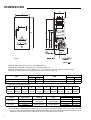
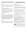
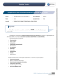
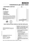
Instantaneous gas water heater
Models
W 125...T1
• installation
• operation
• maintenance
The Bosch instantaneous water heater is a high efficiency,
space saving answer to your water heating needs. All
Bosch instantaneous water heaters heat water only as
required; no energy is lost maintaining a large volume of
water at elevated temperatures as in tank-type storage
water heaters.
Suitable for heating potable water only – not approved
for space heating purposes.
READ INSTRUCTIONS CAREFULLY BEFORE INSTALLING
6 720 606 447 CA (05.05) AL
NOTICE TO INSTALLER: Please leave this
manual with the owner or affix adjacent to
appliance.
ASTRAVAN DISTRIBUTORS, LTD.
123 Charles Street
North Vancouver, B.C. V7H 1S1
Phone Canada: (604) 929-5488
Phone USA:
(206) 860-8448
Web Site: www.astravan.com
WARNING: If the information in this
manual is not followed exactly, a fire or
explosion may result causing property
damage, personal injury or death.
- Do not store or use gasoline or other flammable vapors and liquids in the vicinity of this or
any other applicance.
- WHAT TO DO IF YOU SMELL GAS
• Do not try to light any appliance.
• Do not touch any electrical switch; do not
use any phone in your building.
• Immediately call your gas supplier from a
neighbor’s phone. Follow the gas supplier’s
instructions.
• If you cannot reach your gas supplier, call
the fire department.
- Installation and service must be performed by
a qualified installer, service agency or the gas
supplier.
Note: In case of problems please contact your salesman or installer
DIMENSIONS
Figure 1
Maximum hydrostatic water pressure - 0.97 MPa (150 p.s.i.)
Maximum recommended working pressure - 0.69 MPa (100 p.s.i.)
Minimum working pressure - 0.01 1 MPa (2 p.s.i.) at 1.6 Litres/min. (0.5 U.S. Gal/min.) free discharge
Minimum recommended inlet water pressure for use with showers 40 p.s.i.g.
NG
Tap pressure inch
Manifold burner pressure inch
Altitude
Standard
High
5,7
4,6
3,35
2,7
Altitude
Standard
High
10,5
8,4
10,2
8,1
LPG
Tap pressure inch
Manifold burner pressure inch
Dimensions in millimetres (inches)
A
B
C
D
E
F
G
H
I
J
270
610
230
190
70
562
350
312
102
138
(10 5/8)
(25 3/8)
(9 1/8)
(7 1/2)
(2 3/4)
(22 1/8)
(13 3/4)
(12 1/4)
(4)
(5 3/8)
Model
W 125 K…
W 125 K…
Type of Gas
Altitude
Input
natural
propane
natural
propane
standart
(0-2,000 ft.)
high *
(2,000-4,500 ft.)
11.7 kW
(40,000 Btu/hr)
10.5 kW
(36,000 Btu/hr)
Main Burner Orifices
Size, mm
Qt.
1.25 diam.
6
0.76 diam.
6
1.25 diam.
6
0.76 diam.
6
* The high altitude ratings listed are Canadian Gas Association high altitude ratings and are only valid in Canada.
In the U.S., the National Fuel Gas Code, ANSI Z223.1/NFPA 54 recommends for high altitude installations above
2,000 feet, that the input rate be reduced 4% for each 1,000 feet above sea level.
2
FORWARD
This design complies with CAN 1-4.3-77 and ANS1
Z21.10.3b 1994 as an instantaneous gas water heater. In
addition the unit complies with CAN1-2.17-M80 for use at
high altitude, 2.000-4.5000 feet above sea level.
The BOSCH instantaneous gas water heater is designed to
operate on natural or propane gas; however, make sure that
gas on which heater is to operate is the same as specified
on the heater’s model/rating plate.
Instalation, operation and maitenance information is provided
in this manual. Installation and operation instructions should
be thoroughly reviewed before proceeding with installation
of the BOSCH instantaneous gas water heater.
In addition to these instrutions,the water heater shall be
installed in accordance with CAN1-B149 Installation Code
(in Canada) or ANSI Z223-1/NFFA 54 National Fuel Gas
Code (in U.S.) and/ or local installation cades. These shall
be carefully followed in all cases.
INSTALLATION INSTRUCTIONS
Note: Proper plumbing, venting, gas connections and an
adequate supply of combustion air are required for
safe and reliable operation. Ability equivalent to that
of a licensed tradesman in the field involved is required
for installation and/or servicing of these water heaters.
LOCATION
Before installing the BOSCH instantaneous gas water
heater consideration must be given to proper location. The
BOSCH W125K... instantaneous gas water heater may be
installed to supply hot water to remote locations. Location
should be as close to a chimney or gas vent as practical, in
an area with an adequate air supply and as centralized with
the piping system as possible. The heater should not be
located in an area where it will be subject to freezing. The
heater should be located in an area where leakage of the
heater or its connections will not result in damage to the
area adjacent to the heater or to lower floors of the structure.
Note: When such locations can not be avoided, it is
recommended that a suitable drain pan, adequately
drained, be installed under the heater. The pan must
not restrict combustion air flow.
AIR REQUIREMENTS
For safe operation, sufficient air for combustion, ventilation
and dilution of flue gases must be available. An insufficient
supply of air will result in a yellow luminous burner flame,
causing carboning or sooting of the heat exchanger.
In unconfined spaces, in buildings of normal construction,
infiltration normally is adequate to provide air for combustion,
ventilation and dilution of flue gases. However, a confined
space must be provided with two permanent openings to
provide combustion and ventilation air to the appliance. Each
opening shall have a free area of on square inch per 1,000
Btu/hr of total input rating of all the appliances in the
enclosure, but not less than 100 square inches. One opening
shall be within 12 inches of the top and one within 12 inches
of the bottom of the enclosure.
For either a confined or unconfined space in a building of
tight construction, with inadequate infiltration, air must be
drawn from the outdoors or from spaces that freely
communicate with the outdoors. Two permanent openings
located as indicated above are to be provided as follows:
1. When communicating with outdoors directly, or by
means of vertical ducts, each opening shall have a free
area of not less than one square inch per 4,000 Btu/hr of
total input of all appliances in the space.
2. When communicating with outdoors by means of
horizontal
ducts, each opening shall have a free area
of not less than one square inch per 2,000 Btu/hr of total
input of all appliances in the space.
3
WARNING
1. Flammable materials, gasoline, pressurized containers,
or any other items or articles that are potentially fire
hazards must never be placed on or adjacent to the
heater. The appliance area must be kept free of all
combustible materials, gasoline and other flammable
vapors and liquids.
2. Do not obstruct the flow of combustion and ventilation
air to the appliance.
This heather is designed certified for installation on a
combustible wall, in an alcove with minimum clearances to
combustible construction of 51mm (2 inches) from sides,
305mm (12 inches) from top and bottom. A minimum of
305mm (12 inches) shall be allowed for maintenance of
serviceable parts. Clearance from vent is dependent upon
the clearance rating of the venting material used; that is
type B-1 vent is approved for 1 inch clearance, B-2 vent for
2 inch, etc.
MOUNTING
The W125K…is designed certified for mounting to a wall.
The heather must not be installed directly on a carpeted
wall.
The heather must be mounted to the wall using appropriate
anchoring materials, through the four holes provided.
Expansion and contraction of piping due to changing water
temperature in pipes imparts movement to heater which, if
mounted directly to a brittle, board such as plasterboard
can cause failure of mounting.
Heater must be mounted level to assure proper operation.
VENTING
The BOSCH model W125K… instantaneous gas water
heater has a built-in a draft diverter is designed for indoor
installation only. The draft diverter outlet must be connected
to a clear, unobstructed vent of the same size or larger, refer
to:
In Canada, CAN 1-B149 Installation Code for detailed
requirements
In U.S., ANZI Z223.I/NFPA 54 National Fuel Gas Code
for detailed requirements
The minimum length of a vertical vent up to the terminal
must be 2 ½ feet.
WATER CONNECTIONS
The W125K comes supplied with a ½’’ NPT cold water inlet
adapter and a flexible wire braid hot water outlet with a ½’’
NPT connection.
4
G772_179
CLEARANCES
Figure 2
RELIEF VALVE
The listed pressure relief valve supplied must be installed
near the hot water outlet at time of installation of the
heater. No valve is to be placed between the relief valve
and the heater. A drain line must be connected to the
relief valve to direct discharge to a safe location. Do not
install reducing coupling or any other restriction in the
discharge line. The discharge line must be installed so
as to allow complete
drainage of both the valve and the line.
GAS CONNECTIONS
Before connecting the gas supply to the heater check
heater’s model/rating plate to make sure that gas on which
heater is to operate is the same as specified on the model/
rating plate.
The W125K…instantaneous gas water heater is supplied
with a gas pipe, a gas pressure regulator and a manual gas
cock that must be installed on the heater before attaching
the gas supply line, see figure 3. Failure to install gas pipe,
the main manual gas valve and the pressure regulator, or
the failure to install them in the sequence show in figure 3
will be in violation of the A.G.A. and C.G.A. certification of
the unit and can cause damage to heat changer.
BOSCH water heaters are shipped from the factory with
the gas pressure regulators preset for the gas shown on the
rating plate to the correct pressure.
In Canada, for high altitude operation;
In U.S., for standard altitude operation unless specially
marked as a high altitude unit.
Check to make sure that the gas listed on the rating plate is
same as gas listed on the pressure regulator. See PRESSURE
REGULATION section of this manual for information
regarding gas pressure settings.
Note: Before attaching the gas supply line, be sure that all
gas pipe is clean on the inside. To trap any dirt or
foreign material in the gas supply line, a dirt leg must
be incorporated in the piping. The drip leg must be
readily accessible and not subject to freezing
conditions. Install in accordance with
recommendations of serving gas supplier.
PROPANE SUPPLY
Joint compounds (pipe dope) shall be applied sparingly and
only to the male threads of pipe joints. Do not apply
compound to the first two threads. The joint compound used
must be resistant to the action of liquified petroleum gases.
Before placing water heater in operation check for gas
leakage.
Soap and water solution, or other material acceptable for
this purpose, shall be used in locating gas leaks. Matches,
candles, lighters, or other ignition sources shall not be used
for this purpose.
Figure 4
Where used with propane (LP gas) a separate correct
propane regulator must be installed at propane tank to deliver
propane to BOSCH regulator at 11’’ W.C. pressure.
PRESSURE TAP
PRESSURE REGULATOR
MANUAL GAS VALVE
Figure 3
WARNING
The heater and its individual shutoff valve must be
disconnected from the gas supply piping system during any
pressure testing of that system at test pressures in excess
3,45 KPa (½ psig).
The water heater must be isolated from the gas supply piping
system by closing its individual manual shutoff valve during
any pressure testing of the gas supply piping system at test
pressures equal to or less than 3,45 KPa (½ psig).
The water heater, including the pressure regulator and
manual valve provided with it, must not be operated at gas
supply pressures in excess of 3,45 KPa (½ psig).If
overpressure has occurred such as through improper testing
of the gas lines or emergency malfunction of the supply
system, the gas valve and regulator must be checked for
safe operation. Make sure that the outside vent valves are
protected against blockage. These are part of the gas supply
system, not the water heater. Vent blockage may occur during
ice storms.
5
OPERATING INSTRUCTIONS
WARNING
LIGHTING INSTRUCTIONS
If the water heater has been damaged or exposed to flooding, fire, or sooting do not operate the heater until all corrective steps have been taken by a qualified serviceman.
1. STOP! Read the safety information, (first section) of the
Lighting Instruction Plate on the cover.
FILLING
Before proceeding with operation of the water heater make
sure that the system is filled with water.
Turn the water flow selector handle clockwise (
)
against stop.
Open all hot water faucets connected to the W125K…to
allow trapped air to escape from heater and piping.
Close all faucets, once water flows freely and all air
has escaped from system.
The water heater is now ready to be lit.
SERVICE HINT
The screen (strainer) in the water valve, located in inlet of
the water valve, may require occasional cleaning due the
foreign material in the water supply. This will restrict the
flow of water and may affect heater operation and prolong
filling time. To inspect the screen, close the cold water supply valve ahead of the heater, disconnected cold water line
from inlet of water valve and remove screen from inlet. Clean
if required, replace screen in inlet to water valve, reconnected and open cold water supply valve.
LIGHTING
Light the water heater in accordance with the instructions
on the Lighting and Operating Plate on the water heater.
For your convenience, the instructions are repeated below.
2. The main manual gas valve must be closed (turn valve
handle clockwise
, see fig. below ) and the gas
valve button
slide to the far left under the OFF
mark.
3. Wait five (5) minutes to clear out any gas. If you smell
gas, stop! Follow ‘’B’’ in the safety information above on
this label. If you don’t smell gas, go to next step.
4. The pilot burner is located behind the peephole located
in the front center of the jacket directly below this
instruction plate.
5. Slide the gas valve button to right to pilot position (
)
and open main manual gas valve (by turning valve handle
counterclockwise
).
6. Fully depress gas valve button (
pushing pilot igniter button (
)
) and light pilot by
7. Observe pilot flame through peephole. The gas valve
button should be held down at least 10 seconds with
pilot burning. When the gas valve button is released the
pilot should continue to born.
- If the gas valve button does not pop up when released
stop and immediately call your service technician or gas
supplier.
- If the pilot will not stay lit after several tries, slide the gas
valve button to the left. Under the OFF (
) mark, turn
the manual gas valve to the off position and call your
service technician or gas supplier.
8. Slide gas valve button to the right to the ON position
(
) the heater will now fire when water is drawn at
a rate greater than the threshold flow rate (see manual).
Note: If main burner should fait to ignite make sure pilot is
burning. If not repeat lighting procedure steps 1 through 8.
6
TO TURN OFF GAS TO APPLIANCE
1. Close main manual gas valve and slide the gas valve
button to the OFF position.
PRESSURE TAP
PRESSURE REGULATOR
MANUAL GAS VALVE
PEEPHOLE
WATER TEMPERATURE CONTROL
To adjust water temperature use water flow selector, at
heater. For hot water rotate control Knob to the right.
GAS VALVE BUTTON
Turn counterPILOT IGNITOR BUTTON clockwise:
more water
WATER FLOW
- Warm
SELECTOR
PRESSURE REGULATION
The pressure regulator supplied with the water heater is
adjusted to operate on the gas specified on the rating plate
and:
- in Canada, is factory preset to deliver gas at the high
altitude pressure setting listed on the rating plate and as
shown below.
- in the U.S., is factory preset to deliver gas at the standard
altitude setting listed on the rating plate and as shown
below.
The pressure setting of the gas pressure regulator should
be checked at installation to assure that the setting is correct
for the gas being used and the altitude at which the
appliance is installed. See rating plate on the unit, or the
chart below for proper settings.
In Canada for a heater being installed at standard altitude
(0- 2.000 ft. elevation) the manifold pressure should be reset
at installation to value shown on the rating plate, or chart
below for standard altitude.
The gas pressures specified below refer to flow pressure
taken at the pressure tap in the gas inlet pipe (just above
pressure regulator, figure 5) while the heater is operating at
full input.
Appliance Regulator Pressure Setting
Type of Gas
natural
propone
natural
propane
kPa
1.41
2.61
1.14
2.09
Pressure tap
Inches, W.C.
5.7
10.5
4.6
8.4
Altitude
standart
(0.2,000 ft.)
high
(2,000-4,500 ft.)
Note: The high altitude ratings listed are Canadian Gas
Association high altitude ratings for the appliances and are
only valid in Canada. In the U.S. the National Fuel Gas Code,
ANSI Z 223.1/NFPA 54, recommends for high altitude
installations, above 2000 feet that the input rate be reduced
4% for each 1.000 feet above sea level.
Turn
clockwise:
less water
- hot
The control knob regulates the water temperature by adjusting the flow rate of the water through the heater:
- Maximum flow rate through the heater is 5L/min, (1.3
U.S. gal/min.) with temperature rise of 25°C (45°F) at
full input.
- Minimum flow rate through the heater is 2.3 L/min. (0.6
U.S. gal/min) with temperature rise of 55°C (99°F) at
full input.
For normal hot water use the control knob of water flow
selector should be turned clock wise (
) to stop and
remain in that position. This will permit control of remote
temperature by mixing more or less cold water with the hot
water supplied by the heater.
Note: If flow rate is adjusted to a point where water flow
through the heater is less than 2.3 L/min. the main
burner will shut-off. This is a safety feature.
Warning: Hot water can produce 3rd degree burns,
in 6 seconds at 60°C (140°F)
In 30 seconds at 54°C (130°F)
HIGH TEMPERATURE LIMIT SWITCH
The BOSCH W125K…instantaneous gas water heater is
equipped with a high temperature unit switch with a set
point of 90°C (194°F). If the water temperature at the sensing
bulb should exceed 90°C (194°F) the switch will open,
interrupting the safety circuit and stopping gas flow to the
pilot and main burner.
Pilot outage as a result of high limit operation indicates that
the heater is not functioning properly. The heater should be
checked by a qualified serviceman and the reason for
malfunction corrected. To relight pilot follow instructions
provided on the unit.
7
PREVENTIVE MAINTENANCE
PILOT AND MAIN BURNER
Check pilot and main burners at least every 12 months for
the proper flame characteristics.
10 mm
The pilot flame should envelop approximately 10 mm (3/8
inch) of tip of thermocouple.
If the main burners fail to exhibit above characteristics they
must be cleaned, either by blowing them off with compressed
air or by washing them in soap and water and rinsing.
If it proves necessary to wash the main burner assembly the
following procedure should be used:
1. Turn off the gas supply to the water heater.
2. Disconnect pilot gas tube at the gas valve and unscrew
the gas manifold assembly union nut, where the gas
manifold inlet pipe connects to the gas valve and remove
the gas burner assembly.
3. Wash in soap and water and then rinse.
4. Reassemble - Check for gas leaks after reassembly and
correct as required.
5. Refer to Lighting Procedure to relight the heater.
VENTING
3mm
The vent piping and finned heat exchanger should be checked
at least once a year for dust and carbon deposits and
cleaned as necessary.
PRESSURE RELIEF VALVE
Figure 6
If the pilot flame is too small, then the pilot burner must be
cleaned. The position of the igniter electrode should also
be checked to assure that electrode is approximately 3 mm
(1/8’’) from pilot, see figure 6.
The main burner should exhibit the following characteristics:
·
·
·
·
Provide complete combustion of gas.
Cause rapid ignition and carryover of flame across burners.
Operate quickly during ignition, burning and extinction.
Burner flames should be blue and there should be no lifting
of flames from burner ports, figure 7.
Figure 7
8
At least once a year the pressure relief valve should be
checked to insure that if it is in operating condition.
Before testing the relief valve take necessary precautions
to prevent water damage. Lift the lever on the valve several
times until the valve seats properly and operates freely. Do
not check the relief valve when hot water is being draw and
the main burner is on. Water exiting the valve under these
conditions would be hot.
If the pressure relief valve on the appliance discharges this
is an indication of water pressure above the pressure rating
of the relief valve. If the pressure relief valve continually
discharges on a periodic basis contact the water supplier
or local plumbing inspector on how to correct the situation.
Do not plug the pressure relief valve.
PERIODIC REMOVAL OF LIME DEPOSITS
In hard water areas, depending on frequency of use, the
heater should be checked for accumulation of calcium
carbonate (lime) and delimed, if necessary. Thereafter a
regular schedule, based on initial inspection findings, should
be set up to delime the heater. Delivering instructions are
available from your Bosch dealer.
8 700 703 038
8 700 203 027
8 703 305 197
NOTE:
THE HOT WATER OUTLET HAS BEEN UPGRADED TO A FLEXIBLE
TUBE. NOTE POSITIOON OF ASSEMBLY - FLAT COPPER WASHER
INSIDE BUSHING - THEN ATTACHED TO MALE END OF FLEX TUBE.
*DO NOT OVER TIGHTEN*
9
10
INTERIOR COMPONENTS DIAGRAM
AND PARTS LIST
Nº Description
Front shell
Water flow selector handle
#N/A
4
Draught diverter
5
Heat exchanger
6
Temperature limit
7
Hose
8
Main burner
8
Main burner
9
Washer
10 Sparking plug
11 Pilot burner ( 75 )
11a Filter
12 Pilot injector ( 5 )
12 Pilot orifice (49)
13 Pilot gas pipe
14 Thermocouple
15 Gas valve
15 Gas valve
16 Magnetic unit
17 Termo connection
18 Water valve
19 Repair set for water valve cover
20 Diaphragm
21 Slow-ignition valve (C)
22 Volumetric water governor
23 Selector screw
#N/A
25 Water strainer
26 Venturi (H)
W125
8705401730
8702000218
1
2
NG
LPG
NG
LPG
NG
LPG
8705505361
8705406149
8707206040
8700703038
8708120011
8708120301
8700103008
8708107002
8708105538
8700507055
8708200005
8748200173
8700707334
8747202083
8707011466
8707011145
8707201012
8747202209
8707002497
8703406204
8700503050
8708503063
8707402018
8708500166
8700507001
8708205210
11
ASTRAVAN DISTRIBUTORS, LTD.
123 Charles Street
North Vancouver, B.C. V7H 1S1
Phone Canada: (604) 929-5488
Phone USA:
(206) 860-8448
Web Site: www.astravan.com